EP1226724B1 - Method and apparatus for providing forward link softer handoff in a code division multiple access communication system - Google Patents
Method and apparatus for providing forward link softer handoff in a code division multiple access communication system Download PDFInfo
- Publication number
- EP1226724B1 EP1226724B1 EP00976609A EP00976609A EP1226724B1 EP 1226724 B1 EP1226724 B1 EP 1226724B1 EP 00976609 A EP00976609 A EP 00976609A EP 00976609 A EP00976609 A EP 00976609A EP 1226724 B1 EP1226724 B1 EP 1226724B1
- Authority
- EP
- European Patent Office
- Prior art keywords
- antenna array
- softer handoff
- recited
- polarization
- antenna
- Prior art date
- Legal status (The legal status is an assumption and is not a legal conclusion. Google has not performed a legal analysis and makes no representation as to the accuracy of the status listed.)
- Expired - Lifetime
Links
- 238000000034 method Methods 0.000 title claims abstract description 18
- 230000005855 radiation Effects 0.000 claims abstract description 29
- 230000010287 polarization Effects 0.000 claims abstract description 22
- 238000003491 array Methods 0.000 claims abstract description 10
- 230000010267 cellular communication Effects 0.000 claims description 5
- 239000011159 matrix material Substances 0.000 claims description 5
- 239000000969 carrier Substances 0.000 claims description 2
- 230000009977 dual effect Effects 0.000 abstract description 6
- 230000015556 catabolic process Effects 0.000 description 4
- 238000006731 degradation reaction Methods 0.000 description 4
- 230000008901 benefit Effects 0.000 description 3
- 230000001413 cellular effect Effects 0.000 description 3
- 238000005388 cross polarization Methods 0.000 description 3
- 238000012986 modification Methods 0.000 description 3
- 230000004048 modification Effects 0.000 description 3
- 230000002596 correlated effect Effects 0.000 description 1
- 238000010586 diagram Methods 0.000 description 1
- 238000000926 separation method Methods 0.000 description 1
Images


Classifications
-
- H—ELECTRICITY
- H04—ELECTRIC COMMUNICATION TECHNIQUE
- H04W—WIRELESS COMMUNICATION NETWORKS
- H04W92/00—Interfaces specially adapted for wireless communication networks
- H04W92/16—Interfaces between hierarchically similar devices
- H04W92/20—Interfaces between hierarchically similar devices between access points
-
- H—ELECTRICITY
- H01—ELECTRIC ELEMENTS
- H01Q—ANTENNAS, i.e. RADIO AERIALS
- H01Q1/00—Details of, or arrangements associated with, antennas
- H01Q1/12—Supports; Mounting means
- H01Q1/22—Supports; Mounting means by structural association with other equipment or articles
- H01Q1/24—Supports; Mounting means by structural association with other equipment or articles with receiving set
- H01Q1/241—Supports; Mounting means by structural association with other equipment or articles with receiving set used in mobile communications, e.g. GSM
- H01Q1/246—Supports; Mounting means by structural association with other equipment or articles with receiving set used in mobile communications, e.g. GSM specially adapted for base stations
-
- H—ELECTRICITY
- H01—ELECTRIC ELEMENTS
- H01Q—ANTENNAS, i.e. RADIO AERIALS
- H01Q21/00—Antenna arrays or systems
- H01Q21/24—Combinations of antenna units polarised in different directions for transmitting or receiving circularly and elliptically polarised waves or waves linearly polarised in any direction
-
- H—ELECTRICITY
- H01—ELECTRIC ELEMENTS
- H01Q—ANTENNAS, i.e. RADIO AERIALS
- H01Q3/00—Arrangements for changing or varying the orientation or the shape of the directional pattern of the waves radiated from an antenna or antenna system
- H01Q3/22—Arrangements for changing or varying the orientation or the shape of the directional pattern of the waves radiated from an antenna or antenna system varying the orientation in accordance with variation of frequency of radiated wave
-
- H—ELECTRICITY
- H04—ELECTRIC COMMUNICATION TECHNIQUE
- H04W—WIRELESS COMMUNICATION NETWORKS
- H04W36/00—Hand-off or reselection arrangements
- H04W36/16—Performing reselection for specific purposes
- H04W36/18—Performing reselection for specific purposes for allowing seamless reselection, e.g. soft reselection
-
- H—ELECTRICITY
- H04—ELECTRIC COMMUNICATION TECHNIQUE
- H04W—WIRELESS COMMUNICATION NETWORKS
- H04W84/00—Network topologies
- H04W84/02—Hierarchically pre-organised networks, e.g. paging networks, cellular networks, WLAN [Wireless Local Area Network] or WLL [Wireless Local Loop]
- H04W84/04—Large scale networks; Deep hierarchical networks
- H04W84/042—Public Land Mobile systems, e.g. cellular systems
Definitions
- the present invention relates generally to communication systems, and more particularly, to a method and apparatus for providing forward link softer handoff in a code division multiple access (CDMA) communication system with antenna arrays, including narrow beam antennas.
- CDMA code division multiple access
- a cellular communication system typically includes one or more mobile stations or units, one or more base stations, and a mobile telephone switching office. Although only three cells 14 and two mobile stations 11 are shown in FIG. 1 , a typical cellular network may comprise hundreds of base stations, thousands of mobile stations, and more than one mobile telephone switching office. Each cell will have allocated to it one or more dedicated control channels and one or more voice channels. In rural areas, the antenna towers 12 are commonly located at the center of a cell 14 , thereby providing omni-directional coverage. In an omni-directional cell, the control channels and the active voice channels are broadcast in all areas of the cell, usually from a single antenna. Where base stations are more densely located, a sectorized antenna system may be employed as in the prior art, and shown by the schematic diagram of FIG.
- Sectorization requires directional antennas 20 having, for example, a 120 degree radiation pattern as illustrated in FIG. 2 .
- Each sector 22 is itself a cell having its own control channels and traffic channels.
- channel may refer to a specific carrier frequency in an analog system, to a specific carrier/slot combination in a hybrid TDMA/FDMA system such as IS-54 and GSM, or to a specific PN code in a CDMA system such as IS-95.
- Existing narrow beam antenna arrays which may comprise uniform linear arrays including dipoles or patch elements and passive beam forming networks including Butler matrices, typically produce several beams covering a sector. For example, a four beam pattern which includes four 30 degree beams covering a 120 degree sector or region is not uncommon. These beams typically have beam crossovers at approximately minus 4 dB, whereas sector antennas typically have beam crossovers at approximately minus 8 dB.
- beam-to-beam overlap within a narrow beam antenna pattern is significantly greater than sector-to-sector overlap within a sectorized antenna pattern, or even the overlap of beams at the edge of two narrow beam antennas.
- the forward link of adjacent beams produces interference in the beam overlap region.
- the beam overlap region of available narrow beam antenna panels is greater than the beam overlap region of available discrete antennas, because there is less control over the beams when using passive RF beam forming networks such as Butler Matrices.
- a typical beam-to-beam crossover in a narrow beam antenna pattern is approximately minus 4 dB, while sector antennas can be made narrower than the sectors they occupy, and crossover at approximately minus 8 dB. With more overlap, there is more degradation.
- narrow beam antennas are used for separate CDMA PN codes (i.e., one beam used for a current sector or PN), the additional overlap means more degradation on the forward link unless softer handoff is used.
- EP-A-0 895 436 discloses a beam forming apparatus and method for forming a plurality of directional beams within a sector as well as a full sector coverage beam. Uplink reception diversity is maintained through provision of either a single facet antenna or a pair of single facet antennas.
- the present invention provides an apparatus for providing polarization diversity in a code division multiple access cellular communication system, as claimed in claim 1.
- the present invention provides a method for providing polarization diversity in a code division multiple access cellular communication system, as claimed in claim 8.
- Narrow beam antenna 304 comprises Butler matrix 316 and a uniform linear array of antenna elements 320-326 .
- talk channel 302 is connected to switch 306 , which is connected to transmitters 308-314 , respectively.
- an antenna pattern is formed by routing a signal from one of the transmitters 308-314 to Butler matrix 316 , where it is thereafter distributed to antenna elements 320-326 .
- signals transmitted by transmitters 308 and 310 are phased and distributed by Butler matrix 316 and antenna elements 320-326 such that the patterns produced will be beams A and B, respectively.
- Each of the other beams (C and D) are formed in a similar fashion.
- the talk channel 302 is routed via switch 306 to transmitters 308 and 310 , which are coupled to the narrow beam antenna 304 , producing beam patterns A and B, thereby placing the mobile station within two adjacent beams of the narrow beam antenna 304 .
- beams A and B originate in a single narrow beam antenna panel, the beams have a higher correlation, thereby producing less path diversity benefit and resulting in a higher required transmit power allocation.
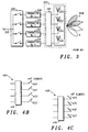
- FIGS. 4A-4C illustrate the utilization of dual polarized antenna arrays 404 and 406 including rerouting the softer handoff talk channel 402 from a radiation pattern 415 of the first antenna array 404 into a radiation pattern 417 of the second antenna array 406 .
- FIGS. 4B and 4C are included to give a clearer illustration of antenna arrays 404 and 406, respectively, and FIG. 4A illustrates, among other things, the antenna elements 420-427 that form dual polarized uniform linear array 418. As seen in FIGS.
- talk channel 402 is coupled to softer handoff router 430, which is coupled to first antenna array transmitters 440-446 and to second antenna array transmitters 448-454, respectively.
- Router 430 includes first switching device 432 and second switching device 434.
- the talk channel 402 is rerouted via router 430 to transmitter 440 of first antenna array and to transmitter 450 of second antenna array, which are coupled to antenna elements 420-423 with appropriate phasing from beam former 416, and to antenna elements 424-427 with appropriate phasing from beam former 419, respectively, thereby effectively rerouting the softer handoff talk channel 402 from radiation pattern B+ of the first antenna array 404 into radiation pattern B- of the second antenna array 406.
- the two diversity paths are less correlated, thereby improving the diversity gain.
- the first antenna array 404 is adapted to transmit a first plurality of radiation patterns 415 (A+, B+, C+, D+) defining a first coverage area.
- first antenna array 404 comprises a passive beam forming network 416 and antenna elements 420-423 of the dual polarization uniform linear array 418.
- antenna elements 420-423 comprise patch elements or dipoles.
- first antenna array 404 is described as corriprising a narrow beam antenna array including a passive beam forming network and a uniform linear array, it will be appreciated by those skilled in the art that other configurations may readily be utilized without departing from the scope of the present invention. For example; as illustrated in FIG.
- a plurality of discrete directive antennas such as sector antennas or dish antennas, may be used instead of the passive beam forming network/uniform linear array combination illustrated in FIGS. 4A-4C.
- the passive beam forming network 416 illustrated in FIGS. 4A-4C may be instead active electronic gain and phase weighting and summing to a linear or circular array as illustrated in FIG. 5B.
- a second antenna array 406 is adapted to transmit a second plurality of radiation patterns 417 (A-, B-, C-, D-) defining a second coverage area.
- second antenna array 406 comprises passive beam forming network 419 and antenna elements 424-427 of the dual polarization uniform linear array 418.
- the first and second coverage areas overlap.
- passive beam forming network 419 includes a Butler matrix
- uniform linear array 418 includes a plurality of antenna elements 424-427, which in the preferred embodiment comprise patch elements or dipoles.
- second antenna array 406 is described as comprising a narrow beam antenna array including a passive beam forming network and a uniform linear array, it will be appreciated by those skilled in the art that other configurations may readily be utilized without departing from the scope of the present invention.
- a plurality of discrete directive antennas such as sector antennas or dish antennas, may be used instead of the passive beam forming network/uniform linear array combination illustrated in FIGS. 4A-4C.
- the passive beam forming network 419 illustrated in FIGS. 4A-4C may be instead an active electronic gain and phase weighting and summing to a linear or circular array as illustrated in FIG. 5B.
- each of the first and second antenna arrays comprises a narrow beam antenna and each of the first and second plurality of radiation patterns include a first plurality of adjacent beams and a second plurality of adjacent beams, respectively.
- each of the first and second plurality of radiation patterns include a first plurality of adjacent beams and a second plurality of adjacent beams, respectively.
- other antenna array configurations, and other radiation patterns may be utilized without departing from the scope of the present invention.
- alternate frequencies may be placed on alternate polarizations, and a third carrier may be separated by two channel spacings, thereby allowing more efficient frequency combining.
- the present invention still provides two antenna arrays covering the same region, thereby allowing frequencies f1, f3, f5, etc. to be placed on one polarization (i.e. -45 degrees) and frequencies f2, f4, f6, etc. to be placed on another polarization (i.e. +45 degrees).
- the process begins at block 600 , wherein the step of transmitting, from a first antenna array, a first plurality of radiation patterns having a first plurality and defining a first coverage area is performed. Thereafter, as shown at block 602, the step of transmitting, from a second antenna array, a second plurality of radiation patterns having a second polarization different from the first polarization and defining a second coverage area, the first and second coverage areas overlapping, is performed. Thereafter, as shown at block 604 , the step of rerouting a softer handoff talk channel into a cross polarization of another radiation pattern is performed.
Landscapes
- Engineering & Computer Science (AREA)
- Computer Networks & Wireless Communication (AREA)
- Signal Processing (AREA)
- Mobile Radio Communication Systems (AREA)
- Variable-Direction Aerials And Aerial Arrays (AREA)
Abstract
Description
Claims (13)
- An apparatus for providing polarization diversity in a code division multiple access cellular communication system, wherein a mobile station is in softer handoff, the apparatus comprising:a first antenna array (404) adapted to transmit a first plurality of radiation patterns (415) having a first polarization and defining a first coverage area;a second antenna array (406) adapted to transmit a second plurality of radiation patterns (417) having a second polarization different than the first polarization and defining a second coverage area, the first and second coverage areas substantially overlapping; and wherein the mobile station is in softer handoff with a plurality of radiation patterns (415, 417) of said first antenna array (404),a softer handoff (430) router coupled to the first antenna array (404) and the second antenna array (406), the softer handoff router adapted to reroute a talk channel (402) from one of the said plurality of radiation patterns of the first antenna array (404) the mobile station is in softer handoff with, into a radiation pattern of the second antenna array (406).
- An apparatus as recited in claim 1, wherein at least one of the first antenna array and the second antenna array comprises a plurality of antenna elements and a beam former adapted to produce a plurality of adjacent beams.
- An apparatus as recited in claim 2, wherein the softer handoff router is adapted to reroute the softer handoff talk channel into a second polarization of an adjacent beam.
- An apparatus as recited in claim 2, wherein the beam former comprises a Butler matrix.
- An apparatus as recited in claim 2, wherein the plurality of antenna elements comprise a uniform linear array.
- An apparatus as recited in claim 5, wherein the uniform linear array comprises one of a plurality of dipoles and a plurality of patch elements.
- An apparatus as recited in claim 1, wherein at least one of the first antenna array and the second antenna array comprises a plurality of directive antennas.
- A method for providing polarization diversity in a code division multiple access cellular communication system, wherein a mobile station is in softer handoff, the method comprising the steps of:transmitting (600), from a first antenna array (404), a first plurality of radiation patterns (415) having a first polarization and defining a first coverage area;transmitting (602), from a second antenna array (406), a second plurality of radiation patterns (417) having a second polarization different from the first polarization and defining a second coverage area, the first and second coverage areas substantially overlapping; and wherein the mobile station is in softer handoff with a plurality of radiation patterns (415, 417) of said first antenna array (404),rerouting (604) a talk channel (402) from one of the said plurality of radiation patterns of the first antenna array (404) the mobile station is in softer handoff with into a radiation pattern of the second antenna array.
- A method as recited in claim 8, wherein the step of rerouting includes rerouting the softer handoff talk channel from a radiation pattern of the first antenna array into a radiation pattern of the second antenna array.
- A method as recited in claim 9, wherein the step of transmitting a first plurality of radiation patterns includes transmitting a first plurality of adjacent beams and the step of transmitting a second plurality of radiation patterns includes transmitting a second plurality of adjacent beams.
- A method as recited in claim 10, wherein the step of rerouting includes rerouting the softer handoff talk channel into a second polarization of an adjacent beam.
- A method as recited in claim 8, including the step of placing alternate frequencies on alternate arrays when two or more carriers are deployed.
- A method as recited in claim 12, including the step of separating a third carrier by two channel spacings when a third carrier is deployed.
Applications Claiming Priority (3)
| Application Number | Priority Date | Filing Date | Title |
|---|---|---|---|
| US42508799A | 1999-10-22 | 1999-10-22 | |
| US425087 | 1999-10-22 | ||
| PCT/US2000/029075 WO2001031944A1 (en) | 1999-10-22 | 2000-10-20 | Method and apparatus for providing forward link softer handoff in a code division multiple access communication system |
Publications (3)
| Publication Number | Publication Date |
|---|---|
| EP1226724A1 EP1226724A1 (en) | 2002-07-31 |
| EP1226724A4 EP1226724A4 (en) | 2002-11-04 |
| EP1226724B1 true EP1226724B1 (en) | 2004-11-24 |
Family
ID=23685095
Family Applications (1)
| Application Number | Title | Priority Date | Filing Date |
|---|---|---|---|
| EP00976609A Expired - Lifetime EP1226724B1 (en) | 1999-10-22 | 2000-10-20 | Method and apparatus for providing forward link softer handoff in a code division multiple access communication system |
Country Status (3)
| Country | Link |
|---|---|
| EP (1) | EP1226724B1 (en) |
| CN (1) | CN1156178C (en) |
| WO (1) | WO2001031944A1 (en) |
Cited By (2)
| Publication number | Priority date | Publication date | Assignee | Title |
|---|---|---|---|---|
| CN103875193A (en) * | 2011-10-21 | 2014-06-18 | 瑞典爱立信有限公司 | Handover for an intermediate node in a wireless communication network |
| US10333220B2 (en) | 2014-12-30 | 2019-06-25 | Huawei Technologies Co., Ltd. | Interleaved polarized multi-beam antenna |
Families Citing this family (4)
| Publication number | Priority date | Publication date | Assignee | Title |
|---|---|---|---|---|
| CN101355780B (en) * | 2007-07-23 | 2011-12-07 | 中兴通讯股份有限公司 | Linear covering system and communication method for time-division synchronization CDMA access system |
| CN101499835B (en) * | 2008-01-31 | 2012-11-07 | 电信科学技术研究院 | Downlink transmission processing method and apparatus based on double polarization array antenna |
| ITTO20110301A1 (en) * | 2011-04-01 | 2012-10-02 | Telecom Italia Spa | DOUBLE-POLARIZED ANTENNA AND SWITCHED-BAND ANTENNA FOR RADIO-COMMUNICATION DEVICES |
| EP3949162A1 (en) * | 2019-05-10 | 2022-02-09 | Apple Inc. | Device, system and method for handover with simultaneous ue transmission beams |
Family Cites Families (3)
| Publication number | Priority date | Publication date | Assignee | Title |
|---|---|---|---|---|
| EP0763264A1 (en) * | 1994-06-03 | 1997-03-19 | Telefonaktiebolaget Lm Ericsson | Microstrip antenna array |
| US6094165A (en) * | 1997-07-31 | 2000-07-25 | Nortel Networks Corporation | Combined multi-beam and sector coverage antenna array |
| US6167036A (en) * | 1998-11-24 | 2000-12-26 | Nortel Networks Limited | Method and apparatus for a sectored cell of a cellular radio communications system |
-
2000
- 2000-10-20 EP EP00976609A patent/EP1226724B1/en not_active Expired - Lifetime
- 2000-10-20 CN CNB008134839A patent/CN1156178C/en not_active Expired - Lifetime
- 2000-10-20 WO PCT/US2000/029075 patent/WO2001031944A1/en active IP Right Grant
Cited By (3)
| Publication number | Priority date | Publication date | Assignee | Title |
|---|---|---|---|---|
| CN103875193A (en) * | 2011-10-21 | 2014-06-18 | 瑞典爱立信有限公司 | Handover for an intermediate node in a wireless communication network |
| CN103875193B (en) * | 2011-10-21 | 2017-12-15 | 瑞典爱立信有限公司 | The switching of intermediate node in cordless communication network |
| US10333220B2 (en) | 2014-12-30 | 2019-06-25 | Huawei Technologies Co., Ltd. | Interleaved polarized multi-beam antenna |
Also Published As
| Publication number | Publication date |
|---|---|
| EP1226724A4 (en) | 2002-11-04 |
| WO2001031944A1 (en) | 2001-05-03 |
| CN1156178C (en) | 2004-06-30 |
| CN1376365A (en) | 2002-10-23 |
| EP1226724A1 (en) | 2002-07-31 |
Similar Documents
| Publication | Publication Date | Title |
|---|---|---|
| EP0639035B1 (en) | Base station antenna arrangement | |
| US5771017A (en) | Base station antenna arrangement | |
| US5714957A (en) | Base station antenna arrangement | |
| US5565873A (en) | Base station antenna arrangement | |
| US5602555A (en) | Base station antenna arrangement | |
| EP0593822B1 (en) | Base station antenna arrangement | |
| US5576717A (en) | Base station antenna arrangement | |
| US5966094A (en) | Base station antenna arrangement | |
| US5666123A (en) | Base station antenna arrangement | |
| US6038459A (en) | Base station antenna arrangement | |
| US6470177B1 (en) | Adaptive sectorization | |
| US5570098A (en) | Base station antenna arrangement | |
| EP1226724B1 (en) | Method and apparatus for providing forward link softer handoff in a code division multiple access communication system | |
| EP1226723A1 (en) | Method and apparatus for providing forward link softer handoff in a code division multiple access communication system | |
| GB2281008A (en) | Base station antenna arrangement |
Legal Events
| Date | Code | Title | Description |
|---|---|---|---|
| PUAI | Public reference made under article 153(3) epc to a published international application that has entered the european phase |
Free format text: ORIGINAL CODE: 0009012 |
|
| 17P | Request for examination filed |
Effective date: 20020522 |
|
| AK | Designated contracting states |
Kind code of ref document: A1 Designated state(s): AT BE CH CY DE DK ES FI FR GB GR IE IT LI LU MC NL PT SE |
|
| A4 | Supplementary search report drawn up and despatched | ||
| AK | Designated contracting states |
Kind code of ref document: A4 Designated state(s): AT BE CH CY DE DK ES FI FR GB GR IE IT LI LU MC NL PT SE |
|
| RIC1 | Information provided on ipc code assigned before grant |
Free format text: 7H 04Q 7/20 A, 7H 04Q 7/28 B, 7H 01Q 3/22 B, 7H 04Q 7/36 B, 7H 04Q 7/38 B |
|
| A4 | Supplementary search report drawn up and despatched |
Effective date: 20021104 |
|
| 17Q | First examination report despatched |
Effective date: 20030116 |
|
| REG | Reference to a national code |
Ref country code: DE Ref legal event code: 8566 |
|
| GRAP | Despatch of communication of intention to grant a patent |
Free format text: ORIGINAL CODE: EPIDOSNIGR1 |
|
| RBV | Designated contracting states (corrected) |
Designated state(s): FI GB SE |
|
| GRAS | Grant fee paid |
Free format text: ORIGINAL CODE: EPIDOSNIGR3 |
|
| GRAA | (expected) grant |
Free format text: ORIGINAL CODE: 0009210 |
|
| AK | Designated contracting states |
Kind code of ref document: B1 Designated state(s): FI GB SE |
|
| PG25 | Lapsed in a contracting state [announced via postgrant information from national office to epo] |
Ref country code: FI Free format text: LAPSE BECAUSE OF FAILURE TO SUBMIT A TRANSLATION OF THE DESCRIPTION OR TO PAY THE FEE WITHIN THE PRESCRIBED TIME-LIMIT Effective date: 20041124 |
|
| REG | Reference to a national code |
Ref country code: GB Ref legal event code: FG4D |
|
| REG | Reference to a national code |
Ref country code: IE Ref legal event code: FG4D |
|
| REG | Reference to a national code |
Ref country code: SE Ref legal event code: TRGR |
|
| PLBE | No opposition filed within time limit |
Free format text: ORIGINAL CODE: 0009261 |
|
| STAA | Information on the status of an ep patent application or granted ep patent |
Free format text: STATUS: NO OPPOSITION FILED WITHIN TIME LIMIT |
|
| 26N | No opposition filed |
Effective date: 20050825 |
|
| PGFP | Annual fee paid to national office [announced via postgrant information from national office to epo] |
Ref country code: GB Payment date: 20060915 Year of fee payment: 7 |
|
| PGFP | Annual fee paid to national office [announced via postgrant information from national office to epo] |
Ref country code: SE Payment date: 20061005 Year of fee payment: 7 |
|
| EUG | Se: european patent has lapsed | ||
| GBPC | Gb: european patent ceased through non-payment of renewal fee |
Effective date: 20071020 |
|
| PG25 | Lapsed in a contracting state [announced via postgrant information from national office to epo] |
Ref country code: SE Free format text: LAPSE BECAUSE OF NON-PAYMENT OF DUE FEES Effective date: 20071021 |
|
| PG25 | Lapsed in a contracting state [announced via postgrant information from national office to epo] |
Ref country code: GB Free format text: LAPSE BECAUSE OF NON-PAYMENT OF DUE FEES Effective date: 20071020 |
|
| P01 | Opt-out of the competence of the unified patent court (upc) registered |
Effective date: 20230515 |