EP3503033B1 - Optical tracking system and optical tracking method - Google Patents
Optical tracking system and optical tracking method Download PDFInfo
- Publication number
- EP3503033B1 EP3503033B1 EP17210446.5A EP17210446A EP3503033B1 EP 3503033 B1 EP3503033 B1 EP 3503033B1 EP 17210446 A EP17210446 A EP 17210446A EP 3503033 B1 EP3503033 B1 EP 3503033B1
- Authority
- EP
- European Patent Office
- Prior art keywords
- image
- marker
- location
- captured
- pattern
- Prior art date
- Legal status (The legal status is an assumption and is not a legal conclusion. Google has not performed a legal analysis and makes no representation as to the accuracy of the status listed.)
- Active
Links
- 230000003287 optical effect Effects 0.000 title claims description 105
- 238000000034 method Methods 0.000 title claims description 39
- 239000003550 marker Substances 0.000 claims description 208
- 230000036544 posture Effects 0.000 description 86
- 230000002093 peripheral effect Effects 0.000 description 10
- 238000001356 surgical procedure Methods 0.000 description 9
- 230000014509 gene expression Effects 0.000 description 8
- 238000012545 processing Methods 0.000 description 7
- 208000003443 Unconsciousness Diseases 0.000 description 2
- 238000011161 development Methods 0.000 description 2
- 238000010586 diagram Methods 0.000 description 2
- 238000005516 engineering process Methods 0.000 description 2
- 238000005286 illumination Methods 0.000 description 2
- 230000002194 synthesizing effect Effects 0.000 description 2
- 238000003491 array Methods 0.000 description 1
- 210000004556 brain Anatomy 0.000 description 1
- 230000000295 complement effect Effects 0.000 description 1
- 238000002059 diagnostic imaging Methods 0.000 description 1
- 238000001914 filtration Methods 0.000 description 1
- 230000004927 fusion Effects 0.000 description 1
- 238000009434 installation Methods 0.000 description 1
- 229910044991 metal oxide Inorganic materials 0.000 description 1
- 150000004706 metal oxides Chemical class 0.000 description 1
- 238000012986 modification Methods 0.000 description 1
- 230000004048 modification Effects 0.000 description 1
- 230000000737 periodic effect Effects 0.000 description 1
- 238000011160 research Methods 0.000 description 1
- 239000004065 semiconductor Substances 0.000 description 1
Images


Classifications
-
- G—PHYSICS
- G06—COMPUTING; CALCULATING OR COUNTING
- G06T—IMAGE DATA PROCESSING OR GENERATION, IN GENERAL
- G06T7/00—Image analysis
- G06T7/70—Determining position or orientation of objects or cameras
-
- G—PHYSICS
- G06—COMPUTING; CALCULATING OR COUNTING
- G06T—IMAGE DATA PROCESSING OR GENERATION, IN GENERAL
- G06T7/00—Image analysis
- G06T7/70—Determining position or orientation of objects or cameras
- G06T7/73—Determining position or orientation of objects or cameras using feature-based methods
- G06T7/74—Determining position or orientation of objects or cameras using feature-based methods involving reference images or patches
-
- A—HUMAN NECESSITIES
- A61—MEDICAL OR VETERINARY SCIENCE; HYGIENE
- A61B—DIAGNOSIS; SURGERY; IDENTIFICATION
- A61B34/00—Computer-aided surgery; Manipulators or robots specially adapted for use in surgery
- A61B34/20—Surgical navigation systems; Devices for tracking or guiding surgical instruments, e.g. for frameless stereotaxis
-
- A—HUMAN NECESSITIES
- A61—MEDICAL OR VETERINARY SCIENCE; HYGIENE
- A61B—DIAGNOSIS; SURGERY; IDENTIFICATION
- A61B90/00—Instruments, implements or accessories specially adapted for surgery or diagnosis and not covered by any of the groups A61B1/00 - A61B50/00, e.g. for luxation treatment or for protecting wound edges
- A61B90/39—Markers, e.g. radio-opaque or breast lesions markers
-
- G—PHYSICS
- G06—COMPUTING; CALCULATING OR COUNTING
- G06T—IMAGE DATA PROCESSING OR GENERATION, IN GENERAL
- G06T7/00—Image analysis
- G06T7/0002—Inspection of images, e.g. flaw detection
- G06T7/0012—Biomedical image inspection
-
- G—PHYSICS
- G06—COMPUTING; CALCULATING OR COUNTING
- G06T—IMAGE DATA PROCESSING OR GENERATION, IN GENERAL
- G06T7/00—Image analysis
- G06T7/20—Analysis of motion
- G06T7/246—Analysis of motion using feature-based methods, e.g. the tracking of corners or segments
-
- A—HUMAN NECESSITIES
- A61—MEDICAL OR VETERINARY SCIENCE; HYGIENE
- A61B—DIAGNOSIS; SURGERY; IDENTIFICATION
- A61B34/00—Computer-aided surgery; Manipulators or robots specially adapted for use in surgery
- A61B34/20—Surgical navigation systems; Devices for tracking or guiding surgical instruments, e.g. for frameless stereotaxis
- A61B2034/2046—Tracking techniques
- A61B2034/2055—Optical tracking systems
-
- A—HUMAN NECESSITIES
- A61—MEDICAL OR VETERINARY SCIENCE; HYGIENE
- A61B—DIAGNOSIS; SURGERY; IDENTIFICATION
- A61B34/00—Computer-aided surgery; Manipulators or robots specially adapted for use in surgery
- A61B34/20—Surgical navigation systems; Devices for tracking or guiding surgical instruments, e.g. for frameless stereotaxis
- A61B2034/2046—Tracking techniques
- A61B2034/2065—Tracking using image or pattern recognition
-
- G—PHYSICS
- G06—COMPUTING; CALCULATING OR COUNTING
- G06T—IMAGE DATA PROCESSING OR GENERATION, IN GENERAL
- G06T2207/00—Indexing scheme for image analysis or image enhancement
- G06T2207/10—Image acquisition modality
- G06T2207/10052—Images from lightfield camera
-
- G—PHYSICS
- G06—COMPUTING; CALCULATING OR COUNTING
- G06T—IMAGE DATA PROCESSING OR GENERATION, IN GENERAL
- G06T2207/00—Indexing scheme for image analysis or image enhancement
- G06T2207/30—Subject of image; Context of image processing
- G06T2207/30108—Industrial image inspection
- G06T2207/30164—Workpiece; Machine component
-
- G—PHYSICS
- G06—COMPUTING; CALCULATING OR COUNTING
- G06T—IMAGE DATA PROCESSING OR GENERATION, IN GENERAL
- G06T2207/00—Indexing scheme for image analysis or image enhancement
- G06T2207/30—Subject of image; Context of image processing
- G06T2207/30204—Marker
-
- G—PHYSICS
- G06—COMPUTING; CALCULATING OR COUNTING
- G06T—IMAGE DATA PROCESSING OR GENERATION, IN GENERAL
- G06T2210/00—Indexing scheme for image generation or computer graphics
- G06T2210/41—Medical
Definitions
- the present disclosure relates to a system and an optical tracking method.
- the present disclosure is derived from research conducted as a part of the Robot Industry Fusion Core Technology Development Project of the Ministry of Trade, Industry and Energy [Project No. 10062800, Project Title: Development of Practical Technology of Medical Imaging based Brain Surgery Robot System through Clinical Trial]
- An optical tracking system may be used for tracking a target.
- a method has been used that tracks the location (or coordinates) and the posture (or orientation) of a surgical robot or a surgical instrument and utilizes the tracking result for surgery.
- the location of a target for example, may be defined as spatial coordinates, such as coordinates on the X, Y, and Z axes of an orthogonal coordinate system.
- the posture of a target may be defined as a roll, pitch, or yaw. In order to accurately track a target, it is important to accurately recognize the location and the posture of the target, which correspond to six degrees of freedom as described above.
- the marker is tracked in order to determine the location and the posture of the target.
- the optical tracking system goes through, for example, a process in which a part of the marker is imaged using an image capturing device such as a camera or the like, and the image is read. In this process, a part of the captured image (for example, a boundary portion) may appear blurred or unclear due to various factors.
- an image-based coordinate tracking system using afocal optics for surgical navigation ISBN 978-3-319-05710-1, Y S Chae and EP 3 151 196 are examples of an optical tracking system.
- An embodiment of the present disclosure provides a system according to claim 1 and an optical tracking method according to claim 11 capable of accurately measuring the location and posture of a target.
- an embodiment of the present disclosure may provide a system and an optical tracking method capable of capturing three images of a marker and measuring a location and a posture of a target based on the three image thus captured.
- the processor is configured to determine the posture of the marker based on the first image in which the part of the pattern surface visible through the aperture is captured at the infinite focal length; and a location tracking part configured to determine the location of the marker based on the second and third images in which the outgoing lights emitted through the aperture in different directions are respectively captured at the focal length shorter than the infinite focal length.
- the first image includes a pattern image captured at the infinite focal length so that a part of the pattern surface is identifiably captured in the pattern image
- the second and third images include outgoing light images captured at a focal length of a predetermined range including a location of the target so that outgoing lights directed in different directions are captured in the outgoing light of the pattern image from an entire region of the pattern surface and to determine a posture of the target based on the location of the determined pattern image.
- the location tracking part may be configured to determine reference coordinates of the outgoing light images captured in the second and third images and to determine a location of the target based on the determined reference coordinates.
- the location tracking part may be configured to determine the location of the marker on a three-dimensional space based on a disparity between the reference coordinates of the outgoing light images captured in the second and third images.
- the system may further include: a first image capturing part formed of a light field camera for generating a light field image, wherein the first image capturing part may be configured to extract the first image captured at the infinite focal length from the light field image so as to include a pattern image.
- the first image capturing part may be configured to extract a fourth image captured at the focal length shorter than the infinite focal length from the light field image so as to include an outgoing light image
- the processor may be configured to determine the location of the marker based on the second image, the third image and the fourth image.
- an optical tracking method according to claim 11.
- the determining the posture of the marker may include: determining a location of the pattern image included in the first image in an entire region of the pattern surface; and determining a posture of the target based on the location of the pattern image thus determined.
- the determining the location of the marker may include: determining reference coordinates of the outgoing light images captured in the second and third images; and determining a location of the target based on the reference coordinates thus determined and a geometrical relationship between the directions in which the outgoing lights are directed.
- the method may further include: generating a light field image including the part of the pattern surface viewed through the aperture; extracting the first image captured at the infinite focal length from the light field image so as to include the pattern image, and extracting a fourth image captured at the focal length shorter than the infinite focal length from the light field image so as to include an outgoing light image; and determining the location of the marker based on the second image, the third image and the fourth image.
- Embodiments of the present disclosure are only examples that are illustrated for the purpose of explaining the present disclosure.
- the embodiments of the present disclosure may be conducted in various manners, and the present disclosure shall not be construed to be limited to the embodiments described below or to the detailed description of the embodiments.
- the term "part” used in the present disclosure may refer to a software element or a hardware element, such as FPGA (field-programmable gate array), ASIC (application specific integrated circuit), etc.
- the “part” is not limited to hardware and software.
- the “part” may be configured to be in a storage medium that can be addressed, and may be configured to reproduce one or more processors. Accordingly, as an example, the "part” includes elements, such as software elements, object-oriented software elements, class elements, task elements, etc., processors, functions, attributes, procedures, subroutines, program code segments, drivers, firmware, micro-codes, circuits, data, databases, data structures, tables, arrays, and variables. Functions that are provided in the elements and "part” may be combined into fewer elements and “parts,” or may be further divided into additional elements and “parts.”
- the expression "based on” will be used to describe one or more factors that affect an act or operation of a decision or determination that is described in the phrase that contains the corresponding expression, and does not exclude additional factors that affect the act or operation of the decision or determination.
- one element is "connected,” or “coupled” to another element should be appreciated to indicate that one element may be directly connected, or coupled, to another element, and should be further understood that a new element may be interposed between one element and another element.
- FIG. 1 is a view showing an example in which an optical tracking system 1 according to an embodiment of the present disclosure is used for surgery.
- a doctor D may proceed with surgery for a patient P by using a surgical instrument 20 and the optical tracking system 1 which includes an image capturing device 100.
- a marker 10 may be attached to the surgical instrument 20 that is used by the doctor D, and another marker 30 may be attached to a target, such as an affected portion of the patient P.
- the image capturing device 100 of the optical tracking system 1 captures and obtains a pattern image for the whole pattern or a part of a pattern formed on the marker 10 and/or 30.
- the pattern image may be captured in a partial region in a frame of an image that is outputted by an image sensor included in an image capturing part of the image capturing device 100.
- one or more sub-patterns may be extracted from the pattern image as a basic unit constituting the pattern of the marker.
- locations of the one or more extracted sub-patterns in the entire pattern may be determined, and the posture of the marker 10 and/or 30 may be determined based on the determined locations of the sub-patterns in the entire pattern.
- the posture of the marker 10 and/or 30 may be referred to a relative three-dimensional direction or orientation of the marker 10 and/or 30 with respect to the image capturing device 100.
- the image capturing device 100 includes three image capturing parts, each of which may be, for example, a camera capable of capturing an image for at least a part of the marker 10 and/or 30. Specifically, each of the image capturing parts captures an image from the light that goes from an aperture of the marker 10 and/or 30 to each of the image capturing parts.
- the location of one marker 10 and/or 30 may be determined using triangulation based on two images having a stereoscopic relationship among the three images captured by three cameras.
- the location and the posture of a target to which the marker 10 and/or 30 is attached may be determined based on a geometrical relationship between the marker 10 and/or 30 and the target to which the marker 10 and/or 30 is attached.
- the location and the posture of the target corresponding to six degrees of freedom may be determined by using at least one marker.
- the location and the posture of the target may be tracked based on a pattern formed on the marker 10. Therefore, a light or small marker 10 may be attached to the surgical instrument 20, and the doctor D may proceed with surgery by using the surgical instrument 20 having the marker attached thereto without concerning about a size or weight of the marker 10.
- the marker and the optical tracking system 1 according to the present disclosure are used in the surgery of a patient by a doctor in the embodiments described above, they may also be used in various other instances for determining the location and the posture of a target by using a marker.
- the marker and the optical tracking system may be used for determining the location and the posture of a surgical instrument that is attached to a surgical robot when a patient undergoes surgery using the surgical robot.
- the marker and the optical tracking system may be used for determining the location and the posture of a specific instrument and/or target when a specific operation is performed with respect to the target using the instrument by an operator or surgical robot.
- FIGs. 1 and 2 Various embodiments of the marker and the optical tracking system of the present disclosure, which have been described through the examples of FIGs. 1 and 2 , will be described in more detail below.
- FIG. 2 depicts a block diagram of the optical tracking system 1 according to an embodiment of the present disclosure.
- an image capturing device 100 captures a plurality of images including a part of the marker 10, and a processor 140 may receive the plurality of images from the image capturing device 100 and tracks the location and the posture of the marker 10 based on the plurality of images.
- the marker 10 includes a pattern surface 15 on which a pattern is formed, and an optical system 12, such as lenses or the like, which is configured to allow at least a part of the pattern, which uniquely appears depending on a viewing direction from the outside of the marker, to be identified (or visually recognized) from the outside of the marker 10.
- an optical system 12 such as lenses or the like
- the contour 11 of the marker 10 may have a shape that facilitates the installation of the pattern surface 15 and the optical system 12 such as a lens or the like.
- the contour 11 of the marker 10 may have a curved shape as a whole.
- the pattern surface 15 on which a pattern is formed may be embodied on at least a part of the inner or outer surface having a curved shape.
- the optical system 12 may be embodied in an aperture 13 opposite to the pattern surface 15 on the inner surface having a curved shape and may have, for example, a curved shape.
- the contour 11 of the marker 10 may have a hexahedral or cylindrical shape.
- the optical system 12 may be provided in the aperture 13 formed on one end portion of the cylindrical shape, and the pattern surface 15 may be provided in the other end portion opposite to one end portion. In this configuration, the pattern formed on the pattern surface 15 may be visually recognized from the outside through the optical system 12.
- the image capturing device 100 captures at least a part of the pattern surface 15 identified through the optical system 12 positioned in the aperture 13.
- the image capturing device 100 includes first to third image capturing parts 110, 120 and 130 which are operating in parallel with one another.
- One of the first to third image capturing parts 110, 120 and 130 (for example, the first image capturing part 110) captures an image of at least a part of the pattern surface 15 of the marker 10, and each of the remaining two image capturing parts (for example, the second and third image capturing parts 120 and 130) captures an outgoing light coming from the aperture 13 of the marker 10.
- the first to third image capturing parts 110, 120 and 130 may have a configuration of a coaxial illumination camera.
- the optical system of the first image capturing part 110 constitutes an infinite optical system together with the optical system 12 formed in the aperture 13 of the marker 10. Furthermore, the optical system of the first image capturing part 110 may form a focal point at an infinite focal length. Accordingly, the first image capturing part 110 captures an image including a part of the pattern surface 15 visible through the aperture 13 of the marker 10.
- the optical system of each of the second and third image capturing parts 120 and 130 may form a focal point at a focal length shorter than the infinite focal length. Thus, the second and third image capturing parts 120 and 130 capture an image of the outgoing light emitted from the aperture 13 of the marker 10.
- the infinite focal length may mean, for example, a length corresponding to a position considerably far away from the marker 10 with respect to the image capturing device 100.
- the focal length shorter than the infinite focal length (hereinafter referred to as "short focal length”) may mean a focal length of a predetermined range including the location of a target. Since the marker 10 is attached to a target, the focal length shorter than the infinite focal length may be a focal length of a predetermined range including the location of the marker 10.
- each of the first to third image capturing parts 110, 120 and 130 may be oriented in different directions toward the marker 10.
- the first image capturing part 110 may be disposed between the second and third image capturing parts 120 and 130 with respect to the direction facing the ground.
- the second and third image capturing parts 120 and 130 may be arranged in a horizontal (parallel) manner or an intersecting (converging) manner so as to have a stereoscopic relationship.
- each of the first to third image capturing parts 110, 120 and 130 captures one image and may have, for example, a structure like a digital camera.
- the first to third image capturing parts 110, 120 and 130 may include lenses 111, 121 and 131 and image sensors 112, 122 and 132, respectively. Each of the image sensors 112, 122 and 132 may capture the light coming from the corresponding lens 111, 121 or 131 into one image.
- the lenses 111, 121 and 131 may condense the light coming from the marker.
- Each of the lenses 111, 121 and 131 may be a convex lens having one focal length so that the light coming from the marker is condensed at one point.
- a plurality of lenses may be defined as a single thin lens according to a well-known thin lens theory. Accordingly, the diameter, the focal length and the center of each of the lenses 111, 121 and 131 may be represented by the diameter, the focal length and the center of one thin lens thus defined.
- each of the image sensors 112, 122 and 132 may sense the light that has passed through the lens and may acquire one image.
- Each of the image sensors 112, 122 and 132 may include at least one image capturing element of an arbitrary type configured to acquire a captured image of an arbitrary object and may include, for example, a Charge Coupled Device (CCD) sensor or a Complementary Metal-Oxide Semiconductor (CMOS) sensor.
- CCD Charge Coupled Device
- CMOS Complementary Metal-Oxide Semiconductor
- each of the image sensors 112, 122 and 132 may include a plurality of pixels.
- each of the first to third image capturing parts 110, 120 and 130 may include at least one light source 114, 124 or 134 that irradiates light toward the marker 10 or the pattern in order to enhance the light incident on the image capturing device 100 through the optical system 12 so that the pattern surface 15 can be well identified outside the marker 10.
- the marker 10 may operate as a passive marker.
- Each of the first to third image capturing parts 110, 120 and 130 may include a beam splitter 113, 123 or 133 that irradiates the light generated from the light source 114, 124 or 134 toward the marker 10 through the lens 111, 121 or 131.
- the light sources 114, 124 and 134 are disposed inside the first to third image capturing parts 110, 120 and 130.
- the light sources 114, 124 and 134 may be disposed outside the image capturing device 100.
- the light sources may be installed inside the marker 10 so as to irradiate light toward the front or back surface of the pattern surface 15. In this case, the marker 10 may operate as an active marker.
- the marker 10 when the optical tracking system 1 is operating within a surgical system such as a surgical navigation system or the like, the marker 10 may be attached to at least one target including a surgical tool, a portion of a surgical robot or an affected portion of a patient.
- the locations and the postures of the markers may be tracked sequentially or simultaneously.
- the processor 140 may include a posture tracking part 142 for determining the posture of the marker 10 based on a first image obtained by capturing a part of the pattern surface 15 viewed through the aperture 13 at an infinite focal length, a location tracking part 141 for determining the location of the marker 10 based on second and third images respectively obtained by capturing the outgoing lights emitted through the aperture 13 in different directions at a short focal length, and an ID distinguishing part 143 for distinguishing the markers attached to the respective targets through the IDs of the markers to track the locations and the postures of the markers.
- the ID distinguishing part 143 may distinguish the ID of the marker 10 from the pattern image included in the first image.
- the optical tracking system 1 may track the locations and the postures of two markers having a predetermined geometrical relationship.
- the optical tracking system 1 may simultaneously track the locations and postures of the marker 10 attached to the surgical instrument 20 shown in FIG. 1 and the marker 30 attached to the head of a patient.
- the optical tracking system may obtain pattern images of patterns formed on two markers, respectively, through the image capturing device.
- the locations of two markers may be determined based on the predetermined geometrical relationship and a relationship between the location of at least a part of the pattern on the pattern image and the location of at least the corresponding part of the pattern on each of the markers.
- the postures of the markers may be determined in the same manner as described above.
- the marker 10 may be attached to a target whose location and posture are measured by the optical tracking system 1, or may be implemented as the entirety or a part of the target. By measuring the location and posture of the marker 10, the location and posture of the target to which the marker 10 is attached may be measured. In addition, the marker 10 and the target may have a predetermined geometrical relationship.
- FIG. 3 is a view illustrating an example in which the reflection light emitted from the aperture of the marker is captured by the image capturing parts in different directions according to an embodiment of the present disclosure.
- the first image capturing part 270 forms an infinite optical system together with the marker 210.
- the pattern surface 250 on which a pattern 255 is formed may be disposed inside the marker 210 such that a pattern image is transferred to the first image capturing part 270 through the optical system 220 in the form of the outgoing light L1.
- the depth of field of the image sensor included in the first image capturing part 270 may be set so as to encompass a predetermined finite range at a point farther than the location of the marker 210 or at an infinite point so that a pattern image is formed by the optical system 220 of the marker 210.
- the image sensor included in the first image capturing part 270 may capture a pattern image on a part of the pattern formed in the marker 210, regardless of whether the distance from the marker 210 is changed in response to the movement of the marker 210.
- the first image capturing part 270 may capture the pattern image without adjusting the depth of field or the magnification even when the marker moves away from or comes close to the first image capturing part 270. Therefore, if the infinite optical system is configured as described above, at least a part of the pattern may be identified from the pattern image captured by the first image capturing part 270, regardless of how far the marker 210 is located away from the image capturing device.
- the optical system 220 of the marker 210 constitutes an infinite optical system together with the optical system lenses 275 and 285 of the first and second image capturing parts 270 and 280.
- the second and third image capturing parts 280 and 290 capture a second image and a third image using the outgoing lights emitted through the aperture 230 of the marker 210 in different directions. That is to say, the light L2 and L3 reflected from the marker 210 may pass through the lenses 285 and 295 of the second and third image capturing parts 280 and 290 and may be captured by the image sensors included in the second and third image capturing parts 280 and 290.
- the lenses 285 and 295 of the second and third image capturing parts 280 and 290 and the optical system 220 of the marker 210 may not form an infinite optical system. In this case, the pattern may not be captured in a readable form.
- the lenses 285 and 295 of the second and third image capturing parts 280 and 290 may form focal points in front of the second and third image capturing parts 280 and 280 in order to capture the outgoing light emitted from the aperture 230.
- the position of the outgoing light captured in the second and third images may be clearly identified.
- the pattern 255 is formed such that the location of each of the sub-patterns is uniquely determined throughout the entire pattern. Therefore, the information on the location of each sub-pattern in the entire pattern may be extracted from the pattern image of the pattern.
- the pattern 255 may include aperiodic sequences that are repeatedly arranged.
- each aperiodic sequence may be a Pseudo-Random Binary Sequence (PRBS), and more specifically, may be a De Bruijn Sequence.
- PRBS Pseudo-Random Binary Sequence
- the "aperiodic sequence,” as described above may mean that it has a maximized auto-correlativity or a plurality of subsequences included in the corresponding sequence is not arranged in a periodic manner.
- the pattern 255 may be formed so as to provide the ID of the marker.
- FIG. 4 is a view for illustrating a corrected image 300 obtained by image-processing an image captured in the image capturing part in accordance with an embodiment of the present disclosure.
- the image capturing part captures an image of at least a part of the pattern formed on the marker to determine the location and the posture of a target (for example, a surgical instrument) to which the marker is attached.
- a target for example, a surgical instrument
- the posture of the marker may be tracked using the predetermined geometrical relationship with the target.
- the image capturing part constituting the infinite optical system together with the marker may acquire a corrected image 300 by subjecting an original image (not shown) actually captured by the image sensor to predetermined image processing.
- the original image (not shown) is such that the periphery around the pattern portion is not completely dark and the objects located at the field of view of the image capturing device are blurred.
- the image processing may be, for example, an operation by which the difference between bright and dark portions in the captured image is enhanced.
- the corrected image 300 may include a pattern image 320 formed at a predetermined location.
- An imaginary boundary portion 330 surrounding the pattern image 320 may correspond to the location of the aperture of the marker and may distinguish the pattern image 320 and the peripheral portion 310.
- a sub-pattern 350 included in the pattern image 320 may be read through a pattern window 340 in a posture determination part of the processor. After the original image (not shown) is subjected to the image processing, the pattern image 320 becomes prominent just like the corrected image 300 shown in FIG. 4 . The peripheral portion 310 becomes dark, and the boundary portion 330 is blurred.
- the peripheral portion 310 of the corrected image 300 excluding the pattern image 320 is a portion that is relatively darker than the pattern surface of the marker corresponding to the pattern image 320 and may be captured in a imageless state (for example, a black-out state). That is, the image sensor of the image capturing device darkens the area having not depth of field and the area having a relatively small light amount. The darkened area may become the peripheral portion 310.
- the image sensor of the image capturing part constituting the infinite optical system together with the optical system of the marker has a depth of field set to a long distance or an infinite distance, whereby all the objects existing in a short distance falling within a marker operation range may be severely blurred.
- the pattern image 320 may be strongly prominent within the corrected image 300 because the outgoing light emitted from the aperture of the marker is relatively bright compared with the ambient light. If the light used for capturing the image of the marker is controlled through illumination and filtering, the difference in brightness between the pattern image 320 and the peripheral portion 310 may be larger in the corrected image 300.
- the posture determination part of the processor may determine the posture of the marker based on the location in the entire pattern of each sub-pattern 350 included in the pattern image 320. For example, a part of the pattern 255 shown in FIG. 3 may be included in the captured pattern image 320.
- the processor may receive the corrected image 300 from the image capturing part and may identify the sub-pattern 350 through a pattern window 340 in the read pattern image 320.
- the size of the pattern window 340 may be equal to or greater than the size of the sub-pattern 350. That is, the posture tracking part of the processor may determine the location of the corresponding sub-pattern in the entire pattern and may determine the posture of the marker based on the location of the sub-pattern thus determined.
- FIG. 5 is a view showing a method of determining a posture and a location of a marker 405 based on three images 450, 460 and 470 captured by three image capturing parts 410, 420 and 430 of an optical tracking system according to an embodiment of the present disclosure.
- the marker 405 includes a pattern surface and an aperture.
- the pattern surface may have a pattern formed thereon and may be at least partially formed into a curved surface.
- the aperture in which an optical system is formed may be configured so that at least a part of the pattern uniquely appearing depending on the external observation direction of the marker 405 can be identified outside the marker 405.
- the marker 405 is positioned within a field of view of the first to third image capturing parts 410, 420 and 430.
- Each of the first to third image capturing parts 410, 420 and 430 capture first to third images 450, 460 and 470 using the outgoing lights coming from the aperture of the marker 405 in different directions.
- the optical system of the first image capturing part 410 constitutes an infinite optical system together with the optical system of the marker 405.
- the first image capturing part 410 may capture a first image 450 at an infinite focal length.
- the optical system of each of the second and third image capturing parts 420 and 430 may form a focal point at a short distance.
- the second and third image capturing parts 420 and 430 may capture second and third images 460 and 470 at a short focal length.
- the depth of field of the first image 450 may be formed in a predetermined finite range around a position corresponding to an infinite focal length.
- the depths of field of the second and third images 460 and 470 may be formed in a predetermined finite range around a position corresponding to a short focal length. That is, the depths of field of the second and third images 460 and 470 are formed in a predetermined finite range around the location of the marker 405.
- the first to third image capturing parts 410, 420 and 430 may be disposed at different positions.
- the first to third image capturing parts 410, 420 and 430 may be disposed at predetermined positions so that the optical systems thereof face the marker.
- the first image capturing part 410 may be disposed between the second and third image capturing parts 420 and 430 in the X axis direction shown in FIG. 5 .
- at least two of the first to third image capturing parts 410, 420 and 430 may be spaced apart from each other at equal intervals in the X axis direction.
- the spacing between the first image capturing part 410 and the second image capturing part 420 may be the same as the spacing between the first image capturing part 410 and the third image capturing part 430.
- the second and third image capturing parts 420 and 430 may be spaced apart from each other by a predetermined distance Dx in the X axis direction, and may be disposed at predetermined positions so as to have the same height from the ground surface in the Y axis direction.
- the first image capturing part 410 constituting an infinite optical system together with the marker 405 may be disposed at a predetermined position so as to have a different height from the second and third image capturing parts 420 and 430.
- the first image capturing part 410 may be disposed at a position higher than the second and third image capturing parts 420 and 430 by a predetermined height Dy.
- the precision can be improved by accurately distinguishing the markers.
- the algorithm for distinguishing the respective markers may be made more simple. That is, it is possible to reduce the comparison area of stereo correspondence, thereby improving the robustness of correspondence matching.
- the first image capturing part 410 captures a first image 450 including a part of the pattern surface in a state in which the first image capturing part 410 constitutes an infinite optical system together with the marker 405.
- Each of the second and third image capturing parts 420 and 430 capture second and third images 460 and 470, respectively, using the outgoing light emitted from the aperture of the marker 405. Therefore, in the first image 450, a pattern image 455 may be readably captured.
- aperture regions 465 and 475 may be clearly captured using the outgoing light emitted through the aperture of the marker.
- the posture tracking part of the processor 440 may track the posture of the target based on the first image 450. Specifically, the posture tracking part may determine the location of a part of the pattern included in the first image 450 in the entire region of the pattern, and may determine the posture of the target based on the location thus determined. In one embodiment, the posture tracking part may read a sub-pattern included in a part of the pattern to determine the location of a part of the pattern. First, in order to extract information for the tracking of the marker from the pattern image captured in the first image 450, the posture tracking part may read sub-patterns from the pattern image. Then, the posture tracking part may calculate the location (coordinates) of each sub-pattern in the entire pattern.
- the location tracking part of the processor 440 may track the location of the target based on the second and third images 460 and 470. Specifically, the location tracking part may determine the reference coordinates of the aperture regions 465 and 475 included in the second and third images 460 and 470, respectively, and may determine the location of the target using the reference coordinates thus determined and the geometrical relationship between the directions and in which the second and third image capturing parts 420 and 430 are directed to the marker.
- the reference coordinates of the aperture regions 465 and 475 may be, for example, the coordinates of the center of the aperture regions 465 and 475.
- the location tracking part may determine the location of the marker using triangulation. For example, the location tracking part may extract reference coordinates of the aperture regions 465 and 475 from the second and third images 460 and 470 captured by the second and third image capturing parts 420 and 430 and then may calculate the location of the marker using the triangulation based on the reference coordinates. More specifically, the location tracking part may determine the location of the marker using the reference coordinates of the aperture regions captured in the respective pattern images, the predetermined distance Dx between the second and third image capturing parts 420 and 430, and the geometric relationship between the directions V1 and V2 in which the second and third image capturing parts 420 and 430 located at different positions look at the marker.
- FIG. 6 is a view illustrating the appearance of the first image 450 captured by the first image capturing part 410 shown in FIG. 5 .
- the first image 450 may be an image captured by the first image capturing part 410 that constitutes an infinite optical system together with the marker 405.
- the first image 450 may include a pattern image 455 including a portion of the pattern 255 shown in FIG. 3 and having a focal point formed in the portion of the pattern 255.
- the pattern image 455 may be disposed in the first image 450 between the positions at which the aperture regions 465 and 475 of the second and third imagers 460 and 470 are formed.
- the location of the pattern image 455 in the first image 450 can be defined by the distance X1 in the horizontal direction and the distance Y1 in the vertical direction.
- the distance X1 in the horizontal direction may mean the shortest distance between the left end of the first image 450 and the pattern image 455.
- the distance Y1 in the vertical direction may mean the shortest distance between the upper end of the first image 450 and the pattern image 455.
- the distance Y1 in the vertical direction of the pattern image 455 may differ from the vertical distance of the aperture regions 465 and 475.
- the boundary portion 456 surrounding the pattern image 455 may correspond to the aperture of the marker.
- the outgoing light emitted through the edge of the aperture of the marker may be captured by a camera in a blurred form due to diffraction, internal reflection, aperture vignetting, focal depth or the like. Since the boundary portion 456 is formed in a blurred state, the boundary portion 456 may not be distinguished from the peripheral portion 457. Further, the peripheral portion 457 is a portion that is relatively darker than the pattern image 455 and may be corrected in an imageless form (for example, a black-out state) in an image processing process.
- the location tracking part of the processor 440 measures the reference coordinates of the pattern image 455, an error may occur due to the phenomenon that the boundary portion 456 is captured in a blurred state.
- the location tracking part may track the location of the marker based on the reference coordinates of the aperture regions 465 and 475 clearly captured in the second and third images 460 and 470.
- the posture tracking part of the processor 440 shown in FIG. can read the pattern image 455 from the first image 450.
- the posture tracking part may determine the posture of the marker using the pattern image 455 and may track the posture of the target using the relative relationship between the marker and the target.
- the processor 440 may extract at least one sub-pattern from the pattern image 455 through a pattern window, may calculate a location of the sub-pattern in the entire pattern, and may determine the posture of the marker based thereon.
- the processor 440 may calculate the posture of the marker based on one sub-pattern.
- FIG. 7 is a view illustrating the appearance of the second image 460 captured by the second image capturing part 420 shown in FIG. 5 .
- FIG. 8 is a view illustrating the appearance of the third image 470 captured by the third image capturing part 430 shown in FIG. 5 .
- the second and third image capturing parts 420 and 430 are configured to capture images at a short focal length without constituting an infinite optical system together with the marker.
- the outgoing light may be captured as an image in in a state in which the pattern surface is not identifiable. That is, the aperture region 465 or 475 of the marker may have a circular disk shape and may be captured as an image brighter than the peripheral portion 467 or 477.
- the aperture of the marker may have a shape other than the circular shape (e.g., a polygonal shape)
- the aperture region 465 or 475 of the marker may have a shape corresponding to the shape other than the circular shape.
- the aperture regions 465 and 475 of the markers may be captured as images so as to be clearly distinguishable from the peripheral portions 467 and 477.
- the locations of the aperture regions 465 and 475 of the markers may be identified in the second and third images 460 and 470.
- the location tracking part of the processor 440 may determine the boundaries distinguished from the peripheral portions 467 and 477 surrounding the aperture regions 465 and 475 of the markers, and may determine the reference coordinates 466 and 476 of the aperture regions 465 and 475 of the markers in the second and third images 460 and 470 based thereon.
- the reference coordinates 466 and 476 may correspond to the coordinates of the center of the aperture regions 465 and 475 of the markers.
- the locations of the aperture regions 465 and 475 of the respective markers in the second and third images 460 and 470 may be defined by the distances X2 and X3 in the horizontal direction and the distances Y2 and Y3 in the vertical direction.
- the distances X2 and X3 in the horizontal direction may mean the shortest distance between the left ends of the second and third images 460 and 470 and the aperture regions 465 and 475 of the markers.
- the distances Y2 and Y3 may mean the shortest distance between the upper ends of the second and third images 460 and 470 and the aperture regions 465 and 475 of the markers.
- the second image capturing part 420 may be disposed at a position shifted in the X axis negative direction relative to the first image capturing part 410. Therefore, the distance X2 in the horizontal direction of the aperture region 465 of the second image 460 may be smaller than the distance X1 in the horizontal direction of the pattern image 455 of the first image 450. In addition, the second image capturing part 420 can be disposed at a lower or higher position from the ground surface than the first image capturing part 410. Therefore, the distance H2 in the vertical direction of the aperture region 465 of the second image 460 may be different from the distance H1 in the vertical direction of the pattern image 455 of the first image 450.
- the third image capturing part 430 may be disposed at a position shifted in the X axis positive direction relative to the first image capturing part 410.
- the distance X3 in the horizontal direction of the aperture region 455 of the third image 470 may be larger than the distance X1 in the horizontal direction of the pattern image 455 of the first image 450.
- the third image capturing part 430 may be disposed at a lower or higher position from the ground surface than the first image capturing part 410.
- the distance Y3 in the vertical direction of the aperture region 455 of the third image 470 may be different from the distance Y1 in the vertical direction of the pattern image 455 of the first image 450.
- the distances Y2 and Y3 in the vertical direction of the aperture regions 465 and 475 in the second and third images 460 and 470 may be equal to each other.
- the distances X2 and X3 in the horizontal direction of the aperture regions 465 and 475 of the second and third images 460 and 470 may be different in size from each another.
- the distances X2 and X3 in the horizontal direction may show a disparity at all times.
- the difference between the distance X2 in the horizontal direction and the distance X3 in the horizontal direction may indicate a positive value.
- the second and third image capturing parts 420 and 430 may constitute a stereoscopic part due to the difference. Referring to FIG.
- the second and third image capturing parts 420 and 430 may be spaced apart by a predetermined distance Dx.
- the location tracking part of the processor 440 may determine the location of the marker based on the aforementioned difference and the predetermined distance Dx.
- the location tracking part of the processor 440 may determine the reference coordinates 466 and 476 of the aperture regions 465 and 475 of the markers included in the second and third images 460 and 470, respectively, and may determine the location of the target using the reference coordinates 466 and 476 thus determined and the geometrical relationship between the directions V1 and V2 in which the second and third image capturing parts 420 and 430 are directed to the marker.
- FIG. 9 is a view illustrating an example in which one image capturing part of an optical tracking system according to an embodiment of the present disclosure is formed of a light field camera.
- FIG. 10 is a view for illustrating a method of determining a posture and a location of a marker based on the images captured by the three image capturing parts of the optical tracking system shown in FIG. 9 . Descriptions of the contents overlapping with those described in the above embodiment will be omitted.
- the system includes a marker 505 having a pattern surface 507 and an optical system 506 configured so that the pattern surface 507 is visible through the optical system 506, an image capturing device 500 including a first image capturing part 510, a second image capturing part 520 and a third image capturing part 530, and a processor 540 including a location tracking part 541, a posture tracking part 542 and an ID distinguishing part 543.
- the first image capturing part 510 may have a structure of a light field camera.
- the light field camera may be configured to post-determine a depth of field after capturing an image of a subject and to combine images having different depths of field.
- the image sensor of the light field camera may have post-determined variable depths of field.
- the light field image generated by the light field camera may include a plurality of unit images for storing the color information and the direction information of light together.
- the first image capturing part 510 having a structure of a light field camera may include a lens 511, an image sensor 512, and a lens array 515 disposed between the lens 511 and the image sensor 512 and provided with a plurality of micro-lenses.
- the image sensor 512 may be divided into regions corresponding to the respective micro-lenses.
- the light field camera implemented by the first image capturing part 510 may transmit to the processor 540 a first image 550, which is obtained by synthesizing images with depths of field ranging from a long distance to an infinite distance, so as to clearly capture an image of a part of a pattern surface 507 located at an infinite position.
- the first image capturing part 510 may perform a refocusing process using a plurality of unit images.
- an image having a desired depth may be newly extracted by combining the desired depth of field among the pixels of the light field image and the color information of the pixels corresponding to the inversely calculated light path or direction. This makes it possible to generate a first image 550 from which a pattern image is clearly identifiable.
- the second and third image capturing parts 520 and 530 capture a second image 560 and a third image 570 using the outgoing lights emitted from the optical system 506 of the marker 505 in different directions.
- the lights reflected from the marker 505 may pass through the lenses 521 and 532 of the second and third image capturing parts 520 and 530 and may be captured in the image sensors 522 and 532.
- the lenses 521 and 531 of the second and third image capturing parts 520 and 530 and the optical system 506 of the marker 505 may not constitute an infinite optical system. In this case, a part of the pattern surface 507 may not be captured in a readable form in the second and third images 560 and 570. Thus, the locations of the aperture regions 565 and 575 may be clearly identified in the second and third images 560 and 570.
- the posture tracking part 542 of the processor 540 may track the posture of the target based on the first image 550. Specifically, the posture tracking part 542 may determine the location of a part of the pattern included in the first image 550 in the entire region of the pattern, and may determine the posture of the target based on the location thus determined.
- the location tracking part 541 of the processor 540 may determine the location of the marker using triangulation.
- the first image capturing part 510 having a structure of a light field camera may be configured to extract a fourth image 580 captured at a short focal length to include an outgoing light image, from the captured light field image.
- the aperture region 585 may be clearly captured so that the location of the aperture region 585 can be clearly identified.
- the location tracking part 541 may extract the reference coordinates of the aperture regions 565, 575 and 585 from the second to fourth images 560, 570 and 580 captured by the first to third image capturing parts 510, 520 and 530 and then may calculate the location of the marker using triangulation based on the three reference coordinates. More specifically, the location tracking part 541 may calculate the location of the marker using the three reference coordinates, the predetermined distances between the first to third image capturing parts 510, 520 and 530, and the geometrical relationship between the directions V1 , V2 and V3 in which the first to third image capturing parts 510, 520 and 530 located at different positions look at the marker.
- FIG. 11 is a view showing an example in which two image capturing parts of an optical tracking system according to an embodiment of the present disclosure is formed of light field cameras.
- FIG. 12 is a view for illustrating a method of determining a posture and a location of a marker based on the images captured by the three image capturing parts of the optical tracking system shown in FIG. 11 . Descriptions of the contents overlapping with those described in the above embodiment will be omitted.
- the system includes a marker 605 having a pattern surface 607 and an optical system 606 configured so that the pattern surface 607 is visible through the optical system 606, an image capturing device 600 including a first image capturing part 610, a second image capturing part 620 and a third image capturing part 630, and a processor 640 including a location tracking part 641, a posture tracking part 642 and an ID distinguishing part 643.
- Each of the first and second image capturing parts 610 and 620 may have a structure of a light field camera.
- Each of the first and second image capturing parts 610 and 620 having a structure of a light field camera may include a lens 611 or 621, an image sensor 612 or 622, and a lens array 615 or 625 disposed between the lens 611 or 621 and the image sensor 612 or 622 and provided with a plurality of micro-lenses.
- the image sensor 612 or 622 may be divided into regions corresponding to the respective micro-lenses.
- the first and second image capturing parts 610 and 620 may transmit to the processor 640 a first image 650 and/or a fifth image 690, which is obtained by synthesizing images with depths of field ranging from a long distance to an infinite distance, so as to clearly capture an image of a part of a pattern surface 607 located at an infinite position.
- the second and third image capturing parts 620 and 630 capture a second image 660 and a third image 670 using the outgoing lights emitted in different directions from the aperture 606 of the marker 605.
- the second image capturing part 620 may transmit to the processor 640 the second image 660 extracted from the captured light field image so as to be captured at a short focal length.
- the light reflected from the marker 605 may pass through the lenses 621 and 632 of the second and third image capturing parts 620 and 630 and may be captured in the image sensors 622 and 632.
- the locations of the aperture regions 665 and 675 may be clearly identified in the second and third images 660 and 670.
- the posture tracking part 642 of the processor 640 may track the posture of the target based on the pattern image 655 captured in the first image 650. In another embodiment, the posture tracking part 642 may track the posture of the target based on the pattern image 695 captured in the fifth image 690. Specifically, the posture tracking part 642 may determine the location of a part of the pattern included in the first image 650 or the fifth image 690 in the entire region of the pattern, and may determine the posture of the target based on the location thus determined. In a further embodiment, the posture tracking part 642 may track the posture of the target based on an average value of the posture of the target determined based on the first image 650 and the posture of the target determined based on the fifth image 690.
- the location tracking part 641 of the processor 640 may determine the location of the marker using triangulation.
- the first image capturing part 610 having a structure of a light field camera may be configured to extract a fourth image 680 captured at a short focal length from a captured light field image so as to include an outgoing light image.
- the aperture region 685 may be clearly captured so that the position of the aperture region 685 can be clearly identified.
- the location tracking part 641 may extract the reference coordinates of the aperture regions 665, 675 and 685 from the second to fourth images 660, 670 and 680 captured by the first to third image capturing parts 610, 620 and 630 and then may calculate the location of the marker using triangulation based on the three reference coordinates.
- the location tracking part 641 may calculate the location of the marker using the three reference coordinates, the predetermined distances between the first to third image capturing parts 610, 620 and 630, and the geometrical relationship between the directions V1 , V2 and V3 in which the first to third image capturing parts 610, 620 and 630 located at different positions look at the marker.
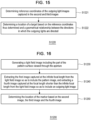
- FIG. 14 is a flowchart showing an optical tracking method (S1200) according to another embodiment of the present disclosure.
- S1200 optical tracking method
- a marker including a pattern surface and an aperture may be attached to a target.
- the marker 10 may be attached to an end portion of the surgical instrument 20. Further, the aperture 13 of the marker 10 may be arranged so as to face the image capturing device 100 at all times.
- step S1210 the posture of the marker is determined based on the first image 450 in which a part of the pattern surface viewed through the aperture is captured as a pattern image at an infinite focal length.
- step S1220 the location of the marker is determined based on the second and third images 460 and 470 in which the outgoing lights emitted in different directions through the aperture are captured as outgoing light images at a focal length shorter than the infinite focal length.
- the processor 440 can simultaneously determine the posture of the marker and the location of the marker. In another embodiment, the processor 440 may determine the location of the marker before determining the posture of the marker, or may determine the location of the marker after determining the posture of the marker.
- FIG. 14 is a flowchart showing a step S1210 of determining a posture of a marker in the optical tracking method shown in FIG. 13 .
- FIG. 15 is a flowchart showing a step S1220 of determining a location of a marker in the optical tracking method shown in FIG. 13 .
- the step S1210 may be performed as follows. Referring to FIG. 5 , first, the location of the pattern image 455 included in the first image 450 in the entire region of the pattern surface may be determined (S1211). Next, the posture of the target may be determined based on the location thus determined (S1212).
- the step S1220 may be performed as follows. First, the reference coordinates of the outgoing light images formed in the second and third images 460 and 470 may be respectively determined (S1221), and the location of the target may be determined using the reference coordinates thus determined and the geometrical relationship between the directions in which the outgoing lights are directed (S1222).
- the processor 440 may process and determine the location and the posture of the marker in parallel. That is, since the first to third images 450, 460 and 470 are simultaneously captured, the processor 440 may simultaneously determine the posture and the location of the target by processing the first to third images 450, 460 and 470 at a time.
- FIG. 16 is a flowchart showing an example in which a light field image is used in the optical tracking method shown in FIG. 13 .
- a light field image including a part of a pattern surface viewed through an aperture may be generated (S1230).
- a first image 550 captured at an infinite focal length and including a pattern image may be extracted from the light field image
- a fourth image 580 captured at a short focal length and including an outgoing light image may be extracted from the light field image (S1240).
- the location of the marker may be determined based on the second image, the third image and the fourth image 560, 570 and 580 (S1250).
- the processor may determine the location of the marker based on triangulation using the reference coordinates of the outgoing light images included in the three images and the geometric relationship between the directions in which the image capturing parts look at the marker.
- the location of the marker is determined using the triangulation.
- the present disclosure is not limited thereto. Methods other than the triangulation may be used.
- the method may also be embodied as computer-readable codes in a computer-readable recording medium.
- the computer-readable recording medium includes all kinds of recording devices that store data that can be read by a computer system. Examples of the computer-readable recording medium may include memory devices such as a CD-ROM, a USB and the like.
- the computer-readable recording medium may be distributed to computer systems that are connected through a network, and a computer-readable code may be stored and executed in a distributed manner.
- functional programs, codes, and code segments for implementing the embodiments above may be easily inferred by the programmers who are skilled in the art.
Description
- The present disclosure relates to a system and an optical tracking method.
- The present disclosure is derived from research conducted as a part of the Robot Industry Fusion Core Technology Development Project of the Ministry of Trade, Industry and Energy [Project No. 10062800, Project Title: Development of Practical Technology of Medical Imaging based Brain Surgery Robot System through Clinical Trial]
- An optical tracking system may be used for tracking a target. Recently, in order to perform precise surgery while minimizing a risk of the surgical errors, a method has been used that tracks the location (or coordinates) and the posture (or orientation) of a surgical robot or a surgical instrument and utilizes the tracking result for surgery. The location of a target, for example, may be defined as spatial coordinates, such as coordinates on the X, Y, and Z axes of an orthogonal coordinate system. The posture of a target may be defined as a roll, pitch, or yaw. In order to accurately track a target, it is important to accurately recognize the location and the posture of the target, which correspond to six degrees of freedom as described above.
- In the optical tracking system, for example, after attaching a reference body, such as a marker, to the target, the marker is tracked in order to determine the location and the posture of the target. The optical tracking system goes through, for example, a process in which a part of the marker is imaged using an image capturing device such as a camera or the like, and the image is read. In this process, a part of the captured image (for example, a boundary portion) may appear blurred or unclear due to various factors. When the marker is tracked based on such an image, there may be generated a difference between the estimated location and posture of the target and the actual location and posture of the target. "An image-based coordinate tracking system using afocal optics for surgical navigation", ISBN 978-3-319-05710-1, Y S Chae and
EP 3 151 196 are examples of an optical tracking system. - An embodiment of the present disclosure provides a system according to
claim 1 and an optical tracking method according toclaim 11 capable of accurately measuring the location and posture of a target. For example, an embodiment of the present disclosure may provide a system and an optical tracking method capable of capturing three images of a marker and measuring a location and a posture of a target based on the three image thus captured. - According to one aspect of the present disclosure, there is provided a system according to
claim 1. - In one embodiment, the processor is configured to determine the posture of the marker based on the first image in which the part of the pattern surface visible through the aperture is captured at the infinite focal length; and a location tracking part configured to determine the location of the marker based on the second and third images in which the outgoing lights emitted through the aperture in different directions are respectively captured at the focal length shorter than the infinite focal length.
- In one embodiment, the first image includes a pattern image captured at the infinite focal length so that a part of the pattern surface is identifiably captured in the pattern image, and the second and third images include outgoing light images captured at a focal length of a predetermined range including a location of the target so that outgoing lights directed in different directions are captured in the outgoing light of the pattern image from an entire region of the pattern surface and to determine a posture of the target based on the location of the determined pattern image.
- In one embodiment, the location tracking part may be configured to determine reference coordinates of the outgoing light images captured in the second and third images and to determine a location of the target based on the determined reference coordinates.
- In one embodiment, the location tracking part may be configured to determine the location of the marker on a three-dimensional space based on a disparity between the reference coordinates of the outgoing light images captured in the second and third images.
- In one embodiment, the system may further include: a first image capturing part formed of a light field camera for generating a light field image, wherein the first image capturing part may be configured to extract the first image captured at the infinite focal length from the light field image so as to include a pattern image.
- In one embodiment, the first image capturing part may be configured to extract a fourth image captured at the focal length shorter than the infinite focal length from the light field image so as to include an outgoing light image, and the processor may be configured to determine the location of the marker based on the second image, the third image and the fourth image.
- According to a further aspect of the present disclosure, there is provided an optical tracking method according to
claim 11. - In one embodiment, the determining the posture of the marker may include: determining a location of the pattern image included in the first image in an entire region of the pattern surface; and determining a posture of the target based on the location of the pattern image thus determined.
- In one embodiment, the determining the location of the marker may include: determining reference coordinates of the outgoing light images captured in the second and third images; and determining a location of the target based on the reference coordinates thus determined and a geometrical relationship between the directions in which the outgoing lights are directed.
- In one embodiment, the method may further include: generating a light field image including the part of the pattern surface viewed through the aperture; extracting the first image captured at the infinite focal length from the light field image so as to include the pattern image, and extracting a fourth image captured at the focal length shorter than the infinite focal length from the light field image so as to include an outgoing light image; and determining the location of the marker based on the second image, the third image and the fourth image.
- According to the embodiments of the present disclosure, it is possible to simultaneously track a posture and a location of a marker attached to a target.
- In addition, it is possible to improve the tracking accuracy of a posture and a location of a marker and to improve the precision of the optical tracking system.
- Embodiments of the inventive aspects of this disclosure will be understood with reference to the following detailed description, when read in conjunction with the accompanying drawings.
-
FIG. 1 is a view showing an example in which an optical tracking system is used for surgery according to an embodiment of the present disclosure. -
FIG. 2 is a block diagram of an optical tracking system according to an embodiment of the present disclosure. -
FIG. 3 is a view showing an example in which the reflection light emitted from an aperture of a marker is captured by an image capturing part in different directions in accordance with an embodiment of the present disclosure. -
FIG. 4 is a view for illustrating a corrected image obtained by image-processing an image captured in an image capturing part in accordance with an embodiment of the present disclosure. -
FIG. 5 is a view for illustrating a method of determining a posture and a location of a marker based on three images captured by three image capturing parts of an optical tracking system in accordance with an embodiment of the present disclosure. -
FIG. 6 is a view for illustrating an exemplary shape of a first image captured by a first image capturing part shown inFIG. 5 . -
FIG. 7 is a view for illustrating an exemplary shape of a second image captured by a second image capturing part shown inFIG. 5 . -
FIG. 8 is a view for illustrating an exemplary shape of a third image captured by a third image capturing part shown inFIG. 5 . -
FIG. 9 is a view illustrating an example in which one image capturing part of an optical tracking system according to an embodiment of the present disclosure is formed of a light field camera. -
FIG. 10 is a view for illustrating a method of determining a posture and a location of a marker based on the images captured by the three image capturing parts of the optical tracking system shown inFIG. 9 . -
FIG. 11 is a view showing an example in which two image capturing parts of an optical tracking system according to an embodiment of the present disclosure is formed of light field cameras. -
FIG. 12 is a view for illustrating a method of determining a posture and a location of a marker based on the images captured by the three image capturing parts of the optical tracking system shown inFIG. 11 . -
FIG. 13 is a flowchart showing an optical tracking method according to another embodiment of the present disclosure. -
FIG. 14 is a flowchart showing a step of determining a posture of a marker in the optical tracking method shown inFIG. 13 . -
FIG. 15 is a flowchart showing a step of determining a location of a marker in the optical tracking method shown inFIG. 13 . -
FIG. 16 is a flowchart showing an example in which a light field image is used in the optical tracking method shown inFIG. 13 . - Embodiments of the present disclosure are only examples that are illustrated for the purpose of explaining the present disclosure. The embodiments of the present disclosure may be conducted in various manners, and the present disclosure shall not be construed to be limited to the embodiments described below or to the detailed description of the embodiments.
- The term "part" used in the present disclosure may refer to a software element or a hardware element, such as FPGA (field-programmable gate array), ASIC (application specific integrated circuit), etc. The "part" is not limited to hardware and software. The "part" may be configured to be in a storage medium that can be addressed, and may be configured to reproduce one or more processors. Accordingly, as an example, the "part" includes elements, such as software elements, object-oriented software elements, class elements, task elements, etc., processors, functions, attributes, procedures, subroutines, program code segments, drivers, firmware, micro-codes, circuits, data, databases, data structures, tables, arrays, and variables. Functions that are provided in the elements and "part" may be combined into fewer elements and "parts," or may be further divided into additional elements and "parts."
- All the technical terms and scientific terms in the present disclosure include meanings or definitions that are commonly understood by those of ordinary skill in the art unless otherwise defined. All terms in the present disclosure are selected for the purpose of describing the present disclosure more clearly, and are not selected to limit the scope of the present disclosure.
- The singular expressions that are described in the present disclosure may encompass plural expressions unless otherwise stated, which will be also applied to the singular expressions recited in the claims.
- The expressions, such as "first," "second," etc., which are shown in various embodiments of the present disclosure, are used to separate a plurality of elements from each other, and are not intended to limit an order or importance of the corresponding elements.
- The expressions, such as "include" or "have," which are used in the present disclosure, should be appreciated as open-ended terms that include a possibility of including other embodiments unless particularly otherwise stated in the phrase or sentence that contains the corresponding expressions.
- In the present disclosure, the expression "based on" will be used to describe one or more factors that affect an act or operation of a decision or determination that is described in the phrase that contains the corresponding expression, and does not exclude additional factors that affect the act or operation of the decision or determination.
- In the present disclosure, the description that one element is "connected," or "coupled" to another element should be appreciated to indicate that one element may be directly connected, or coupled, to another element, and should be further understood that a new element may be interposed between one element and another element.
- Hereinafter, the embodiments of the present disclosure will be described in detail with reference to the accompanying drawings. The same reference numeral will be used for the same element throughout the drawings, and a duplicate description of the same element will be omitted.
-
FIG. 1 is a view showing an example in which anoptical tracking system 1 according to an embodiment of the present disclosure is used for surgery. - As shown, a doctor D may proceed with surgery for a patient P by using a
surgical instrument 20 and theoptical tracking system 1 which includes animage capturing device 100. Amarker 10 may be attached to thesurgical instrument 20 that is used by the doctor D, and anothermarker 30 may be attached to a target, such as an affected portion of the patient P. Theimage capturing device 100 of theoptical tracking system 1 captures and obtains a pattern image for the whole pattern or a part of a pattern formed on themarker 10 and/or 30. The pattern image may be captured in a partial region in a frame of an image that is outputted by an image sensor included in an image capturing part of theimage capturing device 100. - When the pattern image is obtained, one or more sub-patterns may be extracted from the pattern image as a basic unit constituting the pattern of the marker. In some embodiments, locations of the one or more extracted sub-patterns in the entire pattern may be determined, and the posture of the
marker 10 and/or 30 may be determined based on the determined locations of the sub-patterns in the entire pattern. In this case, the posture of themarker 10 and/or 30 may be referred to a relative three-dimensional direction or orientation of themarker 10 and/or 30 with respect to theimage capturing device 100. - In one embodiment, the
image capturing device 100 includes three image capturing parts, each of which may be, for example, a camera capable of capturing an image for at least a part of themarker 10 and/or 30. Specifically, each of the image capturing parts captures an image from the light that goes from an aperture of themarker 10 and/or 30 to each of the image capturing parts. - The location of one
marker 10 and/or 30 may be determined using triangulation based on two images having a stereoscopic relationship among the three images captured by three cameras. - When the location and the posture of the
marker 10 and/or 30 are obtained as described above, the location and the posture of a target to which themarker 10 and/or 30 is attached may be determined based on a geometrical relationship between themarker 10 and/or 30 and the target to which themarker 10 and/or 30 is attached. - As will be described in detail below, according to the
optical tracking system 1 according to an embodiment of the present disclosure, the location and the posture of the target corresponding to six degrees of freedom may be determined by using at least one marker. - According to the
optical tracking system 1 of the present disclosure, even when onemarker 10 is attached to thesurgical instrument 20 as a target, the location and the posture of the target may be tracked based on a pattern formed on themarker 10. Therefore, a light orsmall marker 10 may be attached to thesurgical instrument 20, and the doctor D may proceed with surgery by using thesurgical instrument 20 having the marker attached thereto without concerning about a size or weight of themarker 10. Although the marker and theoptical tracking system 1 according to the present disclosure are used in the surgery of a patient by a doctor in the embodiments described above, they may also be used in various other instances for determining the location and the posture of a target by using a marker. For example, the marker and the optical tracking system, according to the present disclosure, may be used for determining the location and the posture of a surgical instrument that is attached to a surgical robot when a patient undergoes surgery using the surgical robot. In another example, the marker and the optical tracking system, according to the present disclosure, may be used for determining the location and the posture of a specific instrument and/or target when a specific operation is performed with respect to the target using the instrument by an operator or surgical robot. Various embodiments of the marker and the optical tracking system of the present disclosure, which have been described through the examples ofFIGs. 1 and2 , will be described in more detail below. -
FIG. 2 depicts a block diagram of theoptical tracking system 1 according to an embodiment of the present disclosure. - In the
optical tracking system 1, animage capturing device 100 captures a plurality of images including a part of themarker 10, and aprocessor 140 may receive the plurality of images from theimage capturing device 100 and tracks the location and the posture of themarker 10 based on the plurality of images. - In one embodiment, the
marker 10 includes apattern surface 15 on which a pattern is formed, and anoptical system 12, such as lenses or the like, which is configured to allow at least a part of the pattern, which uniquely appears depending on a viewing direction from the outside of the marker, to be identified (or visually recognized) from the outside of themarker 10. - The
contour 11 of themarker 10 may have a shape that facilitates the installation of thepattern surface 15 and theoptical system 12 such as a lens or the like. For example, thecontour 11 of themarker 10 may have a curved shape as a whole. In this case, thepattern surface 15 on which a pattern is formed may be embodied on at least a part of the inner or outer surface having a curved shape. Theoptical system 12 may be embodied in anaperture 13 opposite to thepattern surface 15 on the inner surface having a curved shape and may have, for example, a curved shape. In another embodiment, thecontour 11 of themarker 10 may have a hexahedral or cylindrical shape. When thecontour 11 of themarker 10 has a cylindrical shape, theoptical system 12 may be provided in theaperture 13 formed on one end portion of the cylindrical shape, and thepattern surface 15 may be provided in the other end portion opposite to one end portion. In this configuration, the pattern formed on thepattern surface 15 may be visually recognized from the outside through theoptical system 12. - In one embodiment, when the
marker 10 is located within the field of view of theimage capturing device 100 and theoptical system 12 is arranged to face theimage capturing device 100, theimage capturing device 100 captures at least a part of thepattern surface 15 identified through theoptical system 12 positioned in theaperture 13. - In one embodiment, the
image capturing device 100 includes first to thirdimage capturing parts image capturing parts pattern surface 15 of themarker 10, and each of the remaining two image capturing parts (for example, the second and thirdimage capturing parts 120 and 130) captures an outgoing light coming from theaperture 13 of themarker 10. In addition, the first to thirdimage capturing parts - The optical system of the first
image capturing part 110 constitutes an infinite optical system together with theoptical system 12 formed in theaperture 13 of themarker 10. Furthermore, the optical system of the firstimage capturing part 110 may form a focal point at an infinite focal length. Accordingly, the firstimage capturing part 110 captures an image including a part of thepattern surface 15 visible through theaperture 13 of themarker 10. The optical system of each of the second and thirdimage capturing parts image capturing parts aperture 13 of themarker 10. - The infinite focal length may mean, for example, a length corresponding to a position considerably far away from the
marker 10 with respect to theimage capturing device 100. Furthermore, the focal length shorter than the infinite focal length (hereinafter referred to as "short focal length") may mean a focal length of a predetermined range including the location of a target. Since themarker 10 is attached to a target, the focal length shorter than the infinite focal length may be a focal length of a predetermined range including the location of themarker 10. - In one embodiment, each of the first to third
image capturing parts marker 10. The firstimage capturing part 110 may be disposed between the second and thirdimage capturing parts image capturing parts image capturing parts image capturing parts lenses image sensors image sensors lens - In one embodiment, the
lenses lenses lenses lenses - In one embodiment, each of the
image sensors image sensors image sensors - In one embodiment, each of the first to third
image capturing parts light source marker 10 or the pattern in order to enhance the light incident on theimage capturing device 100 through theoptical system 12 so that thepattern surface 15 can be well identified outside themarker 10. In this case, themarker 10 may operate as a passive marker. Each of the first to thirdimage capturing parts beam splitter light source marker 10 through thelens - In
FIG. 2 , thelight sources image capturing parts light sources image capturing device 100. According to another embodiment, the light sources may be installed inside themarker 10 so as to irradiate light toward the front or back surface of thepattern surface 15. In this case, themarker 10 may operate as an active marker. - In one embodiment, when the
optical tracking system 1 is operating within a surgical system such as a surgical navigation system or the like, themarker 10 may be attached to at least one target including a surgical tool, a portion of a surgical robot or an affected portion of a patient. When a plurality of markers is used, the locations and the postures of the markers may be tracked sequentially or simultaneously. - In one embodiment, the
processor 140 may include aposture tracking part 142 for determining the posture of themarker 10 based on a first image obtained by capturing a part of thepattern surface 15 viewed through theaperture 13 at an infinite focal length, alocation tracking part 141 for determining the location of themarker 10 based on second and third images respectively obtained by capturing the outgoing lights emitted through theaperture 13 in different directions at a short focal length, and anID distinguishing part 143 for distinguishing the markers attached to the respective targets through the IDs of the markers to track the locations and the postures of the markers. TheID distinguishing part 143 may distinguish the ID of themarker 10 from the pattern image included in the first image. - According to a further embodiment, the
optical tracking system 1 may track the locations and the postures of two markers having a predetermined geometrical relationship. For example, theoptical tracking system 1 may simultaneously track the locations and postures of themarker 10 attached to thesurgical instrument 20 shown inFIG. 1 and themarker 30 attached to the head of a patient. The optical tracking system may obtain pattern images of patterns formed on two markers, respectively, through the image capturing device. The locations of two markers may be determined based on the predetermined geometrical relationship and a relationship between the location of at least a part of the pattern on the pattern image and the location of at least the corresponding part of the pattern on each of the markers. The postures of the markers may be determined in the same manner as described above. - In one embodiment, the
marker 10 may be attached to a target whose location and posture are measured by theoptical tracking system 1, or may be implemented as the entirety or a part of the target. By measuring the location and posture of themarker 10, the location and posture of the target to which themarker 10 is attached may be measured. In addition, themarker 10 and the target may have a predetermined geometrical relationship. -
FIG. 3 is a view illustrating an example in which the reflection light emitted from the aperture of the marker is captured by the image capturing parts in different directions according to an embodiment of the present disclosure. - In one embodiment, the first
image capturing part 270 forms an infinite optical system together with themarker 210. Thepattern surface 250 on which apattern 255 is formed may be disposed inside themarker 210 such that a pattern image is transferred to the firstimage capturing part 270 through theoptical system 220 in the form of the outgoing light L1. The depth of field of the image sensor included in the firstimage capturing part 270 may be set so as to encompass a predetermined finite range at a point farther than the location of themarker 210 or at an infinite point so that a pattern image is formed by theoptical system 220 of themarker 210. In this case, the image sensor included in the firstimage capturing part 270 may capture a pattern image on a part of the pattern formed in themarker 210, regardless of whether the distance from themarker 210 is changed in response to the movement of themarker 210. In addition, the firstimage capturing part 270 may capture the pattern image without adjusting the depth of field or the magnification even when the marker moves away from or comes close to the firstimage capturing part 270. Therefore, if the infinite optical system is configured as described above, at least a part of the pattern may be identified from the pattern image captured by the firstimage capturing part 270, regardless of how far themarker 210 is located away from the image capturing device. In another embodiment, when thepattern surface 250 is disposed inside themarker 210, theoptical system 220 of themarker 210 constitutes an infinite optical system together with theoptical system lenses image capturing parts - In one embodiment, the second and third
image capturing parts aperture 230 of themarker 210 in different directions. That is to say, the light L2 and L3 reflected from themarker 210 may pass through thelenses image capturing parts image capturing parts lenses image capturing parts optical system 220 of themarker 210 may not form an infinite optical system. In this case, the pattern may not be captured in a readable form. Thelenses image capturing parts image capturing parts aperture 230. Thus, the position of the outgoing light captured in the second and third images may be clearly identified. - In one embodiment, the
pattern 255 is formed such that the location of each of the sub-patterns is uniquely determined throughout the entire pattern. Therefore, the information on the location of each sub-pattern in the entire pattern may be extracted from the pattern image of the pattern. Specifically, thepattern 255 may include aperiodic sequences that are repeatedly arranged. For example, each aperiodic sequence may be a Pseudo-Random Binary Sequence (PRBS), and more specifically, may be a De Bruijn Sequence. In this case, the "aperiodic sequence," as described above, may mean that it has a maximized auto-correlativity or a plurality of subsequences included in the corresponding sequence is not arranged in a periodic manner. In addition, thepattern 255 may be formed so as to provide the ID of the marker. -
FIG. 4 is a view for illustrating a correctedimage 300 obtained by image-processing an image captured in the image capturing part in accordance with an embodiment of the present disclosure. - In one embodiment, the image capturing part captures an image of at least a part of the pattern formed on the marker to determine the location and the posture of a target (for example, a surgical instrument) to which the marker is attached. There may be a predetermined geometrical relationship between the marker and the target. When the posture of the marker is tracked, the posture of the target may be tracked using the predetermined geometrical relationship with the target.
- The image capturing part constituting the infinite optical system together with the marker may acquire a corrected
image 300 by subjecting an original image (not shown) actually captured by the image sensor to predetermined image processing. The original image (not shown) is such that the periphery around the pattern portion is not completely dark and the objects located at the field of view of the image capturing device are blurred. The image processing may be, for example, an operation by which the difference between bright and dark portions in the captured image is enhanced. - In one embodiment, the corrected
image 300 may include apattern image 320 formed at a predetermined location. Animaginary boundary portion 330 surrounding thepattern image 320 may correspond to the location of the aperture of the marker and may distinguish thepattern image 320 and theperipheral portion 310. A sub-pattern 350 included in thepattern image 320 may be read through apattern window 340 in a posture determination part of the processor. After the original image (not shown) is subjected to the image processing, thepattern image 320 becomes prominent just like the correctedimage 300 shown inFIG. 4 . Theperipheral portion 310 becomes dark, and theboundary portion 330 is blurred. - The
peripheral portion 310 of the correctedimage 300 excluding thepattern image 320 is a portion that is relatively darker than the pattern surface of the marker corresponding to thepattern image 320 and may be captured in a imageless state (for example, a black-out state). That is, the image sensor of the image capturing device darkens the area having not depth of field and the area having a relatively small light amount. The darkened area may become theperipheral portion 310. In addition, the image sensor of the image capturing part constituting the infinite optical system together with the optical system of the marker has a depth of field set to a long distance or an infinite distance, whereby all the objects existing in a short distance falling within a marker operation range may be severely blurred. Moreover, thepattern image 320 may be strongly prominent within the correctedimage 300 because the outgoing light emitted from the aperture of the marker is relatively bright compared with the ambient light. If the light used for capturing the image of the marker is controlled through illumination and filtering, the difference in brightness between thepattern image 320 and theperipheral portion 310 may be larger in the correctedimage 300. - In one embodiment, when the image capturing part of the optical tracking system captures the
pattern image 320 using the outgoing light reflected from the pattern surface formed on the marker, the posture determination part of the processor may determine the posture of the marker based on the location in the entire pattern of each sub-pattern 350 included in thepattern image 320. For example, a part of thepattern 255 shown inFIG. 3 may be included in the capturedpattern image 320. The processor may receive the correctedimage 300 from the image capturing part and may identify the sub-pattern 350 through apattern window 340 in theread pattern image 320. The size of thepattern window 340 may be equal to or greater than the size of the sub-pattern 350. That is, the posture tracking part of the processor may determine the location of the corresponding sub-pattern in the entire pattern and may determine the posture of the marker based on the location of the sub-pattern thus determined. -
FIG. 5 is a view showing a method of determining a posture and a location of amarker 405 based on threeimages image capturing parts - In one embodiment, the
marker 405 includes a pattern surface and an aperture. The pattern surface may have a pattern formed thereon and may be at least partially formed into a curved surface. The aperture in which an optical system is formed may be configured so that at least a part of the pattern uniquely appearing depending on the external observation direction of themarker 405 can be identified outside themarker 405. - In one embodiment, the
marker 405 is positioned within a field of view of the first to thirdimage capturing parts image capturing parts third images marker 405 in different directions. In addition, the optical system of the firstimage capturing part 410 constitutes an infinite optical system together with the optical system of themarker 405. The firstimage capturing part 410 may capture afirst image 450 at an infinite focal length. The optical system of each of the second and thirdimage capturing parts image capturing parts third images - The depth of field of the
first image 450 may be formed in a predetermined finite range around a position corresponding to an infinite focal length. The depths of field of the second andthird images third images marker 405. - In one embodiment, the first to third
image capturing parts image capturing parts image capturing part 410 may be disposed between the second and thirdimage capturing parts FIG. 5 . In addition, at least two of the first to thirdimage capturing parts image capturing part 410 and the secondimage capturing part 420 may be the same as the spacing between the firstimage capturing part 410 and the thirdimage capturing part 430. In addition, the second and thirdimage capturing parts - In one embodiment, the first
image capturing part 410 constituting an infinite optical system together with themarker 405 may be disposed at a predetermined position so as to have a different height from the second and thirdimage capturing parts image capturing part 410 may be disposed at a position higher than the second and thirdimage capturing parts image capturing part 410 is disposed at a higher position in the Y axis direction than the base line connecting the second and thirdimage capturing parts - In one embodiment, the first
image capturing part 410 captures afirst image 450 including a part of the pattern surface in a state in which the firstimage capturing part 410 constitutes an infinite optical system together with themarker 405. Each of the second and thirdimage capturing parts third images marker 405. Therefore, in thefirst image 450, apattern image 455 may be readably captured. In the second andthird images aperture regions - In one embodiment, the posture tracking part of the
processor 440 may track the posture of the target based on thefirst image 450. Specifically, the posture tracking part may determine the location of a part of the pattern included in thefirst image 450 in the entire region of the pattern, and may determine the posture of the target based on the location thus determined. In one embodiment, the posture tracking part may read a sub-pattern included in a part of the pattern to determine the location of a part of the pattern. First, in order to extract information for the tracking of the marker from the pattern image captured in thefirst image 450, the posture tracking part may read sub-patterns from the pattern image. Then, the posture tracking part may calculate the location (coordinates) of each sub-pattern in the entire pattern. - In one embodiment, the location tracking part of the
processor 440 may track the location of the target based on the second andthird images aperture regions third images 

image capturing parts aperture regions aperture regions - In one embodiment, the location tracking part may determine the location of the marker using triangulation. For example, the location tracking part may extract reference coordinates of the
aperture regions third images image capturing parts image capturing parts V1 andV2 in which the second and thirdimage capturing parts -
FIG. 6 is a view illustrating the appearance of thefirst image 450 captured by the firstimage capturing part 410 shown inFIG. 5 . - The
first image 450 may be an image captured by the firstimage capturing part 410 that constitutes an infinite optical system together with themarker 405. Thefirst image 450 may include apattern image 455 including a portion of thepattern 255 shown inFIG. 3 and having a focal point formed in the portion of thepattern 255. When the firstimage capturing part 410 is disposed between the second and thirdimage capturing parts FIG. 5 , thepattern image 455 may be disposed in thefirst image 450 between the positions at which theaperture regions third imagers - The location of the
pattern image 455 in thefirst image 450 can be defined by the distance X1 in the horizontal direction and the distance Y1 in the vertical direction. The distance X1 in the horizontal direction may mean the shortest distance between the left end of thefirst image 450 and thepattern image 455. The distance Y1 in the vertical direction may mean the shortest distance between the upper end of thefirst image 450 and thepattern image 455. In addition, when the firstimage capturing part 410 is disposed at a different height from the ground surface than the second and thirdimage capturing parts pattern image 455 may differ from the vertical distance of theaperture regions - In the
first image 450, theboundary portion 456 surrounding thepattern image 455 may correspond to the aperture of the marker. The outgoing light emitted through the edge of the aperture of the marker may be captured by a camera in a blurred form due to diffraction, internal reflection, aperture vignetting, focal depth or the like. Since theboundary portion 456 is formed in a blurred state, theboundary portion 456 may not be distinguished from theperipheral portion 457. Further, theperipheral portion 457 is a portion that is relatively darker than thepattern image 455 and may be corrected in an imageless form (for example, a black-out state) in an image processing process. Therefore, when the location tracking part of theprocessor 440 measures the reference coordinates of thepattern image 455, an error may occur due to the phenomenon that theboundary portion 456 is captured in a blurred state. Thus, the location tracking part may track the location of the marker based on the reference coordinates of theaperture regions third images - In one embodiment, the posture tracking part of the
processor 440 shown in FIG. can read thepattern image 455 from thefirst image 450. Thus, the posture tracking part may determine the posture of the marker using thepattern image 455 and may track the posture of the target using the relative relationship between the marker and the target. In one embodiment, theprocessor 440 may extract at least one sub-pattern from thepattern image 455 through a pattern window, may calculate a location of the sub-pattern in the entire pattern, and may determine the posture of the marker based thereon. For example, theprocessor 440 may calculate the posture of the marker based on one sub-pattern. -
FIG. 7 is a view illustrating the appearance of thesecond image 460 captured by the secondimage capturing part 420 shown inFIG. 5 .FIG. 8 is a view illustrating the appearance of thethird image 470 captured by the thirdimage capturing part 430 shown inFIG. 5 . - The second and third
image capturing parts aperture region peripheral portion aperture region - In the second and
third images aperture regions peripheral portions aperture regions third images processor 440 may determine the boundaries distinguished from theperipheral portions aperture regions aperture regions third images aperture regions - The locations of the
aperture regions third images third images aperture regions third images aperture regions - Referring to
FIG. 5 , the secondimage capturing part 420 may be disposed at a position shifted in the X axis negative direction relative to the firstimage capturing part 410. Therefore, the distance X2 in the horizontal direction of theaperture region 465 of thesecond image 460 may be smaller than the distance X1 in the horizontal direction of thepattern image 455 of thefirst image 450. In addition, the secondimage capturing part 420 can be disposed at a lower or higher position from the ground surface than the firstimage capturing part 410. Therefore, the distance H2 in the vertical direction of theaperture region 465 of thesecond image 460 may be different from the distance H1 in the vertical direction of thepattern image 455 of thefirst image 450. - The third
image capturing part 430 may be disposed at a position shifted in the X axis positive direction relative to the firstimage capturing part 410. Thus, the distance X3 in the horizontal direction of theaperture region 455 of thethird image 470 may be larger than the distance X1 in the horizontal direction of thepattern image 455 of thefirst image 450. Furthermore, the thirdimage capturing part 430 may be disposed at a lower or higher position from the ground surface than the firstimage capturing part 410. Thus, the distance Y3 in the vertical direction of theaperture region 455 of thethird image 470 may be different from the distance Y1 in the vertical direction of thepattern image 455 of thefirst image 450. When the second and thirdimage capturing parts aperture regions third images - Since the second and third
image capturing parts aperture regions third images FIGS. 7 and 8 , the difference between the distance X2 in the horizontal direction and the distance X3 in the horizontal direction may indicate a positive value. In addition, the second and thirdimage capturing parts FIG. 5 , the second and thirdimage capturing parts processor 440 may determine the location of the marker based on the aforementioned difference and the predetermined distance Dx. - In one embodiment, referring to
FIG. 5 , the location tracking part of theprocessor 440 may determine the reference coordinates 466 and 476 of theaperture regions third images V1 andV2 in which the second and thirdimage capturing parts -
FIG. 9 is a view illustrating an example in which one image capturing part of an optical tracking system according to an embodiment of the present disclosure is formed of a light field camera.FIG. 10 is a view for illustrating a method of determining a posture and a location of a marker based on the images captured by the three image capturing parts of the optical tracking system shown inFIG. 9 . Descriptions of the contents overlapping with those described in the above embodiment will be omitted. - In one embodiment, the system includes a
marker 505 having apattern surface 507 and anoptical system 506 configured so that thepattern surface 507 is visible through theoptical system 506, animage capturing device 500 including a firstimage capturing part 510, a secondimage capturing part 520 and a thirdimage capturing part 530, and aprocessor 540 including alocation tracking part 541, aposture tracking part 542 and anID distinguishing part 543. The firstimage capturing part 510 may have a structure of a light field camera. The light field camera may be configured to post-determine a depth of field after capturing an image of a subject and to combine images having different depths of field. Thus, the image sensor of the light field camera may have post-determined variable depths of field. The light field image generated by the light field camera may include a plurality of unit images for storing the color information and the direction information of light together. - The first
image capturing part 510 having a structure of a light field camera may include a lens 511, animage sensor 512, and alens array 515 disposed between the lens 511 and theimage sensor 512 and provided with a plurality of micro-lenses. Theimage sensor 512 may be divided into regions corresponding to the respective micro-lenses. The light field camera implemented by the firstimage capturing part 510 may transmit to the processor 540 afirst image 550, which is obtained by synthesizing images with depths of field ranging from a long distance to an infinite distance, so as to clearly capture an image of a part of apattern surface 507 located at an infinite position. - In another embodiment, the first
image capturing part 510 may perform a refocusing process using a plurality of unit images. In the refocusing process, an image having a desired depth may be newly extracted by combining the desired depth of field among the pixels of the light field image and the color information of the pixels corresponding to the inversely calculated light path or direction. This makes it possible to generate afirst image 550 from which a pattern image is clearly identifiable. - The second and third
image capturing parts second image 560 and athird image 570 using the outgoing lights emitted from theoptical system 506 of themarker 505 in different directions. The lights reflected from themarker 505 may pass through thelenses image capturing parts image sensors lenses image capturing parts optical system 506 of themarker 505 may not constitute an infinite optical system. In this case, a part of thepattern surface 507 may not be captured in a readable form in the second andthird images aperture regions third images - In one embodiment, the
posture tracking part 542 of theprocessor 540 may track the posture of the target based on thefirst image 550. Specifically, theposture tracking part 542 may determine the location of a part of the pattern included in thefirst image 550 in the entire region of the pattern, and may determine the posture of the target based on the location thus determined. - The
location tracking part 541 of theprocessor 540 may determine the location of the marker using triangulation. The firstimage capturing part 510 having a structure of a light field camera may be configured to extract afourth image 580 captured at a short focal length to include an outgoing light image, from the captured light field image. In thefourth image 580, theaperture region 585 may be clearly captured so that the location of theaperture region 585 can be clearly identified. - In one embodiment, the
location tracking part 541 may extract the reference coordinates of theaperture regions fourth images image capturing parts location tracking part 541 may calculate the location of the marker using the three reference coordinates, the predetermined distances between the first to thirdimage capturing parts V1 ,V2 andV3 in which the first to thirdimage capturing parts -
FIG. 11 is a view showing an example in which two image capturing parts of an optical tracking system according to an embodiment of the present disclosure is formed of light field cameras.FIG. 12 is a view for illustrating a method of determining a posture and a location of a marker based on the images captured by the three image capturing parts of the optical tracking system shown inFIG. 11 . Descriptions of the contents overlapping with those described in the above embodiment will be omitted. - In one embodiment, the system includes a
marker 605 having apattern surface 607 and anoptical system 606 configured so that thepattern surface 607 is visible through theoptical system 606, animage capturing device 600 including a firstimage capturing part 610, a secondimage capturing part 620 and a thirdimage capturing part 630, and aprocessor 640 including alocation tracking part 641, aposture tracking part 642 and anID distinguishing part 643. Each of the first and secondimage capturing parts - Each of the first and second
image capturing parts lens image sensor lens array lens image sensor image sensor image capturing parts first image 650 and/or afifth image 690, which is obtained by synthesizing images with depths of field ranging from a long distance to an infinite distance, so as to clearly capture an image of a part of apattern surface 607 located at an infinite position. - The second and third
image capturing parts second image 660 and athird image 670 using the outgoing lights emitted in different directions from theaperture 606 of themarker 605. In one embodiment, the secondimage capturing part 620 may transmit to theprocessor 640 thesecond image 660 extracted from the captured light field image so as to be captured at a short focal length. The light reflected from themarker 605 may pass through thelenses image capturing parts image sensors aperture regions third images - In one embodiment, the
posture tracking part 642 of theprocessor 640 may track the posture of the target based on thepattern image 655 captured in thefirst image 650. In another embodiment, theposture tracking part 642 may track the posture of the target based on thepattern image 695 captured in thefifth image 690. Specifically, theposture tracking part 642 may determine the location of a part of the pattern included in thefirst image 650 or thefifth image 690 in the entire region of the pattern, and may determine the posture of the target based on the location thus determined. In a further embodiment, theposture tracking part 642 may track the posture of the target based on an average value of the posture of the target determined based on thefirst image 650 and the posture of the target determined based on thefifth image 690. - In one embodiment, the
location tracking part 641 of theprocessor 640 may determine the location of the marker using triangulation. The firstimage capturing part 610 having a structure of a light field camera may be configured to extract afourth image 680 captured at a short focal length from a captured light field image so as to include an outgoing light image. In thefourth image 680, theaperture region 685 may be clearly captured so that the position of theaperture region 685 can be clearly identified. For example, thelocation tracking part 641 may extract the reference coordinates of theaperture regions fourth images image capturing parts location tracking part 641 may calculate the location of the marker using the three reference coordinates, the predetermined distances between the first to thirdimage capturing parts V1 ,V2 andV3 in which the first to thirdimage capturing parts -
FIG. 14 is a flowchart showing an optical tracking method (S1200) according to another embodiment of the present disclosure. Hereinafter, the respective steps of a marker tracking method will be described in more detail with reference to the drawings. - A marker including a pattern surface and an aperture may be attached to a target. Referring to
FIGS. 1 and2 , themarker 10 may be attached to an end portion of thesurgical instrument 20. Further, theaperture 13 of themarker 10 may be arranged so as to face theimage capturing device 100 at all times. - First, referring to
FIG. 5 , in step S1210, the posture of the marker is determined based on thefirst image 450 in which a part of the pattern surface viewed through the aperture is captured as a pattern image at an infinite focal length. In the next step S1220, the location of the marker is determined based on the second andthird images - In the optical tracking method (S1200), the
processor 440 can simultaneously determine the posture of the marker and the location of the marker. In another embodiment, theprocessor 440 may determine the location of the marker before determining the posture of the marker, or may determine the location of the marker after determining the posture of the marker. -
FIG. 14 is a flowchart showing a step S1210 of determining a posture of a marker in the optical tracking method shown inFIG. 13 .FIG. 15 is a flowchart showing a step S1220 of determining a location of a marker in the optical tracking method shown inFIG. 13 . - In one embodiment, the step S1210 may be performed as follows. Referring to
FIG. 5 , first, the location of thepattern image 455 included in thefirst image 450 in the entire region of the pattern surface may be determined (S1211). Next, the posture of the target may be determined based on the location thus determined (S1212). - In one embodiment, the step S1220 may be performed as follows. First, the reference coordinates of the outgoing light images formed in the second and
third images - In one embodiment, the
processor 440 may process and determine the location and the posture of the marker in parallel. That is, since the first tothird images processor 440 may simultaneously determine the posture and the location of the target by processing the first tothird images -
FIG. 16 is a flowchart showing an example in which a light field image is used in the optical tracking method shown inFIG. 13 . - Referring to
FIG. 10 , first, a light field image including a part of a pattern surface viewed through an aperture may be generated (S1230). Next, afirst image 550 captured at an infinite focal length and including a pattern image may be extracted from the light field image, and afourth image 580 captured at a short focal length and including an outgoing light image may be extracted from the light field image (S1240). Next, the location of the marker may be determined based on the second image, the third image and thefourth image - In step S1250, the processor may determine the location of the marker based on triangulation using the reference coordinates of the outgoing light images included in the three images and the geometric relationship between the directions in which the image capturing parts look at the marker. In the above embodiments, the location of the marker is determined using the triangulation. However, the present disclosure is not limited thereto. Methods other than the triangulation may be used.
- Although the method has been described through specific embodiments, the method may also be embodied as computer-readable codes in a computer-readable recording medium. The computer-readable recording medium includes all kinds of recording devices that store data that can be read by a computer system. Examples of the computer-readable recording medium may include memory devices such as a CD-ROM, a USB and the like. In addition, the computer-readable recording medium may be distributed to computer systems that are connected through a network, and a computer-readable code may be stored and executed in a distributed manner. In addition, functional programs, codes, and code segments for implementing the embodiments above may be easily inferred by the programmers who are skilled in the art.
- Although the present disclosure has been described in relation to some embodiments, it should be noted that there may be various modifications and changes without departing from the scope of the present disclosure, which can be understood by those skilled in the art. The invention is defined by the appended claims.
Claims (14)
- A system comprising:a marker (10, 30, 210, 405, 505, 605) which is attachable to a target and configured so that a pattern surface (15, 250, 507, 607) formed inside the marker (10, 30, 210, 405, 505, 605) is visible through an optical system (12, 220, 506, 606) formed in an aperture (13, 230) of the marker (10, 30, 210, 405, 505, 605); andan optical tracking system (1) for tracking a location and a posture of a the marker (10, 30, 210, 405, 505, 605),wherein the optical tracking system (1) comprises a first image capturing part (110, 270, 410, 510, 610) configured to capture a first image (450, 550, 650) including a pattern image (320, 455, 655) in which a part of the pattern surface (15, 250, 507, 607) is identifiably captured, the first image capturing part (110, 270, 410, 510, 610) forming an infinite optical system together with the marker (10, 30, 210, 405, 505, 605),characterized in that the optical tracking system (1) further comprises:a second image capturing part (120, 280, 420, 520, 620) configured to capture a second image (460, 560, 660) including an outgoing light image of an outgoing light emitted through the aperture (13, 230) in a first direction;a third image capturing part (130, 290, 430, 530, 630) configured to capture a third image (470, 570, 670) including an outgoing light image of an outgoing light emitted through the aperture (13, 230) in a second direction differing from the first direction, anda processor (140, 440, 540, 640) configured to determine the posture of the marker (10, 30, 210, 405, 505, 605) based on the first image (450, 550, 650), and to determine the location of the marker (10, 30, 210, 405, 505, 605) based on the second image (460, 560, 660) and the third image (470, 570, 670),wherein the depths of field of the second and third images (460, 560, 660; 470, 570, 670) are formed in a predetermined finite range around the location of the marker (10, 30, 210, 405, 505, 605).
- The system of Claim 1, wherein the processor (140, 440, 540, 640) includes:a posture tracking part (142, 542, 642) configured to determine the posture of the marker (10, 30, 210, 405, 505, 605) based on the first image (450, 550, 650); anda location tracking part (141, 541, 641) configured to determine the location of the marker (10, 30, 210, 405, 505, 605) based on the second and third images (460, 560, 660; 470, 570, 670) in which the outgoing lights emitted through the aperture (13, 230) in different directions are respectively captured.
- The system of Claim 1, wherein the second and third images (460, 560, 660; 470, 570, 670) respectively include outgoing light images captured so that the outgoing lights directed in different directions are captured in the outgoing light images.
- The system of Claim 2, wherein the posture tracking part (142, 542, 642) is configured to determine a location of the pattern image (320, 455, 655) from an entire region of the pattern surface (15, 250, 507, 607) and to determine a posture of the target based on the determined location of the pattern image (320, 455, 655).
- The system of Claim 3, wherein the processor (140, 440, 540, 640) includes a location tracking part (141, 541, 641) configured to determine reference coordinates of the outgoing light images captured in the second and third images (460, 560, 660; 470, 570, 670) and to determine a location of the target based on the determined reference coordinates.
- The system of Claim 5, wherein the location tracking part (141, 541, 641) is configured to determine the location of the marker (10, 30, 210, 405, 505, 605) in a three-dimensional space based on a disparity between the reference coordinates of the outgoing light images captured in the second and third images (460, 560, 660; 470, 570, 670).
- The system of Claim 1,wherein the first image capturing part (110, 270, 410, 510, 610) consists of a light field camera for generating a light field image, and
wherein the first image capturing part (110, 270, 410, 510, 610) is configured to extract the first image (450, 550, 650) captured from the light field image so as to include the pattern image (320, 455, 655). - The system of Claim 7, wherein the first image capturing part (110, 270, 410, 510, 610) is configured to extract a fourth image (580, 680) captured from the light field image so as to include an outgoing light image,an aperture region (585, 685) is captured in the fourth image (580, 680) so that a position of the aperture region (585, 685) can be clearly identified, andthe processor (140, 440, 540, 640) is configured to determine the location of the marker (10, 30, 210, 405, 505, 605) based on the second image (460, 560, 660), the third image (470, 570, 670) and the fourth image (580, 680).
- The system of Claim 1, wherein each of the first image capturing part (110, 270, 410, 510, 610) and the second image capturing part (120, 280, 420, 520, 620) consists of a light field camera for generating a light field image,the first image capturing part (110, 270, 410, 510, 610) is configured to extract a fourth image (580, 680) captured from the light field image,the aperture (13, 230) is captured in the fourth image (580, 680) so that a position of the aperture (13, 230) can be clearly identified,the second image capturing part (120, 280, 420, 520, 620) is configured to extract the second image (460, 560, 660) captured from the light field image, andthe processor (140, 440, 540, 640) is configured to determine the location of the marker (10, 30, 210, 405, 505, 605) based on the second image (460, 560, 660), the third image (470, 570, 670) and the fourth image (580, 680).
- The system of Claim 1, wherein the first image capturing part (110, 270, 410, 510, 610) is disposed at a height different from a height of the second and third image capturing parts (120, 280, 420, 520, 620; 130, 290, 430, 530, 630) from a ground surface, and is disposed between the second and third image capturing parts (120, 280, 420, 520, 620; 130, 290, 430, 530, 630) in a plan view.
- An optical tracking method (S1200) for tracking a location and a posture of a marker (10, 30, 210, 405, 505, 605) which is attachable to a target and configured so that a pattern surface (15, 250, 507, 607) formed inside the marker (10, 30, 210, 405, 505, 605) is visible through an optical system (12, 220, 506, 606) formed in an aperture (13, 230) of the marker (10, 30, 210, 405, 505, 605) comprising:determining the posture of the marker (10, 30, 210, 405, 505, 605) based on a first image, which is captured by a first image capturing part (110, 270, 410, 510, 610), which forms an infinite optical system together with the marker (10, 30, 210, 405, 505, 605), including a pattern image (320, 455, 655) in which a part of the pattern surface (15, 250, 507, 607) is identifiably captured,characterized in that the optical tracking method (S1200) further comprises:determining the location of the marker (10, 30, 210, 405, 505, 605) based on a second image (460, 560, 660) and a third image (470, 570, 670),wherein the second image (460, 560, 660) is captured by a second image capturing part (120, 280, 420, 520, 620) and includes an outgoing light image of an outgoing light emitted through the aperture (13, 230) in a first direction,wherein the third image (470, 570, 670) is captured by a third image capturing part (130, 290, 430, 530, 630) and includes an outgoing light image of an outgoing light emitted through the aperture (13, 230) in a second direction differing from the first direction,wherein the depths of field of the second and third images (460, 560, 660; 470, 570, 670) are formed in a predetermined finite range around the location of the marker (10, 30, 210, 405, 505, 605).
- The optical tracking method (S1200) of Claim 11, wherein the determining the posture of the marker (10, 30, 210, 405, 505, 605) includes:determining a location of the pattern image (320, 455, 655) included in the first image (450, 550, 650) in an entire region of the pattern surface (15, 250, 507, 607); anddetermining a posture of the target based on the location of the pattern image (320, 455, 655) thus determined.
- The optical tracking method (S1200) of Claim 11, wherein the determining the location of the marker (10, 30, 210, 405, 505, 605) includes:determining reference coordinates of the outgoing light images captured in the second and third images (460, 560, 660; 470, 570, 670); anddetermining a location of the target based on the reference coordinates thus determined and a geometrical relationship between the directions in which the outgoing lights are directed.
- The optical tracking method (S1200) of Claim 11, further comprising:generating a light field image including the part of the pattern surface (15, 250, 507, 607) viewed through the aperture (13, 230);extracting the first image (450, 550, 650) captured from the light field image so as to include the pattern image (320, 455, 655);extracting a fourth image (580, 680) captured from the light field image so as to include an outgoing light image, wherein the aperture (13, 230) is captured in the fourth image (580, 680) so that a position of the aperture (13, 230) can be clearly identified; anddetermining the location of the marker (10, 30, 210, 405, 505, 605) based on the second image (460, 560, 660), the third image (470, 570, 670) and the fourth image (580, 680).
Priority Applications (1)
| Application Number | Priority Date | Filing Date | Title |
|---|---|---|---|
| EP23192558.7A EP4273805A3 (en) | 2017-12-20 | 2017-12-22 | Optical tracking system and optical tracking method |
Applications Claiming Priority (1)
| Application Number | Priority Date | Filing Date | Title |
|---|---|---|---|
| KR1020170176503A KR102166372B1 (en) | 2017-12-20 | 2017-12-20 | Optical tracking system and optical tracking method |
Related Child Applications (2)
| Application Number | Title | Priority Date | Filing Date |
|---|---|---|---|
| EP23192558.7A Division-Into EP4273805A3 (en) | 2017-12-20 | 2017-12-22 | Optical tracking system and optical tracking method |
| EP23192558.7A Division EP4273805A3 (en) | 2017-12-20 | 2017-12-22 | Optical tracking system and optical tracking method |
Publications (3)
| Publication Number | Publication Date |
|---|---|
| EP3503033A1 EP3503033A1 (en) | 2019-06-26 |
| EP3503033B1 true EP3503033B1 (en) | 2023-10-04 |
| EP3503033C0 EP3503033C0 (en) | 2023-10-04 |
Family
ID=60953602
Family Applications (2)
| Application Number | Title | Priority Date | Filing Date |
|---|---|---|---|
| EP23192558.7A Pending EP4273805A3 (en) | 2017-12-20 | 2017-12-22 | Optical tracking system and optical tracking method |
| EP17210446.5A Active EP3503033B1 (en) | 2017-12-20 | 2017-12-22 | Optical tracking system and optical tracking method |
Family Applications Before (1)
| Application Number | Title | Priority Date | Filing Date |
|---|---|---|---|
| EP23192558.7A Pending EP4273805A3 (en) | 2017-12-20 | 2017-12-22 | Optical tracking system and optical tracking method |
Country Status (5)
| Country | Link |
|---|---|
| US (2) | US10692239B2 (en) |
| EP (2) | EP4273805A3 (en) |
| JP (1) | JP6475311B1 (en) |
| KR (1) | KR102166372B1 (en) |
| CN (2) | CN109938837B (en) |
Families Citing this family (10)
| Publication number | Priority date | Publication date | Assignee | Title |
|---|---|---|---|---|
| KR102166372B1 (en) * | 2017-12-20 | 2020-10-15 | 주식회사 고영테크놀러지 | Optical tracking system and optical tracking method |
| GB2586601B (en) * | 2019-08-27 | 2022-10-12 | Zeta Motion Ltd | Determining object pose from image data |
| US11382699B2 (en) * | 2020-02-10 | 2022-07-12 | Globus Medical Inc. | Extended reality visualization of optical tool tracking volume for computer assisted navigation in surgery |
| US11819302B2 (en) | 2021-03-31 | 2023-11-21 | Moon Surgical Sas | Co-manipulation surgical system having user guided stage control |
| US11812938B2 (en) | 2021-03-31 | 2023-11-14 | Moon Surgical Sas | Co-manipulation surgical system having a coupling mechanism removeably attachable to surgical instruments |
| WO2023281372A2 (en) * | 2021-07-05 | 2023-01-12 | Moon Surgical Sas | Co-manipulation surgical system having optical scanners for use with surgical instruments for performing laparoscopic surgery |
| WO2022208414A1 (en) | 2021-03-31 | 2022-10-06 | Moon Surgical Sas | Co-manipulation surgical system for use with surgical instruments for performing laparoscopic surgery |
| US11832909B2 (en) | 2021-03-31 | 2023-12-05 | Moon Surgical Sas | Co-manipulation surgical system having actuatable setup joints |
| US11844583B2 (en) | 2021-03-31 | 2023-12-19 | Moon Surgical Sas | Co-manipulation surgical system having an instrument centering mode for automatic scope movements |
| US11839442B1 (en) | 2023-01-09 | 2023-12-12 | Moon Surgical Sas | Co-manipulation surgical system for use with surgical instruments for performing laparoscopic surgery while estimating hold force |
Family Cites Families (17)
| Publication number | Priority date | Publication date | Assignee | Title |
|---|---|---|---|---|
| JP2008026236A (en) * | 2006-07-24 | 2008-02-07 | Olympus Corp | Position and attitude measuring instrument, and position and attitude measuring method |
| JP2008216089A (en) | 2007-03-06 | 2008-09-18 | Natl Inst Of Radiological Sciences | Instrument for measuring three-dimensional position and direction of specimen |
| GB201208088D0 (en) * | 2012-05-09 | 2012-06-20 | Ncam Sollutions Ltd | Ncam |
| JP6443934B2 (en) | 2012-07-01 | 2018-12-26 | ルミト・アーベー | System for improved diffuse luminescence imaging or tomography in scattering media |
| KR101487248B1 (en) * | 2013-05-28 | 2015-01-29 | 주식회사 고영테크놀러지 | Optical tracking system |
| KR101487251B1 (en) * | 2013-05-28 | 2015-01-28 | 주식회사 고영테크놀러지 | Optical tracking system and method for tracking using the same |
| KR101406220B1 (en) | 2013-04-30 | 2014-06-12 | 경북대학교 산학협력단 | Optical tracking system and method for tracking using the same |
| EP2992852B1 (en) | 2013-04-30 | 2018-03-07 | Koh Young Technology Inc. | Optical tracking system and detection method |
| KR101613418B1 (en) * | 2014-05-29 | 2016-04-21 | 주식회사 고영테크놀러지 | Optical tracking system and method of calculating orientation and location of marker part of optical tracking system |
| KR101615086B1 (en) | 2014-05-29 | 2016-04-27 | 주식회사 고영테크놀러지 | Optical tracking system and method of calculating orientation of marker part of optical tracking system |
| KR101627835B1 (en) * | 2015-07-24 | 2016-06-08 | 주식회사 고영테크놀러지 | Optical tracking system and method |
| CN108697367A (en) * | 2015-11-23 | 2018-10-23 | 凯内蒂科尓股份有限公司 | Systems, devices and methods for patient motion to be tracked and compensated during medical image scan |
| KR20160039588A (en) * | 2016-03-22 | 2016-04-11 | 주식회사 우리옵토 | Micro-pattern formaing method on optical lenz having a certain curvature |
| JP6211137B2 (en) * | 2016-06-02 | 2017-10-11 | キヤノン株式会社 | Image processing apparatus, imaging apparatus, and image processing method |
| KR101820682B1 (en) | 2016-08-09 | 2018-01-23 | 주식회사 고영테크놀러지 | Marker for optical tracking, optical tracking system, and optical tracking method |
| KR102166372B1 (en) * | 2017-12-20 | 2020-10-15 | 주식회사 고영테크놀러지 | Optical tracking system and optical tracking method |
| KR102102291B1 (en) * | 2017-12-20 | 2020-04-21 | 주식회사 고영테크놀러지 | Optical tracking system and optical tracking method |
-
2017
- 2017-12-20 KR KR1020170176503A patent/KR102166372B1/en active IP Right Grant
- 2017-12-22 EP EP23192558.7A patent/EP4273805A3/en active Pending
- 2017-12-22 JP JP2017246445A patent/JP6475311B1/en active Active
- 2017-12-22 CN CN201711404643.2A patent/CN109938837B/en active Active
- 2017-12-22 CN CN202111096827.3A patent/CN113813046A/en active Pending
- 2017-12-22 EP EP17210446.5A patent/EP3503033B1/en active Active
- 2017-12-22 US US15/852,610 patent/US10692239B2/en active Active
-
2020
- 2020-05-15 US US16/875,311 patent/US11436750B2/en active Active
Non-Patent Citations (2)
| Title |
|---|
| ANONYMOUS: "Triangulation (computer vision)", INTERNET CITATION, 13 November 2011 (2011-11-13), pages 1 - 2, XP002703957, Retrieved from the Internet <URL:http://en.wikipedia.org/w/index.php?title=Triangulation_%28computer_vision%29&oldid=460469006> [retrieved on 20130719] * |
| CHRISTIAN JANSEN ET AL: "Performance Improvement for Optical Tracking by Adapting Marker Arrangements", 10 March 2007 (2007-03-10), pages 28 - 33, XP002679938, Retrieved from the Internet <URL:http://viscg.uni-muenster.de/publications/2007/JSHVS07/> [retrieved on 20200724] * |
Also Published As
| Publication number | Publication date |
|---|---|
| JP2019113393A (en) | 2019-07-11 |
| CN109938837A (en) | 2019-06-28 |
| EP3503033A1 (en) | 2019-06-26 |
| US10692239B2 (en) | 2020-06-23 |
| KR102166372B1 (en) | 2020-10-15 |
| CN109938837B (en) | 2021-10-15 |
| KR20190074841A (en) | 2019-06-28 |
| EP3503033C0 (en) | 2023-10-04 |
| EP4273805A2 (en) | 2023-11-08 |
| US20200279394A1 (en) | 2020-09-03 |
| JP6475311B1 (en) | 2019-02-27 |
| CN113813046A (en) | 2021-12-21 |
| US20190188877A1 (en) | 2019-06-20 |
| US11436750B2 (en) | 2022-09-06 |
| EP4273805A3 (en) | 2024-02-28 |
Similar Documents
| Publication | Publication Date | Title |
|---|---|---|
| EP3503033B1 (en) | Optical tracking system and optical tracking method | |
| EP3503032B1 (en) | Optical tracking system and optical tracking method | |
| US10219866B2 (en) | Optical tracking method and system based on passive markers | |
| EP3281600B1 (en) | Marker for optical tracking, optical tracking system, and optical tracking method | |
| CN103702607B (en) | The calibration of the coordinate system of camera system and conversion | |
| US20150301179A1 (en) | Method and device for determining an orientation of an object | |
| JP2011516849A (en) | 3D imaging system | |
| CN113034612B (en) | Calibration device, method and depth camera | |
| JP2012215394A (en) | Three-dimensional measuring apparatus and three-dimensional measuring method | |
| CN109143167B (en) | Obstacle information acquisition device and method | |
| KR102253350B1 (en) | Optical tracking system and optical tracking method | |
| KR100698535B1 (en) | Position recognition device and method of mobile robot with tilt correction function | |
| JP3925129B2 (en) | Three-dimensional imaging apparatus and method | |
| Abbaspour Tehrani et al. | A practical method for fully automatic intrinsic camera calibration using directionally encoded light | |
| JP2018160145A (en) | Three-dimensional measurement device, three-dimensional measurement program, and three-dimensional measurement system | |
| WO2014109146A1 (en) | Three dimensional measuring device | |
| WO2023062370A1 (en) | System and method for automatic calibration and alignment of fundus camera device | |
| CN115830109A (en) | Method, device and equipment for evaluating quality of reflective marker and storage medium | |
| CN117640915A (en) | Laser scanner with stereoscopic camera field of view for improved selective feature scanning | |
| CN103886575A (en) | Three-dimensional positioning device based on machine vision technology | |
| CN117876498A (en) | Compensation method and device for calibration data, and calibration method and device |
Legal Events
| Date | Code | Title | Description |
|---|---|---|---|
| PUAI | Public reference made under article 153(3) epc to a published international application that has entered the european phase |
Free format text: ORIGINAL CODE: 0009012 |
|
| STAA | Information on the status of an ep patent application or granted ep patent |
Free format text: STATUS: REQUEST FOR EXAMINATION WAS MADE |
|
| 17P | Request for examination filed |
Effective date: 20180118 |
|
| AK | Designated contracting states |
Kind code of ref document: A1 Designated state(s): AL AT BE BG CH CY CZ DE DK EE ES FI FR GB GR HR HU IE IS IT LI LT LU LV MC MK MT NL NO PL PT RO RS SE SI SK SM TR |
|
| AX | Request for extension of the european patent |
Extension state: BA ME |
|
| RBV | Designated contracting states (corrected) |
Designated state(s): AL AT BE BG CH CY CZ DE DK EE ES FI FR GB GR HR HU IE IS IT LI LT LU LV MC MK MT NL NO PL PT RO RS SE SI SK SM TR |
|
| STAA | Information on the status of an ep patent application or granted ep patent |
Free format text: STATUS: EXAMINATION IS IN PROGRESS |
|
| 17Q | First examination report despatched |
Effective date: 20200129 |
|
| STAA | Information on the status of an ep patent application or granted ep patent |
Free format text: STATUS: EXAMINATION IS IN PROGRESS |
|
| STAA | Information on the status of an ep patent application or granted ep patent |
Free format text: STATUS: EXAMINATION IS IN PROGRESS |
|
| GRAP | Despatch of communication of intention to grant a patent |
Free format text: ORIGINAL CODE: EPIDOSNIGR1 |
|
| STAA | Information on the status of an ep patent application or granted ep patent |
Free format text: STATUS: GRANT OF PATENT IS INTENDED |
|
| INTG | Intention to grant announced |
Effective date: 20230426 |
|
| GRAS | Grant fee paid |
Free format text: ORIGINAL CODE: EPIDOSNIGR3 |
|
| GRAA | (expected) grant |
Free format text: ORIGINAL CODE: 0009210 |
|
| STAA | Information on the status of an ep patent application or granted ep patent |
Free format text: STATUS: THE PATENT HAS BEEN GRANTED |
|
| AK | Designated contracting states |
Kind code of ref document: B1 Designated state(s): AL AT BE BG CH CY CZ DE DK EE ES FI FR GB GR HR HU IE IS IT LI LT LU LV MC MK MT NL NO PL PT RO RS SE SI SK SM TR |
|
| REG | Reference to a national code |
Ref country code: GB Ref legal event code: FG4D |
|
| REG | Reference to a national code |
Ref country code: CH Ref legal event code: EP |
|
| REG | Reference to a national code |
Ref country code: DE Ref legal event code: R096 Ref document number: 602017074862 Country of ref document: DE |
|
| REG | Reference to a national code |
Ref country code: IE Ref legal event code: FG4D |
|
| U01 | Request for unitary effect filed |
Effective date: 20231005 |
|
| U07 | Unitary effect registered |
Designated state(s): AT BE BG DE DK EE FI FR IT LT LU LV MT NL PT SE SI Effective date: 20231016 |
|
| U20 | Renewal fee paid [unitary effect] |
Year of fee payment: 7 Effective date: 20231117 |
|
| PG25 | Lapsed in a contracting state [announced via postgrant information from national office to epo] |
Ref country code: GR Free format text: LAPSE BECAUSE OF FAILURE TO SUBMIT A TRANSLATION OF THE DESCRIPTION OR TO PAY THE FEE WITHIN THE PRESCRIBED TIME-LIMIT Effective date: 20240105 |
|
| PG25 | Lapsed in a contracting state [announced via postgrant information from national office to epo] |
Ref country code: IS Free format text: LAPSE BECAUSE OF FAILURE TO SUBMIT A TRANSLATION OF THE DESCRIPTION OR TO PAY THE FEE WITHIN THE PRESCRIBED TIME-LIMIT Effective date: 20240204 |