EP3502830A1 - Apparatus for mounting processors for cluster computing - Google Patents
Apparatus for mounting processors for cluster computing Download PDFInfo
- Publication number
- EP3502830A1 EP3502830A1 EP18214527.6A EP18214527A EP3502830A1 EP 3502830 A1 EP3502830 A1 EP 3502830A1 EP 18214527 A EP18214527 A EP 18214527A EP 3502830 A1 EP3502830 A1 EP 3502830A1
- Authority
- EP
- European Patent Office
- Prior art keywords
- bracket
- arm
- processor
- base portion
- aperture
- Prior art date
- Legal status (The legal status is an assumption and is not a legal conclusion. Google has not performed a legal analysis and makes no representation as to the accuracy of the status listed.)
- Granted
Links
Images



Classifications
-
- H—ELECTRICITY
- H05—ELECTRIC TECHNIQUES NOT OTHERWISE PROVIDED FOR
- H05K—PRINTED CIRCUITS; CASINGS OR CONSTRUCTIONAL DETAILS OF ELECTRIC APPARATUS; MANUFACTURE OF ASSEMBLAGES OF ELECTRICAL COMPONENTS
- H05K7/00—Constructional details common to different types of electric apparatus
- H05K7/14—Mounting supporting structure in casing or on frame or rack
- H05K7/1485—Servers; Data center rooms, e.g. 19-inch computer racks
- H05K7/1487—Blade assemblies, e.g. blade cases or inner arrangements within a blade
-
- G—PHYSICS
- G06—COMPUTING OR CALCULATING; COUNTING
- G06F—ELECTRIC DIGITAL DATA PROCESSING
- G06F1/00—Details not covered by groups G06F3/00 - G06F13/00 and G06F21/00
- G06F1/16—Constructional details or arrangements
- G06F1/18—Packaging or power distribution
- G06F1/183—Internal mounting support structures, e.g. for supporting printed circuit boards
- G06F1/184—Mounting of motherboards
-
- G—PHYSICS
- G06—COMPUTING OR CALCULATING; COUNTING
- G06F—ELECTRIC DIGITAL DATA PROCESSING
- G06F1/00—Details not covered by groups G06F3/00 - G06F13/00 and G06F21/00
- G06F1/16—Constructional details or arrangements
- G06F1/18—Packaging or power distribution
- G06F1/183—Internal mounting support structures, e.g. for supporting printed circuit boards
- G06F1/185—Mounting of expansion boards
- G06F1/186—Securing of expansion boards in correspondence to slots provided at the computer enclosure
-
- G—PHYSICS
- G06—COMPUTING OR CALCULATING; COUNTING
- G06F—ELECTRIC DIGITAL DATA PROCESSING
- G06F11/00—Error detection; Error correction; Monitoring
- G06F11/07—Responding to the occurrence of a fault, e.g. fault tolerance
- G06F11/16—Error detection or correction of the data by redundancy in hardware
- G06F11/20—Error detection or correction of the data by redundancy in hardware using active fault-masking, e.g. by switching out faulty elements or by switching in spare elements
- G06F11/202—Error detection or correction of the data by redundancy in hardware using active fault-masking, e.g. by switching out faulty elements or by switching in spare elements where processing functionality is redundant
- G06F11/2041—Error detection or correction of the data by redundancy in hardware using active fault-masking, e.g. by switching out faulty elements or by switching in spare elements where processing functionality is redundant with more than one idle spare processing component
-
- H—ELECTRICITY
- H05—ELECTRIC TECHNIQUES NOT OTHERWISE PROVIDED FOR
- H05K—PRINTED CIRCUITS; CASINGS OR CONSTRUCTIONAL DETAILS OF ELECTRIC APPARATUS; MANUFACTURE OF ASSEMBLAGES OF ELECTRICAL COMPONENTS
- H05K7/00—Constructional details common to different types of electric apparatus
- H05K7/14—Mounting supporting structure in casing or on frame or rack
- H05K7/1401—Mounting supporting structure in casing or on frame or rack comprising clamping or extracting means
- H05K7/1402—Mounting supporting structure in casing or on frame or rack comprising clamping or extracting means for securing or extracting printed circuit boards
- H05K7/1409—Mounting supporting structure in casing or on frame or rack comprising clamping or extracting means for securing or extracting printed circuit boards by lever-type mechanisms
-
- H—ELECTRICITY
- H05—ELECTRIC TECHNIQUES NOT OTHERWISE PROVIDED FOR
- H05K—PRINTED CIRCUITS; CASINGS OR CONSTRUCTIONAL DETAILS OF ELECTRIC APPARATUS; MANUFACTURE OF ASSEMBLAGES OF ELECTRICAL COMPONENTS
- H05K7/00—Constructional details common to different types of electric apparatus
- H05K7/14—Mounting supporting structure in casing or on frame or rack
- H05K7/1422—Printed circuit boards receptacles, e.g. stacked structures, electronic circuit modules or box like frames
- H05K7/1427—Housings
- H05K7/1429—Housings for circuits carrying a CPU and adapted to receive expansion cards
-
- H—ELECTRICITY
- H05—ELECTRIC TECHNIQUES NOT OTHERWISE PROVIDED FOR
- H05K—PRINTED CIRCUITS; CASINGS OR CONSTRUCTIONAL DETAILS OF ELECTRIC APPARATUS; MANUFACTURE OF ASSEMBLAGES OF ELECTRICAL COMPONENTS
- H05K7/00—Constructional details common to different types of electric apparatus
- H05K7/14—Mounting supporting structure in casing or on frame or rack
- H05K7/1422—Printed circuit boards receptacles, e.g. stacked structures, electronic circuit modules or box like frames
- H05K7/1427—Housings
- H05K7/1429—Housings for circuits carrying a CPU and adapted to receive expansion cards
- H05K7/1431—Retention mechanisms for CPU modules
-
- H—ELECTRICITY
- H05—ELECTRIC TECHNIQUES NOT OTHERWISE PROVIDED FOR
- H05K—PRINTED CIRCUITS; CASINGS OR CONSTRUCTIONAL DETAILS OF ELECTRIC APPARATUS; MANUFACTURE OF ASSEMBLAGES OF ELECTRICAL COMPONENTS
- H05K7/00—Constructional details common to different types of electric apparatus
- H05K7/14—Mounting supporting structure in casing or on frame or rack
- H05K7/1438—Back panels or connecting means therefor; Terminals; Coding means to avoid wrong insertion
- H05K7/1439—Back panel mother boards
- H05K7/1442—Back panel mother boards with a radial structure
-
- H—ELECTRICITY
- H05—ELECTRIC TECHNIQUES NOT OTHERWISE PROVIDED FOR
- H05K—PRINTED CIRCUITS; CASINGS OR CONSTRUCTIONAL DETAILS OF ELECTRIC APPARATUS; MANUFACTURE OF ASSEMBLAGES OF ELECTRICAL COMPONENTS
- H05K7/00—Constructional details common to different types of electric apparatus
- H05K7/14—Mounting supporting structure in casing or on frame or rack
- H05K7/1438—Back panels or connecting means therefor; Terminals; Coding means to avoid wrong insertion
- H05K7/1439—Back panel mother boards
- H05K7/1444—Complex or three-dimensional-arrangements; Stepped or dual mother boards
-
- H—ELECTRICITY
- H05—ELECTRIC TECHNIQUES NOT OTHERWISE PROVIDED FOR
- H05K—PRINTED CIRCUITS; CASINGS OR CONSTRUCTIONAL DETAILS OF ELECTRIC APPARATUS; MANUFACTURE OF ASSEMBLAGES OF ELECTRICAL COMPONENTS
- H05K7/00—Constructional details common to different types of electric apparatus
- H05K7/14—Mounting supporting structure in casing or on frame or rack
- H05K7/1485—Servers; Data center rooms, e.g. 19-inch computer racks
- H05K7/1488—Cabinets therefor, e.g. chassis or racks or mechanical interfaces between blades and support structures
- H05K7/1489—Cabinets therefor, e.g. chassis or racks or mechanical interfaces between blades and support structures characterized by the mounting of blades therein, e.g. brackets, rails, trays
-
- H—ELECTRICITY
- H05—ELECTRIC TECHNIQUES NOT OTHERWISE PROVIDED FOR
- H05K—PRINTED CIRCUITS; CASINGS OR CONSTRUCTIONAL DETAILS OF ELECTRIC APPARATUS; MANUFACTURE OF ASSEMBLAGES OF ELECTRICAL COMPONENTS
- H05K7/00—Constructional details common to different types of electric apparatus
- H05K7/20—Modifications to facilitate cooling, ventilating, or heating
- H05K7/20709—Modifications to facilitate cooling, ventilating, or heating for server racks or cabinets; for data centers, e.g. 19-inch computer racks
-
- H—ELECTRICITY
- H05—ELECTRIC TECHNIQUES NOT OTHERWISE PROVIDED FOR
- H05K—PRINTED CIRCUITS; CASINGS OR CONSTRUCTIONAL DETAILS OF ELECTRIC APPARATUS; MANUFACTURE OF ASSEMBLAGES OF ELECTRICAL COMPONENTS
- H05K7/00—Constructional details common to different types of electric apparatus
- H05K7/14—Mounting supporting structure in casing or on frame or rack
- H05K7/1401—Mounting supporting structure in casing or on frame or rack comprising clamping or extracting means
- H05K7/1402—Mounting supporting structure in casing or on frame or rack comprising clamping or extracting means for securing or extracting printed circuit boards
- H05K7/1405—Mounting supporting structure in casing or on frame or rack comprising clamping or extracting means for securing or extracting printed circuit boards by clips or resilient members, e.g. hooks
-
- Y—GENERAL TAGGING OF NEW TECHNOLOGICAL DEVELOPMENTS; GENERAL TAGGING OF CROSS-SECTIONAL TECHNOLOGIES SPANNING OVER SEVERAL SECTIONS OF THE IPC; TECHNICAL SUBJECTS COVERED BY FORMER USPC CROSS-REFERENCE ART COLLECTIONS [XRACs] AND DIGESTS
- Y02—TECHNOLOGIES OR APPLICATIONS FOR MITIGATION OR ADAPTATION AGAINST CLIMATE CHANGE
- Y02D—CLIMATE CHANGE MITIGATION TECHNOLOGIES IN INFORMATION AND COMMUNICATION TECHNOLOGIES [ICT], I.E. INFORMATION AND COMMUNICATION TECHNOLOGIES AIMING AT THE REDUCTION OF THEIR OWN ENERGY USE
- Y02D10/00—Energy efficient computing, e.g. low power processors, power management or thermal management
Definitions
- the present disclosure generally relates to an apparatus for mounting multiple processors for cluster computing.
- Cluster computing is a technique often employed to address this demand for increased processing power.
- multiple processors may be connected to each other to operate in parallel to perform coordinated operations.
- the connections may be made through hardware, networks, and/or software to cause the multiple processors in the cluster to function as a single system, working together to accomplish a programmed task.
- the multiple processors may be located in physical proximity to each other for ease of execution.
- each computing unit is referred to as a "node.”
- a node may be formed of a single processor or a processor set, to perform a particular task designated by a server.
- Cluster computing involves multiple servers coordinating tasks across multiple nodes. In doing so, cluster applications offer increased performance over the use of a single processor and are often employed in supercomputers for a wide range of computationally intensive tasks in the field of computational science.
- Types of computer cluster models include load-balancing clusters, high-availability clusters, and high-performance clusters.
- a load-balancing cluster model allocates the number of users or transactions of a particular system across a plurality of nodes. This increases the efficiency and processing time of a server.
- multiple servers interact with a plurality of nodes such that certain servers replicate the operations of other servers to allow continued processing in the event of failure of a single node in the computer cluster.
- a high-performance cluster model provides parallel data processing for data-intensive computing.
- advantages may include increased cost efficiency achieved from reduced power consumption and speed compared to use of mainframe computers, increased processing speed, improved network infrastructure, and flexibility for upgrades and adding additional components to the system.
- Brackets are often used for mounting processors.
- difficulties are often encountered when using brackets for mounting processors for cluster applications, including excessive heat generation and limited access to interfaces on the processor.
- the major surface of the processor is generally parallel to a mounting surface, and in cluster configurations each processor is generally stacked on top of one another with limited space between each processor.
- This arrangement exacerbates the problem of overheating and minimizes the ability to effectively cool the processors without complex cooling arrangements (e.g., using high air-flow fans, heat sinks, and even liquid-cooling).
- One challenge associated with cooling through the use of a fan is that the nearby space to which the hot air is forced may be occupied by other processors or even other clusters of processors.
- a cluster may receive hot air discharged by the cooling fan of a nearby cluster. This reduces the overall effectiveness of the cooling system which often does not realize a net reduction of heat surrounding the cluster. Therefore, a need exists for curing overheating-induced failures.
- brackets exist for supporting processors, such brackets may exhibit difficulty in supporting processors having a plurality of ports for interfacing with related devices.
- Raspberry Pi is a low-cost, widely-used, single-board computer configured to accept a plurality of inputs including USB, MicroSD cards, Display Serial Interface, micro USB Power input, HDMI, Camera Serial Interface port, composite video and audio output jack, LAN port, GPIOs pins, etc.
- Existing brackets mount processors in pairs to a single bracket, often shielding an edge of the processor, which makes it difficult to access ports located on the processor and interface other hardware with the processor.
- brackets combined with the stacked cluster configuration described above limit user accessibility to an individual processor and also exacerbate the issue of the heat-induced failures. For example, a user may need to troubleshoot or replace a failed individual processor within the cluster. However, this may be difficult or impossible to do without disrupting the whole cluster, because the target processor may be supported in a dense field of other processors or may be secured to a bracket that is securing another processor. If the failed processor is not replaced, other processors in the cluster may experience a greater load and may generate more heat, leading to more system failures.
- the present disclosure is directed to addressing these and other challenges.
- a bracket for supporting a processor comprising: a base portion configured to receive a first edge of the processor; an upright portion (may also be referred to as a support portion) configured to support to a major surface of the processor, the upright portion comprising a first arm and a second arm, the first arm being substantially parallel to the second arm; and a locating pin extending from the base portion in a direction distal to the first arm and second arm.
- the upright portion may be substantially perpendicular to the base portion.
- the base portion may comprise a ledge extending substantially perpendicular to the upright portion.
- the bracket may further comprise: a first offset member extending from the first arm; a second offset member extending from the second arm; and a base offset member extending from the base portion, wherein the first offset member, the second offset member, and the base offset member may be configured to bear against the major surface of the processor.
- the first offset member may be configured to extend substantially perpendicular to the first arm; and the second offset member may be configured to extend substantially perpendicular to the second arm.
- the base offset member may be configured to extend substantially perpendicular from the base portion.
- the first arm may comprise a first aperture configured to receive a first fastener for securing the processor to the first arm
- the second arm may comprise a second aperture configured to receive a second fastener for securing the processor to the second arm.
- the base portion may further comprises a third aperture.
- the third aperture may extend through the base portion substantially parallel to the locating pin, the third aperture being configured to receive a third fastener for securing the base portion to a surface.
- the bracket may further comprise a securement tab forming a fourth aperture for securing a cable to the bracket.
- the securement tab may extend from a peripheral surface of a proximal end of the first arm.
- the upright portion may comprise a rib extending substantially along a length of the base portion.
- the bracket may further comprise: a first gusset configured to support the first arm at an angle relative to the base portion; and a second gusset configured to support the second arm at an angle relative to the base portion.
- the bracket may further comprise a plurality of locating pins having circular cross sections of a diameter sized to be received within a plurality of apertures of a mounting structure for supporting an array of bracket-processor assemblies.
- the bracket may comprise a three-dimensionally printed layered acrylic material.
- Disclosed embodiments include a bracket for supporting a processor comprising a base portion configured to receive a first edge of the processor.
- the bracket may also include an upright portion comprising a first arm and a second arm, the first arm being substantially parallel to the second arm.
- the bracket may still further comprise a locating pin extending from the base portion in a direction distal to the first arm and second arm.
- a bracket for supporting a processor comprises a base portion configured to receive a first edge of the processor.
- the base portion may comprise a first aperture configured to receive a fastener to mount the base portion to a surface.
- the bracket may also comprise an upright portion configured to support a major surface of the processor.
- the upright portion may comprise a first arm and a second arm.
- the first arm may be substantially parallel to the second arm and extend substantially perpendicular from the base portion.
- the bracket may still further comprise a first gusset configured to support the first arm at an angle relative to the base portion and a second gusset configured to support the second arm at an angle relative to the base portion.
- the disclosed embodiments are directed to a bracket and to a stacked structure for supporting brackets in cluster applications.
- a mounting system must be employed such that processors in the cluster are physically secured to ensure mechanical stability of a system but in such a way to allow access to the processors and their interfaces to facilitate maintenance of the system. Moreover, the mounting system must dissipate heat that is generated from the processors during their operation thereof while providing minimal interference to the system as a whole.
- Fig. 1 shows a bracket 100.
- Bracket 100 may be formed of a layered acrylic material, for example, by a rapid prototyping process.
- the rapid prototyping method of manufacturing may include one or more of additive manufacturing processes, solid freeform fabrication processes, and computer numerically controlled (CNC) processes.
- CNC computer numerically controlled
- a number of different additive manufacturing processes have been developed that can be used in accordance with various implementations of this disclosure to rapidly produce a prototype or model of the desired bracket from a three -dimensional (3D) data file defining the structure of the bracket.
- bracket 100 may include a base portion 105 and an upright portion 110.
- Upright portion 110 may extend perpendicularly from base portion 105 and may include a first arm 120 and a second arm 130.
- Upright portion 110 may be supported relative to the base portion 105, in part by a first gusset member 122 and a second gusset member 132.
- First and second gusset members 122 and 133 may be substantially triangular in shape and may provide reinforced support at the section of bracket 100 where upright portion 110 intersects base portion 105.
- first and second gusset members 122 and 132 may extend substantially perpendicularly to the upright portion 110, and may extend along a portion of the length of upright portion 110.
- First and second gusset members 122 and 132 are configured to improve the stiffness and load-bearing strength of bracket 100 by reinforcing the intersection of upright portion 110 and base portion 105, preventing high stress concentrations caused by bending moments that would otherwise develop at the intersection.
- Bracket 100 may also include a rib 160 where upright portion 110 intersects base portion 105.
- Rib 160 may extend along the length of base portion 105 of bracket 100 and may be configured to extend substantially perpendicularly to upright portion 110. Rib 160 may add strength and stability to minimize deflection of bracket 100. Increasing strength and stability of bracket 100 may further improve the mechanical reliability of a processor mounted to bracket 100.
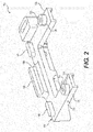
- Fig. 2 shows upright portion 110 and base portion 105 of bracket 100.
- First and second arms 120 and 130 of upright portion 110 may be configured to extend substantially perpendicularly from the base portion 105, may be substantially parallel to each other and may respectively include first and second fastener apertures 125 and 135.
- Apertures 125 and 135 may be configured to receive any suitable type of fastener, such as a bolt or screw, to create a non-permanent joint.
- Upright portion 110 may include one or more offset members, such as a first offset member 128 which extends substantially perpendicularly from first arm 128 and a second offset member 138 which extends substantially perpendicularly from second arm 138.
- First and second offset members 128 and 138 may be configured as spacers to surround the first and second receiving apertures 125 and 135, respectively.
- First and offset members 128 and 138 may be of substantially the same height and may have flat surfaces for mating with a major surface of a processor, to be described below.
- Base portion 105 may include a ledge 140 for receiving a first edge of a processor.
- Ledge 140 may be configured to extend substantially perpendicularly to upright portion 110 and may extend along a partial length of base portion 105.
- Ledge 140 may have various edge configurations, such as, for example, a tapered edge, square edge, or around edge, and may be centered along the length of base portion 105.
- ledge 140 may comprise more than one ledge portion, with multiple ledge portions being positioned symmetrically about the center of bracket 100.
- Base portion 105 may include a base offset member 148 which may extend substantially perpendicularly to upright portion 110.
- Base offset member 148 may be formed of a singular extension along the length of the bracket 100.
- base offset member 148 may be divided into portions positioned symmetrically about the center of bracket 100.
- Base offset member 148 may also be configured to extend adjacent to ledge portion 140.
- Base offset member 148 may be of a substantially equivalent height as first offset member 128 and second offset member 138.
- each of first offset member 128, second offset member 138 and base offset member 148 may be angled at an equivalent degree as each other offset member.
- Securement tab 150 may define a securement aperture 155 for securing a cable to the bracket. Securement tab 150 may extend from a peripheral surface of first arm 120. Securement tab 150 may assist with cable management by securing the cable to the securement tab 150. Cables may extend from one or more interface ports on a processor. The cable may be secured using a cable tie or electrical tape. Cable management may prevent cables associated with bracket 100 from becoming tangled with nearby cables.
- Base portion 105 may include a mounting aperture(s) 144.
- Mounting aperture(s) 144 may be configured to receive a fastener to mount bracket 100 and receive various types of fasteners such as a bolt or screw, to create a non-permanent joint.
- Mounting aperture(s) 144 may extend through base portion 105 substantially parallel to a locating pin 115. Locating pin 115 may extend from base portion 105, distal to ledge 140. Locating pin may also include a lead tapered featured to allow for smooth coupling with a receiving surface.
- a processor 210 in the form of a multi-component circuit board, may be mounted to bracket 100 and secured with a fastener 220.
- a first edge 218 of processor 210 may be in direct contact with ledge 140, such that ledge 140 may exert a normal force on first edge 218 to support processor 210.
- Processor 210 may include one or more known processing devices 240 such as, for example, microprocessors from the PentiumTM or XeonTM family manufactured by IntelTM, the TurionTM family manufactured by AMDTM, or any of various processors manufactured by Sun Microsystems.
- Processing devices 240 of processor 210 may comprise a single-core or multiple-core processors that execute parallel processes simultaneously.
- processor 210 may incorporate a single-core processor device configured with virtual processing technologies.
- processor 210 may use logical processor devices to simultaneously execute and control multiple processes.
- Processor 210 may implement virtual machine technologies, or other known technologies to provide the ability to execute, control, run, manipulate, store, etc. multiple software processes, applications, programs, etc. In another embodiment.
- Processor 210 may also include a single-board computer (SBC) comprising a microprocessor and memory built on a single circuit board.
- SBC single-board computer
- the SBC may further comprise ports for interfacing with various pins and connections such as USB 2.0, power input, SD card, or HDMI.
- Bracket 100 may be configured to secure an SBC including: Raspberry Pi 3, Raspberry Pi Zero, ODROID-XU4, Udoo x86 Ultra, CHIP, Orange Pi, HummingBoard-Gate.
- Other embodiments may be configured to receive SBCs manufactured by ORDOID, Asus, CanaKit, or PC.
- Processor 210 may also comprise one or more interface ports 230.
- Processor 210 may be mounted to bracket 100 such that base portion 105 does not inhibit the accessibility of interface ports 230.
- Interface ports 230 may be configured to receive any of a variety of inputs including: USB, MicroSD cards, DSI, power input, HDMI, CSI, composite video and audio output jack, LAN port, or GPIOs pins.
- a major surface 215 of processor 210 may be configured to mate with base offset member 148.
- Major surface 215 of processor 210 may bear against first offset member 128, second offset member 138, and base offset member 148.
- Fasteners 220 may be configured to be received through each of first and second fastener apertures 125 and 135.
- Base offset member may be configured to space major surface 215 of the processor 210 from bracket 100.
- Mounting structure 300 may include a spoke and hub configuration including a plurality of spokes 340 extending from a spindle 330 to a peripheral ring 350, thus forming a mounting surface 310 configured to bear against a bottom surface of brackets 100.
- Spindle 330 may extend substantially perpendicularly to mounting surface 310.
- Each spoke 340 may include mounting surface 310 for receiving a bracket-processor assembly 200.
- Apertures 360 between spokes 340 may provide for increased air ventilation and cooling through natural convection. Apertures 360 may also allow a user to access interfaces 230 that may be located on processor 210.
- Mounting structure 300 may include a peripheral ring 350 defining the outer perimeter of the mounting surface 310.
- Mounting surface 310 may include a plurality of receiving apertures 315 in spokes 340 each configured to comprise a geometric cross-section complementary to the cross-section of locating pins 115s to engage locating pins 115 of brackets 100.
- Mounting surface 310 may also include a plurality of mounting apertures 344 configured to align with mounting apertures 144 of brackets 100 when corresponding locating pins 115 are engaged with corresponding receiving apertures 315.
- Mounting surface 310 may be configured to receive a plurality of bracket-processor assemblies 200 such that processors 210 are mounted perpendicular to mounting surface 310. Bracket-processor assemblies 200 may be fastened to mounting surface 310 such that interface ports 230 are positioned over aperture 360.
- a stacked support assembly 500 comprising two support structures 300 for supporting a plurality of processors 210.
- a spindle 330 of a first mounting structure 300a may be configured to mate with a bottom surface of a second mounting structure 300b.
- a second circular array of bracket-processor assemblies 200b is stacked above a first circular array of bracket-processor assemblies 200a for a cluster application.
- stacked support assembly 500 is shown in Fig. 8 as including only two support structures 300a and 300b, other embodiments of stacked support assembly 500 may include a plurality of support structures 300a - 300n stacked to accommodate bracket-processor assemblies 200 for larger cluster applications.
Landscapes
- Engineering & Computer Science (AREA)
- Microelectronics & Electronic Packaging (AREA)
- General Engineering & Computer Science (AREA)
- Theoretical Computer Science (AREA)
- Computer Hardware Design (AREA)
- Physics & Mathematics (AREA)
- General Physics & Mathematics (AREA)
- Power Engineering (AREA)
- Human Computer Interaction (AREA)
- Thermal Sciences (AREA)
- Quality & Reliability (AREA)
- Cooling Or The Like Of Electrical Apparatus (AREA)
- Connection Of Plates (AREA)
Abstract
Description
- The present disclosure generally relates to an apparatus for mounting multiple processors for cluster computing.
- As technology has developed, the need for processing power has also increased. Cluster computing is a technique often employed to address this demand for increased processing power. In a computer cluster, multiple processors may be connected to each other to operate in parallel to perform coordinated operations. The connections may be made through hardware, networks, and/or software to cause the multiple processors in the cluster to function as a single system, working together to accomplish a programmed task. The multiple processors may be located in physical proximity to each other for ease of execution.
- In a cluster application, each computing unit is referred to as a "node." A node may be formed of a single processor or a processor set, to perform a particular task designated by a server. Cluster computing involves multiple servers coordinating tasks across multiple nodes. In doing so, cluster applications offer increased performance over the use of a single processor and are often employed in supercomputers for a wide range of computationally intensive tasks in the field of computational science.
- Types of computer cluster models include load-balancing clusters, high-availability clusters, and high-performance clusters. A load-balancing cluster model allocates the number of users or transactions of a particular system across a plurality of nodes. This increases the efficiency and processing time of a server. In a high-availability cluster model, multiple servers interact with a plurality of nodes such that certain servers replicate the operations of other servers to allow continued processing in the event of failure of a single node in the computer cluster. A high-performance cluster model provides parallel data processing for data-intensive computing. In all cluster computer models, advantages may include increased cost efficiency achieved from reduced power consumption and speed compared to use of mainframe computers, increased processing speed, improved network infrastructure, and flexibility for upgrades and adding additional components to the system.
- One of the obstacles associated with cluster applications is the limited availability of devices for mounting processors employed in cluster computing without impeding the above-mentioned advantages. Brackets are often used for mounting processors. However, difficulties are often encountered when using brackets for mounting processors for cluster applications, including excessive heat generation and limited access to interfaces on the processor.
- A large number of component failures in clusters are heat-related. Thus, there is a demand for a bracket and cluster mount configuration that reduces heat-related failures in order to increase the overall reliability of the cluster.
- Brackets currently available support individual processors horizontally. In such an arrangement, the major surface of the processor is generally parallel to a mounting surface, and in cluster configurations each processor is generally stacked on top of one another with limited space between each processor.
- This arrangement exacerbates the problem of overheating and minimizes the ability to effectively cool the processors without complex cooling arrangements (e.g., using high air-flow fans, heat sinks, and even liquid-cooling). One challenge associated with cooling through the use of a fan is that the nearby space to which the hot air is forced may be occupied by other processors or even other clusters of processors. Conversely, a cluster may receive hot air discharged by the cooling fan of a nearby cluster. This reduces the overall effectiveness of the cooling system which often does not realize a net reduction of heat surrounding the cluster. Therefore, a need exists for curing overheating-induced failures.
- While brackets exist for supporting processors, such brackets may exhibit difficulty in supporting processors having a plurality of ports for interfacing with related devices. For example, Raspberry Pi is a low-cost, widely-used, single-board computer configured to accept a plurality of inputs including USB, MicroSD cards, Display Serial Interface, micro USB Power input, HDMI, Camera Serial Interface port, composite video and audio output jack, LAN port, GPIOs pins, etc. Existing brackets mount processors in pairs to a single bracket, often shielding an edge of the processor, which makes it difficult to access ports located on the processor and interface other hardware with the processor.
- Existing brackets combined with the stacked cluster configuration described above limit user accessibility to an individual processor and also exacerbate the issue of the heat-induced failures. For example, a user may need to troubleshoot or replace a failed individual processor within the cluster. However, this may be difficult or impossible to do without disrupting the whole cluster, because the target processor may be supported in a dense field of other processors or may be secured to a bracket that is securing another processor. If the failed processor is not replaced, other processors in the cluster may experience a greater load and may generate more heat, leading to more system failures.
- Therefore, a need exists for a bracket capable of reducing the number of heat-induced failures within a cluster, while facilitating cluster configurations in which the arrangement of individual processors does not impede a user's ability to easily access a targeted processor. The present disclosure is directed to addressing these and other challenges.
- In the following description, certain aspects and embodiments of the present disclosure will become evident. It should be understood that the disclosure, in its broadest sense, could be practiced without having one or more features of these aspects and embodiments. Specifically, it should also be understood that these aspects and embodiments are merely exemplary. Moreover, although disclosed embodiments are discussed in the context of a processor bracket and, it is to be understood that the disclosed embodiments are not limited to any particular industry.
- According to an aspect of the present disclosure, there is provided a bracket for supporting a processor, the bracket comprising: a base portion configured to receive a first edge of the processor; an upright portion (may also be referred to as a support portion) configured to support to a major surface of the processor, the upright portion comprising a first arm and a second arm, the first arm being substantially parallel to the second arm; and a locating pin extending from the base portion in a direction distal to the first arm and second arm.
- The upright portion may be substantially perpendicular to the base portion.
- The base portion may comprise a ledge extending substantially perpendicular to the upright portion.
- The bracket may further comprise: a first offset member extending from the first arm; a second offset member extending from the second arm; and a base offset member extending from the base portion, wherein the first offset member, the second offset member, and the base offset member may be configured to bear against the major surface of the processor.
- The first offset member may be configured to extend substantially perpendicular to the first arm; and the second offset member may be configured to extend substantially perpendicular to the second arm.
- The base offset member may be configured to extend substantially perpendicular from the base portion.
- The first arm may comprise a first aperture configured to receive a first fastener for securing the processor to the first arm, and the second arm may comprise a second aperture configured to receive a second fastener for securing the processor to the second arm.
- The base portion may further comprises a third aperture.
- The third aperture may extend through the base portion substantially parallel to the locating pin, the third aperture being configured to receive a third fastener for securing the base portion to a surface.
- The bracket may further comprise a securement tab forming a fourth aperture for securing a cable to the bracket.
- The securement tab may extend from a peripheral surface of a proximal end of the first arm.
- The upright portion may comprise a rib extending substantially along a length of the base portion.
- The bracket may further comprise: a first gusset configured to support the first arm at an angle relative to the base portion; and a second gusset configured to support the second arm at an angle relative to the base portion.
- The bracket may further comprise a plurality of locating pins having circular cross sections of a diameter sized to be received within a plurality of apertures of a mounting structure for supporting an array of bracket-processor assemblies.
- The bracket may comprise a three-dimensionally printed layered acrylic material.
- Disclosed embodiments include a bracket for supporting a processor comprising a base portion configured to receive a first edge of the processor. The bracket may also include an upright portion comprising a first arm and a second arm, the first arm being substantially parallel to the second arm. The bracket may still further comprise a locating pin extending from the base portion in a direction distal to the first arm and second arm.
- Consistent with another disclosed embodiment, a bracket for supporting a processor comprises a base portion configured to receive a first edge of the processor. The base portion may comprise a first aperture configured to receive a fastener to mount the base portion to a surface. The bracket may also comprise an upright portion configured to support a major surface of the processor. The upright portion may comprise a first arm and a second arm. The first arm may be substantially parallel to the second arm and extend substantially perpendicular from the base portion. The bracket may still further comprise a first gusset configured to support the first arm at an angle relative to the base portion and a second gusset configured to support the second arm at an angle relative to the base portion.
- It is to be understood that both the foregoing general description and the following detailed description are exemplary and explanatory only, and are not restrictive of the disclosed embodiments, as claimed.
- The accompanying drawings, which are incorporated in and constitute a part of this specification, illustrate several embodiments and, together with the description, serve to explain the disclosed principles. In the drawings:
-
Fig. 1 is an isometric view of an exemplary processor bracket, showing a non-mounting side of the bracket, consistent with disclosed embodiments. -
Fig. 2 is an isometric view of an exemplary bracket, showing a top surface of the bracket, consistent with disclosed embodiments. -
Fig. 3 is an isometric view of an exemplary bracket, showing a bottom surface of the bracket, consistent with disclosed embodiments. -
Fig. 4 is an isometric view of an exemplary bracket, showing a processor mounted to the bracket. -
Fig. 5 is a right-side view of an exemplary bracket with a processor mounted to the bracket. -
Fig. 6 is an exploded view of an apparatus for supporting a cluster of processor-bracket assemblies aligned for mounting to an exemplary mounting surface, consistent with disclosed embodiments. -
Fig. 7 is an assembled view of the apparatus ofFig. 6 . -
Fig. 8 is an illustration of a stacked apparatus for supporting a cluster of brackets, consistent with disclosed embodiments. - Reference will now be made in detail to exemplary embodiments, examples of which are illustrated in the accompanying drawings and disclosed herein. Wherever convenient, the same reference numbers will be used throughout the drawings to refer to the same or like parts.
- The disclosed embodiments are directed to a bracket and to a stacked structure for supporting brackets in cluster applications.
- In a cluster, multiple processors operate in parallel to achieve increased processing power. A mounting system must be employed such that processors in the cluster are physically secured to ensure mechanical stability of a system but in such a way to allow access to the processors and their interfaces to facilitate maintenance of the system. Moreover, the mounting system must dissipate heat that is generated from the processors during their operation thereof while providing minimal interference to the system as a whole.
- The following description provides examples of systems for securing a processor to a bracket and an apparatus for mounting a processor for cluster computing. The arrangement of components shown in the Figures is not intended to limit the disclosed embodiments, as the components used in the disclosed bracket may vary.
-
Fig. 1 shows abracket 100.Bracket 100 may be formed of a layered acrylic material, for example, by a rapid prototyping process. The rapid prototyping method of manufacturing may include one or more of additive manufacturing processes, solid freeform fabrication processes, and computer numerically controlled (CNC) processes. A number of different additive manufacturing processes have been developed that can be used in accordance with various implementations of this disclosure to rapidly produce a prototype or model of the desired bracket from a three -dimensional (3D) data file defining the structure of the bracket. - In accordance with the disclosed embodiment,
bracket 100 may include abase portion 105 and anupright portion 110.Upright portion 110 may extend perpendicularly frombase portion 105 and may include afirst arm 120 and asecond arm 130.Upright portion 110 may be supported relative to thebase portion 105, in part by afirst gusset member 122 and asecond gusset member 132. First andsecond gusset members 122 and 133 may be substantially triangular in shape and may provide reinforced support at the section ofbracket 100 whereupright portion 110 intersectsbase portion 105. In particular, first andsecond gusset members upright portion 110, and may extend along a portion of the length ofupright portion 110. First andsecond gusset members bracket 100 by reinforcing the intersection ofupright portion 110 andbase portion 105, preventing high stress concentrations caused by bending moments that would otherwise develop at the intersection. -
Bracket 100 may also include arib 160 whereupright portion 110 intersectsbase portion 105.Rib 160 may extend along the length ofbase portion 105 ofbracket 100 and may be configured to extend substantially perpendicularly toupright portion 110.Rib 160 may add strength and stability to minimize deflection ofbracket 100. Increasing strength and stability ofbracket 100 may further improve the mechanical reliability of a processor mounted tobracket 100. -
Fig. 2 showsupright portion 110 andbase portion 105 ofbracket 100. First andsecond arms upright portion 110 may be configured to extend substantially perpendicularly from thebase portion 105, may be substantially parallel to each other and may respectively include first andsecond fastener apertures Apertures -
Upright portion 110 may include one or more offset members, such as a first offsetmember 128 which extends substantially perpendicularly fromfirst arm 128 and a second offsetmember 138 which extends substantially perpendicularly fromsecond arm 138. First and second offsetmembers apertures members -
Base portion 105 may include aledge 140 for receiving a first edge of a processor.Ledge 140 may be configured to extend substantially perpendicularly toupright portion 110 and may extend along a partial length ofbase portion 105.Ledge 140 may have various edge configurations, such as, for example, a tapered edge, square edge, or around edge, and may be centered along the length ofbase portion 105. In another embodiment,ledge 140 may comprise more than one ledge portion, with multiple ledge portions being positioned symmetrically about the center ofbracket 100. -
Base portion 105 may include a base offsetmember 148 which may extend substantially perpendicularly toupright portion 110. Base offsetmember 148 may be formed of a singular extension along the length of thebracket 100. In another embodiment, base offsetmember 148 may be divided into portions positioned symmetrically about the center ofbracket 100. Base offsetmember 148 may also be configured to extend adjacent toledge portion 140. Base offsetmember 148 may be of a substantially equivalent height as first offsetmember 128 and second offsetmember 138. In another embodiment, each of first offsetmember 128, second offsetmember 138 and base offsetmember 148 may be angled at an equivalent degree as each other offset member. - Referring now to
Fig. 3 , there is shown asecurement tab 150.Securement tab 150 may define asecurement aperture 155 for securing a cable to the bracket.Securement tab 150 may extend from a peripheral surface offirst arm 120.Securement tab 150 may assist with cable management by securing the cable to thesecurement tab 150. Cables may extend from one or more interface ports on a processor. The cable may be secured using a cable tie or electrical tape. Cable management may prevent cables associated withbracket 100 from becoming tangled with nearby cables. -
Base portion 105 may include a mounting aperture(s) 144. Mounting aperture(s) 144 may be configured to receive a fastener to mountbracket 100 and receive various types of fasteners such as a bolt or screw, to create a non-permanent joint. Mounting aperture(s) 144 may extend throughbase portion 105 substantially parallel to a locatingpin 115. Locatingpin 115 may extend frombase portion 105, distal toledge 140. Locating pin may also include a lead tapered featured to allow for smooth coupling with a receiving surface. - Referring now to
Fig. 4 , there is shown a bracket-processor assembly 200. Aprocessor 210, in the form of a multi-component circuit board, may be mounted tobracket 100 and secured with afastener 220. Afirst edge 218 ofprocessor 210 may be in direct contact withledge 140, such thatledge 140 may exert a normal force onfirst edge 218 to supportprocessor 210. -
Processor 210 may include one or moreknown processing devices 240 such as, for example, microprocessors from the Pentium™ or Xeon™ family manufactured by Intel™, the Turion™ family manufactured by AMD™, or any of various processors manufactured by Sun Microsystems.Processing devices 240 ofprocessor 210 may comprise a single-core or multiple-core processors that execute parallel processes simultaneously. For example,processor 210 may incorporate a single-core processor device configured with virtual processing technologies. In certain embodiments,processor 210 may use logical processor devices to simultaneously execute and control multiple processes.Processor 210 may implement virtual machine technologies, or other known technologies to provide the ability to execute, control, run, manipulate, store, etc. multiple software processes, applications, programs, etc. In another embodiment.Processor 210 may also include a single-board computer (SBC) comprising a microprocessor and memory built on a single circuit board. The SBC may further comprise ports for interfacing with various pins and connections such as USB 2.0, power input, SD card, or HDMI.Bracket 100 may be configured to secure an SBC including: Raspberry Pi 3, Raspberry Pi Zero, ODROID-XU4, Udoo x86 Ultra, CHIP, Orange Pi, HummingBoard-Gate. Other embodiments may be configured to receive SBCs manufactured by ORDOID, Asus, CanaKit, or Arduino. -
Processor 210 may also comprise one ormore interface ports 230.Processor 210 may be mounted tobracket 100 such thatbase portion 105 does not inhibit the accessibility ofinterface ports 230.Interface ports 230 may be configured to receive any of a variety of inputs including: USB, MicroSD cards, DSI, power input, HDMI, CSI, composite video and audio output jack, LAN port, or GPIOs pins. - Referring now to
Fig. 5 , there is shown a side view ofbracket processor assembly 200. Amajor surface 215 ofprocessor 210 may be configured to mate with base offsetmember 148.Major surface 215 ofprocessor 210 may bear against first offsetmember 128, second offsetmember 138, and base offsetmember 148.Fasteners 220 may be configured to be received through each of first andsecond fastener apertures major surface 215 of theprocessor 210 frombracket 100. - Referring now to
Fig. 6 , there is shown an exploded perspective view of a mountingstructure 300 for supporting an array of bracket-processor assemblies 200 in acluster assembly 400. Mountingstructure 300 may include a spoke and hub configuration including a plurality ofspokes 340 extending from aspindle 330 to aperipheral ring 350, thus forming a mountingsurface 310 configured to bear against a bottom surface ofbrackets 100.Spindle 330 may extend substantially perpendicularly to mountingsurface 310. Each spoke 340 may include mountingsurface 310 for receiving a bracket-processor assembly 200.Apertures 360 betweenspokes 340 may provide for increased air ventilation and cooling through natural convection.Apertures 360 may also allow a user to accessinterfaces 230 that may be located onprocessor 210. - Mounting
structure 300 may include aperipheral ring 350 defining the outer perimeter of the mountingsurface 310. Mountingsurface 310 may include a plurality of receivingapertures 315 inspokes 340 each configured to comprise a geometric cross-section complementary to the cross-section of locating pins 115s to engage locatingpins 115 ofbrackets 100. Mountingsurface 310 may also include a plurality of mountingapertures 344 configured to align with mountingapertures 144 ofbrackets 100 when corresponding locatingpins 115 are engaged with corresponding receivingapertures 315. - Referring now to
Fig. 7 , there is shown is a perspective view of an assembled mountingstructure 300. Mountingsurface 310 may be configured to receive a plurality of bracket-processor assemblies 200 such thatprocessors 210 are mounted perpendicular to mountingsurface 310. Bracket-processor assemblies 200 may be fastened to mountingsurface 310 such thatinterface ports 230 are positioned overaperture 360. - Referring now to
Fig. 8 , there is shown a stackedsupport assembly 500 comprising twosupport structures 300 for supporting a plurality ofprocessors 210. Aspindle 330 of afirst mounting structure 300a may be configured to mate with a bottom surface of asecond mounting structure 300b. In this arrangement, a second circular array of bracket-processor assemblies 200b is stacked above a first circular array of bracket-processor assemblies 200a for a cluster application. Althoughstacked support assembly 500 is shown inFig. 8 as including only twosupport structures stacked support assembly 500 may include a plurality ofsupport structures 300a - 300n stacked to accommodate bracket-processor assemblies 200 for larger cluster applications. - While illustrative embodiments have been described herein, the scope thereof includes any and all embodiments having equivalent elements, modifications, omissions, combinations (e.g., of aspects across various embodiments), adaptations and/or alterations as would be appreciated by those in the art based on the present disclosure. For example, the number and orientation of components shown in the exemplary systems may be modified. Thus, the foregoing description has been presented for purposes of illustration only. It is not exhaustive and is not limiting to the precise forms or embodiments disclosed. Modifications and adaptations will be apparent to those skilled in the art from consideration of the specification and practice of the disclosed embodiments.
- The elements in the claims are to be interpreted broadly based on the language employed in the claims and not limited to examples described in the present specification or during the prosecution of the application, which examples are to be construed as non-exclusive. It is intended, therefore, that the specification and examples be considered as exemplary only, with a true scope being indicated by the appended claims.
- Also described herein are the following numbered aspects:
- 1. A support structure for mounting an array of brackets, comprising:
- a first plate configured to receive the array of brackets;
- a spindle extending substantially perpendicular to the first plate, wherein the first plate comprises a plurality of radial segments extending from the spindle to a peripheral ring of an outer perimeter of the first plate; and
- a first aperture extending from the spindle to the peripheral ring of the outer perimeter, the first aperture separating a first one of the plurality of radial segments and a second one of the plurality of radial segments.
- 2. The support structure of aspect 1, wherein the first plate is substantially circular.
- 3. The support structure of aspect 2, wherein the first plate further comprises an inner perimeter configured to engage the spindle.
- 4. The support structure of any of aspects 1 to 3, wherein the first one of the plurality of radial segments is of substantially a same width as a base portion of a first bracket of the array of brackets.
- 5. The support structure of any of aspects 1 to 4, further comprising a second aperture configured to receive a locating pin of a first bracket of the array of brackets.
- 6. The support structure of aspect 5, further comprising a third aperture configured to receive a fastener.
- 7. The support structure of aspect 6, wherein the second aperture and the third aperture extend substantially parallel to the spindle and at least partially through the first one of the plurality of radial segments.
- 8. The support structure of any of aspects 5 to 7, wherein the second aperture comprises a cross section sized to engage the locating pin.
- 9. The support structure of any of aspects 1 to 8, further comprising a plurality of apertures, in addition to the first aperture, separating respective ones of the plurality of radial segments.
- 10. The support structure of aspect 9, wherein the array of brackets comprises eight brackets.
- 11. The support structure of any of aspects 1 to 10, wherein the first plate or the spindle or both comprises a layered acrylic material formed from a three-dimensional printing process.
- 12. The support structure of any of aspects 1 to 11, wherein the plurality of radial segments is arranged substantially symmetrically about the first plate.
- 13. The support structure of any of aspects 1 to 12, further comprising a second plate configured to receive a second array of brackets.
- 14. The support structure of aspect 13, wherein the second plate comprises an inner perimeter configured to engage the spindle.
- 15. The support structure of aspect 13 or aspect 14, wherein the second plate is substantially parallel to the first plate.
- 16. The support structure of any aspect 13 to 15, wherein the second array of brackets comprises eight brackets.
- 17. The support structure of any of aspects 13 to 16, wherein the spindle comprises a proximal portion configured to engage with the first plate and a distal portion configured to engage with the second plate.
- 18. The support structure of any of aspects 13 to 17, wherein the second plate comprises a layered acrylic material formed from a three-dimensional printing process.
- 19. The support structure of any of aspects 13 to 18, wherein the second plate comprises a plurality of radial segments extending from the spindle to an outer perimeter of the second plate.
- 20. The support structure of any of aspects 1 to 19, wherein the spindle comprises layered acrylic material formed from a three-dimensional printing process.
- 21. A bracket for supporting a processor, comprising:
- a base portion configured to receive a first edge of the processor;
- an upright portion configured to support to a major surface of the processor, the upright portion comprising a first arm and a second arm, the first arm being substantially parallel to a second arm; and
- a locating pin extending from the base portion in a direction distal to the first arm and second arm.
- 22. The bracket of aspect 22, wherein the upright portion is substantially perpendicular to the base portion.
- 23. The bracket of aspect 21 or aspect 22, wherein the base portion comprises a ledge extending substantially perpendicular to the first arm and the second arm.
- 24. The bracket of any of aspects 21 to 23, further comprising:
- a first offset member extending from the first arm;
- a second offset member extending from the second arm; and
- a base offset member extending from the base portion, wherein the first offset member, the second offset member, and the base offset member are configured to bear against the major surface of the processor.
- 25. The bracket of any of aspects 21 to 24, wherein:
- the first arm comprises a first aperture configured to receive a first fastener for securing the processor to the first arm, and
- the second arm comprises a second aperture configured to receive a second fastener for securing the processor to the second arm.
- 26. The bracket of any of aspects 21 to 25, wherein the base portion further comprises a third aperture.
- 27. The bracket of aspect 26, wherein the third aperture extends through the base portion substantially parallel to the locating pin, the third aperture being configured to receive a third fastener for securing the base portion to a surface.
- 28. The bracket of any of aspects 21 to 27, further comprising a plurality of locating pins having circular cross sections of a diameter sized to be received within the first and second apertures.
- 29. The bracket of any of aspects 21 to 28, further comprising a securement tab forming a fourth aperture for securing a cable to the bracket.
- 30. The bracket of aspect 29, wherein the securement tab extends from a peripheral surface of a proximal end of the first arm.
- 31. The bracket of any of aspects 21 to 30, wherein the upright portion comprises a rib extending substantially along a length of the base portion.
- 32. The bracket of any of any of aspects 21 to 31, further comprising a plurality of locating pins having circular cross sections of a diameter sized to be received within a plurality of apertures of a mounting structure for supporting an array of bracket-processor assemblies.
- 33. The bracket of any of aspects 21 to 32, wherein the bracket comprises a three-dimensionally printed layered acrylic material.
- 34. A bracket for supporting a processor, comprising:
- a base portion configured to receive a first edge of the processor, the base portion comprising a first aperture, the first aperture being configured to receive a fastener to mount the base portion to a surface;
- an upright portion configured to support a major surface of the processor, the upright portion comprising a first arm and a second arm, the first arm being substantially parallel to the second arm and extending substantially perpendicularly from the base portion;
- a first gusset configured to support the first arm at an angle relative to the base portion;
- a second gusset configured to support the second arm at an angle relative to the base portion;
- a locating pin extending distal to the first arm and the second arm, the locating pin being configured to couple the base portion to the surface; and
- a securement tab forming a second aperture configured to secure a cable to the bracket.
- 35. The bracket of aspect 34, wherein the base portion comprises a ledge extending substantially perpendicular to the upright portion.
- 36. The bracket of aspect 35, wherein:
- the first arm comprises a third aperture configured to receive a fastener securing the processor to the first arm, and
- the second arm comprises a fourth aperture configured to receive a fastener securing the processor to the second arm.
- 37. The bracket of any of aspects 34 to 36, wherein:
- the first arm comprises a first offset member configured to bear against the major surface of the processor and extend substantially perpendicular to the first arm; and
- the second arm comprises a second offset member configured to bear against the major surface of the processor and extend substantially perpendicular to the second arm.
- 38. The bracket of aspect 37, further comprising a base offset member configured to bear against the major surface of the processor and extend substantially perpendicular from the base portion.
- 39. The bracket of any of aspects 34 to 38, wherein the locating pin comprises a diameter sized to be received within a fifth aperture of the surface.
- 40. The bracket of any of aspects 34 to 38, wherein the securement tab extends from a peripheral surface of a proximal end of the first arm.
- 41. The bracket of any of aspects 34 to 40, wherein the bracket comprises a three-dimensionally printed layered acrylic material.
- 42. A stacked support structure for supporting a plurality of brackets, the stacked support structure comprising:
- a first plate configured to receive a first array of brackets;
- a second plate, substantially parallel to the first plate, configured to receive a second array of brackets; and
- a spindle comprising a proximal portion configure to engage the first plate and a distal portion configured to engage the second plate.
- 43. The stacked support structure of aspect 42, wherein the first array of brackets and/or second array of bracket comprises a plurality of brackets, each bracket as defined by any of aspects 34 to 41.
- 44. The stacked support structure of aspect 42 or aspect 43, wherein the stacked support structure comprises a layered acrylic three-dimensionally printed material.
- 45. The stacked support structure of any of aspects 42 to 44, wherein the first plate and the second plate comprise a plurality of radial segments about the spindle.
- 46. The stacked support structure of aspect 44, wherein the first plate and second plate comprise a first aperture between each radial segment.
- 46. The stacked support structure of aspect 45, wherein the first aperture of each of the first and second plate are configured to respectively extend through the first and second plate.
- 47. The stacked support structure of any of aspects 42 to 46, wherein the radial segments each comprise:
- a second aperture configured to engage a locating pin of the bracket; and
- a third aperture configured to receive a fastener.
- 48. The stacked support structure of aspect 47, wherein the second aperture and third aperture extend substantially parallel to the spindle at least partially through the radial segment.
- 49. The stacked support structure of aspect 48, comprising a plurality of the second apertures arranged substantially symmetrically about the spindle.
- 50. The stacked support structure of aspect 48 or aspect 49, comprising a plurality of the third apertures arranged substantially symmetrically about the spindle.
Claims (15)
- A bracket (100) for supporting a processor (210), the bracket comprising:a base portion (105) configured to receive a first edge of the processor;an upright portion (110) configured to support to a major surface of the processor, the upright portion comprising a first arm (120) and a second arm (130), the first arm being substantially parallel to the second arm; anda locating pin (115) extending from the base portion in a direction distal to the first arm and second arm.
- The bracket of claim 1, wherein the upright portion (110) is substantially perpendicular to the base portion (105).
- The bracket of claim 1 or claim 2, wherein the base portion (105) comprises a ledge (140) extending substantially perpendicular to the upright portion (110).
- The bracket of any of claims 1 to 3, further comprising:a first offset member (128) extending from the first arm (120);a second offset member (138) extending from the second arm (130); anda base offset member (148) extending from the base portion (105), wherein the first offset member (128), the second offset member (138), and the base offset member (148) are configured to bear against the major surface (215) of the processor.
- The bracket of claim 4, wherein:the first offset member (128) is configured to extend substantially perpendicular to the first arm; andthe second offset (138) member is configured to extend substantially perpendicular to the second arm.
- The bracket of claim 4 or 5, wherein the base offset member (148) is configured to extend substantially perpendicular from the base portion (105).
- The bracket of any of claims 1 to 6, wherein:the first arm (120) comprises a first aperture (125) configured to receive a first fastener (220) for securing the processor (210) to the first arm, andthe second arm (130) comprises a second aperture (135) configured to receive a second fastener (220) for securing the processor (210) to the second arm.
- The bracket of any of claims 1 to 7, wherein the base portion (105) further comprises a third aperture (144).
- The bracket of claim 8, wherein the third aperture (144) extends through the base portion (105) substantially parallel to the locating pin (115), the third aperture (144) being configured to receive a third fastener for securing the base portion (105) to a surface.
- The bracket of any of claims 1 to 9, further comprising a securement tab (150) forming a fourth aperture (155) for securing a cable to the bracket.
- The bracket of claim 10, wherein the securement tab (150) extends from a peripheral surface of a proximal end of the first arm.
- The bracket of any of claims 1 to 11, wherein the upright portion (110) comprises a rib (160) extending substantially along a length of the base portion (105).
- The bracket of any of claims 1 to 12, further comprising:a first gusset (122) configured to support the first arm (120) at an angle relative to the base portion (105); anda second gusset (132) configured to support the second arm (130) at an angle relative to the base portion (105).
- The bracket of any of claims 1 to 13, further comprising a plurality of locating pins (115) having circular cross sections of a diameter sized to be received within a plurality of apertures (315) of a mounting structure (300) for supporting an array of bracket-processor assemblies.
- The bracket of any of the preceding claims, wherein the bracket (100) comprises a three-dimensionally printed layered acrylic material.
Applications Claiming Priority (1)
| Application Number | Priority Date | Filing Date | Title |
|---|---|---|---|
| US15/848,369 US10499524B2 (en) | 2017-12-20 | 2017-12-20 | Apparatus for mounting a processor for cluster computing |
Publications (2)
| Publication Number | Publication Date |
|---|---|
| EP3502830A1 true EP3502830A1 (en) | 2019-06-26 |
| EP3502830B1 EP3502830B1 (en) | 2024-01-24 |
Family
ID=64746395
Family Applications (1)
| Application Number | Title | Priority Date | Filing Date |
|---|---|---|---|
| EP18214527.6A Active EP3502830B1 (en) | 2017-12-20 | 2018-12-20 | Apparatus for mounting processors for cluster computing |
Country Status (4)
| Country | Link |
|---|---|
| US (5) | US10499524B2 (en) |
| EP (1) | EP3502830B1 (en) |
| CN (1) | CN109947220A (en) |
| CA (1) | CA3027801A1 (en) |
Families Citing this family (14)
| Publication number | Priority date | Publication date | Assignee | Title |
|---|---|---|---|---|
| USD866551S1 (en) * | 2017-10-18 | 2019-11-12 | Ncomputing Co., Ltd. | Network computing terminal |
| JP6589028B1 (en) * | 2018-09-21 | 2019-10-09 | 有限会社アイ電気 | Electronic circuit holder |
| CN112243078A (en) * | 2020-10-15 | 2021-01-19 | 平顶山学院 | Extensible multi-path image acquisition device |
| US11825622B2 (en) * | 2020-11-12 | 2023-11-21 | Legrand DPC, LLC | Single-board computer cartridge |
| CN113163677B (en) * | 2021-03-25 | 2023-01-17 | 联想(北京)有限公司 | Electronic equipment |
| US12200886B2 (en) | 2022-10-20 | 2025-01-14 | Dell Products L.P. | System and method for thermal management of removable components |
| US12575020B2 (en) | 2022-10-20 | 2026-03-10 | Dell Products L.P. | System for thermal management of storage devices |
| US12200898B2 (en) | 2022-10-20 | 2025-01-14 | Dell Products L.P. | System and method for managing component positioning and orientation in data processing systems |
| US12133356B2 (en) | 2022-10-20 | 2024-10-29 | Dell Products L.P. | System and method for managing retaining cooling components in data processing systems |
| US12317446B2 (en) | 2022-10-20 | 2025-05-27 | Dell Products L.P. | System and method for improving rate of air flow through data processing systems |
| US12346174B2 (en) | 2022-10-21 | 2025-07-01 | Dell Products L.P. | System and method for management of data processing system components |
| US12597722B2 (en) | 2022-10-21 | 2026-04-07 | Dell Products L.P. | System and method for connection management in data processing system |
| US12174823B2 (en) | 2022-10-21 | 2024-12-24 | Dell Products L.P. | System and method to ensure data integrity of software defined storage system |
| US12101913B2 (en) | 2022-11-29 | 2024-09-24 | Dell Products L.P. | Variable topography heat sink fins |
Citations (3)
| Publication number | Priority date | Publication date | Assignee | Title |
|---|---|---|---|---|
| US5980275A (en) * | 1995-08-21 | 1999-11-09 | International Business Machines, Corp. | Electronic circuit board interface mounting bracket |
| EP0973098A1 (en) * | 1994-03-11 | 2000-01-19 | The Panda Project | High density connector system |
| US6168450B1 (en) * | 1998-01-29 | 2001-01-02 | The Whitaker Corporation | Slot 1 retention device for processor module |
Family Cites Families (43)
| Publication number | Priority date | Publication date | Assignee | Title |
|---|---|---|---|---|
| US3272933A (en) * | 1964-07-10 | 1966-09-13 | Sperry Rand Corp | Rotary indexing programmer switch using circuit boards |
| US3833840A (en) * | 1973-06-14 | 1974-09-03 | Bell Telephone Labor Inc | Cylindrically arranged modular main distribution frame |
| US4589712A (en) * | 1977-08-25 | 1986-05-20 | Hastings Otis | Data processing equipment enclosures |
| US4542442A (en) * | 1983-06-17 | 1985-09-17 | Simmonds Precision Products, Inc. | Apparatus for the mounting and wiring of printed circuit boards |
| US4850892A (en) * | 1985-12-16 | 1989-07-25 | Wang Laboratories, Inc. | Connecting apparatus for electrically connecting memory modules to a printed circuit board |
| US4679872A (en) * | 1986-01-27 | 1987-07-14 | Coe Larry D | Cylindrical back plane structure for receiving printed circuit boards |
| US4903603A (en) * | 1986-03-25 | 1990-02-27 | Hughes Aircraft Company | Stacked circuit cards and guided vehicle configurations |
| US4922381A (en) * | 1986-03-25 | 1990-05-01 | Hughes Aircraft Company | Stacked circuit cards and guided configurations |
| US4862075A (en) * | 1988-09-01 | 1989-08-29 | Photon Dynamics, Inc. | High frequency test head using electro-optics |
| US4917624A (en) * | 1989-03-28 | 1990-04-17 | Yu Mu Gen | Socket for printed circuit board |
| JP2591677B2 (en) * | 1989-04-21 | 1997-03-19 | 株式会社 グラフィコ | Radial parallel system bus |
| US5063475A (en) * | 1990-03-19 | 1991-11-05 | International Business Machines Corporation | Multileveled electronic assembly with cooling means |
| JP2700837B2 (en) * | 1990-10-19 | 1998-01-21 | 株式会社 グラフィコ | Board connection device for radiation type parallel system bus |
| US5150279A (en) * | 1991-03-18 | 1992-09-22 | International Business Machines Corporation | High performance computer system with platters and unidirectional storage modules therebetween |
| JPH04320509A (en) * | 1991-04-19 | 1992-11-11 | Gurafuiko:Kk | Parallel processor |
| US5289694A (en) * | 1993-02-26 | 1994-03-01 | At&T Bell Laboratories | Circuit card mounting assembly |
| US5889651A (en) * | 1995-05-31 | 1999-03-30 | Kabushiki Kaisha Toshiba | Circuit board cooling apparatus |
| US5621617A (en) * | 1995-06-07 | 1997-04-15 | Hughes Missile Systems Company | Circuit card mounting system having a cylindrical housing and circular card locks |
| US6280956B1 (en) | 1995-11-03 | 2001-08-28 | University Of Pittsburgh | Antibodies to bladder cancer nuclear matrix proteins and their use |
| US5726865A (en) * | 1996-06-18 | 1998-03-10 | Intel Corporation | Circuit board retention system |
| US5650917A (en) * | 1996-10-09 | 1997-07-22 | Hsu; Fu-Yu | CPU card mounting structure |
| US5903432A (en) * | 1997-09-19 | 1999-05-11 | Intel Corportation | Computer package with a polygonal shaped motherboard |
| US6078504A (en) * | 1997-10-08 | 2000-06-20 | Cisco Systems, Inc. | Universal adapter bracket for communications devices |
| US6155433A (en) | 1997-12-01 | 2000-12-05 | Intel Corporation | Dual processor retention module |
| US6381148B1 (en) | 1998-12-09 | 2002-04-30 | Intel, Corp. | Dual processor retention assembly |
| US6269001B1 (en) | 2000-04-20 | 2001-07-31 | International Business Machines Corporation | System for enhanced cooling and latching of pluggable electronic component |
| US6664673B2 (en) * | 2001-08-27 | 2003-12-16 | Advanced Rotary Systems Llc | Cooler for electronic devices |
| US6744637B2 (en) * | 2001-11-30 | 2004-06-01 | Alliant Techsystems Inc. | Guided munitions electronics package and method |
| US7390197B2 (en) * | 2002-07-17 | 2008-06-24 | Oqo Incorporated | Electronic device with integral connectors |
| CA2503791A1 (en) * | 2002-10-22 | 2004-05-06 | Jason A. Sullivan | Non-peripherals processing control module having improved heat dissipating properties |
| US7314341B2 (en) * | 2003-01-10 | 2008-01-01 | Liconic Ag | Automatic storage device and climate controlled cabinet with such a device |
| US7133289B2 (en) * | 2003-07-28 | 2006-11-07 | Derick Arippol | Housing assembly for stacking multiple computer modules |
| US6865085B1 (en) * | 2003-09-26 | 2005-03-08 | Adc Dsl Systems, Inc. | Heat dissipation for electronic enclosures |
| WO2009032144A2 (en) * | 2007-08-28 | 2009-03-12 | General Dynamics Advanced Information Systems, Inc. | System and method for interconnecting circuit boards |
| US8189345B2 (en) * | 2008-06-18 | 2012-05-29 | Lockheed Martin Corporation | Electronics module, enclosure assembly housing same, and related systems and methods |
| CN201229538Y (en) * | 2008-07-04 | 2009-04-29 | 鸿富锦精密工业(深圳)有限公司 | Computer machine box |
| GB2476501B (en) * | 2009-12-24 | 2012-07-18 | Richard John Edward Aras | Geodesic massively-parallel supercomputer |
| TWI488362B (en) * | 2012-03-08 | 2015-06-11 | Univ Nat Chiao Tung | A beam steering antenna structure |
| US8842432B2 (en) * | 2012-09-22 | 2014-09-23 | Facebook, Inc. | Arrangement of computing assets in a data center |
| US9395772B2 (en) * | 2013-06-07 | 2016-07-19 | Apple Inc. | Computer internal architecture |
| US10039211B2 (en) * | 2015-03-09 | 2018-07-31 | Vapor IO Inc. | Rack for computing equipment |
| EP3254540B1 (en) * | 2015-03-09 | 2020-12-02 | Vapor Io Inc. | Rack for computing equipment |
| US9985842B2 (en) * | 2015-10-30 | 2018-05-29 | Vapor IO Inc. | Bus bar power adapter for AC-input, hot-swap power supplies |
-
2017
- 2017-12-20 US US15/848,369 patent/US10499524B2/en active Active
- 2017-12-21 US US15/849,846 patent/US10292296B1/en active Active
-
2018
- 2018-12-17 CA CA3027801A patent/CA3027801A1/en active Pending
- 2018-12-20 CN CN201811590664.2A patent/CN109947220A/en active Pending
- 2018-12-20 EP EP18214527.6A patent/EP3502830B1/en active Active
-
2019
- 2019-01-28 US US16/259,061 patent/US10595432B2/en active Active
- 2019-03-29 US US16/369,212 patent/US10555434B2/en active Active
-
2020
- 2020-02-21 US US16/797,469 patent/US11129293B2/en active Active
Patent Citations (3)
| Publication number | Priority date | Publication date | Assignee | Title |
|---|---|---|---|---|
| EP0973098A1 (en) * | 1994-03-11 | 2000-01-19 | The Panda Project | High density connector system |
| US5980275A (en) * | 1995-08-21 | 1999-11-09 | International Business Machines, Corp. | Electronic circuit board interface mounting bracket |
| US6168450B1 (en) * | 1998-01-29 | 2001-01-02 | The Whitaker Corporation | Slot 1 retention device for processor module |
Also Published As
| Publication number | Publication date |
|---|---|
| US10499524B2 (en) | 2019-12-03 |
| US20200196477A1 (en) | 2020-06-18 |
| US20190230810A1 (en) | 2019-07-25 |
| US10555434B2 (en) | 2020-02-04 |
| EP3502830B1 (en) | 2024-01-24 |
| CA3027801A1 (en) | 2019-06-20 |
| US20190191584A1 (en) | 2019-06-20 |
| US20190191587A1 (en) | 2019-06-20 |
| CN109947220A (en) | 2019-06-28 |
| US11129293B2 (en) | 2021-09-21 |
| US10292296B1 (en) | 2019-05-14 |
| US10595432B2 (en) | 2020-03-17 |
Similar Documents
| Publication | Publication Date | Title |
|---|---|---|
| US11129293B2 (en) | Apparatus for mounting processors for cluster computing | |
| US11133239B2 (en) | Mechanical part for fastening processor, assembly, and computer device | |
| US6487080B2 (en) | Sub rack based vertical housing for computer systems | |
| US7821792B2 (en) | Cell board interconnection architecture | |
| JP3173340U (en) | Server system | |
| US9257818B2 (en) | Enclosure power distribution architectures | |
| US20030011976A1 (en) | Modular packaging configuration and system and method of use for a computer system adapted for operating multiple operating systems in different partitions | |
| US11150707B2 (en) | Graphic processing unit and host casing hardware configuration | |
| US7643286B2 (en) | Symmetric multiprocessing computer and star interconnection architecture and cooling system thereof | |
| US9491891B2 (en) | System and design of cost effective chassis design for networking products | |
| EP3716009B1 (en) | Chassis of server and server | |
| RU2635896C1 (en) | High-performance computer platform based on processors with heterogeneous architecture | |
| US9417671B2 (en) | Computer baffle | |
| EP3068204B1 (en) | Unit device | |
| CN112943703A (en) | Fan module and server comprising same | |
| US20070297158A1 (en) | Front-to-back stacked device | |
| CN108536239B (en) | Machine box | |
| CN217034655U (en) | Double-circuit server | |
| CN110764593A (en) | Server machine case and fan module damping mounting structure thereof | |
| US20250380374A1 (en) | Server | |
| CN113126704B (en) | Mainboard applied to computing equipment, computing equipment and data center machine room | |
| TWM613502U (en) | Computing device with reconfigurable front and rear access | |
| TW202512824A (en) | Assembly for hanging external modules | |
| CN116775539A (en) | Mainboard of double-path server and server | |
| US20220159869A1 (en) | Knockdown water-cooling unit latch device structure |
Legal Events
| Date | Code | Title | Description |
|---|---|---|---|
| PUAI | Public reference made under article 153(3) epc to a published international application that has entered the european phase |
Free format text: ORIGINAL CODE: 0009012 |
|
| STAA | Information on the status of an ep patent application or granted ep patent |
Free format text: STATUS: THE APPLICATION HAS BEEN PUBLISHED |
|
| AK | Designated contracting states |
Kind code of ref document: A1 Designated state(s): AL AT BE BG CH CY CZ DE DK EE ES FI FR GB GR HR HU IE IS IT LI LT LU LV MC MK MT NL NO PL PT RO RS SE SI SK SM TR |
|
| AX | Request for extension of the european patent |
Extension state: BA ME |
|
| STAA | Information on the status of an ep patent application or granted ep patent |
Free format text: STATUS: REQUEST FOR EXAMINATION WAS MADE |
|
| 17P | Request for examination filed |
Effective date: 20191230 |
|
| RBV | Designated contracting states (corrected) |
Designated state(s): AL AT BE BG CH CY CZ DE DK EE ES FI FR GB GR HR HU IE IS IT LI LT LU LV MC MK MT NL NO PL PT RO RS SE SI SK SM TR |
|
| STAA | Information on the status of an ep patent application or granted ep patent |
Free format text: STATUS: EXAMINATION IS IN PROGRESS |
|
| 17Q | First examination report despatched |
Effective date: 20210722 |
|
| REG | Reference to a national code |
Ref country code: DE Free format text: PREVIOUS MAIN CLASS: G06F0001180000 Ref country code: DE Ref legal event code: R079 Ref document number: 602018064439 Country of ref document: DE Free format text: PREVIOUS MAIN CLASS: G06F0001180000 Ipc: H05K0007140000 |
|
| RIC1 | Information provided on ipc code assigned before grant |
Ipc: G06F 1/18 20060101ALI20230621BHEP Ipc: H05K 7/14 20060101AFI20230621BHEP |
|
| GRAP | Despatch of communication of intention to grant a patent |
Free format text: ORIGINAL CODE: EPIDOSNIGR1 |
|
| STAA | Information on the status of an ep patent application or granted ep patent |
Free format text: STATUS: GRANT OF PATENT IS INTENDED |
|
| INTG | Intention to grant announced |
Effective date: 20230728 |
|
| GRAS | Grant fee paid |
Free format text: ORIGINAL CODE: EPIDOSNIGR3 |
|
| GRAA | (expected) grant |
Free format text: ORIGINAL CODE: 0009210 |
|
| STAA | Information on the status of an ep patent application or granted ep patent |
Free format text: STATUS: THE PATENT HAS BEEN GRANTED |
|
| P01 | Opt-out of the competence of the unified patent court (upc) registered |
Effective date: 20231201 |
|
| AK | Designated contracting states |
Kind code of ref document: B1 Designated state(s): AL AT BE BG CH CY CZ DE DK EE ES FI FR GB GR HR HU IE IS IT LI LT LU LV MC MK MT NL NO PL PT RO RS SE SI SK SM TR |
|
| REG | Reference to a national code |
Ref country code: GB Ref legal event code: FG4D |
|
| REG | Reference to a national code |
Ref country code: CH Ref legal event code: EP |
|
| REG | Reference to a national code |
Ref country code: IE Ref legal event code: FG4D |
|
| REG | Reference to a national code |
Ref country code: DE Ref legal event code: R096 Ref document number: 602018064439 Country of ref document: DE |
|
| REG | Reference to a national code |
Ref country code: LT Ref legal event code: MG9D |
|
| REG | Reference to a national code |
Ref country code: NL Ref legal event code: MP Effective date: 20240124 |
|
| PG25 | Lapsed in a contracting state [announced via postgrant information from national office to epo] |
Ref country code: NL Free format text: LAPSE BECAUSE OF FAILURE TO SUBMIT A TRANSLATION OF THE DESCRIPTION OR TO PAY THE FEE WITHIN THE PRESCRIBED TIME-LIMIT Effective date: 20240124 |
|
| PG25 | Lapsed in a contracting state [announced via postgrant information from national office to epo] |
Ref country code: NL Free format text: LAPSE BECAUSE OF FAILURE TO SUBMIT A TRANSLATION OF THE DESCRIPTION OR TO PAY THE FEE WITHIN THE PRESCRIBED TIME-LIMIT Effective date: 20240124 |
|
| PG25 | Lapsed in a contracting state [announced via postgrant information from national office to epo] |
Ref country code: IS Free format text: LAPSE BECAUSE OF FAILURE TO SUBMIT A TRANSLATION OF THE DESCRIPTION OR TO PAY THE FEE WITHIN THE PRESCRIBED TIME-LIMIT Effective date: 20240524 |
|
| PG25 | Lapsed in a contracting state [announced via postgrant information from national office to epo] |
Ref country code: LT Free format text: LAPSE BECAUSE OF FAILURE TO SUBMIT A TRANSLATION OF THE DESCRIPTION OR TO PAY THE FEE WITHIN THE PRESCRIBED TIME-LIMIT Effective date: 20240124 |
|
| PG25 | Lapsed in a contracting state [announced via postgrant information from national office to epo] |
Ref country code: GR Free format text: LAPSE BECAUSE OF FAILURE TO SUBMIT A TRANSLATION OF THE DESCRIPTION OR TO PAY THE FEE WITHIN THE PRESCRIBED TIME-LIMIT Effective date: 20240425 |
|
| REG | Reference to a national code |
Ref country code: AT Ref legal event code: MK05 Ref document number: 1653170 Country of ref document: AT Kind code of ref document: T Effective date: 20240124 |
|
| PG25 | Lapsed in a contracting state [announced via postgrant information from national office to epo] |
Ref country code: HR Free format text: LAPSE BECAUSE OF FAILURE TO SUBMIT A TRANSLATION OF THE DESCRIPTION OR TO PAY THE FEE WITHIN THE PRESCRIBED TIME-LIMIT Effective date: 20240124 Ref country code: RS Free format text: LAPSE BECAUSE OF FAILURE TO SUBMIT A TRANSLATION OF THE DESCRIPTION OR TO PAY THE FEE WITHIN THE PRESCRIBED TIME-LIMIT Effective date: 20240424 |
|
| PG25 | Lapsed in a contracting state [announced via postgrant information from national office to epo] |
Ref country code: ES Free format text: LAPSE BECAUSE OF FAILURE TO SUBMIT A TRANSLATION OF THE DESCRIPTION OR TO PAY THE FEE WITHIN THE PRESCRIBED TIME-LIMIT Effective date: 20240124 |
|
| PG25 | Lapsed in a contracting state [announced via postgrant information from national office to epo] |
Ref country code: AT Free format text: LAPSE BECAUSE OF FAILURE TO SUBMIT A TRANSLATION OF THE DESCRIPTION OR TO PAY THE FEE WITHIN THE PRESCRIBED TIME-LIMIT Effective date: 20240124 |
|
| PG25 | Lapsed in a contracting state [announced via postgrant information from national office to epo] |
Ref country code: RS Free format text: LAPSE BECAUSE OF FAILURE TO SUBMIT A TRANSLATION OF THE DESCRIPTION OR TO PAY THE FEE WITHIN THE PRESCRIBED TIME-LIMIT Effective date: 20240424 Ref country code: NO Free format text: LAPSE BECAUSE OF FAILURE TO SUBMIT A TRANSLATION OF THE DESCRIPTION OR TO PAY THE FEE WITHIN THE PRESCRIBED TIME-LIMIT Effective date: 20240424 Ref country code: LT Free format text: LAPSE BECAUSE OF FAILURE TO SUBMIT A TRANSLATION OF THE DESCRIPTION OR TO PAY THE FEE WITHIN THE PRESCRIBED TIME-LIMIT Effective date: 20240124 Ref country code: IS Free format text: LAPSE BECAUSE OF FAILURE TO SUBMIT A TRANSLATION OF THE DESCRIPTION OR TO PAY THE FEE WITHIN THE PRESCRIBED TIME-LIMIT Effective date: 20240524 Ref country code: HR Free format text: LAPSE BECAUSE OF FAILURE TO SUBMIT A TRANSLATION OF THE DESCRIPTION OR TO PAY THE FEE WITHIN THE PRESCRIBED TIME-LIMIT Effective date: 20240124 Ref country code: GR Free format text: LAPSE BECAUSE OF FAILURE TO SUBMIT A TRANSLATION OF THE DESCRIPTION OR TO PAY THE FEE WITHIN THE PRESCRIBED TIME-LIMIT Effective date: 20240425 Ref country code: FI Free format text: LAPSE BECAUSE OF FAILURE TO SUBMIT A TRANSLATION OF THE DESCRIPTION OR TO PAY THE FEE WITHIN THE PRESCRIBED TIME-LIMIT Effective date: 20240124 Ref country code: ES Free format text: LAPSE BECAUSE OF FAILURE TO SUBMIT A TRANSLATION OF THE DESCRIPTION OR TO PAY THE FEE WITHIN THE PRESCRIBED TIME-LIMIT Effective date: 20240124 Ref country code: BG Free format text: LAPSE BECAUSE OF FAILURE TO SUBMIT A TRANSLATION OF THE DESCRIPTION OR TO PAY THE FEE WITHIN THE PRESCRIBED TIME-LIMIT Effective date: 20240124 Ref country code: AT Free format text: LAPSE BECAUSE OF FAILURE TO SUBMIT A TRANSLATION OF THE DESCRIPTION OR TO PAY THE FEE WITHIN THE PRESCRIBED TIME-LIMIT Effective date: 20240124 |
|
| PG25 | Lapsed in a contracting state [announced via postgrant information from national office to epo] |
Ref country code: PT Free format text: LAPSE BECAUSE OF FAILURE TO SUBMIT A TRANSLATION OF THE DESCRIPTION OR TO PAY THE FEE WITHIN THE PRESCRIBED TIME-LIMIT Effective date: 20240524 Ref country code: PL Free format text: LAPSE BECAUSE OF FAILURE TO SUBMIT A TRANSLATION OF THE DESCRIPTION OR TO PAY THE FEE WITHIN THE PRESCRIBED TIME-LIMIT Effective date: 20240124 |
|
| PG25 | Lapsed in a contracting state [announced via postgrant information from national office to epo] |
Ref country code: SE Free format text: LAPSE BECAUSE OF FAILURE TO SUBMIT A TRANSLATION OF THE DESCRIPTION OR TO PAY THE FEE WITHIN THE PRESCRIBED TIME-LIMIT Effective date: 20240124 Ref country code: PT Free format text: LAPSE BECAUSE OF FAILURE TO SUBMIT A TRANSLATION OF THE DESCRIPTION OR TO PAY THE FEE WITHIN THE PRESCRIBED TIME-LIMIT Effective date: 20240524 Ref country code: PL Free format text: LAPSE BECAUSE OF FAILURE TO SUBMIT A TRANSLATION OF THE DESCRIPTION OR TO PAY THE FEE WITHIN THE PRESCRIBED TIME-LIMIT Effective date: 20240124 Ref country code: LV Free format text: LAPSE BECAUSE OF FAILURE TO SUBMIT A TRANSLATION OF THE DESCRIPTION OR TO PAY THE FEE WITHIN THE PRESCRIBED TIME-LIMIT Effective date: 20240124 |
|
| PG25 | Lapsed in a contracting state [announced via postgrant information from national office to epo] |
Ref country code: DK Free format text: LAPSE BECAUSE OF FAILURE TO SUBMIT A TRANSLATION OF THE DESCRIPTION OR TO PAY THE FEE WITHIN THE PRESCRIBED TIME-LIMIT Effective date: 20240124 |
|
| PG25 | Lapsed in a contracting state [announced via postgrant information from national office to epo] |
Ref country code: SM Free format text: LAPSE BECAUSE OF FAILURE TO SUBMIT A TRANSLATION OF THE DESCRIPTION OR TO PAY THE FEE WITHIN THE PRESCRIBED TIME-LIMIT Effective date: 20240124 |
|
| PG25 | Lapsed in a contracting state [announced via postgrant information from national office to epo] |
Ref country code: CZ Free format text: LAPSE BECAUSE OF FAILURE TO SUBMIT A TRANSLATION OF THE DESCRIPTION OR TO PAY THE FEE WITHIN THE PRESCRIBED TIME-LIMIT Effective date: 20240124 Ref country code: EE Free format text: LAPSE BECAUSE OF FAILURE TO SUBMIT A TRANSLATION OF THE DESCRIPTION OR TO PAY THE FEE WITHIN THE PRESCRIBED TIME-LIMIT Effective date: 20240124 |
|
| REG | Reference to a national code |
Ref country code: DE Ref legal event code: R097 Ref document number: 602018064439 Country of ref document: DE |
|
| PG25 | Lapsed in a contracting state [announced via postgrant information from national office to epo] |
Ref country code: SK Free format text: LAPSE BECAUSE OF FAILURE TO SUBMIT A TRANSLATION OF THE DESCRIPTION OR TO PAY THE FEE WITHIN THE PRESCRIBED TIME-LIMIT Effective date: 20240124 |
|
| PG25 | Lapsed in a contracting state [announced via postgrant information from national office to epo] |
Ref country code: SM Free format text: LAPSE BECAUSE OF FAILURE TO SUBMIT A TRANSLATION OF THE DESCRIPTION OR TO PAY THE FEE WITHIN THE PRESCRIBED TIME-LIMIT Effective date: 20240124 Ref country code: SK Free format text: LAPSE BECAUSE OF FAILURE TO SUBMIT A TRANSLATION OF THE DESCRIPTION OR TO PAY THE FEE WITHIN THE PRESCRIBED TIME-LIMIT Effective date: 20240124 Ref country code: RO Free format text: LAPSE BECAUSE OF FAILURE TO SUBMIT A TRANSLATION OF THE DESCRIPTION OR TO PAY THE FEE WITHIN THE PRESCRIBED TIME-LIMIT Effective date: 20240124 Ref country code: EE Free format text: LAPSE BECAUSE OF FAILURE TO SUBMIT A TRANSLATION OF THE DESCRIPTION OR TO PAY THE FEE WITHIN THE PRESCRIBED TIME-LIMIT Effective date: 20240124 Ref country code: DK Free format text: LAPSE BECAUSE OF FAILURE TO SUBMIT A TRANSLATION OF THE DESCRIPTION OR TO PAY THE FEE WITHIN THE PRESCRIBED TIME-LIMIT Effective date: 20240124 Ref country code: CZ Free format text: LAPSE BECAUSE OF FAILURE TO SUBMIT A TRANSLATION OF THE DESCRIPTION OR TO PAY THE FEE WITHIN THE PRESCRIBED TIME-LIMIT Effective date: 20240124 |
|
| PLBE | No opposition filed within time limit |
Free format text: ORIGINAL CODE: 0009261 |
|
| STAA | Information on the status of an ep patent application or granted ep patent |
Free format text: STATUS: NO OPPOSITION FILED WITHIN TIME LIMIT |
|
| PG25 | Lapsed in a contracting state [announced via postgrant information from national office to epo] |
Ref country code: IT Free format text: LAPSE BECAUSE OF FAILURE TO SUBMIT A TRANSLATION OF THE DESCRIPTION OR TO PAY THE FEE WITHIN THE PRESCRIBED TIME-LIMIT Effective date: 20240124 |
|
| PG25 | Lapsed in a contracting state [announced via postgrant information from national office to epo] |
Ref country code: IT Free format text: LAPSE BECAUSE OF FAILURE TO SUBMIT A TRANSLATION OF THE DESCRIPTION OR TO PAY THE FEE WITHIN THE PRESCRIBED TIME-LIMIT Effective date: 20240124 |
|
| 26N | No opposition filed |
Effective date: 20241025 |
|
| PG25 | Lapsed in a contracting state [announced via postgrant information from national office to epo] |
Ref country code: SI Free format text: LAPSE BECAUSE OF FAILURE TO SUBMIT A TRANSLATION OF THE DESCRIPTION OR TO PAY THE FEE WITHIN THE PRESCRIBED TIME-LIMIT Effective date: 20240124 |
|
| REG | Reference to a national code |
Ref country code: DE Ref legal event code: R119 Ref document number: 602018064439 Country of ref document: DE |
|
| PG25 | Lapsed in a contracting state [announced via postgrant information from national office to epo] |
Ref country code: MC Free format text: LAPSE BECAUSE OF FAILURE TO SUBMIT A TRANSLATION OF THE DESCRIPTION OR TO PAY THE FEE WITHIN THE PRESCRIBED TIME-LIMIT Effective date: 20240124 |
|
| REG | Reference to a national code |
Ref country code: CH Ref legal event code: PL |
|
| PG25 | Lapsed in a contracting state [announced via postgrant information from national office to epo] |
Ref country code: LU Free format text: LAPSE BECAUSE OF NON-PAYMENT OF DUE FEES Effective date: 20241220 |
|
| REG | Reference to a national code |
Ref country code: BE Ref legal event code: MM Effective date: 20241231 |
|
| PG25 | Lapsed in a contracting state [announced via postgrant information from national office to epo] |
Ref country code: DE Free format text: LAPSE BECAUSE OF NON-PAYMENT OF DUE FEES Effective date: 20250701 |
|
| PG25 | Lapsed in a contracting state [announced via postgrant information from national office to epo] |
Ref country code: BE Free format text: LAPSE BECAUSE OF NON-PAYMENT OF DUE FEES Effective date: 20241231 |
|
| PG25 | Lapsed in a contracting state [announced via postgrant information from national office to epo] |
Ref country code: FR Free format text: LAPSE BECAUSE OF NON-PAYMENT OF DUE FEES Effective date: 20241231 |
|
| PG25 | Lapsed in a contracting state [announced via postgrant information from national office to epo] |
Ref country code: CH Free format text: LAPSE BECAUSE OF NON-PAYMENT OF DUE FEES Effective date: 20241231 |
|
| PG25 | Lapsed in a contracting state [announced via postgrant information from national office to epo] |
Ref country code: IE Free format text: LAPSE BECAUSE OF NON-PAYMENT OF DUE FEES Effective date: 20241220 |
|
| PGFP | Annual fee paid to national office [announced via postgrant information from national office to epo] |
Ref country code: GB Payment date: 20251120 Year of fee payment: 8 |
|
| PG25 | Lapsed in a contracting state [announced via postgrant information from national office to epo] |
Ref country code: CY Free format text: LAPSE BECAUSE OF FAILURE TO SUBMIT A TRANSLATION OF THE DESCRIPTION OR TO PAY THE FEE WITHIN THE PRESCRIBED TIME-LIMIT Effective date: 20240124 |