EP3502687A1 - Determination of gas parameters - Google Patents
Determination of gas parameters Download PDFInfo
- Publication number
- EP3502687A1 EP3502687A1 EP17208745.4A EP17208745A EP3502687A1 EP 3502687 A1 EP3502687 A1 EP 3502687A1 EP 17208745 A EP17208745 A EP 17208745A EP 3502687 A1 EP3502687 A1 EP 3502687A1
- Authority
- EP
- European Patent Office
- Prior art keywords
- gas
- parameter
- temperature
- flow
- thermal
- Prior art date
- Legal status (The legal status is an assumption and is not a legal conclusion. Google has not performed a legal analysis and makes no representation as to the accuracy of the status listed.)
- Granted
Links
Images


Classifications
-
- G—PHYSICS
- G01—MEASURING; TESTING
- G01N—INVESTIGATING OR ANALYSING MATERIALS BY DETERMINING THEIR CHEMICAL OR PHYSICAL PROPERTIES
- G01N33/00—Investigating or analysing materials by specific methods not covered by groups G01N1/00 - G01N31/00
- G01N33/22—Fuels; Explosives
- G01N33/225—Gaseous fuels, e.g. natural gas
-
- G—PHYSICS
- G01—MEASURING; TESTING
- G01F—MEASURING VOLUME, VOLUME FLOW, MASS FLOW OR LIQUID LEVEL; METERING BY VOLUME
- G01F1/00—Measuring the volume flow or mass flow of fluid or fluent solid material wherein the fluid passes through a meter in a continuous flow
-
- G—PHYSICS
- G01—MEASURING; TESTING
- G01N—INVESTIGATING OR ANALYSING MATERIALS BY DETERMINING THEIR CHEMICAL OR PHYSICAL PROPERTIES
- G01N25/00—Investigating or analyzing materials by the use of thermal means
- G01N25/18—Investigating or analyzing materials by the use of thermal means by investigating thermal conductivity
-
- G—PHYSICS
- G01—MEASURING; TESTING
- G01N—INVESTIGATING OR ANALYSING MATERIALS BY DETERMINING THEIR CHEMICAL OR PHYSICAL PROPERTIES
- G01N25/00—Investigating or analyzing materials by the use of thermal means
- G01N25/20—Investigating or analyzing materials by the use of thermal means by investigating the development of heat, i.e. calorimetry, e.g. by measuring specific heat, by measuring thermal conductivity
-
- G—PHYSICS
- G01—MEASURING; TESTING
- G01N—INVESTIGATING OR ANALYSING MATERIALS BY DETERMINING THEIR CHEMICAL OR PHYSICAL PROPERTIES
- G01N33/00—Investigating or analysing materials by specific methods not covered by groups G01N1/00 - G01N31/00
-
- G—PHYSICS
- G01—MEASURING; TESTING
- G01N—INVESTIGATING OR ANALYSING MATERIALS BY DETERMINING THEIR CHEMICAL OR PHYSICAL PROPERTIES
- G01N33/00—Investigating or analysing materials by specific methods not covered by groups G01N1/00 - G01N31/00
- G01N33/0004—Gaseous mixtures, e.g. polluted air
- G01N33/0009—General constructional details of gas analysers, e.g. portable test equipment
- G01N33/0027—General constructional details of gas analysers, e.g. portable test equipment concerning the detector
- G01N33/0036—General constructional details of gas analysers, e.g. portable test equipment concerning the detector specially adapted to detect a particular component
- G01N33/005—H2
-
- G—PHYSICS
- G01—MEASURING; TESTING
- G01N—INVESTIGATING OR ANALYSING MATERIALS BY DETERMINING THEIR CHEMICAL OR PHYSICAL PROPERTIES
- G01N25/00—Investigating or analyzing materials by the use of thermal means
- G01N25/005—Investigating or analyzing materials by the use of thermal means by investigating specific heat
-
- G—PHYSICS
- G01—MEASURING; TESTING
- G01N—INVESTIGATING OR ANALYSING MATERIALS BY DETERMINING THEIR CHEMICAL OR PHYSICAL PROPERTIES
- G01N27/00—Investigating or analysing materials by the use of electric, electrochemical, or magnetic means
- G01N27/02—Investigating or analysing materials by the use of electric, electrochemical, or magnetic means by investigating impedance
- G01N27/04—Investigating or analysing materials by the use of electric, electrochemical, or magnetic means by investigating impedance by investigating resistance
- G01N27/14—Investigating or analysing materials by the use of electric, electrochemical, or magnetic means by investigating impedance by investigating resistance of an electrically-heated body in dependence upon change of temperature
- G01N27/18—Investigating or analysing materials by the use of electric, electrochemical, or magnetic means by investigating impedance by investigating resistance of an electrically-heated body in dependence upon change of temperature caused by changes in the thermal conductivity of a surrounding material to be tested
Definitions
- said natural-convection parameter 1 vD is calculated from said heat-transfer parameter and said temperature of said gas.
- a preferred way of calculation uses a polynomial expansion of said output of said thermal sensor device related to the natural-convection parameter measurement, the expansion being in said natural-convection parameter 1 vD , wherein expansion terms are preferably empirically determined functions of said heat-transfer parameter and said temperature T of said gas. Other expansions may be used.
- said control device of the thermal sensor device may be configured to carry out the method according to any of the herein described embodiments of the present invention.
- the H 2 concentration C H in a natural gas such as methane may be determined in a correlative manner.
- a gas quality system may be provided.
- this device 1 or system 10 allows for determination of an H 2 concentration in a gas.
Landscapes
- Chemical & Material Sciences (AREA)
- Life Sciences & Earth Sciences (AREA)
- Health & Medical Sciences (AREA)
- Physics & Mathematics (AREA)
- General Physics & Mathematics (AREA)
- Pathology (AREA)
- Engineering & Computer Science (AREA)
- Analytical Chemistry (AREA)
- Biochemistry (AREA)
- General Health & Medical Sciences (AREA)
- Immunology (AREA)
- Food Science & Technology (AREA)
- Medicinal Chemistry (AREA)
- Combustion & Propulsion (AREA)
- Fluid Mechanics (AREA)
- Chemical Kinetics & Catalysis (AREA)
- General Chemical & Material Sciences (AREA)
- Oil, Petroleum & Natural Gas (AREA)
- Investigating Or Analyzing Materials Using Thermal Means (AREA)
Abstract
Description
- The present invention relates to a method, a thermal sensor device/system, and a computer program product for determining a parameter of a gas, for instance, a Prandtl number or a combustion parameter such as a calorific value (heat of combustion per unit mass or per unit volume), a Wobbe index, or a methane number.
- It is known to use correlation functions for calculating combustion parameters of a gas based on measured heat transfer and volumetric heat capacity parameters. It is also known that the accuracy of determining such combustion parameters may be substantially improved by using an independent third gas parameter.
-
DE 101 22 039 A1 teaches to guide a gas with a constant volumetric flow through a measurement tube. A first temperature sensor, a second temperature sensor, and a heater element therebetween are provided on the measurement tube. A temperature difference between the temperature sensors is monitored while the heater element is operated at constant power. A calorific value of the gas is determined as a linear function of the temperature difference by using empirically determined coefficients. This method has the drawback of being rather inaccurate. -
EP 2 015 056 - It is an object of the present invention to provide the possibility to better determine gas parameters.
- This object is achieved by the method according to
claim 1. According thereto, a method for determining a gas parameter of a gas of interest is suggested. The gas parameter may be a Prandtl number, a hydrogen concentration, or a combustion parameter of the gas. The gas may preferably be a natural gas. The method comprises the following steps: - operating a thermal sensor device being exposed to said gas and comprising at least one temperature sensor, preferably two temperature sensors, and at least one heater element;
- calculating from an output of said thermal sensor device, i.e. from at least the temperature readings, in some embodiment also from further readings such as an absolute pressure reading:
- (i) a temperature T of said gas;
- (ii) a heat-transfer parameter of said gas;
- (iii) a heat-capacity related parameter of said gas;
- (iv) a natural-
convection parameter 
- Then, said gas parameter is calculated from said heat-transfer parameter, said heat-capacity related parameter, and said natural-convection parameter. This may be done, for example, as shown below.
- The temperature of the gas may be a simple reading of the at least one temperature sensor or of a further temperature sensor included to the thermal sensor device. The heat-transfer parameter may be the thermal conductivity λ of the gas, the heat-capacity related parameter may be the thermal diffusivity D or the volumetric heat capacity cpρ of the gas. These parameters may be measured as taught, for example, in
US 6,019,505 . - In the context of the present invention, the term "natural-convection parameter related to a natural convection caused in said gas by action of said at least one heater element" is to be understood as a parameter that characterizes the convection behaviour of the gas of interest under action of said at least one heater element as measured by the at least one temperature and, in some embodiments, additionally by using said heater element as a sensor, in other embodiments that comprise more than one temperature sensor, by using the temperature reading of said further temperature sensor. The natural-convection parameter of the gas may be defined as


- The present invention is based on the insight that gas parameters such as the Prandtl number, the hydrogen concentration, or the combustion parameters (i.e. parameters that characterize the combustion behavior of the gas) of many gases, including natural gases, can be calculated if the heat-transfer parameter (i.e. a parameter that characterizes the heat transfer behavior of the gas, e.g., the thermal conductivity of the gas) and the heat-capacity related parameter (i.e. the specific heat capacity per unit mass or unit volume or the thermal diffusivity of the gas) are measured, and if additionally the natural-convection parameter (i.e. a parameter that characterizes currents in a gas due to temperature or pressure differences in said gas) is measured. The natural convection may be determined by means of the same sensor arrangement by means of which the further independent gas parameters (heat-transfer parameter and heat-capacity related parameter) are measured. From the heat-transfer parameter, the heat-capacity related parameter, and the natural convection parameter and a readily available temperature of the gas, one could say from the ambient temperature, a gas parameter such as the Prandtl number, the hydrogen concentration, or the combustion parameter of the gas may be calculated.
- The present invention dispenses therefore with the need for establishing a considerably pressure drop in the gas, e.g. by using a sonic nozzle. The present invention allows using, for example, a single thermal sensor (e.g. a thermal flow sensor) to determine, by operation under an appropriately configured control device, the gas parameter. Accordingly, it is possible to determine the gas parameter in a simple and cost-efficient manner. The present invention allows designing a compact and cost-efficient device. Moreover, no particular pressure or finite flow conditions have to be established. It is sufficient to establish a zero-flow condition, preferably at constant heating power from the heater element, for generating the natural convection phenomenon, and reading-out the temperature signals for the calculation of the natural-convection parameter and to measure heat-transfer parameter and heat-capacity related parameter in a known manner. The present invention allows determining the gas parameters online, i.e. in real-time.
- In some embodiments, said natural-
convection parameter 
convection parameter 
- As a preferred embodiment, the following calculation is suggested.
- First, the heat-transfer parameter such as the thermal conductivity λ and the heat-capacity related parameter such as the thermal diffusivity D or the volumetric heat capacity cpρ are determined by means of said thermal sensor device.
- The thermal conductivity λ may be determined and used as said heat-transfer parameter. The thermal conductivity λ may be measured as described in
US 6,019,505 , which is in this regard incorporated herein by reference in its entirety for teaching such determination. Preferably, λ is determined by measuring a stationary temperature distribution across the thermal sensor device due to the heater element action. The maximum temperature of the thermal sensor device is an inverse function of the thermal conductivity λ of the surrounding gas. Accordingly, the maximum temperature measured by the temperature sensor of the device with the heater element at a specific, e.g. a maximum heating power, may be used to determine the thermal conductivity λ. The inverse function may be determined beforehand by means of calibration measurements and implemented by the devices electronic means, e.g. by means of a lookup table. - The thermal diffusivity D may be determined and used as said heat-capacity related parameter. Alternatively, volumetric heat capacity cpρ of said gas may be determined, from which the thermal diffusivity may be calculated as

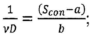
US 6,019,505 , which is in this regard incorporated herein by reference in its entirety for teaching such determination. Preferably, D is determined by activating the at least one heater element in a heat-wave scheme, e.g. by increasing and decreasing the heating power in a sinusoidal manner. Accordingly, D may be determined from a time-varying heating scheme applied to said heater element. At least one temperature sensor spaced at a certain distance measures the propagation of a heat wave generated by means of the heater element. The phase difference between the generated heat wave at the heater element and the at least one temperature sensor is a function of thermal diffusivity D. Preferably, instead of measuring the phase difference between the heater element and the one temperature sensor, two temperature sensors with different spacing to the heater element are used for measuring the diffusivity D (e.g. configuration as inFig. 4 ). In the two temperature-sensor configuration, the phase difference of the generated heat wave at the two temperature sensors (as shown e.g. inFig. 4 ) is a function of the thermal diffusivity D. This function may be determined by means of calibration measurements. This function may be determined beforehand by means of calibration measurements and implemented by the devices electronic means, e.g. by means of a lookup table. - Next, a zero gas-flow situation in the thermal sensor device may be established (i.e. no flow through the thermal sensor due to, for example, any pressure difference between gas inlet and outlet of said thermal sensor device or, in other words, without action of the heater element, no directed flows such as convection flows occur in the gas). Then, the heater element may be set to heat, preferably with constant heating power, to create the natural convection in the gas, around the heater. The temperature sensors are arranged to be exposed to the convection flows, whereby the convection may be evaluated. It is conceivable to use a varying heater power. The natural-convection parameter related signal Scon, i.e. the thermal sensor output under these conditions (e.g. at temperature difference or sum of the two temperature sensors), is read out from the at least one temperature sensor, preferably from two temperature sensors, the signal being the difference. It is also possible to include the heater element into the generation of the output (e.g. resistivity measurement). The thermal sensor output may be, for example, a temperature difference between two temperature sensors exposed to the natural convection, preferably sampling different locations in the convection flows at which different temperatures are present.
- The natural-convection parameter related signal Scon may be written in a polynomial expansion of the natural-
convection parameter 

- The thermal conductivity λ, the gas temperature T, as determined by measurement, and the expansion coefficients a, b, c etc. may therefore be used for deducing from the natural-convection related signal Scon of the thermal sensor device said natural-
convection parameter 
- linear expansion:
- quadratic expansion:

- From the natural-
convection parameter 

- It is to be understood that these three
parameters 

- In some embodiments, said thermal sensor device comprises, as said at least one temperature sensor, a first temperature sensor and a second temperature sensor, said heater element being arranged therebetween. This is the design of a known thermal flow sensor, e.g. on a membrane or bridge spanning a substrate cavity. By using at least two temperature sensors, one does not need to read out heater element related parameters (such as its resistance) for determining a temperature value but one simply uses the two temperature readings and uses, for example, the difference or sum as S con. Such a differential measurement is advantageous as the device degradation is reduced. Moreover, the heater element may be operated at lower temperatures. The differential temperature signal may be determined in a known manner. Moreover, these two temperature sensors may be part of a thermal flow sensor and therefore may be further used for measuring a flow of the gas g, if present, for determining the flows as described below.
- In some preferred embodiments, said first and second temperature sensors and said heater element are arranged on a bridge structure or on a membrane spanning a cavity in a substrate of said thermal sensor device. The first and second temperature sensors are preferably arranged such that, during measurement, they are spaced in a direction of gravitation. This measurement configuration could be called a vertical configuration. The heater may be arranged in or offset of a middle position of a distance between the two temperature sensors. Alternatively, a horizontal configuration may be used, i.e. the temperature sensors are spaced in a direction at right angles with gravitation. In a horizontal configuration, either the geometry of the device may be chosen such that the natural convection flows establish a temperature pattern that allows for determination of a significant signal that allows for determination of the natural-
convection parameter 
convection parameter 
- The method further comprises:
- determining a first temperature value T 1 at said first temperature sensor and a second temperature value at the second temperature sensor under action of the heater element;
- calculating said heat-transfer parameter, e.g. said thermal conductivity λ of said gas, said heat-capacity related parameter, e.g. said thermal diffusivity D or volumetric specific heat cpρ, said natural-
convection parameter 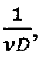
- In some embodiments, said heat-transfer parameter is the thermal conductivity λ and/or said heat-capacity related parameter is the thermal diffusivity D or a volumetric heat capacity cpρ of said gas of interest.
- In a further aspect of the present invention, furthermore, an absolute pressure of the gas is measured and a combustion parameter is determined.
- Accordingly, in some embodiments, additionally, an absolute pressure p of said gas is used or determined. The absolute pressure may be an input that is used or it may be a parameter that is determined by a pressure sensor or a pressure meter that is part of the device. A combustion parameter of said gas may then be calculated from said heat-transfer parameter, said heat-capacity related parameter, said natural-
convection parameter 
WO 2015/075278 A1 or inEP 3 153 854 A1 - Accordingly, the regression parameters are determined, for example, by means of a table of natural gases and gas parameters of these gases. Since, generally, these parameters depend on temperature T and pressure p, T and p are measured and considered. The temperature T may be measured on the chip, e.g. by a temperature sensor in the ASIC part; the pressure may be evaluated from a commercial pressure sensor or set by a pressure meter.
- In some embodiments, said combustion parameter is selected from the group comprising:
- a calorific value, preferably, heat of combustion per unit volume Hρ;
- a Wobbe index IW ; and
- a methane number NM.
- In some embodiments, said gas parameter is the Prandtl number Pr of said gas. For at least some natural gases, the hydrogen concentration may be directly inferred from the Prandtl number Pr. Accordingly, the present invention provides a simply and cost-efficient sensor for determining a hydrogen concentration of natural gas.
- In a further aspect of the present invention, a volumetric flow or velocity of said gas is measured by means of a flow sensor. The flow sensor may be an extra flow sensor. Preferably, however, the aforementioned first and second temperature sensors and the heater element therebetween are used, in a known manner, to determine the flow. In some embodiments, from said volumetric flow a volumetric flow at standard temperatures is determined. Accordingly, by including said flow sensor to the thermal sensor device, different flows including, for example, a volumetric flow, a volumetric flow at standard temperatures, a standard volumetric flow, or an energy flow may be determined.
- Accordingly, in some embodiments, said thermal sensor device is further configured as a thermal flow sensor. The thermal flow sensor may be configured in a manner as disclosed in
WO 01/98736 A1 EP 2 527 779 A1WO 2012/021999 A1 . Said method then comprises: - (i) establishing a gas flow in said gas;
- (ii) operating said thermal flow sensor exposed to said gas flow and generating a flow signal;
- (iii) establishing a zero flow in said gas;
- (iv) operating said thermal flow sensor (i.e. activate the heater element to create the natural convection (i.e. the self-convection) and read out the temperature sensors) exposed to said zero flow and generating a zero flow signal;
- (v) the thermal conductivity λ and the thermal diffusivity D of said gas are calculated from said output of the thermal sensor device;
- (vi) said natural-
convection parameter 
- (vii) the Prandtl number Pr is calculated from said natural-
convection parameter 
- a volumetric flow or a flow velocity is calculated based on said flow signal of the flow sensor, said thermal conductivity λ, said thermal diffusivity D, and said Prandtl number Pr of said gas.
- Alternatively or additionally, a volumetric flow at standard temperature may be calculated based on said temperature, said thermal conductivity λ, said thermal diffusivity D, and said Prandtl number Pr of said gas.
- The thermal flow sensor may be a standard thermal flow sensor including two temperature sensors and a heater element therebetween, whilst these components are arranged on a bridge or on a membrane structure. A membrane-type design and a bridge-type design of a thermal flow sensor are described in more detail in
WO 01/98736 A1 US 2004/0099057 A1 ,EP 1 840 535US 5,050,429 A , respectively; the disclosures of these documents is incorporated herein by reference in its entirety for teaching the setup of a thermal flow sensor. - In a further aspect, the thermal sensor is or includes a thermal flow sensor and an absolute pressure of the gas is used or determined, e.g. by an additional pressure sensor, whereupon a flow related parameter is determined considering the absolute pressure of the gas.
- Accordingly, in some embodiments, additionally, the absolute pressure p of said gas is used or determined; wherein a standard volumetric flow Q is calculated based said temperature of the gas, said absolute pressure p, and said volumetric flow V̇.
- In some embodiments, the absolute pressure p of said gas is used or determined; wherein an energy flow JE is calculated based on said combustion parameter as mentioned above and said volumetric flow V̇.
- In a further aspect, the present invention relates to a thermal sensor device that is able to determine a gas parameter based on calculation inputs including measured values such as the natural-convection parameter. More specifically, the present invention relates to a thermal sensor device for determining a gas parameter of a gas, the thermal sensor device comprising:
- at least one temperature sensor and at least one heater element and being exposed to said gas, said at least one temperature sensor and said at least one heater element being preferably arranged on a bridge structure or on a membrane spanning a cavity in a substrate of said thermal sensor device;
- a control device configured to carry out the following method:
- operating said thermal sensor device being exposed to said gas;
- calculating from an output of said thermal sensor device:
- (i) a temperature of said gas;
- (ii) a heat-transfer parameter of said gas;
- (iii) a heat-capacity related parameter of said gas;
- (iv) a natural-
convection parameter 
- calculating said gas parameter of said gas from said heat-transfer parameter, preferably the thermal conductivity λ of the gas, said heat-capacity related parameter, preferably a thermal diffusivity D or a volumetric specific heat cpρ, and said natural-
convection parameter 
- In some embodiments, said control device of the thermal sensor device may be configured to carry out the method according to any of the herein described embodiments of the present invention.
- In some embodiments, the thermal sensor device comprises two or more temperature sensors, wherein one or more of said at least one heater element is arranged between said temperature sensors and off-set from a middle point between said temperature sensors, preferably by 5% to 30% of a distance between said temperature sensors. The offset arrangement causes a different temperature signal at the first and at the second temperature sensor, wherein the difference may be used as a measure of the natural-convection parameter related to convection flows established in the gas of interest due to the action of the heater element.
- In some embodiments, the thermal sensor device is configured such that, when in use is use, said temperature sensors are arranged at a distance along the direction of gravitation. This arrangement allows for temperature readings from the first and second temperatures sensors for calculating the natural-convection related parameter. In such a configuration, the heater element may be arranged in the middle of the distance between the two temperature sensors; alternatively, it may be arranged offset of this middle point, e.g. by 5% to 30% of said distance between said temperature sensors.
- In a further aspect, the present invention relates to a thermal sensor system comprising the thermal sensor device according to invention and further comprising an absolute pressure sensor or a pressure meter for measuring and controlling, respectively, an absolute pressure p of said gas. The control device is further configured to carry out the method according to invention, for example for determination of a combustion parameter, the Prandtl number, or the hydrogen concentration of the gas as explained above.
- In some embodiments, the thermal sensor system further comprises a thermal flow sensor device, wherein said control device is configured to carry out the method according to invention for determining a volumetric flow, a flow velocity, a volumetric flow at standard temperature, a standard volumetric flow, and/or an energy flow. Accordingly, in some embodiments, additionally, the thermal sensor system is configured for using or determining the absolute pressure p of said gas, wherein a standard volumetric flow Q is calculated based said temperature of the gas, said absolute pressure p, and said volumetric flow V̇. In some embodiments, additionally, the thermal sensor system is configured for using or determining the absolute pressure p of said gas, wherein an energy flow JE is calculated based on said combustion parameter as mentioned above and said volumetric flow V̇.
- In a further aspect, the present invention relates to a non-transitory computer readable medium for thermal sensor device according to invention, said non-transitory computer readable medium being encoded with a computer program product comprising computer code that, when executed in a processor, carries out the method according to invention.
- The computer code may be provided in a source code, in a machine-executable code, or in any intermediate form of code-like object code. It can be provided as a computer program product on a computer-readable medium in tangible form, e.g. on a CD-ROM or on a Flash ROM memory element or similar, or it can be made available in the form of a network-accessible medium for download from one or more remote servers through a network.
- It is to be understood that these aspects will be better understood when considered with the description of the preferred embodiments below. Aspects may be combined with one another without departing from the scope of the appended claims and further embodiments may be formed with parts or all the features of the embodiments as described herein.
- Preferred embodiments of the invention are described in the following with reference to the drawings, which are for the purpose of illustrating the present preferred embodiments of the invention and not for the purpose of limiting the same. In the drawings,
- Fig. 1
- shows a schematic functional diagram of a thermal sensor device according to an embodiment of the present invention;
- Fig. 2
- shows in a schematic perspective view a thermal flow sensor according to a first embodiment that may be employed in the present invention;
- Fig. 3
- shows in a schematic perspective view a thermal flow sensor according to a second embodiment that may be employed in the present invention;
- Fig. 4
- shows in a schematic perspective view a thermal flow sensor according to a third embodiment that may be employed in the present invention;
- Fig. 5
- shows a flow diagram of an embodiment of the method according to the present invention;
- Fig. 6
- correlation between the correlation calculation and Hρ;
- Fig. 7
- the relative error related to
Fig. 6 ; - Fig. 8
- the relative error when calculating the volume percentage of H2 gas in CH4 gas;
- Fig. 9
- shows a diagram that correlates the volume percentage of H2 gas in CH4 gas and the corresponding Prandtl number; and
- Fig. 10
- shows a simplified block diagram of a digital control circuit that can be employed in the present invention.
-
Figure 1 shows a schematic functional diagram of athermal sensor device 1 according to an embodiment of the present invention. A gas g of interest is present involume 15 and is exposed to aheater element 3. Natural convection due to heat and gravitation establishes (no other significant flow driver is present). First andsecond temperature sensors structure 11 or amembrane 12 spanning a cavity in asubstrate 14. The first andsecond temperature sensors sensors temperature sensors heater element 3 is used as a further temperature sensor (e.g. by reading out its resistance, indicated by the dashed-dotted lines). In some embodiments, see below, anabsolute pressure sensor 5 or pressure meter 6 is arranged for determining an absolute pressure p of the gas g (see dashed lines). Acontrol device 4 receives readings from thesensors 21, 22 (in some embodiments 3), and possibly 5 or 6. From these values, thecontrol device 4 calculates a gas parameter of the gas g. According to invention, the following parameters are measured: - (i) a temperature T of said gas g;
- (ii) a heat-transfer parameter such as the thermal conductivity λ of said gas g;
- (iii) a heat-capacity related parameter such as the thermal diffusivity D or the volumetric specific heat cpρ of said gas g; and
- (iv) a natural-
convection parameter 
heater element 3. - Then, the Prandtl number Pr, an H2 concentration CH, or a combustion parameter such as a heat of combustion per unit volume Hρ, a Wobbe index IW, or a methane number NM of said gas g is calculated from said heat-transfer parameter, said heat-capacity related parameter, said temperature T, said natural-
convection parameter 
-
Figure 1 is highly schematic. It is to be understood, that bothtemperature sensors heater element 3. Thesensors Fig. 2 ) or on a membrane (seeFig. 3 ) that span acavity 13. Thecavity 13 may be part of thevolume 15. Thesensors EP 1 426 740 -
Figures 2, 3 and4 show preferred embodiments of thethermal sensor device 1. -
Figure 2 shows thethermal sensor device 1 embodied by having asubstrate 14 into which acavity 13 is formed. Thecavity 13 is spanned by amembrane 12. On themembrane 12 are arranged thetemperature sensors heater element 3 for thermally decoupling them from thesubstrate 14 the latter tending to receive waste heat from electronic component supported thereon. Themembrane 12 is arranged vertically, i.e. during measurement, thedevice 1 is oriented such that themembrane 12 extends parallel to the gravitational direction G. Thetemperature sensors temperature sensors heater element 3 is arranged in-between the twotemperature sensors -
Figure 3 shows a second embodiment, where instead of a vertical membrane 12 a bridgingstructure 11 is spanning thecavity 13, wherein the first andsecond temperature sensors heater element 3 are arranged on the bridgingstructure 11 for decoupling it from thesubstrate 14. - In the
Figs. 2 and 3 , theheater element 3 may be arranged at or offset (by 5% to 30% or a distance or 21 to 22) to a middle point P between the first andsecond temperature sensors -
Figure 4 shows a third embodiment, where the bridgingstructure 11 is extending at right angles to the gravitational direction G, at least during measurement. Accordingly, the first andsecond temperature sensors heater element 3 is arranged offset (by 5% to 30% or a distance or 21 to 22) to a middle point P between the first andsecond temperature sensors second temperature sensors heater 3 action in the gas g. - It is also conceivable to use such an asymmetric arrangement of the first and
second temperature sensors heater element 3 in a vertical arrangement, i.e. indevices 1 where themembrane 12 or bridgingstructure 11 is oriented parallel to the gravitational direction G. This would further enhance the precision of the measurement. -
Figure 5 shows possible implementations of the method according to invention. - In
step 601, the temperature T may be determined by using the first orsecond temperature sensor thermal sensor device 1 according to any one ofFigs. 2 to 4 or another temperature sensor that may be arranged on the substrate of the sensor chip with thethermal sensor device 1, for example, on its ASIC part. - In
step 602, theheater element 3 is operated and the thermal conductivity λ of the gas g is calculated from signal related to a temperature/heater measurement scheme as taught, for example, inUS 6,019,505 . Accordingly, the maximum temperature measured at the first/and orsecond temperature sensors 21, 22 (or at sum or difference of the maximum temperatures measured at the first/and orsecond temperature sensors 21, 22) with theheater element 3 at a predefined setting (e.g. at maximum heating power) is an inverse function of the thermal conductivity λ. The inverse function may be determined by means of calibration measurements. Instep 603, theheater element 3 is operated and the thermal diffusivity D of the gas g which is from signal related to a temperature/heater measurement scheme as taught, for example, inUS 6,019,505 . Accordingly, the first andsecond temperature sensors heater element 3 and measure the propagation of a heat wave generated by means of theheater element 3. The phase difference between the generated heat wave at theheater element 3 and the first and/orsecond temperature sensor 21/22 or the phase difference of said wave between the two temperature sensors (as shown e.g. inFig. 4 ) is a function of the thermal diffusivity D. This function may be determined by means of calibration measurements. - In
step 604, the natural-convection parameter 
heater element 3, preferably to heat at constant power, whereby the macroscopic flow in the gas g is due to the action of theheater element 3, said macroscopic flow being a natural convection flow as indicated by the elliptical closed arrows in theFigs. 1 to 4 . From the temperature readings T 1 , T 2 of the first andsecond temperature sensors control device 4 for calculating the natural-convection parameter 
convection parameter 

- In
step 605, the thermal conductivity λ and the gas temperature T, as determined by thecontrol device 4 insteps thermal sensor device 1 said natural-convection parameter 
- linear expansion:

- quadratic expansion:

- In
step 606, the gas parameter is calculated. From the natural-convection parameter 

- In
step 607, the gas parameter is output to the user or further devices. - In some embodiments, from the Prandtl number Pr one may determine, e.g. by means of a lookup table that stores a beforehand established correlation of the Prandtl number and the hydrogen concentration, a hydrogen concentration C H of a natural gas g of interest. The hydrogen concentration is the volume percentage of H2 gas in the natural gas. Such a correlation is depicted in
Figure 9 . Accordingly, thisthermal sensor device 1 may be used to identify a gas that is, for example, a binary mixture of a natural gas and a H2 gas. - In a further development, a thermal sensor system 10 (see
Fig. 1 , dashed lines) may comprise such athermal sensor device 1 and may be further configured that the absolute pressure p of the gas g is received and considered or is directly measured by means of theabsolute pressure sensor 5 or set by means of the pressure meter 6. Acquiring the information on the absolute pressure p is indicated inFig. 5 asoptional step 608 and inFig. 1 by the dashed lines. - At this point, the
control device 4 has available the three parameters (i) thermal conductivity λ, (ii) thermal diffusivity D, (iii) Prandtl number Pr, and in addition the absolute gas temperature T and the absolute gas pressure p. - Preferably, the temperature sensor for determining the absolute gas temperature T is arranged on the ASIC part of the sensor chip with the
thermal sensor device 1. The absolute pressure may be measured by means of a separate commerciallyavailable pressure sensor 5. - The combustion parameter may be determined by using a quadratic Ansatz as taught, for example, in
WO 2015/075278 A1 ,EP 3 153 854 A1EP 2 015 056 - In the following, a specific example shall be demonstrated. The correlation between the parameter set (λ,D,vD) and the Hp, the heat of combustion per unit volume, shall presented for CH4, CH4 with up to 2 vol.% of H2 gas, CH4 with 2 to 5 vol.% of H2 gas, and CH4 with 5 to 10 vol.% of H2 gas at standard conditions. Under standard conditions - for this example, a standard pressure p 0=0.10132 MPa and at a standard temperature T=25°C-, one may us the following regress function:


- Through minimization of the root-mean-square error one finds:

-
Figure 6 shows the correlation between the fit and Hp,Figure 7 the relative error. The correlation is obvious, the correlation coefficient being R2 = 0.988. -
β Hρ depends on absolute gas temperature T and the absolute gas pressure p.β Hρ (T,p) may be determined by means of calibration and stored in thecontrol device 4 in one or more lookup tables LUT. - Other combustion parameters such as the Wobbe index IW , the methane number NM, or the like may be determined as taught, for example, in
WO 2015/075278 A1 ,EP 3 153 854 A1EP 2 015 056 - Moreover, the H2 concentration C H in a natural gas such as methane may be determined in a correlative manner. Using again the formula:


-
Figure 8 shows the relative error of this correlation. - From this coefficient set
β H2 one can see that x3 = 4.9 has a dominating weight, which is why the Prandtl number being associated with x3 has a dominating weight and may therefore be used as direct measurement for the H2 concentration C H as shown inFigure 10 , showing a binary gas mixture of CH4 and H2. A physical explanation would be that the H2 molecules are considerably smaller than the CH4 molecules. - In a further development, the
thermal sensor system 10 may comprise aflow sensor 7 for determining a volumetric flow
pressure sensor 5 ormeter 5 but does not have to. - The zero-flow condition for the measurement of the natural convection parameter or other parameters may be established in the flow channel or it may be established in a dead volume in communication with the flow channel during the flow of the gas through the flow channel.
- If then a gas flow of the gas g is present, the
flow sensor 7 picks up a flow signal S flow. This flow signal S flow is related to the volumetric flow V by the following relation:


- If the gas of interest is known, the function Fλ,Pr and/or its reverse function

system 10 by storing it to the non-volatile memory. One may use a lookup table. If the gas is unknown, a parameter set D, λ, Pr may first be determined of the unknown gas g. The reverse function
EP 3 153 854 A1control device 4 and may be output instep 607. - From the volumetric flow V a volumetric flow at standard temperature, F, may be calculated, the standard temperature T 0 being, for example, T 0=25°C, by the
control device 4, by using the relation:
- If, furthermore, the absolute pressure p of the gas is known (by receiving or measuring it), the following flows may be calculated by the system 10:


- These flows may be outputted to a user or used by further devices as the gas parameter of interest.
-
Figure 10 shows a schematic block diagram of adigital control device 4. Thecontrol device 4 comprises a processor (CPU, µP) 84, a non-volatile (e.g. Flash ROM)memory 81, and a volatile (RAM)memory 83. Theprocessor 84 communicates with thememory modules more data buses 85. Thenon-volatile memory 81 stores, inter alia, sets ofcalibration data 86, e.g. in form of one or more lookup tables LUT, and other data required for the calculation of the target gas parameter, as well as a machine-executable program 82 for execution in theprocessor 84. The calibration data may include a correlation between a hydrogen concentration C H (i.e. volume % of H2 gas in the gas g) and a Prandtl number Pr of one or more gases. It may contain expansion coefficients (in dependence of temperature T and thermal conductivity λ of the gas) for calculation of the natural-convection relatedparameter 
- The
processor 84 may communicate, through a device interface (IF) 87, with various peripherals, which may include, for example, at least one input/output (I/O)interface 88 for interfacing with an external input/output device such as a keyboard and/or mouse, an LCD screen, etc., with the first andsecond temperature sensors heater element 3, and, if any, with thepressure sensor 5, the pressure meter 6, or theflow sensor 7, via its built-indigital circuitry 89. - Accordingly, the present invention relates to a device that comprises a
thermal sensor 1, the thermal sensor being preferably a thermal flow sensor, with two ormore temperature sensors heater element 3 arranged therebetween, thetemperature sensors heater element 3 may be arranged on amembrane 12 or on a bridgingstructure 11. By means of the thermal sensor, the parameter set (D, λ, Pr) (or an equivalent set of parameters such as, for example, (D, λ, cpρ)) may be determined as described herein. The temperature T of the gas g may be determined by means of the first orsecond temperature sensor device 1 orsystem 10. Further, in a preferred embodiment, anabsolute pressure sensor 5 or pressure meter 6 is added to thedevice 1, thereby creating a simplethermal sensor system 10. By means of the absolute pressure sensor value p, combustion parameters such as the Wobbe index, the methane number, or the combustion heat or others become available as gas parameter output of thesystem 10. The flow sensor and pressure sensor may be included separately to thethermal sensor 1 or both together, depending on the required output gas parameter. Thecontrol device 4 is configured to perform the calculations as outlined above for the different embodiments of thedevice 1 orsystem 10. Thedevice 1 orsystem 10 is small, compact, cost-efficient and reliable. By means of thesystem 10, a gas quality system may be provided. In some embodiments, thisdevice 1 orsystem 10 allows for determination of an H2 concentration in a gas.LIST OF REFERENCE SIGNS 1 thermal sensor device 88 input/ output interface 10 thermal sensor system 89 circuitry 11 bridge structure CH Hydrogen concentration in g 12 membrane cpρ volumetric heat capacity 13 cavity in 14 d distance between 21, 22 14 substrate of 1 D thermal diffusivity 15 volume f gas flow f 0 zero gas flow 2 temperature sensor g gas 21 first temperature sensor Hρ Calorific value of g 22 second temperature sensor IW Wobbe index of g JE energy flow 3 heater element NM Methane number of g 4 control device P absolute pressure of g 5 pressure sensor P middle point of d 6 pressure meter or controller Pr Prandtl number of g 7 thermal flow sensor Q standard volumetric flow S con natural-convection signal 601-609 method steps S flow flow signal S flow,0 zero flow signal 81 non-transitory computer readable medium, non-volatile memory T temperature value of g T 1 first temperature value T 2 second temperature value 82 computer program product V̇ 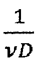
volumetric flow 83 volatile memory flow velocity 84 processor natural- convection parameter 85 bus λ thermal conductivity of g 86 calibration data, lookup table(s) LUT 87 device interface

Claims (17)
- A method for determining a gas parameter (Pr;CH;Hρ; IW ; NM ) of a gas (g), said method comprising:- operating a thermal sensor device (1) being exposed to said gas (g) and comprising at least one temperature sensor (2;21,22) and at least one heater element (3);- calculating from an output of said thermal sensor device (1):(i) a temperature (T) of said gas (g);(ii) a heat-transfer parameter (λ) of said gas (g);(iii) a heat-capacity related parameter (D; cpρ) of said gas (g);(iv) a natural-convection parameter
 - calculating said gas parameter (Pr;CH;Hρ; IW ; NM ) of said gas (g) from said heat-transfer parameter (λ), said heat-capacity related parameter (D; cpρ), and said natural-convection parameter
- The method according to claim 1, wherein said natural-convection parameter


wherein, preferably, expansion terms of said expansion are empirically determined functions of said heat-transfer parameter (λ) and said temperature (T) of said gas (g); and/or
wherein, preferably, said expansion is made up to a linear term or to a quadratic terms. - The method according to claim 1 or 2, wherein said heat-transfer parameter (λ) of said gas (g) is determined from a stationary temperature distribution in said fluid (g) caused by said at least one heater element (3).
- The method according to any one of claims 1 to 3, wherein said heat-capacity related parameter (D; cpρ) of said gas (g) is determined from a time-varying heating scheme applied to said heater element (3).
- The method according to any one of claims 1 to 4, wherein said thermal sensor device (1) comprises, as said at least one temperature sensor (3), a first temperature sensor (21) and a second temperature sensor (22), said heater element (3) being arranged therebetween, said first and second temperature sensors (21,22) and said heater element (3) being preferably arranged on a bridge structure (11) or a membrane (12) spanning a cavity (13) in a substrate (14) of said thermal sensor device (1);
and wherein said method comprises:determining a first temperature value (T 1) at said first temperature sensor (21) and a second temperature value (T 2) at the second temperature sensor (22) under action of the heater element (3);calculating said heat-transfer parameter (λ), said heat-capacity related parameter (D; cpρ), said natural-convection parameter
- The method according to claim 5, wherein the heater element (3) is arranged between said first and second temperature sensors (21,22) in a manner off-set from a middle point (P) between said temperature sensors (21,22), preferably by 5% to 30% of a distance (d) between said temperature sensors (21,22); and/or
wherein the thermal sensor device (1) is used such that said first and second temperature sensors (21,22) are separated along the direction of gravitation. - The method according to any one of claims 1 to 6, wherein said heat-transfer parameter (λ) is a thermal conductivity (λ) and/or said heat-capacity related parameter (D; cpρ) is a thermal diffusivity (D) or a volumetric heat capacity (cpρ) of said gas (g).
- The method according to any one of claims 1 to 7, wherein, additionally, an absolute pressure (p) of said gas (g) is used or determined, and as said gas parameter a combustion parameter (Hρ; IW ; NM ) of said gas (g) is calculated from said heat-transfer parameter (λ), said heat-capacity related parameter (D; cpρ), said natural-convection parameter

- The method according to claim 8, wherein said combustion parameter (Hρ; IW ; NM ) is selected from the group comprising:a calorific value, preferably, a heat of combustion per unit volume (Hρ);a Wobbe index (IW ); anda methane number (NM).
- The method according to any one of the claims 1 to 9, wherein said gas parameter is the Prandtl number (Pr) of said gas (g), or wherein said gas (g) is a natural gas and said gas parameter is a hydrogen concentration (CH ) of said gas (g).
- The method according to claim 10, said thermal sensor device (1) being further configured as a thermal flow sensor (7), wherein said method comprises:(i) establishing a gas flow (f) in said gas (g);(ii) operating said thermal flow sensor (7) exposed to said gas flow (f) and generating a flow signal (S flow);(iii) establishing a zero gas flow (f 0) in said gas (g), preferably at constant heating power to the heating element (3);(iv) operating said thermal flow sensor (7) exposed to said zero gas flow (f 0) and generating a zero flow signal (S flow,0);wherein:(v) the thermal conductivity (λ) and the thermal diffusivity (D) of said gas (g) are calculated from said output of the thermal sensor device (1);(vi) said natural-convection parameter
 (vii) the Prandtl number (Pr) is calculated from said natural-convection parameterand wherein:
 (vii) a volumetric flow (V̇) or a flow velocity (v) is calculated based on said flow signal (S flow), said thermal conductivity (λ), said thermal diffusivity (D), and said Prandtl number (Pr) of said gas (g); and/or(viii) a volumetric flow at standard temperature (F) is calculated based on said flow signal (S flow), said temperature (T), said thermal conductivity (λ), said thermal diffusivity (D), and said Prandtl number (Pr) of said gas (g).
 - The method according to claim 11, wherein, additionally, an absolute pressure (p) of said gas (g) is used or determined by means of an absolute pressure sensor (5) or a pressure meter (6); wherein:(i) a standard volumetric flow (Q) is calculated based said temperature (T), said absolute pressure (p), and said volumetric flow (V̇); and/or(ii) an energy flow (JE) is calculated based on said combustion parameter (Hρ; IW ; NM ) according to claim 8 or 9 and said volumetric flow (V̇).
- A thermal sensor device (1) for determining a gas parameter (Pr;CH;Hρ; IW ; NM ) of a gas (g), the thermal sensor device (1) comprising:at least one temperature sensor (2;21,22) and at least one heater element (3) and being exposed to said gas (g), said at least one temperature sensor (2;21,22) and said at least one heater element (3) being preferably arranged on a bridge structure (11) or on a membrane (12) spanning a cavity (13) in a substrate (14) of said thermal sensor device (1);a control device (4) configured to carry out the following method:- operating said thermal sensor device (1) being exposed to said gas (g);- calculating from an output of said thermal sensor device (1):(i) a temperature (T) of said gas (g);(ii) a heat-transfer parameter (λ) of said gas (g);(iii) a heat-capacity related parameter (D; cpρ) of said gas (g);(iv) a natural-convection parameter
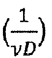 - calculating said gas parameter (Pr;CH;Hρ; IW ; NM ) of said gas (g) from said heat-transfer parameter (λ), said heat-capacity related parameter (D; cpρ), and said natural-convection parameter
 wherein, preferably, said control device (4) is further configured to carry out the method according to any one of the claims 2 to 7 or 10.
 - The thermal sensor device (1) according to claim 13, comprising two or more temperature sensors (21,22), wherein one or more of said at least one heater element (3) is arranged between said temperature sensors (21,22) and off-set from a middle point (P) between said temperature sensors (21,22), preferably by 5% to 30% of a distance (d) between said temperature sensors (21,22); and/or
wherein, with the thermal sensor device (1) is use, said temperature sensors (21,22) are arranged at a distance along the direction of gravitation. - A thermal sensor system (10) comprising the thermal sensor device (1) according to claim 13 or 14 and further comprising an absolute pressure sensor (5) or a pressure meter (6) for measuring and controlling, respectively, an absolute pressure (p) of said gas (g);
wherein said control device (4) is further configured to carry out the method according to any one of the claims 8 to 10. - A thermal sensor device (1) according to claim 13 or 14, or a thermal sensor system (10) according to claim 15, further comprising a thermal flow sensor device (7), wherein said control device (4) is configured to carry out the method according to claim 11 or 12.
- A non-transitory computer readable medium (81) for thermal sensor device (1) according to claim 13 or 14 or 15, or a thermal sensor system (10) according to claim 15 or 16, said non-transitory computer readable medium (81) being encoded with a computer program product (82) comprising computer code that, when executed in a processor (84), carries out the method according to any one of the claims 1 to 12.
Priority Applications (2)
| Application Number | Priority Date | Filing Date | Title |
|---|---|---|---|
| EP17208745.4A EP3502687B1 (en) | 2017-12-20 | 2017-12-20 | Determination of gas parameters |
| CN201811553775.6A CN110031503A (en) | 2017-12-20 | 2018-12-18 | The determination of gas parameter |
Applications Claiming Priority (1)
| Application Number | Priority Date | Filing Date | Title |
|---|---|---|---|
| EP17208745.4A EP3502687B1 (en) | 2017-12-20 | 2017-12-20 | Determination of gas parameters |
Publications (2)
| Publication Number | Publication Date |
|---|---|
| EP3502687A1 true EP3502687A1 (en) | 2019-06-26 |
| EP3502687B1 EP3502687B1 (en) | 2022-06-29 |
Family
ID=60781770
Family Applications (1)
| Application Number | Title | Priority Date | Filing Date |
|---|---|---|---|
| EP17208745.4A Active EP3502687B1 (en) | 2017-12-20 | 2017-12-20 | Determination of gas parameters |
Country Status (2)
| Country | Link |
|---|---|
| EP (1) | EP3502687B1 (en) |
| CN (1) | CN110031503A (en) |
Cited By (9)
| Publication number | Priority date | Publication date | Assignee | Title |
|---|---|---|---|---|
| US20200333273A1 (en) * | 2018-01-05 | 2020-10-22 | Hahn-Schickard-Gesellschaft für angewandte Forschung e.V. | Evaluation arrangement for a thermal gas sensor, methods and computer programs |
| EP3812753A1 (en) | 2019-10-24 | 2021-04-28 | Sensirion AG | Determination of gas-specific parameters from heat transfer in the temperature jump regime |
| US11454622B2 (en) | 2018-01-05 | 2022-09-27 | Hahn-Schickard-Gesellschaft für angewandte Forschung e.V. | Gas sensor, and method for operating the gas sensor |
| CN116415618A (en) * | 2023-04-18 | 2023-07-11 | 北京华能长江环保科技研究院有限公司 | Method, device, electronic equipment and medium for obtaining structural parameters of sonic nozzle |
| DE102022208018B3 (en) | 2022-08-03 | 2023-10-05 | Vitesco Technologies GmbH | Method and gas sensor for determining the concentration of a gas component in a gas mixture |
| US12304810B2 (en) | 2021-05-21 | 2025-05-20 | Sensirion Ag | Gas generator |
| US12474285B2 (en) | 2023-03-17 | 2025-11-18 | Honeywell International, Inc. | Closed-meshed energy measurement in the gas network |
| JP2026015237A (en) * | 2024-07-18 | 2026-01-29 | ライフ セーフティ ディストリビューション ゲーエムベーハー | Thermal conductivity sensor for detecting gases |
| JP2026507165A (en) * | 2023-03-16 | 2026-02-27 | インナー センサー カンパニー リミテッド | Gas Sensing Element |
Families Citing this family (3)
| Publication number | Priority date | Publication date | Assignee | Title |
|---|---|---|---|---|
| CN111308023A (en) * | 2020-04-10 | 2020-06-19 | 深圳矽递科技股份有限公司 | An ambient gas sensor |
| EP4273514B1 (en) * | 2022-05-06 | 2024-09-18 | Abb Schweiz Ag | System and method for determining at least one calculated process parameter of a fluid in a pipe |
| DE102024203126B3 (en) * | 2024-04-05 | 2025-08-28 | Schaeffler Technologies AG & Co. KG | Method, control device, gas analysis device and computer program for determining the hydrogen content in a gas mixture, as well as vehicle and computer-readable medium |
Citations (14)
| Publication number | Priority date | Publication date | Assignee | Title |
|---|---|---|---|---|
| US5050429A (en) | 1990-02-22 | 1991-09-24 | Yamatake-Honeywell Co., Ltd. | Microbridge flow sensor |
| US6019505A (en) | 1997-12-31 | 2000-02-01 | Honeywell Inc. | Time lag approach for measuring thermal conductivity and specific heat |
| WO2001098736A1 (en) | 2000-06-23 | 2001-12-27 | Sensirion Ag | Gas meter and method for detecting a consumed amount of gas |
| DE10122039A1 (en) | 2001-05-07 | 2002-11-14 | Ruhrgas Ag | Method and device for determining a characteristic value representative of the nature of a gas |
| US20040099057A1 (en) | 2002-11-27 | 2004-05-27 | Sensirion Ag | Device and method for measuring the flow and at least one material parameter of a fluid |
| EP1840535A1 (en) | 2006-03-31 | 2007-10-03 | Sensirion AG | Flow sensor with thermocouples |
| EP2015056A1 (en) | 2007-07-07 | 2009-01-14 | Mems Ag | Method and sensor for determining a significant value in combustibility terms of a gas mixture |
| US20100154510A1 (en) * | 2008-12-19 | 2010-06-24 | Institut National D'optique | Method for sensing gas composition and pressure |
| US20110126611A1 (en) * | 2009-12-01 | 2011-06-02 | Continental Automotive Gmbh | Hydrogen Sensor and A Detection Method for Hydrogen Concentration |
| WO2012021999A1 (en) | 2010-08-17 | 2012-02-23 | Sensirion Ag | Flow sensor arrangement |
| EP2527779A2 (en) | 2011-05-25 | 2012-11-28 | Raytheon Company | Retractable rotary laser turret |
| WO2015075278A1 (en) | 2015-03-05 | 2015-05-28 | Sensirion Ag | Determination of fluid parameters |
| US20160138951A1 (en) * | 2014-11-14 | 2016-05-19 | Mems Ag | Method and measuring apparatus for determining specific quantities for gas quality |
| EP3153854A1 (en) | 2015-10-05 | 2017-04-12 | Sensirion AG | Determination of combustion parameters from physical gas parameters |
Family Cites Families (2)
| Publication number | Priority date | Publication date | Assignee | Title |
|---|---|---|---|---|
| CN109946195B (en) * | 2013-05-24 | 2022-06-07 | Mems股份公司 | Method and device for determining physical properties of a gas |
| CN105806886A (en) * | 2016-03-16 | 2016-07-27 | 新奥科技发展有限公司 | Method and device for measuring heat value of gas |
-
2017
- 2017-12-20 EP EP17208745.4A patent/EP3502687B1/en active Active
-
2018
- 2018-12-18 CN CN201811553775.6A patent/CN110031503A/en active Pending
Patent Citations (15)
| Publication number | Priority date | Publication date | Assignee | Title |
|---|---|---|---|---|
| US5050429A (en) | 1990-02-22 | 1991-09-24 | Yamatake-Honeywell Co., Ltd. | Microbridge flow sensor |
| US6019505A (en) | 1997-12-31 | 2000-02-01 | Honeywell Inc. | Time lag approach for measuring thermal conductivity and specific heat |
| WO2001098736A1 (en) | 2000-06-23 | 2001-12-27 | Sensirion Ag | Gas meter and method for detecting a consumed amount of gas |
| DE10122039A1 (en) | 2001-05-07 | 2002-11-14 | Ruhrgas Ag | Method and device for determining a characteristic value representative of the nature of a gas |
| US20040099057A1 (en) | 2002-11-27 | 2004-05-27 | Sensirion Ag | Device and method for measuring the flow and at least one material parameter of a fluid |
| EP1426740A2 (en) | 2002-11-27 | 2004-06-09 | Sensirion AG | Device for measuring the flow and at least one material parameter of a fluid |
| EP1840535A1 (en) | 2006-03-31 | 2007-10-03 | Sensirion AG | Flow sensor with thermocouples |
| EP2015056A1 (en) | 2007-07-07 | 2009-01-14 | Mems Ag | Method and sensor for determining a significant value in combustibility terms of a gas mixture |
| US20100154510A1 (en) * | 2008-12-19 | 2010-06-24 | Institut National D'optique | Method for sensing gas composition and pressure |
| US20110126611A1 (en) * | 2009-12-01 | 2011-06-02 | Continental Automotive Gmbh | Hydrogen Sensor and A Detection Method for Hydrogen Concentration |
| WO2012021999A1 (en) | 2010-08-17 | 2012-02-23 | Sensirion Ag | Flow sensor arrangement |
| EP2527779A2 (en) | 2011-05-25 | 2012-11-28 | Raytheon Company | Retractable rotary laser turret |
| US20160138951A1 (en) * | 2014-11-14 | 2016-05-19 | Mems Ag | Method and measuring apparatus for determining specific quantities for gas quality |
| WO2015075278A1 (en) | 2015-03-05 | 2015-05-28 | Sensirion Ag | Determination of fluid parameters |
| EP3153854A1 (en) | 2015-10-05 | 2017-04-12 | Sensirion AG | Determination of combustion parameters from physical gas parameters |
Cited By (15)
| Publication number | Priority date | Publication date | Assignee | Title |
|---|---|---|---|---|
| US11874242B2 (en) | 2018-01-05 | 2024-01-16 | Habn-Schickard-Gesellschaft für angewandte Forschung e.V. | Evaluation arrangement for a thermal gas sensor, methods and computer programs |
| US11454622B2 (en) | 2018-01-05 | 2022-09-27 | Hahn-Schickard-Gesellschaft für angewandte Forschung e.V. | Gas sensor, and method for operating the gas sensor |
| AU2022200416B2 (en) * | 2018-01-05 | 2023-06-15 | GS Elektromedizinische Geräte G. Stemple GmbH | Evaluation arrangement for a thermal gas sensor, methods and computer programs |
| US11686695B2 (en) * | 2018-01-05 | 2023-06-27 | Hahn-Schickard-Gesellschaft für angewandte Forschung e.V. | Evaluation arrangement for a thermal gas sensor, methods and computer programs |
| US12385862B2 (en) | 2018-01-05 | 2025-08-12 | Hahn-Schickard-Gesellschaft für angewandte Forschung e.V. | Evaluation arrangement for a thermal gas sensor, methods and computer programs |
| US20200333273A1 (en) * | 2018-01-05 | 2020-10-22 | Hahn-Schickard-Gesellschaft für angewandte Forschung e.V. | Evaluation arrangement for a thermal gas sensor, methods and computer programs |
| EP3812753A1 (en) | 2019-10-24 | 2021-04-28 | Sensirion AG | Determination of gas-specific parameters from heat transfer in the temperature jump regime |
| US12304810B2 (en) | 2021-05-21 | 2025-05-20 | Sensirion Ag | Gas generator |
| WO2024028217A1 (en) | 2022-08-03 | 2024-02-08 | Vitesco Technologies GmbH | Method and gas sensor for ascertaining the concentration of a gas component in a gas mixture |
| DE102022208018B3 (en) | 2022-08-03 | 2023-10-05 | Vitesco Technologies GmbH | Method and gas sensor for determining the concentration of a gas component in a gas mixture |
| JP2026507165A (en) * | 2023-03-16 | 2026-02-27 | インナー センサー カンパニー リミテッド | Gas Sensing Element |
| JP7892307B2 (en) | 2023-03-16 | 2026-07-21 | インナー センサー カンパニー リミテッド | gas sensing element |
| US12474285B2 (en) | 2023-03-17 | 2025-11-18 | Honeywell International, Inc. | Closed-meshed energy measurement in the gas network |
| CN116415618A (en) * | 2023-04-18 | 2023-07-11 | 北京华能长江环保科技研究院有限公司 | Method, device, electronic equipment and medium for obtaining structural parameters of sonic nozzle |
| JP2026015237A (en) * | 2024-07-18 | 2026-01-29 | ライフ セーフティ ディストリビューション ゲーエムベーハー | Thermal conductivity sensor for detecting gases |
Also Published As
| Publication number | Publication date |
|---|---|
| CN110031503A (en) | 2019-07-19 |
| EP3502687B1 (en) | 2022-06-29 |
Similar Documents
| Publication | Publication Date | Title |
|---|---|---|
| EP3502687B1 (en) | Determination of gas parameters | |
| US11226300B2 (en) | Determination of fluid parameters | |
| JP6731936B2 (en) | MEMS thermal type flow sensor and method for measuring fluid flow rate | |
| AU2016200479B2 (en) | Device and method for determining the mass-flow of a fluid | |
| CN102778472B (en) | Calorific value measuring system and calorific value measuring method | |
| EP3153854B1 (en) | Determination of volumetric flow rate of a gas in a gas flow | |
| KR102234155B1 (en) | System and method for correcting current value of shunt resistor | |
| US9671266B2 (en) | Method for thermally determining mass flow of a gaseous medium and thermal mass flow meter | |
| US9702745B2 (en) | Characterizing multiphase fluid flow | |
| EP3540382B1 (en) | Airflow sensor with gas composition correction | |
| CN102027333A (en) | Multivariable process fluid flow device with energy flow calculation | |
| BRPI0419043B1 (en) | Method and apparatus for providing thermal compensation for a coriolis flowmeter | |
| Bernhardsgrütter et al. | Fluid-compensated thermal flow sensor: A combination of the 3ω-method and constant temperature anemometry | |
| JP2007139672A (en) | Fluid measuring device and fluid measuring method | |
| Azadi Kenari et al. | Gas-compensated thermal flow sensor using an integrated velocity-independent gas properties meter | |
| JP5690003B2 (en) | Specific heat capacity measurement system and flow rate measurement system | |
| CN101964006B (en) | Method and device for calculating temperature dependent Green function by using weight function | |
| CN101087997A (en) | Automatic thermal conductivity compensation for fluid flow sensing using chemometrics | |
| JP3889404B2 (en) | Concentration measuring method, concentration measuring system, and concentration measuring program | |
| JP4013755B2 (en) | Differential pressure measuring device | |
| CN103162771B (en) | The scaling method of apparatus for metering fluids | |
| JP4907959B2 (en) | Flow sensor correction unit, fluid discrimination device, and flow measurement device | |
| EP4495563A1 (en) | Method for determining an uncertainty range for a measurement value of a model-based measuring device | |
| Silin et al. | Hydrodynamic transition delay in rectangular channels under high heat flux | |
| JP2014160082A (en) | Calorie component concentration measuring system and flow measurement system |
Legal Events
| Date | Code | Title | Description |
|---|---|---|---|
| PUAI | Public reference made under article 153(3) epc to a published international application that has entered the european phase |
Free format text: ORIGINAL CODE: 0009012 |
|
| STAA | Information on the status of an ep patent application or granted ep patent |
Free format text: STATUS: THE APPLICATION HAS BEEN PUBLISHED |
|
| AK | Designated contracting states |
Kind code of ref document: A1 Designated state(s): AL AT BE BG CH CY CZ DE DK EE ES FI FR GB GR HR HU IE IS IT LI LT LU LV MC MK MT NL NO PL PT RO RS SE SI SK SM TR |
|
| AX | Request for extension of the european patent |
Extension state: BA ME |
|
| STAA | Information on the status of an ep patent application or granted ep patent |
Free format text: STATUS: REQUEST FOR EXAMINATION WAS MADE |
|
| 17P | Request for examination filed |
Effective date: 20190705 |
|
| RBV | Designated contracting states (corrected) |
Designated state(s): AL AT BE BG CH CY CZ DE DK EE ES FI FR GB GR HR HU IE IS IT LI LT LU LV MC MK MT NL NO PL PT RO RS SE SI SK SM TR |
|
| GRAP | Despatch of communication of intention to grant a patent |
Free format text: ORIGINAL CODE: EPIDOSNIGR1 |
|
| STAA | Information on the status of an ep patent application or granted ep patent |
Free format text: STATUS: GRANT OF PATENT IS INTENDED |
|
| RIC1 | Information provided on ipc code assigned before grant |
Ipc: G01N 27/18 20060101ALN20211209BHEP Ipc: G01N 25/18 20060101ALI20211209BHEP Ipc: G01N 33/22 20060101AFI20211209BHEP |
|
| INTG | Intention to grant announced |
Effective date: 20211223 |
|
| RIC1 | Information provided on ipc code assigned before grant |
Ipc: G01N 27/18 20060101ALN20211214BHEP Ipc: G01N 25/18 20060101ALI20211214BHEP Ipc: G01N 33/22 20060101AFI20211214BHEP |
|
| GRAJ | Information related to disapproval of communication of intention to grant by the applicant or resumption of examination proceedings by the epo deleted |
Free format text: ORIGINAL CODE: EPIDOSDIGR1 |
|
| STAA | Information on the status of an ep patent application or granted ep patent |
Free format text: STATUS: REQUEST FOR EXAMINATION WAS MADE |
|
| GRAP | Despatch of communication of intention to grant a patent |
Free format text: ORIGINAL CODE: EPIDOSNIGR1 |
|
| STAA | Information on the status of an ep patent application or granted ep patent |
Free format text: STATUS: GRANT OF PATENT IS INTENDED |
|
| INTC | Intention to grant announced (deleted) | ||
| RIC1 | Information provided on ipc code assigned before grant |
Ipc: G01N 27/18 20060101ALN20220204BHEP Ipc: G01N 25/18 20060101ALI20220204BHEP Ipc: G01N 33/22 20060101AFI20220204BHEP |
|
| INTG | Intention to grant announced |
Effective date: 20220223 |
|
| GRAS | Grant fee paid |
Free format text: ORIGINAL CODE: EPIDOSNIGR3 |
|
| GRAA | (expected) grant |
Free format text: ORIGINAL CODE: 0009210 |
|
| STAA | Information on the status of an ep patent application or granted ep patent |
Free format text: STATUS: THE PATENT HAS BEEN GRANTED |
|
| AK | Designated contracting states |
Kind code of ref document: B1 Designated state(s): AL AT BE BG CH CY CZ DE DK EE ES FI FR GB GR HR HU IE IS IT LI LT LU LV MC MK MT NL NO PL PT RO RS SE SI SK SM TR |
|
| REG | Reference to a national code |
Ref country code: CH Ref legal event code: EP |
|
| REG | Reference to a national code |
Ref country code: AT Ref legal event code: REF Ref document number: 1501668 Country of ref document: AT Kind code of ref document: T Effective date: 20220715 |
|
| REG | Reference to a national code |
Ref country code: IE Ref legal event code: FG4D |
|
| REG | Reference to a national code |
Ref country code: DE Ref legal event code: R096 Ref document number: 602017058964 Country of ref document: DE |
|
| REG | Reference to a national code |
Ref country code: LT Ref legal event code: MG9D |
|
| PG25 | Lapsed in a contracting state [announced via postgrant information from national office to epo] |
Ref country code: SE Free format text: LAPSE BECAUSE OF FAILURE TO SUBMIT A TRANSLATION OF THE DESCRIPTION OR TO PAY THE FEE WITHIN THE PRESCRIBED TIME-LIMIT Effective date: 20220629 Ref country code: NO Free format text: LAPSE BECAUSE OF FAILURE TO SUBMIT A TRANSLATION OF THE DESCRIPTION OR TO PAY THE FEE WITHIN THE PRESCRIBED TIME-LIMIT Effective date: 20220929 Ref country code: LT Free format text: LAPSE BECAUSE OF FAILURE TO SUBMIT A TRANSLATION OF THE DESCRIPTION OR TO PAY THE FEE WITHIN THE PRESCRIBED TIME-LIMIT Effective date: 20220629 Ref country code: HR Free format text: LAPSE BECAUSE OF FAILURE TO SUBMIT A TRANSLATION OF THE DESCRIPTION OR TO PAY THE FEE WITHIN THE PRESCRIBED TIME-LIMIT Effective date: 20220629 Ref country code: GR Free format text: LAPSE BECAUSE OF FAILURE TO SUBMIT A TRANSLATION OF THE DESCRIPTION OR TO PAY THE FEE WITHIN THE PRESCRIBED TIME-LIMIT Effective date: 20220930 Ref country code: FI Free format text: LAPSE BECAUSE OF FAILURE TO SUBMIT A TRANSLATION OF THE DESCRIPTION OR TO PAY THE FEE WITHIN THE PRESCRIBED TIME-LIMIT Effective date: 20220629 Ref country code: BG Free format text: LAPSE BECAUSE OF FAILURE TO SUBMIT A TRANSLATION OF THE DESCRIPTION OR TO PAY THE FEE WITHIN THE PRESCRIBED TIME-LIMIT Effective date: 20220929 |
|
| REG | Reference to a national code |
Ref country code: NL Ref legal event code: MP Effective date: 20220629 |
|
| REG | Reference to a national code |
Ref country code: AT Ref legal event code: MK05 Ref document number: 1501668 Country of ref document: AT Kind code of ref document: T Effective date: 20220629 |
|
| PG25 | Lapsed in a contracting state [announced via postgrant information from national office to epo] |
Ref country code: RS Free format text: LAPSE BECAUSE OF FAILURE TO SUBMIT A TRANSLATION OF THE DESCRIPTION OR TO PAY THE FEE WITHIN THE PRESCRIBED TIME-LIMIT Effective date: 20220629 Ref country code: LV Free format text: LAPSE BECAUSE OF FAILURE TO SUBMIT A TRANSLATION OF THE DESCRIPTION OR TO PAY THE FEE WITHIN THE PRESCRIBED TIME-LIMIT Effective date: 20220629 |
|
| PG25 | Lapsed in a contracting state [announced via postgrant information from national office to epo] |
Ref country code: NL Free format text: LAPSE BECAUSE OF FAILURE TO SUBMIT A TRANSLATION OF THE DESCRIPTION OR TO PAY THE FEE WITHIN THE PRESCRIBED TIME-LIMIT Effective date: 20220629 |
|
| PG25 | Lapsed in a contracting state [announced via postgrant information from national office to epo] |
Ref country code: SM Free format text: LAPSE BECAUSE OF FAILURE TO SUBMIT A TRANSLATION OF THE DESCRIPTION OR TO PAY THE FEE WITHIN THE PRESCRIBED TIME-LIMIT Effective date: 20220629 Ref country code: SK Free format text: LAPSE BECAUSE OF FAILURE TO SUBMIT A TRANSLATION OF THE DESCRIPTION OR TO PAY THE FEE WITHIN THE PRESCRIBED TIME-LIMIT Effective date: 20220629 Ref country code: RO Free format text: LAPSE BECAUSE OF FAILURE TO SUBMIT A TRANSLATION OF THE DESCRIPTION OR TO PAY THE FEE WITHIN THE PRESCRIBED TIME-LIMIT Effective date: 20220629 Ref country code: PT Free format text: LAPSE BECAUSE OF FAILURE TO SUBMIT A TRANSLATION OF THE DESCRIPTION OR TO PAY THE FEE WITHIN THE PRESCRIBED TIME-LIMIT Effective date: 20221031 Ref country code: ES Free format text: LAPSE BECAUSE OF FAILURE TO SUBMIT A TRANSLATION OF THE DESCRIPTION OR TO PAY THE FEE WITHIN THE PRESCRIBED TIME-LIMIT Effective date: 20220629 Ref country code: EE Free format text: LAPSE BECAUSE OF FAILURE TO SUBMIT A TRANSLATION OF THE DESCRIPTION OR TO PAY THE FEE WITHIN THE PRESCRIBED TIME-LIMIT Effective date: 20220629 Ref country code: AT Free format text: LAPSE BECAUSE OF FAILURE TO SUBMIT A TRANSLATION OF THE DESCRIPTION OR TO PAY THE FEE WITHIN THE PRESCRIBED TIME-LIMIT Effective date: 20220629 |
|
| PG25 | Lapsed in a contracting state [announced via postgrant information from national office to epo] |
Ref country code: PL Free format text: LAPSE BECAUSE OF FAILURE TO SUBMIT A TRANSLATION OF THE DESCRIPTION OR TO PAY THE FEE WITHIN THE PRESCRIBED TIME-LIMIT Effective date: 20220629 Ref country code: IS Free format text: LAPSE BECAUSE OF FAILURE TO SUBMIT A TRANSLATION OF THE DESCRIPTION OR TO PAY THE FEE WITHIN THE PRESCRIBED TIME-LIMIT Effective date: 20221029 |
|
| REG | Reference to a national code |
Ref country code: DE Ref legal event code: R097 Ref document number: 602017058964 Country of ref document: DE |
|
| PG25 | Lapsed in a contracting state [announced via postgrant information from national office to epo] |
Ref country code: AL Free format text: LAPSE BECAUSE OF FAILURE TO SUBMIT A TRANSLATION OF THE DESCRIPTION OR TO PAY THE FEE WITHIN THE PRESCRIBED TIME-LIMIT Effective date: 20220629 |
|
| PG25 | Lapsed in a contracting state [announced via postgrant information from national office to epo] |
Ref country code: DK Free format text: LAPSE BECAUSE OF FAILURE TO SUBMIT A TRANSLATION OF THE DESCRIPTION OR TO PAY THE FEE WITHIN THE PRESCRIBED TIME-LIMIT Effective date: 20220629 Ref country code: CZ Free format text: LAPSE BECAUSE OF FAILURE TO SUBMIT A TRANSLATION OF THE DESCRIPTION OR TO PAY THE FEE WITHIN THE PRESCRIBED TIME-LIMIT Effective date: 20220629 |
|
| PLBE | No opposition filed within time limit |
Free format text: ORIGINAL CODE: 0009261 |
|
| STAA | Information on the status of an ep patent application or granted ep patent |
Free format text: STATUS: NO OPPOSITION FILED WITHIN TIME LIMIT |
|
| 26N | No opposition filed |
Effective date: 20230330 |
|
| P01 | Opt-out of the competence of the unified patent court (upc) registered |
Effective date: 20230602 |
|
| REG | Reference to a national code |
Ref country code: CH Ref legal event code: PL |
|
| REG | Reference to a national code |
Ref country code: BE Ref legal event code: MM Effective date: 20221231 |
|
| PG25 | Lapsed in a contracting state [announced via postgrant information from national office to epo] |
Ref country code: SI Free format text: LAPSE BECAUSE OF FAILURE TO SUBMIT A TRANSLATION OF THE DESCRIPTION OR TO PAY THE FEE WITHIN THE PRESCRIBED TIME-LIMIT Effective date: 20220629 Ref country code: LU Free format text: LAPSE BECAUSE OF NON-PAYMENT OF DUE FEES Effective date: 20221220 |
|
| PG25 | Lapsed in a contracting state [announced via postgrant information from national office to epo] |
Ref country code: LI Free format text: LAPSE BECAUSE OF NON-PAYMENT OF DUE FEES Effective date: 20221231 Ref country code: IE Free format text: LAPSE BECAUSE OF NON-PAYMENT OF DUE FEES Effective date: 20221220 Ref country code: CH Free format text: LAPSE BECAUSE OF NON-PAYMENT OF DUE FEES Effective date: 20221231 |
|
| PG25 | Lapsed in a contracting state [announced via postgrant information from national office to epo] |
Ref country code: BE Free format text: LAPSE BECAUSE OF NON-PAYMENT OF DUE FEES Effective date: 20221231 |
|
| PG25 | Lapsed in a contracting state [announced via postgrant information from national office to epo] |
Ref country code: HU Free format text: LAPSE BECAUSE OF FAILURE TO SUBMIT A TRANSLATION OF THE DESCRIPTION OR TO PAY THE FEE WITHIN THE PRESCRIBED TIME-LIMIT; INVALID AB INITIO Effective date: 20171220 |
|
| PG25 | Lapsed in a contracting state [announced via postgrant information from national office to epo] |
Ref country code: CY Free format text: LAPSE BECAUSE OF FAILURE TO SUBMIT A TRANSLATION OF THE DESCRIPTION OR TO PAY THE FEE WITHIN THE PRESCRIBED TIME-LIMIT Effective date: 20220629 |
|
| PG25 | Lapsed in a contracting state [announced via postgrant information from national office to epo] |
Ref country code: MK Free format text: LAPSE BECAUSE OF FAILURE TO SUBMIT A TRANSLATION OF THE DESCRIPTION OR TO PAY THE FEE WITHIN THE PRESCRIBED TIME-LIMIT Effective date: 20220629 |
|
| PG25 | Lapsed in a contracting state [announced via postgrant information from national office to epo] |
Ref country code: MC Free format text: LAPSE BECAUSE OF FAILURE TO SUBMIT A TRANSLATION OF THE DESCRIPTION OR TO PAY THE FEE WITHIN THE PRESCRIBED TIME-LIMIT Effective date: 20220629 |
|
| PG25 | Lapsed in a contracting state [announced via postgrant information from national office to epo] |
Ref country code: MC Free format text: LAPSE BECAUSE OF FAILURE TO SUBMIT A TRANSLATION OF THE DESCRIPTION OR TO PAY THE FEE WITHIN THE PRESCRIBED TIME-LIMIT Effective date: 20220629 |
|
| PG25 | Lapsed in a contracting state [announced via postgrant information from national office to epo] |
Ref country code: MT Free format text: LAPSE BECAUSE OF FAILURE TO SUBMIT A TRANSLATION OF THE DESCRIPTION OR TO PAY THE FEE WITHIN THE PRESCRIBED TIME-LIMIT Effective date: 20220629 |
|
| PG25 | Lapsed in a contracting state [announced via postgrant information from national office to epo] |
Ref country code: BG Free format text: LAPSE BECAUSE OF FAILURE TO SUBMIT A TRANSLATION OF THE DESCRIPTION OR TO PAY THE FEE WITHIN THE PRESCRIBED TIME-LIMIT Effective date: 20220629 |
|
| PG25 | Lapsed in a contracting state [announced via postgrant information from national office to epo] |
Ref country code: BG Free format text: LAPSE BECAUSE OF FAILURE TO SUBMIT A TRANSLATION OF THE DESCRIPTION OR TO PAY THE FEE WITHIN THE PRESCRIBED TIME-LIMIT Effective date: 20220629 |
|
| PG25 | Lapsed in a contracting state [announced via postgrant information from national office to epo] |
Ref country code: TR Free format text: LAPSE BECAUSE OF FAILURE TO SUBMIT A TRANSLATION OF THE DESCRIPTION OR TO PAY THE FEE WITHIN THE PRESCRIBED TIME-LIMIT Effective date: 20220629 |
|
| PGFP | Annual fee paid to national office [announced via postgrant information from national office to epo] |
Ref country code: GB Payment date: 20251218 Year of fee payment: 9 |
|
| PGFP | Annual fee paid to national office [announced via postgrant information from national office to epo] |
Ref country code: FR Payment date: 20251217 Year of fee payment: 9 |
|
| PGFP | Annual fee paid to national office [announced via postgrant information from national office to epo] |
Ref country code: DE Payment date: 20251222 Year of fee payment: 9 |
|
| PGFP | Annual fee paid to national office [announced via postgrant information from national office to epo] |
Ref country code: IT Payment date: 20251231 Year of fee payment: 9 |