EP1840535A1 - Flow sensor with thermocouples - Google Patents
Flow sensor with thermocouples Download PDFInfo
- Publication number
- EP1840535A1 EP1840535A1 EP06006933A EP06006933A EP1840535A1 EP 1840535 A1 EP1840535 A1 EP 1840535A1 EP 06006933 A EP06006933 A EP 06006933A EP 06006933 A EP06006933 A EP 06006933A EP 1840535 A1 EP1840535 A1 EP 1840535A1
- Authority
- EP
- European Patent Office
- Prior art keywords
- heater
- thermocouple
- monitoring
- sensing
- signal
- Prior art date
- Legal status (The legal status is an assumption and is not a legal conclusion. Google has not performed a legal analysis and makes no representation as to the accuracy of the status listed.)
- Granted
Links
Images



Classifications
-
- G—PHYSICS
- G01—MEASURING; TESTING
- G01F—MEASURING VOLUME, VOLUME FLOW, MASS FLOW OR LIQUID LEVEL; METERING BY VOLUME
- G01F1/00—Measuring the volume flow or mass flow of fluid or fluent solid material wherein the fluid passes through a meter in a continuous flow
- G01F1/68—Measuring the volume flow or mass flow of fluid or fluent solid material wherein the fluid passes through a meter in a continuous flow by using thermal effects
- G01F1/684—Structural arrangements; Mounting of elements, e.g. in relation to fluid flow
- G01F1/688—Structural arrangements; Mounting of elements, e.g. in relation to fluid flow using a particular type of heating, cooling or sensing element
- G01F1/6888—Thermoelectric elements, e.g. thermocouples, thermopiles
-
- G—PHYSICS
- G01—MEASURING; TESTING
- G01F—MEASURING VOLUME, VOLUME FLOW, MASS FLOW OR LIQUID LEVEL; METERING BY VOLUME
- G01F1/00—Measuring the volume flow or mass flow of fluid or fluent solid material wherein the fluid passes through a meter in a continuous flow
- G01F1/68—Measuring the volume flow or mass flow of fluid or fluent solid material wherein the fluid passes through a meter in a continuous flow by using thermal effects
- G01F1/684—Structural arrangements; Mounting of elements, e.g. in relation to fluid flow
- G01F1/6845—Micromachined devices
-
- G—PHYSICS
- G01—MEASURING; TESTING
- G01F—MEASURING VOLUME, VOLUME FLOW, MASS FLOW OR LIQUID LEVEL; METERING BY VOLUME
- G01F1/00—Measuring the volume flow or mass flow of fluid or fluent solid material wherein the fluid passes through a meter in a continuous flow
- G01F1/68—Measuring the volume flow or mass flow of fluid or fluent solid material wherein the fluid passes through a meter in a continuous flow by using thermal effects
- G01F1/696—Circuits therefor, e.g. constant-current flow meters
Definitions
- the invention relates to a device for measuring the flow of a fluid that has a heater and at least one sensing thermocouple integrated on a substrate, in particular a semiconductor substrate.
- the device is adapted to measure the flow of the fluid from the signal measured by the sensing thermocouple.
- This type of flow sensor is e.g. described in US 2003/0115952 .
- At least one monitoring thermocouple for generating a monitoring signal is provided on the substrate.
- One junction of the monitoring thermocouple is closer to the heater than any junction of the sensing thermocouple(s).
- the sensing signal can be used to improve the accuracy of the device in several ways as described in the following.
- the device comprises means for generating a signal proportional to the ratio of the sensing signal and the monitoring signal.
- a signal is less dependent on the Seeback constant and other inherent properties of the thermocouples.
- the device can be equipped with a control loop controlling the current through the heater in such a way that the monitoring signal is kept constant.
- a control loop controlling the current through the heater in such a way that the monitoring signal is kept constant.
- Another advantageous embodiment of the device uses an analog/digital converter, which converter has a reference input and generates a digitized value of the sensing signal normalized by a signal at the reference input.
- the monitoring signal is applied to the reference input.
- the digitized signal corresponds to the ratio of the sensing signal and the monitoring signal, with the advantageous consequences mentioned above.
- the resolution of the converter is decreased at low flows (where the monitoring signal is large), while it is increased at high flows (where the monitoring signal is small) - this is advantageous because the dependence of the sensing signal on the flow decreases with increasing flow.
- the device of Figs. 1 and 2 is designed as a semiconductor chip based on a silicon substrate 1, even though another semiconductor or dielectric substrate could be used as well, such as a glass substrate.
- a recess or opening 2 has been formed in substrate 1 by etching techniques and is spanned by a membrane 3.
- a heater 4 extends over membrane 3.
- heater 4 is formed by three parallel conductors 4a, 4b, 4c, the two outer conductors 4a, 4c being arranged, electrically, in parallel, while the center conductor 4b (having double cross section) is in series to the conductors 4a, 4c.
- thermopiles 6a and 6b are arranged upstream and downstream of heater 4 (the terms “upstream” and “downstream” being defined in respect to a flow direction F perpendicular to the longitudinal axis of the heater).
- Each sensing thermocouple consists of a metal bar 7 (shown in continuous lines in Fig. 1) formed in a metal layer of the integrated circuit as well as a polysilicon bar 8 (shown in dotted liens in Fig. 1) formed in the polysilicon layer of the integrated circuit.
- the metal and polysilicon bars 7, 8 of each thermocouple are interconnected at a first junction 9 on membrane 3.
- the polysilicon and metal bars 8, 7 of two neighboring thermocouples are interconnected at a second junction 10, which second junction 10 is not located on membrane 3, but over the bulk of substrate 1.
- thermopiles 6a, 6b the difference of the voltages from the thermopiles 6a, 6b (or any value proportional thereto), which is called the "sensing signal" in the following, is substantially a measure of the temperature difference ⁇ T at the first junctions 9 upstream and downstream of heater 4.
- This temperature difference ⁇ T is a measure of the mass flow of the fluid.
- thermocouples 12a, 12b are provided on the device, each of which is located at the center of one of the sensing thermopiles 6a, 6b.
- Each monitoring thermocouple 12a, 12b again consists of a metal bar 7' and a polysilicon bar 8' interconnected at a first junction 9' located over membrane 3.
- the first junctions 9' of the monitoring thermocouples 12a, 12b are located much closer to heater 4 than the first junctions 9 of the sensing thermopiles 6a, 6b and have a temperature substantially corresponding to the temperature in heater 4.
- the second ends of the metal bars 7' are e.g. connected to a polysilicon lead 13 at a second junction 10'.
- the second junctions 10' are, in the embodiment of Figs. 1 and 2, located over the bulk of substrate 1.
- Each monitoring thermocouple 12a, 12b therefore generates a voltage substantially equal to the temperature difference between substrate 1 and heater 4.
- the voltages from the monitoring thermocouples 12a, 12b are added to generate a monitoring signal TP.
- circuitry of the device comprises an A/D-converter 16 for digitizing the sensing signal ⁇ T, a heater control 17 for controlling the current through heater 4 and a microcontroller 18 for processing the digitized sensing signal and controlling the device.
- the circuitry for all the elements 16, 17 and 18 is integrated on substrate 1, but it can also be formed at least in part by external components.
- A/D-converter 16 can be any type, such as a successive-approximation ADC, a delta-encoded ADC or a sigma-delta converter. All such converter designs require a reference voltage Vref and generate a digitized value of the input signal normalized by Vref.
- Vref reference voltage
- Vref normalized
- A/D-converter 16 is a sigma-delta converter, such as it is e.g. disclosed in DE 101 29 300 .
- the description of the section "A/D-Wandler" and its associated figure of that document are incorporated herein by reference.
- the monitoring signal TP is fed to the reference input of A/D-converter 16 as a reference voltage Vref.
- Vref reference voltage
- Heater control 17 of the embodiment of Fig. 5 regulates the power dissipated by heater 4 to a constant value. Alternatively, it regulates the current through heater 4 to a constant value.
- Vref is not constant, but rather it is set to the monitoring signal TP.
- monitoring signal TP as a reference voltage Vref allows to obtain a more constant digitization resolution over a wider range of mass flows, which in turn allows an increased accuracy of measurement and/or it allows to decrease the bit resolution of the A/D-converter.
- thermocouples since the digitized value has been normalized by Vref, is proportional to the ratio ⁇ T:TP. Therefore, variations of the Seeback coefficient or of other parameters of the used thermocouples tend to be compensated. Such variations can e.g. be observed when the overall temperature of the device changes, or when membrane 3 is subjected to stress.
- thermocouples 12a, 12b are parallel and close to the corresponding thermocouples of the sensing thermopiles 6a, 6b, therefore a strain in membrane 2 will affect both the thermocouples 12a, 12b as well as the thermopiles 6a, 6b in similar manner and will therefore be eliminated in the output value of A/D-converter 16.
- Fig. 7 shows an alternative circuit design for the flow sensor. It differs from the one of Fig. 6 in that the monitoring signal TP is used as an input to heater control 17.
- heater control 17 forms a control loop that controls the current through heater 4 in such a way that the value of the monitoring signal TP remains constant. Since the monitoring signal TP substantially corresponds to the temperature difference between the bulk substrate 1 and heater 4, this embodiment keeps this temperature difference substantially constant.
- sensing signal ⁇ T is substantially linear to mass flow v.
- a constant voltage could be used as reference voltage for A/D-converter Vref.
- TP reference voltage
- Fig. 3 shows an alternative design of the monitoring thermocouples 12a, 12b. It differs from the one of Fig. 1 in that the second junctions 10' (and therefore the whole monitoring thermocouples) are now located over membrane 3 and not over the bulk of substrate 1. This has the advantage that the monitoring thermocouples 12a, 12b can follow a change of temperature of heater 4 more quickly and more accurately.
- FIG. 4 A further embodiment of the monitoring thermocouples 12a, 12b is shown in Fig. 4.
- four monitoring thermocouples form a monitoring thermopile 12 and are arranged in the gaps 20a, 20b between the conductors 4a, 4b and 4c of heater 4.
- Monitoring thermopile extends parallel to the longitudinal axis of heater 4.
- Monitoring thermopile 12 consists of two sub-units, each of which is built as follows: A first bar 7a of a first material, namely metal, extends from a first end of heater 4 to the center of the same. A second bar 8a of a second material, namely polysilicon, extends from a junction 9a with first bar 7a to the second end of heater 4, where it ends in a junction 10a. A third bar 7b of the first material is connected to junction 10a and extends back to the center of heater 4, where it ends in a third junction 9b. A fourth bar 8b of the second material extends from junction 9b to the first end of heater 4. The same design is repeated by the sub-unit in the second gap 20b. Each sub-unit measures the difference between the temperature over bulk substrate 1 and the temperature at the center of heater 4. The two-sub-units are connected in series via a bridge 22 for adding their voltage.
- Fig. 4 has the advantage that the monitoring signal TP follows the temperature of heater 4 more closely.
- heat conducting metal or polysilicon leads in the gaps 24 between heater 4 and the sensing thermopiles 6a, 6b are avoided, which decreases undesired heat conduction between these components through membrane 3.
- membrane 3 forms a "measuring region" in contrast to the remaining “regular region” of the chip surface supported by bulk substrate 1.
- the measuring region has much lower heat conductance between the components located thereon than the regular region. At least part of each, the heater 4, the sensing thermopiles 6a, 6b and the monitoring thermocouples, should be located on the measuring region.
- membrane 3 can be replaced by various other “membrane structures", where the term “membrane structure” describes any thin structure arranged over the opening or recess 2 in the semiconductor chip.
- the membrane structure can either be formed by a membrane completely closing the opening or recess in the chip, or by a bridge or tongue extending over or into the opening or recess.
- the measuring region could also be located on top of a layer of material having low thermal conductivity, such as a nanoporous silicon oxide.
- thermopiles arranged upstream and downstream from heater 4. It must be noted, though, that a single thermopile can be used, which is e.g. located downstream from the heater, in particular if the device is designed to measure flow in one direction only, or which extends between junctions upstream and downstream of the heater.
- thermocouples of the above embodiments are arranged symmetrically in respect to the longitudinal axis of heater 4.
- a non-symmetric design can be used as well.
- thermocouples that is substantially symmetric to a line extending along flow direction F through the center of heater 4 should be used. This allows to correct for asymmetries when positioning the device.
- a monitoring thermocouple 12a, 12b is located at the center of each of the sensing thermopiles 6a, 6b.
- two (or more) monitoring thermocouples could be provided for each sensing thermopile 6a, 6b distributed symmetrically, e.g. one monitoring thermocouple at each end of each thermopile.
- thermopiles consisting of a plurality of thermocouples in series
- some or all of them may be replaced by single thermocouples (or vice versa) depending on desired signal voltages and available space.
- the ratio ⁇ T:TP was calculated prior or during analog digital conversion. However, this ratio can also be calculated numerically in microcontroller 18 if the monitoring value TP is digitized as well.
- each thermocouple used in the various thermopiles or alone consists of two conductors consisting of a first and a second material, respectively.
- the same materials are used for all thermocouples in order to profit from a shared Seeback coefficient.
- one material is a polysilicon and the other a metal, such as aluminum, both being materials conventionally used in integrated circuit technology.
- all conductors of the thermocouples should be manufactured from a the same two layers deposited on the substrate, e.g. one being a polysilicon layer and the other a metal layer.
Landscapes
- Physics & Mathematics (AREA)
- Fluid Mechanics (AREA)
- General Physics & Mathematics (AREA)
- Measuring Volume Flow (AREA)
Abstract
Description
- The invention relates to a device for measuring the flow of a fluid that has a heater and at least one sensing thermocouple integrated on a substrate, in particular a semiconductor substrate. The device is adapted to measure the flow of the fluid from the signal measured by the sensing thermocouple. This type of flow sensor is e.g. described in
US 2003/0115952 . - It is an object of the present invention to provide means for improving the accuracy of such a device. This object is achieved by the flow sensor according to the independent claim.
- Accordingly, at least one monitoring thermocouple for generating a monitoring signal is provided on the substrate. One junction of the monitoring thermocouple is closer to the heater than any junction of the sensing thermocouple(s). The sensing signal can be used to improve the accuracy of the device in several ways as described in the following.
- In one advantageous embodiment, the device comprises means for generating a signal proportional to the ratio of the sensing signal and the monitoring signal. Such a signal is less dependent on the Seeback constant and other inherent properties of the thermocouples.
- In another advantageous embodiment, the device can be equipped with a control loop controlling the current through the heater in such a way that the monitoring signal is kept constant. Even though the heating control described in
US 2003/0115952 achieves a very similar effect, it must be noted that the heater temperatures measured in that device is derived from the temperature dependent resistivity of the heater, i.e. the inherent correction for changes of the Seeback constant and other inherent thermocouple properties described above is not achieved in that prior art. - Another advantageous embodiment of the device uses an analog/digital converter, which converter has a reference input and generates a digitized value of the sensing signal normalized by a signal at the reference input. The monitoring signal is applied to the reference input. The advantages of this measure are twofold. First, the digitized signal corresponds to the ratio of the sensing signal and the monitoring signal, with the advantageous consequences mentioned above. Second, the resolution of the converter is decreased at low flows (where the monitoring signal is large), while it is increased at high flows (where the monitoring signal is small) - this is advantageous because the dependence of the sensing signal on the flow decreases with increasing flow.
- These and other advantageous embodiments are illustrated in more detail in the dependent claims as well as in the following description. This description makes reference to the attached figures, where
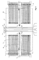
- Fig. 1 is a top view of a first embodiment of the device,
- Fig. 2 is a schematic sectional view along line II-II of Fig. 1,
- Fig. 3 is a top view of a second embodiment,
- Fig. 4 is a top view of a third embodiment,
- Fig. 5 is a block diagram of a first embodiment of the circuitry of the device,
- Fig. 6 illustrates the sensing signal ΔT, the monitoring signal TP, and the digitized value of the sensing signal as a function of mass flow with constant and non-constant Vref input, and
- Fig. 7 is a block diagram of a second embodiment of the circuitry of the device.
- The device of Figs. 1 and 2 is designed as a semiconductor chip based on a silicon substrate 1, even though another semiconductor or dielectric substrate could be used as well, such as a glass substrate. A recess or
opening 2 has been formed in substrate 1 by etching techniques and is spanned by a membrane 3. Aheater 4 extends over membrane 3. In the embodiment of Figs. 1 and 2,heater 4 is formed by threeparallel conductors outer conductors center conductor 4b (having double cross section) is in series to theconductors - Two sensing
thermopiles polysilicon bars first junction 9 on membrane 3. The polysilicon andmetal bars second junction 10, whichsecond junction 10 is not located on membrane 3, but over the bulk of substrate 1. - The basic principle of operation of such a device is e.g. described in
US 2003/0115952 . A flow along flow direction F causes the distribution of heat fromheater 4 to become asymmetric, which creates a difference of temperature at thefirst junctions 9 of the twothermopiles second junctions 10 remain at substantially constant temperatures due to the heat exchange through the thermally conducting substrate 1. Hence, the difference of the voltages from thethermopiles first junctions 9 upstream and downstream ofheater 4. This temperature difference ΔT is a measure of the mass flow of the fluid. - As can be seen in Figs. 1 and 2, two
additional monitoring thermocouples sensing thermopiles monitoring thermocouple thermocouples heater 4 than thefirst junctions 9 of thesensing thermopiles heater 4. The second ends of the metal bars 7' are e.g. connected to a polysilicon lead 13 at a second junction 10'. The second junctions 10' are, in the embodiment of Figs. 1 and 2, located over the bulk of substrate 1. - Each
monitoring thermocouple heater 4. The voltages from the monitoringthermocouples - An embodiment of the circuitry of the device is shown in Fig. 5. It comprises an A/D-
converter 16 for digitizing the sensing signal ΔT, aheater control 17 for controlling the current throughheater 4 and amicrocontroller 18 for processing the digitized sensing signal and controlling the device. Advantageously, the circuitry for all theelements - Basically, A/D-
converter 16 can be any type, such as a successive-approximation ADC, a delta-encoded ADC or a sigma-delta converter. All such converter designs require a reference voltage Vref and generate a digitized value of the input signal normalized by Vref. The term "normalized", in this context, is to be understood such that the output value for a given input voltage depends linearly on the reciprocal value 1/Vref. - Advantageously, A/D-
converter 16 is a sigma-delta converter, such as it is e.g. disclosed inDE 101 29 300 . The description of the section "A/D-Wandler" and its associated figure of that document are incorporated herein by reference. - As can be seen in Fig. 5, the monitoring signal TP is fed to the reference input of A/D-
converter 16 as a reference voltage Vref. The purpose of this measure is described below. -
Heater control 17 of the embodiment of Fig. 5 regulates the power dissipated byheater 4 to a constant value. Alternatively, it regulates the current throughheater 4 to a constant value. - The dependence of the temperature difference ΔT as a function of flow v is shown in the upper graph of Fig. 6. For zero flow, ΔT = 0. With increasing flow, ΔT will start to rise linearly. At larger flows, however, the temperature of heater 4 (and therefore the monitoring signal TP) will decrease substantially because of the cooling effect that the passing fluid has on
heater 4. Hence, for increasing flows v, the slope of the curve ΔT(v) will decrease as shown in the upper graph of Fig. 6. - If Vref of A/D-
converter 16 were constant, the digitized value from A/D converter 16 would follow the curve "Vref = const" of the lower graph of Fig. 6. As will be understood by those skilled in the art, this will cause a decrease of measurement resolution for larger mass flows v because the resolution of the A/D-converter does not change over its range of input voltages. - However, as mentioned above, Vref is not constant, but rather it is set to the monitoring signal TP. Hence, the resolution of the A/D-converter will be coarser when the heater temperature is high, while the resolution will be finer when the heater temperature is low. This leads to a linearization of the digitized signal at the output of A/D-
converter 16 as indicated by the curve "Vref = TP" in the bottom graph of Fig. 6. - Hence, using the monitoring signal TP as a reference voltage Vref allows to obtain a more constant digitization resolution over a wider range of mass flows, which in turn allows an increased accuracy of measurement and/or it allows to decrease the bit resolution of the A/D-converter.
- At the same time, since the digitized value has been normalized by Vref, is proportional to the ratio ΔT:TP. Therefore, variations of the Seeback coefficient or of other parameters of the used thermocouples tend to be compensated. Such variations can e.g. be observed when the overall temperature of the device changes, or when membrane 3 is subjected to stress.
- In view of this it will become apparent that the design of Fig. 1 has a further advantage: The monitoring
thermocouples sensing thermopiles membrane 2 will affect both thethermocouples thermopiles converter 16. - Fig. 7 shows an alternative circuit design for the flow sensor. It differs from the one of Fig. 6 in that the monitoring signal TP is used as an input to
heater control 17. In this embodiment,heater control 17 forms a control loop that controls the current throughheater 4 in such a way that the value of the monitoring signal TP remains constant. Since the monitoring signal TP substantially corresponds to the temperature difference between the bulk substrate 1 andheater 4, this embodiment keeps this temperature difference substantially constant. - In that case, sensing signal ΔT is substantially linear to mass flow v. Hence, a constant voltage could be used as reference voltage for A/D-converter Vref. However, in order to compensate for residual fluctuations of monitoring signal TP, it is still advantageous to use TP as reference voltage Vref.
- Fig. 3 shows an alternative design of the
monitoring thermocouples monitoring thermocouples heater 4 more quickly and more accurately. - A further embodiment of the
monitoring thermocouples monitoring thermopile 12 and are arranged in thegaps 20a, 20b between theconductors heater 4. Monitoring thermopile extends parallel to the longitudinal axis ofheater 4. - Monitoring
thermopile 12 consists of two sub-units, each of which is built as follows: Afirst bar 7a of a first material, namely metal, extends from a first end ofheater 4 to the center of the same. Asecond bar 8a of a second material, namely polysilicon, extends from ajunction 9a withfirst bar 7a to the second end ofheater 4, where it ends in ajunction 10a. Athird bar 7b of the first material is connected tojunction 10a and extends back to the center ofheater 4, where it ends in athird junction 9b. Afourth bar 8b of the second material extends fromjunction 9b to the first end ofheater 4. The same design is repeated by the sub-unit in thesecond gap 20b. Each sub-unit measures the difference between the temperature over bulk substrate 1 and the temperature at the center ofheater 4. The two-sub-units are connected in series via abridge 22 for adding their voltage. - The design of Fig. 4 has the advantage that the monitoring signal TP follows the temperature of
heater 4 more closely. In addition, heat conducting metal or polysilicon leads in thegaps 24 betweenheater 4 and thesensing thermopiles - In the embodiments described so far, membrane 3 forms a "measuring region" in contrast to the remaining "regular region" of the chip surface supported by bulk substrate 1. The measuring region has much lower heat conductance between the components located thereon than the regular region. At least part of each, the
heater 4, thesensing thermopiles recess 2 in the semiconductor chip. The membrane structure can either be formed by a membrane completely closing the opening or recess in the chip, or by a bridge or tongue extending over or into the opening or recess. - Instead of using a recess or
opening 2, the measuring region could also be located on top of a layer of material having low thermal conductivity, such as a nanoporous silicon oxide. - The embodiments shown so far comprise two sensing thermopiles arranged upstream and downstream from
heater 4. It must be noted, though, that a single thermopile can be used, which is e.g. located downstream from the heater, in particular if the device is designed to measure flow in one direction only, or which extends between junctions upstream and downstream of the heater. - Similarly, the sensing thermocouples of the above embodiments are arranged symmetrically in respect to the longitudinal axis of
heater 4. In particular if the device is designed to measure flow in one direction only, a non-symmetric design can be used as well. - Advantageously, a design of the thermocouples that is substantially symmetric to a line extending along flow direction F through the center of
heater 4 should be used. This allows to correct for asymmetries when positioning the device. For example, in the embodiment of Figs. 1 and 3, amonitoring thermocouple sensing thermopiles sensing thermopile - Even though, in the embodiments shown so far, most temperature sensors were thermopiles consisting of a plurality of thermocouples in series, it must be noted that some or all of them may be replaced by single thermocouples (or vice versa) depending on desired signal voltages and available space.
- In the embodiment of Figs. 5 and 7, the ratio ΔT:TP was calculated prior or during analog digital conversion. However, this ratio can also be calculated numerically in
microcontroller 18 if the monitoring value TP is digitized as well. - It must be noted that in the embodiments described above, each thermocouple used in the various thermopiles or alone consists of two conductors consisting of a first and a second material, respectively. Advantageously, the same materials are used for all thermocouples in order to profit from a shared Seeback coefficient. Advantageously, one material is a polysilicon and the other a metal, such as aluminum, both being materials conventionally used in integrated circuit technology. In addition, and again in order to have thermocouples with uniform properties, all conductors of the thermocouples should be manufactured from a the same two layers deposited on the substrate, e.g. one being a polysilicon layer and the other a metal layer.
Claims (16)
- A device for measuring the flow of a fluid comprising
a substrate (1),
a heater (4) arranged on said substrate (1),
at least one sensing thermocouple (7, 8) for generating a sensing signal (ΔT), which sensing thermocouple (7, 8) is arranged on said substrate (1), wherein a junction (9) of said sensing thermocouple (7, 8) closest to said heater (4) is arranged at a first distance from said heater (4),
a control circuit (18) adapted to measure a flow of the fluid over said heater (4) and said sensing thermocouple (7, 8) from a flow-dependent heating of said sensing thermocouple (7, 8) by said heater (4),
characterized by
at least one monitoring thermocouple (12a, 12b) for generating a monitoring signal (TP), which monitoring thermocouple (12a, 12b) is arranged on said substrate (1), wherein a junction (9', 9a, 9b) of said monitoring thermocouple (12a, 12b) closest to said heater (4) is arranged at a second distance from said heater (4), wherein said second distance is smaller than said first distance. - The device of claim 1 further comprising means (16, 18) for generating a signal proportional to a ratio of said sensing signal (ΔT) and said monitoring signal (TP).
- The device of any of the preceding claims comprising at least one first and at least one second sensing thermocouple (7, 8) for measuring a temperature difference between a location upstream and downstream from said heater (4), wherein said sensing signal (ΔT) is proportional to said temperature difference.
- The device of claim 3 comprising a first and a second monitoring thermocouple (12a, 12b) arranged on opposite sides of said heater (4), and in particular where the monitoring signal (TP) corresponds to a sum of the voltages from the first and the second monitoring thermocouple (12a, 12b).
- The device of any of the preceding claims wherein said substrate (1) is divided into a measuring region and a regular region, wherein a thermal conductance in said measuring region is lower than a thermal conductance in said regular region, and wherein said heater (4), said sensing thermocouple (7, 8) and said monitoring thermocouple (12a, 12b) are arranged at least partially on said measuring region.
- The device of the claims 3 and 5 wherein some junctions (10) of each of said first and second sensing thermocouples (7, 8) are arranged on said regular region.
- The device of any of the claims 5 or 6 wherein a first junction (9', 9a, 9b) of said monitoring thermocouple (12a, 12b) is arranged on said measuring region and a second junction (10', 10a, 10b) of said monitoring thermocouple (12a, 12b) is arranged on said regular region.
- The device of any of the claims 5 or 6 wherein a both junctions (9', 10') of said monitoring thermocouple (12a, 12b) are arranged on said measuring region.
- The device of any of the claims 5 to 8 comprising a hole or recess (2) in said substrate (1) and a membrane structure (3) extending over said hole or recess (2), wherein said measuring region is defined by said membrane structure (3).
- The device of any of the preceding claims further comprising a control loop (17) controlling a current through said heater (4) in order to keep said monitoring signal (TP) constant.
- The device of any of the preceding claims further comprising an analog/digital converter (16) for converting said sensing signal (ΔT), wherein said analog/digital converter (16) has a reference input and generates a digitized value of said sensing signal (ΔT) normalized by a signal (Vref) at said reference input, wherein said monitoring signal (TP) is applied to said reference input.
- The device of any of the preceding claims wherein said at least one sensing thermocouple (7, 8) extends parallel to said monitoring thermocouple (12a, 12b).
- The device of any of the preceding claims wherein said monitoring thermocouple (12a, 12b) or thermocouples is/are arranged symmetrically in respect to a longitudinal axis of said heater (4).
- The device of any of the preceding claims wherein said heater (4) comprises several conductors (4a, 4b, 4c) with at least one gap (20a, 20b) between said conductors (4a, 4b, 4c), wherein said monitoring thermocouple (12a, 12b) is arranged in said gap (20a, 20b).
- The device of any of the preceding claims having a plurality of monitoring thermocouples (12a, 12b) comprising
a first bar (7a) of a first material extending from a first end of said heater (4) to a center of said heater (4) and
a second bar (8a) of a second material connected at said center of said heater (4) to said first bar and extending to a second end of said heater (4),
and, in particular, further comprising
a third bar (7b) of said first material being connected to said second bar at said second end and extending to said center and
a fourth bar (8b) of said second material being connected to said third bar at said center and extending to said first end. - The device of any of the preceding claims wherein the junction (9', 9a, 9b) of said monitoring thermocouple (12a, 12b) closest to said heater (4) is adapted to measure a temperature of said heater (4).
Priority Applications (5)
| Application Number | Priority Date | Filing Date | Title |
|---|---|---|---|
| EP06006933A EP1840535B1 (en) | 2006-03-31 | 2006-03-31 | Flow sensor with thermocouples |
| DE602006019548T DE602006019548D1 (en) | 2006-03-31 | 2006-03-31 | Flow sensor with thermocouples |
| US11/729,025 US8011240B2 (en) | 2006-03-31 | 2007-03-27 | Flow sensor with thermocouples |
| JP2007094660A JP5112728B2 (en) | 2006-03-31 | 2007-03-30 | Flow sensor with thermocouple |
| CN2007101292365A CN101078641B (en) | 2006-03-31 | 2007-03-30 | Flow sensor with thermocouples |
Applications Claiming Priority (1)
| Application Number | Priority Date | Filing Date | Title |
|---|---|---|---|
| EP06006933A EP1840535B1 (en) | 2006-03-31 | 2006-03-31 | Flow sensor with thermocouples |
Publications (2)
| Publication Number | Publication Date |
|---|---|
| EP1840535A1 true EP1840535A1 (en) | 2007-10-03 |
| EP1840535B1 EP1840535B1 (en) | 2011-01-12 |
Family
ID=36992580
Family Applications (1)
| Application Number | Title | Priority Date | Filing Date |
|---|---|---|---|
| EP06006933A Expired - Lifetime EP1840535B1 (en) | 2006-03-31 | 2006-03-31 | Flow sensor with thermocouples |
Country Status (5)
| Country | Link |
|---|---|
| US (1) | US8011240B2 (en) |
| EP (1) | EP1840535B1 (en) |
| JP (1) | JP5112728B2 (en) |
| CN (1) | CN101078641B (en) |
| DE (1) | DE602006019548D1 (en) |
Cited By (17)
| Publication number | Priority date | Publication date | Assignee | Title |
|---|---|---|---|---|
| WO2010004484A1 (en) | 2008-07-08 | 2010-01-14 | Koninklijke Philips Electronics N.V. | Sensor and control unit for flow control and a method for controlled delivery of fluid |
| EP2172755A1 (en) | 2008-10-06 | 2010-04-07 | Sensirion AG | Infrared sensor with front side bandpass filter and vacuum cavity |
| EP2172754A1 (en) | 2008-10-06 | 2010-04-07 | Sensirion AG | Infrared sensor with back side infrared filter |
| EP2172753A1 (en) | 2008-10-06 | 2010-04-07 | Sensirion AG | A method for manufacturing infrared sensor on a wafer basis |
| EP2187182A1 (en) | 2008-11-12 | 2010-05-19 | Sensirion AG | Method for operating a flow sensor subjected to thermal and/or chemical treatments |
| EP2204555A1 (en) | 2009-01-02 | 2010-07-07 | Sensirion AG | Ammonia storage system |
| EP2224218A1 (en) | 2009-02-25 | 2010-09-01 | Sensirion AG | A sensor in a moulded package and a method for manufacturing the same |
| US8408050B2 (en) | 2008-10-09 | 2013-04-02 | Sensirion Ag | Method for measuring a fluid composition parameter by means of a flow sensor |
| DE102012001573A1 (en) * | 2012-01-18 | 2013-07-18 | Hydrometer Gmbh | Method for measuring a flow rate of a flowing gas |
| EP3118711A1 (en) | 2015-07-17 | 2017-01-18 | Sensirion AG | Inlet pressure perturbation insensitive mass flow controller |
| EP3392621A1 (en) | 2017-04-19 | 2018-10-24 | Sensirion AG | Membrane-based thermal flow sensor device |
| EP3404373A1 (en) | 2017-05-17 | 2018-11-21 | Sensirion AG | Flow sensor with thermocouples |
| EP3421947A1 (en) | 2017-06-30 | 2019-01-02 | Sensirion AG | Operation method for flow sensor device |
| EP3502687A1 (en) | 2017-12-20 | 2019-06-26 | Sensirion AG | Determination of gas parameters |
| EP3032227B1 (en) * | 2014-12-08 | 2020-10-21 | Sensirion AG | Flow sensor package |
| DE102022127043A1 (en) * | 2022-10-15 | 2024-04-18 | Sensirion Ag | Drift compensation for a sensor measuring the concentration of a substance in a fluid |
| CN122084053A (en) * | 2026-04-24 | 2026-05-26 | 山东大学 | A high-sensitivity MEMS flow sensor and its fabrication method |
Families Citing this family (21)
| Publication number | Priority date | Publication date | Assignee | Title |
|---|---|---|---|---|
| DE602006019688D1 (en) * | 2006-03-31 | 2011-03-03 | Sensirion Holding Ag | Flow sensor with flow-adaptable analog-to-digital converter |
| EP1965179B1 (en) * | 2007-02-28 | 2017-04-12 | Sensirion Holding AG | Flow detector device with self check |
| DE202007003027U1 (en) * | 2007-03-01 | 2007-06-21 | Sensirion Ag | Device for handling fluids with a channelled substrate has measuring substrate with integrated heater and temperature sensor both in thermal contact with channel and connected electrically to superposed system |
| WO2011089489A1 (en) * | 2010-01-20 | 2011-07-28 | Koninklijke Philips Electronics N.V. | Aerosol delivery system with temperature-based aerosol detector |
| WO2011089490A1 (en) * | 2010-01-20 | 2011-07-28 | Koninklijke Philips Electronics N.V. | Flow sensor and aerosol delivery device |
| EP2762864B1 (en) | 2013-01-31 | 2018-08-08 | Sensirion AG | Membrane-based sensor device and method for manufacturing the same |
| JP5981397B2 (en) * | 2013-07-11 | 2016-08-31 | 日立オートモティブシステムズ株式会社 | Thermal flow meter |
| US9612146B2 (en) | 2014-02-07 | 2017-04-04 | Honeywell International, Inc. | Airflow sensor with dust reduction |
| CN105590925B (en) * | 2014-10-22 | 2019-03-01 | 日月光半导体制造股份有限公司 | Semiconductor package structure and manufacturing method thereof |
| EP3029429B1 (en) * | 2014-12-04 | 2020-10-07 | Sensirion AG | Determination of fluid composition in a mass flow controller |
| EP2930475B1 (en) * | 2014-12-22 | 2017-11-15 | Sensirion AG | Flow sensor arrangement |
| US10759326B2 (en) * | 2016-05-27 | 2020-09-01 | Carrier Corporation | Method for determining reduced airflow in transport refrigeration system |
| EP3301441B1 (en) | 2016-09-30 | 2018-11-07 | Siemens Aktiengesellschaft | Thermal conductivity detector for gas mixtures having at least three components |
| FR3065281B1 (en) * | 2017-04-18 | 2019-06-14 | Centre National De La Recherche Scientifique | DEVICE FOR MEASURING SPEED OR GAS FLOW |
| CA3087632C (en) | 2018-01-05 | 2025-05-20 | Hahn-Schickard-Gesellschaft Fuer Angewandte Forschung E.V. | Gas sensor and method for operating the gas sensor |
| EP4141430B1 (en) | 2018-01-05 | 2025-06-18 | Hahn-Schickard-Gesellschaft für angewandte Forschung e. V. | Evaluation arrangement for a thermal gas sensor, method and computer program |
| US10775217B1 (en) | 2019-04-19 | 2020-09-15 | Honeywell International Inc. | Thermophile-based flow sensing device |
| JP7112373B2 (en) * | 2019-05-24 | 2022-08-03 | Mmiセミコンダクター株式会社 | flow sensor chip |
| JP7258800B2 (en) | 2020-03-02 | 2023-04-17 | Mmiセミコンダクター株式会社 | Thermopile type sensor |
| US12044561B2 (en) * | 2020-11-06 | 2024-07-23 | Honeywell International Inc. | Flow sensing device |
| EP4521102A1 (en) | 2021-12-17 | 2025-03-12 | Sensirion AG | Thermal sensor device and method for determining concentration of a target gas in a gas sample |
Citations (5)
| Publication number | Priority date | Publication date | Assignee | Title |
|---|---|---|---|---|
| US5830372A (en) * | 1994-05-25 | 1998-11-03 | Siemens Aktiengesellschaft | Thermal sensor/actuator in semiconductor material |
| EP1065475A2 (en) * | 1999-05-31 | 2001-01-03 | Sensirion AG | Method of measuring a gas flow |
| EP1094306A1 (en) * | 1999-04-27 | 2001-04-25 | Yazaki Corporation | Thermal flow sensor, method and apparatus for identifying fluid, flow sensor, and method and apparatus for flow measurement |
| US20020007674A1 (en) * | 1996-06-26 | 2002-01-24 | Leung Albert M. | Accelerometer without proof mass |
| EP1477781A1 (en) * | 2003-05-13 | 2004-11-17 | Berkin B.V. | Mass flowmeter |
Family Cites Families (41)
| Publication number | Priority date | Publication date | Assignee | Title |
|---|---|---|---|---|
| US3042786A (en) * | 1958-08-14 | 1962-07-03 | American Brake Shoe Co | Electrical heating apparatus |
| JPS53131326A (en) | 1977-04-22 | 1978-11-16 | Hitachi Ltd | Control device of internal combustn engine |
| NL177629C (en) | 1979-07-09 | 1985-10-16 | Brooks Instr Bv | DIRECTIONAL SENSITIVE FLOW SPEEDOMETER. |
| US4651564A (en) * | 1982-09-30 | 1987-03-24 | Honeywell Inc. | Semiconductor device |
| JPS604815A (en) | 1983-06-23 | 1985-01-11 | Nippon Soken Inc | Flow rate measuring apparatus |
| US4672997A (en) * | 1984-10-29 | 1987-06-16 | Btu Engineering Corporation | Modular, self-diagnostic mass-flow controller and system |
| US4884443A (en) | 1987-12-23 | 1989-12-05 | Siemens-Bendix Automotive Electronics L. P. | Control and detection circuitry for mass airflow sensors |
| US4784721A (en) | 1988-02-22 | 1988-11-15 | Honeywell Inc. | Integrated thin-film diaphragm; backside etch |
| JP2666163B2 (en) | 1991-12-04 | 1997-10-22 | 山武ハネウエル株式会社 | Temperature characteristic correction method for flow velocity sensor |
| US5233868A (en) | 1992-04-13 | 1993-08-10 | Coats Montgomery R | Non-intrusive mass flow measuring apparatus and method |
| JP3175887B2 (en) | 1992-10-27 | 2001-06-11 | 株式会社半導体エネルギー研究所 | measuring device |
| US5288147A (en) * | 1992-11-09 | 1994-02-22 | Ta Instruments, Inc. | Thermopile differential thermal analysis sensor |
| US5393351A (en) * | 1993-01-13 | 1995-02-28 | The United States Of America As Represented By The Secretary Of Commerce | Multilayer film multijunction thermal converters |
| EP0698786A1 (en) | 1994-08-23 | 1996-02-28 | RICOH SEIKI COMPANY, Ltd. | Atmosphere measuring device and flow sensor |
| NL1000454C2 (en) * | 1995-05-30 | 1996-12-03 | Mierij Meteo Bv | Device for determining the direction and speed of an air flow. |
| DE19527861B4 (en) | 1995-07-29 | 2010-09-30 | Robert Bosch Gmbh | Mass flow sensor and method of manufacture |
| JPH0972763A (en) | 1995-09-07 | 1997-03-18 | Ricoh Co Ltd | Micro sensor |
| US5763775A (en) | 1996-03-13 | 1998-06-09 | Ricoh Company, Ltd. | Flow sensor having first and second temperature detecting portions for accurate measuring of a flow rate and a manufacturing method thereof |
| JP3366818B2 (en) | 1997-01-16 | 2003-01-14 | 株式会社日立製作所 | Thermal air flow meter |
| DE59701822D1 (en) | 1997-02-14 | 2000-07-06 | Fraunhofer Ges Forschung | FLOW SENSOR COMPONENT |
| JP3333712B2 (en) | 1997-06-19 | 2002-10-15 | 三菱電機株式会社 | Flow rate detecting element and flow rate sensor using the same |
| US6378365B1 (en) * | 1997-08-22 | 2002-04-30 | Eulite Laboratories Inc. | Micromachined thermal flowmeter having heating element disposed in a silicon island |
| US6545334B2 (en) * | 1997-12-19 | 2003-04-08 | Imec Vzw | Device and a method for thermal sensing |
| NL1008665C1 (en) * | 1998-03-20 | 1999-09-21 | Berkin Bv | Medium flow meter. |
| JP3433124B2 (en) | 1998-12-15 | 2003-08-04 | 株式会社日立製作所 | Thermal air flow sensor |
| JP2002533663A (en) | 1998-12-22 | 2002-10-08 | ゼンジリオン アクチエンゲゼルシャフト | Method and sensor for measuring mass flow |
| JP3470881B2 (en) * | 1999-04-19 | 2003-11-25 | 矢崎総業株式会社 | Micro flow sensor |
| DE10082701D2 (en) | 1999-09-09 | 2002-08-14 | Sensirion Ag Zuerich | Method and device for precision mass flow measurement |
| CH695166A5 (en) | 2000-04-25 | 2005-12-30 | Sensirion Ag | Method and apparatus for measuring the flow of a liquid. |
| WO2001088486A1 (en) | 2000-05-19 | 2001-11-22 | Mitsubishi Denki Kabushiki Kaisha | Heat-sensitive type flow rate detecting element and holder therefor |
| CH694474A5 (en) | 2000-06-23 | 2005-01-31 | Sensirion Ag | Gas meter and use of the gas meter. |
| JP2002048615A (en) * | 2000-08-02 | 2002-02-15 | Tokyo Gas Co Ltd | Flow meter using heat flow sensor |
| JP3658321B2 (en) * | 2000-12-28 | 2005-06-08 | オムロン株式会社 | Flow sensor and manufacturing method thereof |
| US6631638B2 (en) * | 2001-01-30 | 2003-10-14 | Rosemount Aerospace Inc. | Fluid flow sensor |
| GR1004106B (en) * | 2002-01-24 | 2003-01-13 | Εκεφε "Δημοκριτος" Ινστιτουτο Μικροηλεκτρονικης | Low power silicon thermal sensors and microfluidic devices based on the use of porous silicon sealed air cavity technology or microchannel technology |
| EP1351039A1 (en) | 2002-04-03 | 2003-10-08 | Sensirion AG | Flow sensor and method for producing the same |
| EP1396705B1 (en) | 2002-08-27 | 2016-12-21 | Sensirion Holding AG | Flow detector with through-holes and and process for making the same |
| JP3945385B2 (en) * | 2002-11-15 | 2007-07-18 | オムロン株式会社 | Flow sensor and flow measurement method |
| JP3718198B2 (en) * | 2003-02-26 | 2005-11-16 | 株式会社日立製作所 | Flow sensor |
| CN1297802C (en) * | 2004-02-12 | 2007-01-31 | 李韫言 | All silicon integrated flow sensor and method for manufacturing the same |
| DE602006019688D1 (en) * | 2006-03-31 | 2011-03-03 | Sensirion Holding Ag | Flow sensor with flow-adaptable analog-to-digital converter |
-
2006
- 2006-03-31 EP EP06006933A patent/EP1840535B1/en not_active Expired - Lifetime
- 2006-03-31 DE DE602006019548T patent/DE602006019548D1/en not_active Expired - Lifetime
-
2007
- 2007-03-27 US US11/729,025 patent/US8011240B2/en active Active
- 2007-03-30 CN CN2007101292365A patent/CN101078641B/en active Active
- 2007-03-30 JP JP2007094660A patent/JP5112728B2/en active Active
Patent Citations (5)
| Publication number | Priority date | Publication date | Assignee | Title |
|---|---|---|---|---|
| US5830372A (en) * | 1994-05-25 | 1998-11-03 | Siemens Aktiengesellschaft | Thermal sensor/actuator in semiconductor material |
| US20020007674A1 (en) * | 1996-06-26 | 2002-01-24 | Leung Albert M. | Accelerometer without proof mass |
| EP1094306A1 (en) * | 1999-04-27 | 2001-04-25 | Yazaki Corporation | Thermal flow sensor, method and apparatus for identifying fluid, flow sensor, and method and apparatus for flow measurement |
| EP1065475A2 (en) * | 1999-05-31 | 2001-01-03 | Sensirion AG | Method of measuring a gas flow |
| EP1477781A1 (en) * | 2003-05-13 | 2004-11-17 | Berkin B.V. | Mass flowmeter |
Non-Patent Citations (1)
| Title |
|---|
| MALCOVATI P ET AL: "COMBINED AIR HUMIDITY AND FLOW CMOS MICROSENSOR WITH ON-CHIP 15 BITSIGMA-DELTA A/D INTERFACE", 1995 SYMPOSIUM ON VLSI CIRCUITS. KYOTO, JUNE 8 - 10, 1995, SYMPOSIUM ON VLSI CIRCUITS, NEW YORK, IEEE, US, 8 June 1995 (1995-06-08), pages 45 - 46, XP000557797, ISBN: 0-7803-2600-8 * |
Cited By (24)
| Publication number | Priority date | Publication date | Assignee | Title |
|---|---|---|---|---|
| RU2509984C2 (en) * | 2008-07-08 | 2014-03-20 | Конинклейке Филипс Электроникс Н.В. | Sensor and unit of control for flow control, and also method of controlled liquid delivery |
| WO2010004484A1 (en) | 2008-07-08 | 2010-01-14 | Koninklijke Philips Electronics N.V. | Sensor and control unit for flow control and a method for controlled delivery of fluid |
| US8784367B2 (en) | 2008-07-08 | 2014-07-22 | Koninklijke Philips N.V | Sensor and control unit for flow control and a method for controlled delivery of fluid |
| EP2172753A1 (en) | 2008-10-06 | 2010-04-07 | Sensirion AG | A method for manufacturing infrared sensor on a wafer basis |
| EP2172754A1 (en) | 2008-10-06 | 2010-04-07 | Sensirion AG | Infrared sensor with back side infrared filter |
| EP2172755A1 (en) | 2008-10-06 | 2010-04-07 | Sensirion AG | Infrared sensor with front side bandpass filter and vacuum cavity |
| US8408050B2 (en) | 2008-10-09 | 2013-04-02 | Sensirion Ag | Method for measuring a fluid composition parameter by means of a flow sensor |
| EP2187182A1 (en) | 2008-11-12 | 2010-05-19 | Sensirion AG | Method for operating a flow sensor subjected to thermal and/or chemical treatments |
| EP2204555A1 (en) | 2009-01-02 | 2010-07-07 | Sensirion AG | Ammonia storage system |
| US8771598B2 (en) | 2009-01-02 | 2014-07-08 | Sensirion Ag | Ammonia storage system |
| EP2224218A1 (en) | 2009-02-25 | 2010-09-01 | Sensirion AG | A sensor in a moulded package and a method for manufacturing the same |
| DE102012001573A1 (en) * | 2012-01-18 | 2013-07-18 | Hydrometer Gmbh | Method for measuring a flow rate of a flowing gas |
| DE102012001573B4 (en) | 2012-01-18 | 2018-10-11 | Diehl Metering Gmbh | Method for measuring a flow rate of a flowing gas and flow meter |
| EP3032227B1 (en) * | 2014-12-08 | 2020-10-21 | Sensirion AG | Flow sensor package |
| EP3118711A1 (en) | 2015-07-17 | 2017-01-18 | Sensirion AG | Inlet pressure perturbation insensitive mass flow controller |
| US10345829B2 (en) | 2015-07-17 | 2019-07-09 | Sensirion Ag | Inlet pressure perturbation insensitive mass flow controller |
| EP3392621A1 (en) | 2017-04-19 | 2018-10-24 | Sensirion AG | Membrane-based thermal flow sensor device |
| EP3404373A1 (en) | 2017-05-17 | 2018-11-21 | Sensirion AG | Flow sensor with thermocouples |
| EP3421947A1 (en) | 2017-06-30 | 2019-01-02 | Sensirion AG | Operation method for flow sensor device |
| US10942139B2 (en) | 2017-06-30 | 2021-03-09 | Sensirion Ag | Operation method for flow sensor device |
| EP3502687A1 (en) | 2017-12-20 | 2019-06-26 | Sensirion AG | Determination of gas parameters |
| DE102022127043A1 (en) * | 2022-10-15 | 2024-04-18 | Sensirion Ag | Drift compensation for a sensor measuring the concentration of a substance in a fluid |
| DE102022127043B4 (en) | 2022-10-15 | 2024-05-23 | Sensirion Ag | Drift compensation for a sensor measuring the concentration of a substance in a fluid |
| CN122084053A (en) * | 2026-04-24 | 2026-05-26 | 山东大学 | A high-sensitivity MEMS flow sensor and its fabrication method |
Also Published As
| Publication number | Publication date |
|---|---|
| US8011240B2 (en) | 2011-09-06 |
| JP5112728B2 (en) | 2013-01-09 |
| JP2007279036A (en) | 2007-10-25 |
| DE602006019548D1 (en) | 2011-02-24 |
| US20070241093A1 (en) | 2007-10-18 |
| EP1840535B1 (en) | 2011-01-12 |
| CN101078641B (en) | 2011-06-29 |
| CN101078641A (en) | 2007-11-28 |
Similar Documents
| Publication | Publication Date | Title |
|---|---|---|
| EP1840535B1 (en) | Flow sensor with thermocouples | |
| US7490511B2 (en) | Flow sensor with flow-adaptable analog-digital-converter | |
| JP2007282218A5 (en) | ||
| EP3404373B1 (en) | Flow sensor with thermocouples | |
| JP3658321B2 (en) | Flow sensor and manufacturing method thereof | |
| JP5210491B2 (en) | Thermal flow sensor | |
| US6508585B2 (en) | Differential scanning calorimeter | |
| US7617724B2 (en) | Thermal mass flow meter having a heater and paired temperature sensor chips separately formed and mounted on the flow pipe | |
| US9983233B2 (en) | Current sensor | |
| US10094691B2 (en) | Flow sensor arrangement | |
| EP1541974B1 (en) | Heating resistor type flow-measuring device | |
| JPH10197309A (en) | Measuring element for thermal air flow meter and thermal air flow meter | |
| EP4198504B1 (en) | Thermal sensor device and method for determining concentration of a target gas in a gas sample | |
| US7481574B2 (en) | Thermal flow rate sensor supplying digital output | |
| US6338271B1 (en) | Device and process for measuring the velocity of flow of a fluid | |
| EP1873499A1 (en) | Thermal flow sensor for high flow velocities | |
| JP5319744B2 (en) | Thermal flow sensor | |
| JPH11125550A (en) | Sensor | |
| JP2022129947A (en) | thermal sensor | |
| WO2024240546A1 (en) | Compensation of variations of ambient temperature in a thermal sensor device | |
| JP2002310762A (en) | Flow sensor |
Legal Events
| Date | Code | Title | Description |
|---|---|---|---|
| PUAI | Public reference made under article 153(3) epc to a published international application that has entered the european phase |
Free format text: ORIGINAL CODE: 0009012 |
|
| AK | Designated contracting states |
Kind code of ref document: A1 Designated state(s): AT BE BG CH CY CZ DE DK EE ES FI FR GB GR HU IE IS IT LI LT LU LV MC NL PL PT RO SE SI SK TR |
|
| AX | Request for extension of the european patent |
Extension state: AL BA HR MK YU |
|
| 17P | Request for examination filed |
Effective date: 20080315 |
|
| AKX | Designation fees paid |
Designated state(s): CH DE GB LI |
|
| RAP1 | Party data changed (applicant data changed or rights of an application transferred) |
Owner name: SENSIRION HOLDING AG |
|
| GRAP | Despatch of communication of intention to grant a patent |
Free format text: ORIGINAL CODE: EPIDOSNIGR1 |
|
| GRAS | Grant fee paid |
Free format text: ORIGINAL CODE: EPIDOSNIGR3 |
|
| GRAA | (expected) grant |
Free format text: ORIGINAL CODE: 0009210 |
|
| AK | Designated contracting states |
Kind code of ref document: B1 Designated state(s): CH DE GB LI |
|
| REG | Reference to a national code |
Ref country code: GB Ref legal event code: FG4D |
|
| REG | Reference to a national code |
Ref country code: CH Ref legal event code: EP Ref country code: CH Ref legal event code: NV Representative=s name: E. BLUM & CO. AG PATENT- UND MARKENANWAELTE VSP |
|
| REF | Corresponds to: |
Ref document number: 602006019548 Country of ref document: DE Date of ref document: 20110224 Kind code of ref document: P |
|
| REG | Reference to a national code |
Ref country code: DE Ref legal event code: R096 Ref document number: 602006019548 Country of ref document: DE Effective date: 20110224 |
|
| PLBE | No opposition filed within time limit |
Free format text: ORIGINAL CODE: 0009261 |
|
| STAA | Information on the status of an ep patent application or granted ep patent |
Free format text: STATUS: NO OPPOSITION FILED WITHIN TIME LIMIT |
|
| 26N | No opposition filed |
Effective date: 20111013 |
|
| REG | Reference to a national code |
Ref country code: DE Ref legal event code: R097 Ref document number: 602006019548 Country of ref document: DE Effective date: 20111013 |
|
| P01 | Opt-out of the competence of the unified patent court (upc) registered |
Effective date: 20230527 |
|
| PGFP | Annual fee paid to national office [announced via postgrant information from national office to epo] |
Ref country code: DE Payment date: 20250319 Year of fee payment: 20 |
|
| PGFP | Annual fee paid to national office [announced via postgrant information from national office to epo] |
Ref country code: GB Payment date: 20250324 Year of fee payment: 20 |
|
| PGFP | Annual fee paid to national office [announced via postgrant information from national office to epo] |
Ref country code: CH Payment date: 20250401 Year of fee payment: 20 |
|
| REG | Reference to a national code |
Ref country code: CH Ref legal event code: H14 Free format text: ST27 STATUS EVENT CODE: U-0-0-H10-H14 (AS PROVIDED BY THE NATIONAL OFFICE) Effective date: 20260331 Ref country code: DE Ref legal event code: R071 Ref document number: 602006019548 Country of ref document: DE |
|
| REG | Reference to a national code |
Ref country code: GB Ref legal event code: PE20 Expiry date: 20260330 |