EP3502475A2 - A reciprocating compressor and manufacturing method - Google Patents
A reciprocating compressor and manufacturing method Download PDFInfo
- Publication number
- EP3502475A2 EP3502475A2 EP18212273.9A EP18212273A EP3502475A2 EP 3502475 A2 EP3502475 A2 EP 3502475A2 EP 18212273 A EP18212273 A EP 18212273A EP 3502475 A2 EP3502475 A2 EP 3502475A2
- Authority
- EP
- European Patent Office
- Prior art keywords
- gas
- valve seat
- suction
- delivery
- compressor
- Prior art date
- Legal status (The legal status is an assumption and is not a legal conclusion. Google has not performed a legal analysis and makes no representation as to the accuracy of the status listed.)
- Granted
Links
Images


Classifications
-
- F—MECHANICAL ENGINEERING; LIGHTING; HEATING; WEAPONS; BLASTING
- F04—POSITIVE - DISPLACEMENT MACHINES FOR LIQUIDS; PUMPS FOR LIQUIDS OR ELASTIC FLUIDS
- F04B—POSITIVE-DISPLACEMENT MACHINES FOR LIQUIDS; PUMPS
- F04B39/00—Component parts, details, or accessories, of pumps or pumping systems specially adapted for elastic fluids, not otherwise provided for in, or of interest apart from, groups F04B25/00 - F04B37/00
- F04B39/12—Casings; Cylinders; Cylinder heads; Fluid connections
- F04B39/122—Cylinder block
-
- F—MECHANICAL ENGINEERING; LIGHTING; HEATING; WEAPONS; BLASTING
- F04—POSITIVE - DISPLACEMENT MACHINES FOR LIQUIDS; PUMPS FOR LIQUIDS OR ELASTIC FLUIDS
- F04B—POSITIVE-DISPLACEMENT MACHINES FOR LIQUIDS; PUMPS
- F04B39/00—Component parts, details, or accessories, of pumps or pumping systems specially adapted for elastic fluids, not otherwise provided for in, or of interest apart from, groups F04B25/00 - F04B37/00
- F04B39/06—Cooling; Heating; Prevention of freezing
- F04B39/064—Cooling by a cooling jacket in the pump casing
-
- F—MECHANICAL ENGINEERING; LIGHTING; HEATING; WEAPONS; BLASTING
- F04—POSITIVE - DISPLACEMENT MACHINES FOR LIQUIDS; PUMPS FOR LIQUIDS OR ELASTIC FLUIDS
- F04B—POSITIVE-DISPLACEMENT MACHINES FOR LIQUIDS; PUMPS
- F04B39/00—Component parts, details, or accessories, of pumps or pumping systems specially adapted for elastic fluids, not otherwise provided for in, or of interest apart from, groups F04B25/00 - F04B37/00
- F04B39/12—Casings; Cylinders; Cylinder heads; Fluid connections
- F04B39/123—Fluid connections
-
- F—MECHANICAL ENGINEERING; LIGHTING; HEATING; WEAPONS; BLASTING
- F04—POSITIVE - DISPLACEMENT MACHINES FOR LIQUIDS; PUMPS FOR LIQUIDS OR ELASTIC FLUIDS
- F04B—POSITIVE-DISPLACEMENT MACHINES FOR LIQUIDS; PUMPS
- F04B39/00—Component parts, details, or accessories, of pumps or pumping systems specially adapted for elastic fluids, not otherwise provided for in, or of interest apart from, groups F04B25/00 - F04B37/00
- F04B39/0027—Pulsation and noise damping means
- F04B39/0055—Pulsation and noise damping means with a special shape of fluid passage, e.g. bends, throttles, diameter changes, pipes
- F04B39/0072—Pulsation and noise damping means with a special shape of fluid passage, e.g. bends, throttles, diameter changes, pipes characterised by assembly or mounting
-
- F—MECHANICAL ENGINEERING; LIGHTING; HEATING; WEAPONS; BLASTING
- F04—POSITIVE - DISPLACEMENT MACHINES FOR LIQUIDS; PUMPS FOR LIQUIDS OR ELASTIC FLUIDS
- F04B—POSITIVE-DISPLACEMENT MACHINES FOR LIQUIDS; PUMPS
- F04B39/00—Component parts, details, or accessories, of pumps or pumping systems specially adapted for elastic fluids, not otherwise provided for in, or of interest apart from, groups F04B25/00 - F04B37/00
- F04B39/10—Adaptations or arrangements of distribution members
Definitions
- the subject matter disclosed herein generally relates to compressors and more specifically to reciprocating compressors.
- embodiments of the present disclosure concern double-acting reciprocating compressors.
- Reciprocating compressors are used in several industrial fields for compressing a gas, in particular when relatively small gas flow rates require to be compressed with a high compression ratio.
- a reciprocating compressor comprises a compressor cylinder forming a cylinder chamber therein.
- a piston is arranged in the cylinder chamber and is driven into reciprocating motion by a prime mover, such as an electric motor, a turbine or a reciprocating internal or external combustion engine, such as a Stirling engine.
- a crankshaft and a connecting rod mechanism converts the rotary motion of a motor shaft into reciprocating motion of the piston.
- the connecting rod is usually drivingly coupled to the piston through a cross-head and a piston rod.
- a valve arrangement provides for gas delivery into the cylinder chamber and gas discharge from the cylinder chamber.
- the piston divides the cylinder chamber into a first compression chamber and a second compression chamber. At least one suction valve and one delivery valve are fluidly coupled to the first compression chamber, and at least a further suction valve and a further delivery valve are fluidly coupled to the second compression chamber.
- the reciprocating motion of the piston in the cylinder chamber causes gas to be sucked in one of the compression chambers through the respective suction valve, while gas is compressed in the other compression chamber and discharged through the respective delivery valve, when a delivery pressure is achieved at which the delivery valve is opened.
- Suction valves and delivery valves are usually automatic valves, which automatically open and close in response to a pressure differential thereacross.
- the suction valves are fluidly coupled to an inlet plenum, which feeds gas at a lower pressure to the cylinder chamber.
- the delivery valves are in turn fluidly coupled to a discharge plenum, which collects gas at a higher pressure from the cylinder chamber.
- Fig.1 illustrates a double-acting reciprocating compressor 100 of the current art.
- the compressor 100 comprises a compressor head 101, a compressor frame 102 and a distance piece 103, which connects the compressor head 101 to the compressor frame 102.
- a crankshaft 104 is arranged in the compressor frame 102.
- the crankshaft 104 rotates around a rotation axis 106.
- a prime mover not shown, drives the crankshaft 104 into rotation.
- a connecting rod 108 transmits the motion from the crankshaft 104 to a crosshead 110, which moves reciprocatingly in a crosshead guide 112.
- a piston rod 114 connects the crosshead 110 to a piston 116, which is adapted to reciprocatingly slide in a chamber 118 of a compressor cylinder 120.
- the piston 116 divides the chamber 118 in a first compression chamber and a second compression chamber.
- the first and second compression chambers can be a head-end chamber 118A, and a crank-end chamber 118B.
- a process gas is selectively sucked into each one of said head-end and crank-end chambers 118A, 118B at a lower pressure (suction pressure), compressed and discharged at a higher pressure (delivery pressure).
- Said head-end chamber 118A and crank-end chamber 118B are provided each with at least one suction valve and one delivery valve. The suction, compression and discharge process is performed alternatively in the two chambers, i.e. when gas is sucked into one of the head-end chamber 118A and crank-end chamber 118B, gas in the other of said head-end chamber 118A and crank-end chamber 118B is compressed and discharged.
- Suction valves 122 of both crank-end chamber 118B and head-end chamber 118A are fluidly coupled to an inlet plenum 126, which is in turn fluidly coupled to a gas source 128.
- Delivery valves 124 of both crank-end chamber 118B and head-end chamber 118A are fluidly coupled to a discharge plenum 130, which is in turn fluidly coupled to a gas output 134.
- the inlet plenum 126 and the discharge plenum 130 are both formed in a barrel 132, which in turn forms a cylindrical side wall of the chamber 118.
- the gaseous flow through the inlet plenum 126 and the discharge plenum 130 and respective suction valves and delivery valves is complex and involves sharp bends due to the position of the valves in respective valve seats formed in the barrel 132. Specifically, gas enters the valve seats in a direction orthogonal to the axial direction of the valves, such that the gas flow turns by 90° when flowing from the inlet plenum into the suction valves and when flowing from the delivery valves into the discharge plenum.
- Cooling ducts 136 are further provided in the barrel 132.
- the shape of the inlet plenum and discharge plenum is restricted by the structure of the barrel. Mechanical constraints result in suboptimal fluid-dynamic design of the gas inlet and discharge plenums, which in turn causes fluid-dynamic losses and reduction of the overall efficiency of the compressor.
- cooling of the compressor head is inefficient and manufacturing of the cooling ducts is rendered complicated by the combined presence of valve seats, plenums and cooling arrangements in the barrel.
- GB1367164 discloses a double acting reciprocating compressor, wherein both the crank-end chamber and the head-end chamber of the compressor are provided with multiple suction valves and discharge valves.
- the suction valves connecting the low-pressure gas source to the respective chamber are connected to one another by a suction plenum which surrounds annularly the compressor barrel.
- the discharge valves connecting the high-pressure gas source to the respective chamber of the compressor are fluidly coupled to one another by a discharge plenum which annularly surrounds the compressor barrel.
- CN104747405 discloses a double-acting reciprocating compressor, wherein each one of the crank-end chamber and head-end chamber of the compressor is provided with two suction valves and two discharge valves, respectively.
- the pair of suction valves associated to the crank-end chamber are fluidly coupled to a respective suction plenum.
- the two plenums connected to the suction valves of the head-end chamber and crank-end chamber are in turn coupled to a suction duct.
- the two plenums connected to the discharge valves of the head-end chamber and crank-end chamber are in turn coupled to a discharge duct.
- the present disclosure concerns a manufacturing method for manufacturing a cylinder for a reciprocating compressor.
- the method comprises a step of manufacturing a compressor barrel comprised of a cylinder chamber, a first suction valve seat, fluidly coupled to the cylinder chamber through a respective first gas suction port; and a first delivery valve seat, fluidly coupled to the cylinder chamber through a respective first gas delivery port.
- the method further comprises the step of manufacturing by additive manufacturing a gas inlet plenum and further manufacturing by additive manufacturing a gas discharge plenum, separately from the compressor barrel.
- the gas inlet plenum and the gas discharge plenum can be attached around the compressor barrel in fluid communication with the gas suction port and the gas delivery port.
- the gas inlet plenum and the gas discharge plenum can thus be designed according to optimization criteria, to minimize the gas pressure losses along the gas path, without being subjected to mechanical constraints imposed by the shape of the compressor barrel.
- a manufacturing method for manufacturing a cylinder for a reciprocating compressor comprises the following steps:
- a reciprocating compressor comprising a compressor barrel with a cylinder chamber therein and a piston, adapted for reciprocatingly sliding in the cylinder chamber.
- the compressor further comprises a first suction valve fluidly coupled to the cylinder chamber and a first delivery valve fluidly coupled to the cylinder chamber.
- the compressor comprises a gas inlet plenum fluidly coupled to the first suction valve and a gas discharge plenum fluidly coupled to the first delivery valve.
- the gas inlet plenum and the gas discharge plenum are produced by additive manufacturing and are mechanically connected to the compressor barrel and external thereto.
- the exemplary reciprocating compressors disclosed herein alleviate or solve the drawbacks and limitations of the prior art by separating the gas inlet plenum and gas discharge plenum from the compressor barrel.
- the design of both the gas inlet plenum and the gas discharge plenum can thus be optimized from a fluid-dynamic and acoustic perspective, since less mechanical constraints are present.
- the shape of the inlet plenum and discharge plenum do not have to conform to the shape of the barrel, the cooling ducts and valve seats housed therein.
- the orientation of the inlet plenum and discharge plenum with respect to the position of the suction valves and delivery valves can be optimized. More space is available in the wall of the barrel to accommodate the valve seats and the cooling ducts. Also the shape of the cooling ducts can be ameliorated from the point of view of heat exchange efficiency, as well as from the point of view of machining.
- the barrel can be more easily manufactured and less expensive production techniques, rather than iron or steel casting, can be used.
- the barrel can be manufactured by forging or centrifugal casting, which makes the overall manufacturing process quicker, less expensive and less prone to generate scraps.
- gas inlet plenum and gas discharge plenum are produced by additive manufacturing, optimal design can be achieved, which result in reduction of fluid-dynamic losses in the inlet and discharge gas flows.
- compressor structure and the manufacturing processes disclosed herein can be beneficial also for the production of single-acting reciprocating compressors, they are particularly beneficial for the production of double-acting reciprocating compressors, where the shape of the gas inlet plenum and gas discharge plenum is particularly complex due to the higher number of suction valves and delivery valves provided at both ends of the compressor barrel.
- a double-acting reciprocating compressor comprises a cylinder comprised of a compressor barrel and a cylinder chamber formed in the barrel.
- the cylinder chamber is divided in a so-called head-end chamber and a so-called crank-end chamber by a piston, arranged for reciprocatingly sliding therein.
- the head-end chamber is fluidly coupled to a first suction valve through a first gas suction port and to a first delivery valve through a first gas delivery port.
- the crank-end chamber is fluidly coupled to a second suction valve through a second gas suction port and to a second delivery valve through a second gas delivery port.
- the double-acting reciprocating compressor is adapted to suck gas in one of the crank-end chamber and head-end chamber through the respective suction valve, while gas is compressed in the other of the crank-end chamber and head-end chamber and finally delivered through the respective delivery valve.
- Each crank-end chamber and head-end chamber can be fluidly coupled to more than one suction valve and one delivery valve.
- two respective suction valves and two respective delivery valves can be fluidly coupled to each one of said head-end chamber and crank-end chamber, to maximize gas flow and minimize head losses.
- All suction valves can be fluidly coupled to a single gas inlet plenum. All delivery valves can be fluidly coupled to a single gas discharge plenum.
- each suction valve and delivery valve is fluidly coupled to a central portion or volume of the respective plenum by an independent, i.e. separate duct.
- Each duct can be designed independently of the other ducts of the respective plenum, for optimal fluid-dynamic performance and improved acoustic behavior, i.e. reduced pressure waves in the duct. While in some reciprocating compressors of the current art this achieved, for instance, by providing resonators coupled to each valve, which introduce fluid-dynamic losses in the gas flow, designing each duct separately from the other achieves improvements in acoustic conditions in the gas flow, without negatively affecting the fluid-dynamic efficiency of the compressor.
- the suction valves and the delivery valves can be automatic valves, which open and close responsive to a pressure difference thereacross.
- the piston can be connected to a rotary crankshaft trough a connecting rod.
- Large reciprocating compressors, especially double-acting reciprocating compressors as disclosed herein are further provided with a piston rod and a crosshead.
- the piston, the piston rod and the cross-head are controlled according to a reciprocating rectilinear motion imparted to the crosshead by the rotary crankshaft and the connecting rod.
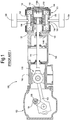
- Fig.2 illustrates a schematic sectional view of a cylinder and relevant components of a double-acting reciprocating compressor 1 according to the present disclosure in one embodiment.
- the section is taken along the axis of the reciprocating compressor cylinder.
- the compressor 1 can comprise a compressor head 3, a compressor frame 5 and a distance piece 7, which connects the compressor head 3 to the compressor frame 5.
- the compressor head 3 contains the compression chamber, as will be described below.
- a crankshaft 9 is arranged in the compressor frame 5 for rotation around a shaft axis 9A.
- a prime mover not shown, drives the crankshaft 9 into rotation around the axis 9A.
- the prime mover can be a reciprocating internal combustion engine, such as a Diesel engine. In other embodiments, the prime mover can be a reciprocating external combustion engine, such as a Stirling engine.
- the reciprocating compressor 1 can also be driven by a gas turbine engine, by a steam turbine, or by an electric motor, for instance.
- a connecting rod 11 connects the crankshaft 9 to a crosshead 13.
- the crosshead 13 is guided along cross-head guides 15 housed in the frame 5.
- the rotation motion of the crankshaft 9 (arrow f9) is thus converted into a reciprocating motion of the crosshead 13 (arrow f13).
- a piston rod 17 connects the crosshead 13 to a piston 19, which is adapted to reciprocatingly slide in a chamber 21 of a compressor barrel 18.
- the piston 19 divides the chamber 21 in two compression chambers, namely a head-end chamber 21A, and a crank-end chamber 21B.
- One or more respective suction valves are provided to fluidly connect the head-end chamber 21A and the crank-end chamber 21B selectively with a gas inlet plenum 20.
- One or more respective delivery valves are further provided to fluidly connect the head-end chamber 21A and the crank-end chamber 21B selectively with a gas discharge plenum 22.
- the gas inlet plenum 20 is fluidly coupled to a low-pressure gas source 31, and the gas discharge plenum 22 is fluidly coupled to a high-pressure gas source 33.
- a single gas suction valve for each chamber 21A, 21B and a single gas delivery valve for each chamber 21A, 21B are visible.
- a plurality of such gas suction valves and gas delivery valves can be provided for each one of said head-end chamber 21A and crank-end chamber 21B.
- a first gas suction valve 23A is shown for fluidly connecting the head-end chamber 21A with the gas inlet plenum 22 and a second gas suction valve 23B is shown for fluidly connecting the crank-end chamber 21B to the gas inlet plenum 22.
- a first gas delivery valve 25A is provided for fluidly connecting the head-end chamber 21A with the gas discharge plenum 25 and a second gas delivery valve 25B is shown for fluidly connecting the crank-end chamber 21B to the gas discharge plenum 22.
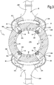
- a total of four gas valves namely two gas suction valves and two gas delivery valves, are shown in fluid communication with the head-end side chamber 21A.
- a similar arrangement is provided for the crank-end chamber 21B.
- valves can be provided for each chamber.
- the gas suction valves 23A, 23B and the gas delivery valves 25A, 25B can be automatic valves, i.e. valves which automatically open and close in response to a pressure differential thereacross.
- the reciprocating motion of the piston 19 according to double arrow f19 causes gas to be sucked through gas suction valves 23A, 23B from the gas inlet plenum 20 in the head-end chamber 21A and in the crank-end chamber 21B, selectively. Simultaneously, gas is compressed is selectively compressed in the crank-end chamber 21B and in the head-end chamber 21A and discharged through the gas delivery valves 25B, 25A in the discharge plenum 22.
- the gas suction valves 23A, 23B and the gas delivery valves 25A, 25B can be housed in respective valve seats schematically shown at 27A, 27B for the gas suction valves 23A, 23B and at 29A, 29B for the gas delivery valves 25A, 25B, see also Fig.3 .
- the valve seats 27A, 27B are in fluid communication with the respective head-end chamber 21A and crank-end chamber 21B through respective gas suction ports 30 ( Fig.3 ).
- the valve seats 29A, 29B are in fluid communication with the respective head-end chamber 21A and crank-end chamber 21B through respective gas delivery ports 32 ( Fig.3 ).
- valve seats 27A, 27B and 29A, 29B are arranged in the compressor barrel 18, develop along the thickness thereof and have respective gas inlet apertures 34 and gas outlet apertures 36 on the outer surface of compressor barrel 18.
- the gas inlet plenum 20 and the gas discharge plenum 22 are mounted on the outer surface of the compressor barrel 18.
- the gas inlet plenum 20 can be provided with a total number of gas inlet ducts 20A equal to the total number of suction valves 23A, 23B of the compressor head 3.
- the separate and independent gas ducts 20A depart from a central volume 20B of the gas inlet plenum 20 and extend to the compressor barrel 18, and more specifically towards the relevant suction valves 23A, 23B of both the crank-end and head-end of the compressor.
- the separate suction ducts 20A provide independent fluid coupling between the central common volume 20B and each suction valve 23A, 23B at both the crank-end side and head-end side of the reciprocating compressor.
- the gas discharge plenum 22 can in turn be comprised of a total number of gas ducts 22A equal to the total number of delivery valves 25B of the compressor head 3.
- the separate and independent gas discharge ducts 22A depart from the barrel 18, and more specifically from the respective discharge valves of both the crank-end and head-end of the compressor, and extend towards a central volume 22B of the discharge plenum 22.
- the separate discharge ducts 22A provide independent fluid coupling between the central common volume 22B and each delivery valve 25A, 25B at both the crank-end side and head-end side of the reciprocating compressor.
- each separate duct 20A and 22A can be designed and dimensioned independently of the other ducts. It is thus possible to ameliorate the fluid flow conditions and reduce fluid-dynamic losses for each valve and thus improve the overall efficiency of the compressor.
- the arrangement of the gas ports and apertures of the gas discharge plenum 22, the gas inlet plenum 20 and the valve seats 27A, 27B, 29A, 29B is such that gas flows in a substantially axial direction from the gas outlet 20A of the gas inlet plenum 20 towards and through the valve seats 27A, 27B and the respective gas suction valves 23A, 23B. Moreover, the gas flows in a substantially axial direction through the gas delivery valves 25A, 25B, the valve seats 29A, 29B towards the gas ports 22A of the gas discharge plenum 22.
- axial direction as used herein can be understood as a direction substantially parallel to an axial extension of the gas suction valves 23A, 23B and gas delivery valves 25A, 25B, along which the gas flows through the respective valves.
- the gas inlet plenum 20 and the gas discharge plenum 22 By arranging the gas inlet plenum 20 and the gas discharge plenum 22 outside the barrel 18, the gas flow is optimized, since no sharp 90° bent is required for the gas upon entering the valve seats.
- the gas inlet plenum 20 and the gas discharge plenum 22 can be designed with a higher degree of freedom, as they do not require to be housed in the reduced space available within the thickness of the compressor barrel, as in the reciprocating compressors of the current art.
- the shape of the inner gas passages in the gas inlet plenum 20 and gas discharge plenum 22 can be optimized for reduced pressure losses.
- the barrel 18 can have a simple cylindrical shape, and can be obtained by forging or centrifugal casting.
- the valve seats 27A, 27B and 29A, 29B can be produced by simple machining through the cylindrical wall of the semi-finished barrel 18.
- cooling ducts 38 can be provided in the semi-finished barrel 18.
- the cooling ducts 38 extend parallel to the barrel axis, i.e. parallel to the direction of the reciprocating motion of the piston 19 in the chamber 21, as shown in Fig. 3 . Machining of the cooling ducts 38 is simple and inexpensive, if compared to the manufacturing of complex cooling ducts in the barrels of the current art.
- valve seats 27A, 27B, 29A, 29B and/or the cooling ducts 38 can be produced during casting.
- the cooling ducts and/or the valve seats are produced by chip-removal machining.
- the gas inlet plenum, or the gas discharge plenum or both are manufactured by additive manufacturing.
- This manufacturing technique allows the production of components having a complex shape at low cost.
- the shape of the gas flow paths inside the gas inlet plenum and the gas discharge plenum can be designed such as to achieve optimum flow conditions and minimize losses.
- Additive manufacturing allows production of flow ducts of substantially any shape, no matter how complex they are.
- the additive manufacturing process can be selected from the group comprising: Selective Laser Sintering (SLS), Powder bed fusion (PBF), Selective Laser Melting (SLM), Direct Metal Laser Sintering (DMLS), Electron Beam Melting (EBM), Multi Jet Fusion (MJF).
- Both the gas inlet plenum and the gas discharge plenum can be manufactured as a single, monolithic piece of machinery, without the need for connecting to one another two or more elements, e.g. by soldering, welding, screwing or the like.
- the resulting single-piece monolithic plenum meets higher quality standards. Production of scraps or defective components is prevented or limited. The manufacturing process is faster and requires less manufacturing skill.
- the gas inlet plenum 20 and the gas discharge plenum 22 can be mounted around the compressor barrel 18 and coupled thereto by any suitable means.
- connecting flanges 34A, 36A can be provided around each inlet aperture 34 and each outlet aperture 36.
- the flanges can be connected to the compressor barrel 18 e.g. by means of screws, such that the gas inlet plenum and the gas discharge plenum can be easily disassembled from the compressor barrel 18, e.g. in order to repair or replace the suction valves and delivery valves, as required.
Landscapes
- Engineering & Computer Science (AREA)
- Mechanical Engineering (AREA)
- General Engineering & Computer Science (AREA)
- Compressor (AREA)
- Compressors, Vaccum Pumps And Other Relevant Systems (AREA)
Abstract
Description
- The subject matter disclosed herein generally relates to compressors and more specifically to reciprocating compressors. In particular, embodiments of the present disclosure concern double-acting reciprocating compressors.
- Reciprocating compressors are used in several industrial fields for compressing a gas, in particular when relatively small gas flow rates require to be compressed with a high compression ratio.
- Exemplary embodiments of double-acting reciprocating compressors are disclosed in
US Pat. N. 7,418,355 ,US Pat. N. 8,807,959 and inUS Pat. N. 8,203,350 . A reciprocating compressor comprises a compressor cylinder forming a cylinder chamber therein. A piston is arranged in the cylinder chamber and is driven into reciprocating motion by a prime mover, such as an electric motor, a turbine or a reciprocating internal or external combustion engine, such as a Stirling engine. A crankshaft and a connecting rod mechanism converts the rotary motion of a motor shaft into reciprocating motion of the piston. The connecting rod is usually drivingly coupled to the piston through a cross-head and a piston rod. - A valve arrangement provides for gas delivery into the cylinder chamber and gas discharge from the cylinder chamber. In double-acting reciprocating compressors the piston divides the cylinder chamber into a first compression chamber and a second compression chamber. At least one suction valve and one delivery valve are fluidly coupled to the first compression chamber, and at least a further suction valve and a further delivery valve are fluidly coupled to the second compression chamber. The reciprocating motion of the piston in the cylinder chamber causes gas to be sucked in one of the compression chambers through the respective suction valve, while gas is compressed in the other compression chamber and discharged through the respective delivery valve, when a delivery pressure is achieved at which the delivery valve is opened.
- Suction valves and delivery valves are usually automatic valves, which automatically open and close in response to a pressure differential thereacross.
- The suction valves are fluidly coupled to an inlet plenum, which feeds gas at a lower pressure to the cylinder chamber. The delivery valves are in turn fluidly coupled to a discharge plenum, which collects gas at a higher pressure from the cylinder chamber.
-
Fig.1 illustrates a double-acting reciprocatingcompressor 100 of the current art. Thecompressor 100 comprises acompressor head 101, acompressor frame 102 and adistance piece 103, which connects thecompressor head 101 to thecompressor frame 102. Acrankshaft 104 is arranged in thecompressor frame 102. Thecrankshaft 104 rotates around arotation axis 106. A prime mover, not shown, drives thecrankshaft 104 into rotation. A connectingrod 108 transmits the motion from thecrankshaft 104 to acrosshead 110, which moves reciprocatingly in acrosshead guide 112. Apiston rod 114 connects thecrosshead 110 to apiston 116, which is adapted to reciprocatingly slide in achamber 118 of acompressor cylinder 120. Thepiston 116 divides thechamber 118 in a first compression chamber and a second compression chamber. In some embodiments, the first and second compression chambers can be a head-end chamber 118A, and a crank-end chamber 118B. A process gas is selectively sucked into each one of said head-end and crank-end chambers end chamber 118A and crank-end chamber 118B are provided each with at least one suction valve and one delivery valve. The suction, compression and discharge process is performed alternatively in the two chambers, i.e. when gas is sucked into one of the head-end chamber 118A and crank-end chamber 118B, gas in the other of said head-end chamber 118A and crank-end chamber 118B is compressed and discharged. -
Suction valves 122 of both crank-end chamber 118B and head-end chamber 118A are fluidly coupled to aninlet plenum 126, which is in turn fluidly coupled to agas source 128.Delivery valves 124 of both crank-end chamber 118B and head-end chamber 118A are fluidly coupled to adischarge plenum 130, which is in turn fluidly coupled to agas output 134. Theinlet plenum 126 and thedischarge plenum 130 are both formed in abarrel 132, which in turn forms a cylindrical side wall of thechamber 118. The gaseous flow through theinlet plenum 126 and thedischarge plenum 130 and respective suction valves and delivery valves is complex and involves sharp bends due to the position of the valves in respective valve seats formed in thebarrel 132. Specifically, gas enters the valve seats in a direction orthogonal to the axial direction of the valves, such that the gas flow turns by 90° when flowing from the inlet plenum into the suction valves and when flowing from the delivery valves into the discharge plenum. -
Cooling ducts 136 are further provided in thebarrel 132. - The need to provide inlet plenum, discharge plenum, valve seats and cooling ducts therein, makes the barrel 132 a quite complex and expensive piece of machinery, which must be manufactured by iron or steel casting. Casting of complicated components is time consuming and may frequently lead to scraps.
- The shape of the inlet plenum and discharge plenum is restricted by the structure of the barrel. Mechanical constraints result in suboptimal fluid-dynamic design of the gas inlet and discharge plenums, which in turn causes fluid-dynamic losses and reduction of the overall efficiency of the compressor.
- Also, cooling of the compressor head is inefficient and manufacturing of the cooling ducts is rendered complicated by the combined presence of valve seats, plenums and cooling arrangements in the barrel.
-
GB1367164 -
CN104747405 discloses a double-acting reciprocating compressor, wherein each one of the crank-end chamber and head-end chamber of the compressor is provided with two suction valves and two discharge valves, respectively. The pair of suction valves associated to the crank-end chamber are fluidly coupled to a respective suction plenum. The two plenums connected to the suction valves of the head-end chamber and crank-end chamber are in turn coupled to a suction duct. Similarly, the two plenums connected to the discharge valves of the head-end chamber and crank-end chamber are in turn coupled to a discharge duct. - Both the above mentioned plenum configurations have a limited fluid-dynamic efficiency and are complex to manufacture.
- A need therefore exists, for improvements in the design of reciprocating compressors, in particular double-acting reciprocating compressors, in order to solve or alleviate one or more of the drawbacks of the compressors of the current art.
- According to one aspect, the present disclosure concerns a manufacturing method for manufacturing a cylinder for a reciprocating compressor. The method comprises a step of manufacturing a compressor barrel comprised of a cylinder chamber, a first suction valve seat, fluidly coupled to the cylinder chamber through a respective first gas suction port; and a first delivery valve seat, fluidly coupled to the cylinder chamber through a respective first gas delivery port. The method further comprises the step of manufacturing by additive manufacturing a gas inlet plenum and further manufacturing by additive manufacturing a gas discharge plenum, separately from the compressor barrel.
- The gas inlet plenum and the gas discharge plenum can be attached around the compressor barrel in fluid communication with the gas suction port and the gas delivery port. The gas inlet plenum and the gas discharge plenum can thus be designed according to optimization criteria, to minimize the gas pressure losses along the gas path, without being subjected to mechanical constraints imposed by the shape of the compressor barrel.
- According to a further aspect, a manufacturing method for manufacturing a cylinder for a reciprocating compressor is described herein, which comprises the following steps:
- mounting a first suction valve in a first suction valve seat provided in a compressor barrel and fluidly coupled through a first gas suction port to a cylinder chamber arranged in the compressor barrel;
- mounting a first delivery valve in a first delivery valve seat provided in the compressor barrel and fluidly coupled to the cylinder chamber through a first gas delivery port;
- mounting a gas inlet plenum on the compressor barrel and in fluid communication with first suction valve seat;
- mounting a gas discharge plenum on the compressor barrel and in fluid communication with the first delivery valve.
- According to a yet further aspect, a reciprocating compressor is disclosed, comprising a compressor barrel with a cylinder chamber therein and a piston, adapted for reciprocatingly sliding in the cylinder chamber. The compressor further comprises a first suction valve fluidly coupled to the cylinder chamber and a first delivery valve fluidly coupled to the cylinder chamber. Furthermore, the compressor comprises a gas inlet plenum fluidly coupled to the first suction valve and a gas discharge plenum fluidly coupled to the first delivery valve. The gas inlet plenum and the gas discharge plenum are produced by additive manufacturing and are mechanically connected to the compressor barrel and external thereto.
- Features and embodiments are disclosed here below and are further set forth in the appended claims, which form an integral part of the present description. The above brief description sets forth features of the various embodiments of the present invention in order that the detailed description that follows may be better understood and in order that the present contributions to the art may be better appreciated. There are, of course, other features of the invention that will be described hereinafter and which will be set forth in the appended claims. In this respect, before explaining several embodiments of the invention in details, it is understood that the various embodiments of the invention are not limited in their application to the details of the construction and to the arrangements of the components set forth in the following description or illustrated in the drawings. The invention is capable of other embodiments and of being practiced and carried out in various ways. Also, it is to be understood that the phraseology and terminology employed herein are for the purpose of description and should not be regarded as limiting.
- As such, those skilled in the art will appreciate that the conception, upon which the disclosure is based, may readily be utilized as a basis for designing other structures, methods, and/or systems for carrying out the several purposes of the present invention. It is important, therefore, that the claims be regarded as including such equivalent constructions insofar as they do not depart from the spirit and scope of the present invention.
- A more complete appreciation of the disclosed embodiments of the invention and many of the attendant advantages thereof will be readily obtained as the same becomes better understood by reference to the following detailed description when considered in connection with the accompanying drawings, wherein:
-
Fig.1 illustrates a sectional view of a double-acting reciprocating compressor of the current art; -
Fig.2 illustrates a sectional view of a double-acting reciprocating compressor according to an embodiment of the present disclosure; -
Fig.3 illustrates a sectional view taken along the line III-III ofFig.2 ; -
Fig.4 illustrates a flowchart summarizing manufacturing methods according to the present disclosure. - The following detailed description of the exemplary embodiments refers to the accompanying drawings. The same reference numbers in different drawings identify the same or similar elements. Additionally, the drawings are not necessarily drawn to scale. Also, the following detailed description does not limit the invention. Instead, the scope of the invention is defined by the appended claims.
- Reference throughout the specification to "one embodiment" or "an embodiment" or "some embodiments" means that the particular feature, structure or characteristic described in connection with an embodiment is included in at least one embodiment of the subject matter disclosed. Thus, the appearance of the phrase "in one embodiment" or "in an embodiment" or "in some embodiments" in various places throughout the specification is not necessarily referring to the same embodiment(s). Further, the particular features, structures or characteristics may be combined in any suitable manner in one or more embodiments.
- The exemplary reciprocating compressors disclosed herein alleviate or solve the drawbacks and limitations of the prior art by separating the gas inlet plenum and gas discharge plenum from the compressor barrel. The design of both the gas inlet plenum and the gas discharge plenum can thus be optimized from a fluid-dynamic and acoustic perspective, since less mechanical constraints are present. The shape of the inlet plenum and discharge plenum do not have to conform to the shape of the barrel, the cooling ducts and valve seats housed therein. By producing the gas inlet plenum and the gas discharge plenum by additive manufacturing, a higher degree of freedom in shaping the plenum and various sections thereof is achieved.
- The orientation of the inlet plenum and discharge plenum with respect to the position of the suction valves and delivery valves can be optimized. More space is available in the wall of the barrel to accommodate the valve seats and the cooling ducts. Also the shape of the cooling ducts can be ameliorated from the point of view of heat exchange efficiency, as well as from the point of view of machining.
- The barrel can be more easily manufactured and less expensive production techniques, rather than iron or steel casting, can be used. For instance, the barrel can be manufactured by forging or centrifugal casting, which makes the overall manufacturing process quicker, less expensive and less prone to generate scraps.
- Since the gas inlet plenum and gas discharge plenum are produced by additive manufacturing, optimal design can be achieved, which result in reduction of fluid-dynamic losses in the inlet and discharge gas flows.
- While the compressor structure and the manufacturing processes disclosed herein can be beneficial also for the production of single-acting reciprocating compressors, they are particularly beneficial for the production of double-acting reciprocating compressors, where the shape of the gas inlet plenum and gas discharge plenum is particularly complex due to the higher number of suction valves and delivery valves provided at both ends of the compressor barrel.
- A double-acting reciprocating compressor comprises a cylinder comprised of a compressor barrel and a cylinder chamber formed in the barrel. The cylinder chamber is divided in a so-called head-end chamber and a so-called crank-end chamber by a piston, arranged for reciprocatingly sliding therein. The head-end chamber is fluidly coupled to a first suction valve through a first gas suction port and to a first delivery valve through a first gas delivery port. The crank-end chamber is fluidly coupled to a second suction valve through a second gas suction port and to a second delivery valve through a second gas delivery port.
- Thus, the double-acting reciprocating compressor is adapted to suck gas in one of the crank-end chamber and head-end chamber through the respective suction valve, while gas is compressed in the other of the crank-end chamber and head-end chamber and finally delivered through the respective delivery valve.
- Each crank-end chamber and head-end chamber can be fluidly coupled to more than one suction valve and one delivery valve. For instance, two respective suction valves and two respective delivery valves can be fluidly coupled to each one of said head-end chamber and crank-end chamber, to maximize gas flow and minimize head losses.
- The larger the number of suction valves and delivery valves, the more beneficial the use of gas inlet plenum and gas discharge plenum manufactured separately from the compressor barrel, as this gives more freedom in shaping the gas ducts in the gas inlet and discharge plenums, and imposes less space and mechanical constraints.
- All suction valves can be fluidly coupled to a single gas inlet plenum. All delivery valves can be fluidly coupled to a single gas discharge plenum.
- In particularly advantageous embodiments, each suction valve and delivery valve is fluidly coupled to a central portion or volume of the respective plenum by an independent, i.e. separate duct. Each duct can be designed independently of the other ducts of the respective plenum, for optimal fluid-dynamic performance and improved acoustic behavior, i.e. reduced pressure waves in the duct. While in some reciprocating compressors of the current art this achieved, for instance, by providing resonators coupled to each valve, which introduce fluid-dynamic losses in the gas flow, designing each duct separately from the other achieves improvements in acoustic conditions in the gas flow, without negatively affecting the fluid-dynamic efficiency of the compressor.
- The suction valves and the delivery valves can be automatic valves, which open and close responsive to a pressure difference thereacross.
- The piston can be connected to a rotary crankshaft trough a connecting rod. Large reciprocating compressors, especially double-acting reciprocating compressors as disclosed herein are further provided with a piston rod and a crosshead. The piston, the piston rod and the cross-head are controlled according to a reciprocating rectilinear motion imparted to the crosshead by the rotary crankshaft and the connecting rod.
- Turning now to the drawings,
Fig.2 illustrates a schematic sectional view of a cylinder and relevant components of a double-actingreciprocating compressor 1 according to the present disclosure in one embodiment. The section is taken along the axis of the reciprocating compressor cylinder. - According to embodiments disclosed herein, the
compressor 1 can comprise acompressor head 3, a compressor frame 5 and a distance piece 7, which connects thecompressor head 3 to the compressor frame 5. Thecompressor head 3 contains the compression chamber, as will be described below. - A
crankshaft 9 is arranged in the compressor frame 5 for rotation around ashaft axis 9A. A prime mover, not shown, drives thecrankshaft 9 into rotation around theaxis 9A. The prime mover can be a reciprocating internal combustion engine, such as a Diesel engine. In other embodiments, the prime mover can be a reciprocating external combustion engine, such as a Stirling engine. Thereciprocating compressor 1 can also be driven by a gas turbine engine, by a steam turbine, or by an electric motor, for instance. - A connecting
rod 11 connects thecrankshaft 9 to acrosshead 13. Thecrosshead 13 is guided along cross-head guides 15 housed in the frame 5. The rotation motion of the crankshaft 9 (arrow f9) is thus converted into a reciprocating motion of the crosshead 13 (arrow f13). Apiston rod 17 connects thecrosshead 13 to apiston 19, which is adapted to reciprocatingly slide in achamber 21 of acompressor barrel 18. Thepiston 19 divides thechamber 21 in two compression chambers, namely a head-end chamber 21A, and a crank-end chamber 21B. - One or more respective suction valves are provided to fluidly connect the head-
end chamber 21A and the crank-end chamber 21B selectively with agas inlet plenum 20. One or more respective delivery valves are further provided to fluidly connect the head-end chamber 21A and the crank-end chamber 21B selectively with agas discharge plenum 22. - The
gas inlet plenum 20 is fluidly coupled to a low-pressure gas source 31, and thegas discharge plenum 22 is fluidly coupled to a high-pressure gas source 33. - In the sectional view of
Fig. 2 a single gas suction valve for eachchamber chamber end chamber 21A and crank-end chamber 21B. Specifically in the sectional view ofFig. 2 a firstgas suction valve 23A is shown for fluidly connecting the head-end chamber 21A with thegas inlet plenum 22 and a secondgas suction valve 23B is shown for fluidly connecting the crank-end chamber 21B to thegas inlet plenum 22. Similarly, a firstgas delivery valve 25A is provided for fluidly connecting the head-end chamber 21A with the gas discharge plenum 25 and a secondgas delivery valve 25B is shown for fluidly connecting the crank-end chamber 21B to thegas discharge plenum 22. - In the cross-sectional view of
Fig.3 a total of four gas valves, namely two gas suction valves and two gas delivery valves, are shown in fluid communication with the head-end side chamber 21A. A similar arrangement is provided for the crank-end chamber 21B. - In other embodiments, not shown, a different number of valves can be provided for each chamber.
- The
gas suction valves gas delivery valves - As known, the reciprocating motion of the
piston 19 according to double arrow f19 causes gas to be sucked throughgas suction valves gas inlet plenum 20 in the head-end chamber 21A and in the crank-end chamber 21B, selectively. Simultaneously, gas is compressed is selectively compressed in the crank-end chamber 21B and in the head-end chamber 21A and discharged through thegas delivery valves discharge plenum 22. - The
gas suction valves gas delivery valves gas suction valves gas delivery valves Fig.3 . The valve seats 27A, 27B are in fluid communication with the respective head-end chamber 21A and crank-end chamber 21B through respective gas suction ports 30 (Fig.3 ). The valve seats 29A, 29B are in fluid communication with the respective head-end chamber 21A and crank-end chamber 21B through respective gas delivery ports 32 (Fig.3 ). - The valve seats 27A, 27B and 29A, 29B are arranged in the
compressor barrel 18, develop along the thickness thereof and have respectivegas inlet apertures 34 andgas outlet apertures 36 on the outer surface ofcompressor barrel 18. - The
gas inlet plenum 20 and thegas discharge plenum 22 are mounted on the outer surface of thecompressor barrel 18. Thegas inlet plenum 20 can be provided with a total number ofgas inlet ducts 20A equal to the total number ofsuction valves compressor head 3. The separate andindependent gas ducts 20A depart from acentral volume 20B of thegas inlet plenum 20 and extend to thecompressor barrel 18, and more specifically towards therelevant suction valves separate suction ducts 20A provide independent fluid coupling between the centralcommon volume 20B and eachsuction valve - The
gas discharge plenum 22 can in turn be comprised of a total number ofgas ducts 22A equal to the total number ofdelivery valves 25B of thecompressor head 3. The separate and independentgas discharge ducts 22A depart from thebarrel 18, and more specifically from the respective discharge valves of both the crank-end and head-end of the compressor, and extend towards acentral volume 22B of thedischarge plenum 22. Theseparate discharge ducts 22A provide independent fluid coupling between the centralcommon volume 22B and eachdelivery valve - With the above described configuration of the
gas inlet plenum 20 andgas discharge plenum 22, eachseparate duct - Acoustic resonance phenomena can be better controlled and reduced or eliminated by adapting the length of each duct to the expected operating conditions of each valve, independently from the other valves of the compressor, without resorting to resonators in the suction or delivery ducts, which would negatively affect the fluid dynamic performances of the compressor.
- These advantages are particularly beneficial in double-acting reciprocating compressors, where different flow and resonance conditions may be present at the crank-end and head-end of the compressor.
- The arrangement of the gas ports and apertures of the
gas discharge plenum 22, thegas inlet plenum 20 and the valve seats 27A, 27B, 29A, 29B is such that gas flows in a substantially axial direction from thegas outlet 20A of thegas inlet plenum 20 towards and through the valve seats 27A, 27B and the respectivegas suction valves gas delivery valves gas ports 22A of thegas discharge plenum 22. - The term "axial direction" as used herein can be understood as a direction substantially parallel to an axial extension of the
gas suction valves gas delivery valves - By arranging the
gas inlet plenum 20 and thegas discharge plenum 22 outside thebarrel 18, the gas flow is optimized, since no sharp 90° bent is required for the gas upon entering the valve seats. Thegas inlet plenum 20 and thegas discharge plenum 22 can be designed with a higher degree of freedom, as they do not require to be housed in the reduced space available within the thickness of the compressor barrel, as in the reciprocating compressors of the current art. The shape of the inner gas passages in thegas inlet plenum 20 andgas discharge plenum 22 can be optimized for reduced pressure losses. - In addition, manufacturing of the
barrel 18 is made simpler. As a matter of fact, thebarrel 18 can have a simple cylindrical shape, and can be obtained by forging or centrifugal casting. The valve seats 27A, 27B and 29A, 29B can be produced by simple machining through the cylindrical wall of thesemi-finished barrel 18. - Additionally, cooling ducts 38 (
Fig.3 ) can be provided in thesemi-finished barrel 18. In some embodiments, the coolingducts 38 extend parallel to the barrel axis, i.e. parallel to the direction of the reciprocating motion of thepiston 19 in thechamber 21, as shown inFig. 3 . Machining of thecooling ducts 38 is simple and inexpensive, if compared to the manufacturing of complex cooling ducts in the barrels of the current art. - In other embodiments, the valve seats 27A, 27B, 29A, 29B and/or the
cooling ducts 38 can be produced during casting. - According to some embodiments, the cooling ducts and/or the valve seats are produced by chip-removal machining.
- The gas inlet plenum, or the gas discharge plenum or both are manufactured by additive manufacturing. This manufacturing technique allows the production of components having a complex shape at low cost. The shape of the gas flow paths inside the gas inlet plenum and the gas discharge plenum can be designed such as to achieve optimum flow conditions and minimize losses. Additive manufacturing allows production of flow ducts of substantially any shape, no matter how complex they are. The additive manufacturing process can be selected from the group comprising: Selective Laser Sintering (SLS), Powder bed fusion (PBF), Selective Laser Melting (SLM), Direct Metal Laser Sintering (DMLS), Electron Beam Melting (EBM), Multi Jet Fusion (MJF).
- Both the gas inlet plenum and the gas discharge plenum can be manufactured as a single, monolithic piece of machinery, without the need for connecting to one another two or more elements, e.g. by soldering, welding, screwing or the like. The resulting single-piece monolithic plenum meets higher quality standards. Production of scraps or defective components is prevented or limited. The manufacturing process is faster and requires less manufacturing skill.
- The
gas inlet plenum 20 and thegas discharge plenum 22 can be mounted around thecompressor barrel 18 and coupled thereto by any suitable means. For instance, connectingflanges Fig.3 ) can be provided around eachinlet aperture 34 and eachoutlet aperture 36. The flanges can be connected to thecompressor barrel 18 e.g. by means of screws, such that the gas inlet plenum and the gas discharge plenum can be easily disassembled from thecompressor barrel 18, e.g. in order to repair or replace the suction valves and delivery valves, as required. - While the disclosed embodiments of the subject matter described herein have been shown in the drawings and fully described above with particularity and detail in connection with several exemplary embodiments, it will be apparent to those of ordinary skill in the art that many modifications, changes, and omissions are possible without materially departing from the novel teachings, the principles and concepts set forth herein, and advantages of the subject matter recited in the appended claims. Hence, the proper scope of the disclosed innovations should be determined only by the broadest interpretation of the appended claims so as to encompass all such modifications, changes, and omissions. In addition, the order or sequence of any process or method steps may be varied or re-sequenced according to alternative embodiments.
Claims (16)
- A manufacturing method for manufacturing a cylinder for a reciprocating compressor; said method comprising the following steps:manufacturing a compressor barrel comprising a cylinder chamber, a first suction valve seat, fluidly coupled to the cylinder chamber through a respective first gas suction port; and a first delivery valve seat, fluidly coupled to the cylinder chamber through a respective first gas delivery port;manufacturing by additive manufacturing a gas inlet plenum and further manufacturing by additive manufacturing a gas discharge plenum, separately from the compressor barrel.
- The manufacturing method of claim 1, further comprising the steps of: mounting a first suction valve in said first suction valve seat; mounting a first delivery valve in said first delivery valve seat; and mounting the gas inlet plenum and the gas discharge plenum on the compressor barrel and in fluid communication with the first suction valve seat and the first delivery valve seat, respectively.
- The manufacturing method of claim 1 or 2, wherein the compressor barrel comprises: a second suction valve seat, fluidly coupled to the cylinder chamber through a second gas suction port, and a second delivery valve seat, fluidly coupled to the cylinder chamber through a respective second gas delivery port; wherein the gas inlet plenum is configured to provide fluid communication with the first suction valve seat and the second suction valve seat; wherein the gas discharge plenum is configured to provide fluid communication with the first delivery valve seat and the second delivery valve seat; wherein the first suction valve seat and the first delivery valve seat are arranged proximate to a head end of the cylinder chamber; and wherein the second suction valve seat and the second delivery valve seat are arranged proximate to a crank shaft end of the cylinder chamber.
- The method of any one of the preceding claims, wherein the inlet plenum comprises a central common volume wherefrom one separate suction duct for each suction valve extends, each separate suction duct providing independent fluid coupling between the respective suction valve and the central common volume of the inlet plenum.
- The method of any one of the preceding claims, wherein the discharge plenum comprises a central common volume wherefrom one separate discharge duct for each delivery valve extends, each separate discharge duct providing independent fluid coupling between the respective deliver valve and the central common volume of the discharge plenum.
- The method of claim 3 or 4 or 5, further comprising the steps of: mounting a respective suction valve in the first suction valve seat and in the second suction valve seat; mounting a respective delivery valve in the first delivery valve seat and in the second delivery valve seat; mounting the gas inlet plenum on the compressor barrel and in fluid communication with the first suction valve seat and the second suction valve seat; mounting the gas discharge plenum on the compressor barrel and in fluid communication with the first delivery valve seat, and second delivery valve seat.
- The method of one or more of the preceding claims, wherein the compressor barrel is provided with cooling ducts extending substantially parallel to an axial extension of said compressor barrel.
- A manufacturing method for manufacturing a cylinder for a reciprocating compressor; said method comprising the following steps:mounting a first suction valve in a first suction valve seat provided in a compressor barrel and fluidly coupled through a first gas suction port to a cylinder chamber arranged in the compressor barrel;mounting a first delivery valve in a first delivery valve seat provided in the compressor barrel and fluidly coupled to the cylinder chamber through a first gas delivery port;mounting a gas inlet plenum on the compressor barrel and in fluid communication with the first suction valve seat, said gas inlet plenum being made by additive manufacturing;mounting a gas discharge plenum on the compressor barrel and in fluid communication with the first delivery valve seat, said gas inlet plenum being made by additive manufacturing.
- The method of claim 8, further comprising the following steps:mounting a second suction valve in a second suction valve seat provided in the compressor barrel and fluidly coupled through a second gas suction port to the cylinder chamber;mounting a second delivery valve in a second delivery valve seat provided in the compressor barrel and fluidly coupled to the cylinder chamber through a second gas delivery port;mounting the gas inlet plenum in fluid communication with second suction valve seat, and mounting the gas discharge plenum in fluid communication with the second delivery valve seat;wherein a piston is arranged in the cylinder chamber, the piston dividing the cylinder chamber in a head-end chamber and a crank-end chamber, respectively; and wherein the first suction valve and the first delivery valve are in fluid communication with the head-end chamber, and the second suction valve and the second delivery valve are in fluid communication with the crank-end chamber.
- A reciprocating compressor comprising:- a compressor barrel with a cylinder chamber therein;- a piston, adapted for reciprocatingly sliding in the cylinder chamber;- a first suction valve fluidly coupled to the cylinder chamber;- a first delivery valve fluidly coupled to the cylinder chamber;- a gas inlet plenum fluidly coupled to the first suction valve; said gas inlet plenum being made by additive manufacturing; and- a gas discharge plenum fluidly coupled to the first delivery valve; said gas discharge plenum being made by additive manufacturing;wherein the gas inlet plenum and the gas discharge plenum are mechanically connected to the compressor barrel and external thereto.
- The reciprocating compressor of claim 10, wherein the first suction valve is arranged in a first suction valve seat provided in the compressor barrel and in fluid communication with the cylinder chamber through a first gas suction port; and wherein the first delivery valve is arranged in a first delivery valve seat provided in the compressor barrel and in fluid communication with the cylinder chamber through a first gas delivery port.
- The reciprocating compressor of claim 10 or 11, wherein: the piston divides the cylinder chamber in a head-end chamber and a crank-end chamber; the first suction valve and the first delivery valve are fluidly coupled to the head-end chamber; a second suction valve and a second delivery valve are fluidly coupled to the crank-end chamber; the gas inlet plenum is fluidly coupled to the first suction valve and to the second suction valve; and the gas discharge plenum is fluidly coupled to the first delivery valve and to the second delivery valve.
- The reciprocating compressor of claim 12, wherein the second suction valve is arranged in a second suction valve seat provided in the compressor barrel and in fluid communication with the cylinder chamber through a second gas suction port; and wherein the second delivery valve is arranged in a second delivery valve seat provided in the compressor barrel and in fluid communication with the cylinder chamber through a second gas delivery port.
- The reciprocating compressor of one or more of claims 10 to 13, wherein the compressor barrel comprises a plurality of cooling ducts, extending in a longitudinal direction substantially parallel to the direction of movement of the piston in the cylinder chamber.
- The reciprocating compressor of one or more of claims 10 to 14, wherein the inlet plenum comprises a central common volume wherefrom one separate suction duct for each suction valve extends, each separate suction duct providing independent fluid coupling between the respective suction valve and the central common volume of the inlet plenum.
- The reciprocating compressor of one or more of claims 10 to 15, wherein the discharge plenum comprises a central common volume wherefrom one separate discharge duct for each delivery valve extends, each separate discharge duct providing independent fluid coupling between the respective delivery valve and the central common volume of the discharge plenum.
Applications Claiming Priority (2)
| Application Number | Priority Date | Filing Date | Title |
|---|---|---|---|
| IT201700146286 | 2017-12-19 | ||
| IT201800010538 | 2018-11-23 |
Publications (3)
| Publication Number | Publication Date |
|---|---|
| EP3502475A2 true EP3502475A2 (en) | 2019-06-26 |
| EP3502475A3 EP3502475A3 (en) | 2019-10-16 |
| EP3502475B1 EP3502475B1 (en) | 2022-02-23 |
Family
ID=64604583
Family Applications (1)
| Application Number | Title | Priority Date | Filing Date |
|---|---|---|---|
| EP18212273.9A Active EP3502475B1 (en) | 2017-12-19 | 2018-12-13 | A reciprocating compressor and manufacturing method |
Country Status (1)
| Country | Link |
|---|---|
| EP (1) | EP3502475B1 (en) |
Cited By (2)
| Publication number | Priority date | Publication date | Assignee | Title |
|---|---|---|---|---|
| AT527367A1 (en) * | 2023-06-20 | 2025-01-15 | Hoerbiger Wien Gmbh | Contactless sealing piston with piston rod |
| AT527368A1 (en) * | 2023-06-20 | 2025-01-15 | Hoerbiger Wien Gmbh | Contactless sealing piston with piston rod |
Family Cites Families (10)
| Publication number | Priority date | Publication date | Assignee | Title |
|---|---|---|---|---|
| US1791364A (en) * | 1929-06-10 | 1931-02-03 | James O Lewis | Compressor cylinder |
| US1998264A (en) * | 1932-07-30 | 1935-04-16 | Westinghouse Air Brake Co | Compressor |
| GB555944A (en) * | 1941-04-10 | 1943-09-14 | Sulzer Ag | Improvements in or relating to air or gas pumps of the reciprocating type |
| DE2150035A1 (en) * | 1970-10-13 | 1972-04-20 | Frenkel Mark Isaakovich | Cylinder for reciprocating compressor |
| US4006602A (en) * | 1974-08-05 | 1977-02-08 | Fanberg Ralph Z | Refrigeration apparatus and method |
| CN202926543U (en) * | 2012-12-08 | 2013-05-08 | 孙继辉 | Bidirectional air-in air-out inflator |
| US20160341188A1 (en) * | 2014-01-31 | 2016-11-24 | Nuovo Pignone Srl | A compressed natural gas system and method |
| WO2015114080A1 (en) * | 2014-01-31 | 2015-08-06 | Nuovo Pignone Srl | Reciprocating motor-compressor with integrated stirling engine |
| US9546660B2 (en) * | 2014-06-02 | 2017-01-17 | Ingersoll-Rand Company | Compressor system with resonator |
| CN104747405B (en) * | 2015-02-27 | 2017-04-26 | 西安交通大学 | Low-temperature air cylinder working chamber component structure of liquefied natural gas vapor compressor |
-
2018
- 2018-12-13 EP EP18212273.9A patent/EP3502475B1/en active Active
Cited By (2)
| Publication number | Priority date | Publication date | Assignee | Title |
|---|---|---|---|---|
| AT527367A1 (en) * | 2023-06-20 | 2025-01-15 | Hoerbiger Wien Gmbh | Contactless sealing piston with piston rod |
| AT527368A1 (en) * | 2023-06-20 | 2025-01-15 | Hoerbiger Wien Gmbh | Contactless sealing piston with piston rod |
Also Published As
| Publication number | Publication date |
|---|---|
| EP3502475A3 (en) | 2019-10-16 |
| EP3502475B1 (en) | 2022-02-23 |
Similar Documents
| Publication | Publication Date | Title |
|---|---|---|
| US20190186478A1 (en) | Reciprocating compressor and manufacturing method | |
| JP6772373B2 (en) | Reciprocating compressor | |
| US20100303655A1 (en) | Reciprocating pump | |
| KR100619768B1 (en) | Two stage reciprocating compressor and refrigerator using the same | |
| KR102240028B1 (en) | Linear compressor and linear motor | |
| CN104728079B (en) | Compressor and its vent silencer | |
| EP3502475B1 (en) | A reciprocating compressor and manufacturing method | |
| KR101880347B1 (en) | Air compressor | |
| KR100619765B1 (en) | Capacity variable device of reciprocating compressor | |
| JP5760094B2 (en) | Internal combustion engine, exhaust valve and cylinder head therefor, and manufacture, operation and use of internal combustion engine | |
| US7841844B2 (en) | Refrigerants suction guide structure for reciprocating compressor | |
| US20040018106A1 (en) | Compressor and method with an improved inlet and discharge valve arrangement | |
| EP2891801A2 (en) | Compressor and valve assembly thereof for reducing pulsation and/or noise | |
| KR102157883B1 (en) | Linear compressor | |
| US2028331A (en) | Free piston engine compressor | |
| CN113090501B (en) | linear compressor | |
| KR100624818B1 (en) | Linear compressor | |
| CN104471243B (en) | Valveless reciprocating compressor | |
| JP6177566B2 (en) | Reciprocating compressor | |
| CN115306677B (en) | Oil-free lubrication high-pressure swash plate type compressor and control method thereof | |
| KR100608697B1 (en) | Single wear reduction device of two stage reciprocating compressor | |
| JPH039088A (en) | Three-stage compressor | |
| US20090126562A1 (en) | Combined piston-expander compressor | |
| KR100425732B1 (en) | Opposed type reciprocating compressor | |
| TWI853369B (en) | Reciprocating compressor |
Legal Events
| Date | Code | Title | Description |
|---|---|---|---|
| PUAI | Public reference made under article 153(3) epc to a published international application that has entered the european phase |
Free format text: ORIGINAL CODE: 0009012 |
|
| STAA | Information on the status of an ep patent application or granted ep patent |
Free format text: STATUS: THE APPLICATION HAS BEEN PUBLISHED |
|
| AK | Designated contracting states |
Kind code of ref document: A2 Designated state(s): AL AT BE BG CH CY CZ DE DK EE ES FI FR GB GR HR HU IE IS IT LI LT LU LV MC MK MT NL NO PL PT RO RS SE SI SK SM TR |
|
| AX | Request for extension of the european patent |
Extension state: BA ME |
|
| PUAL | Search report despatched |
Free format text: ORIGINAL CODE: 0009013 |
|
| AK | Designated contracting states |
Kind code of ref document: A3 Designated state(s): AL AT BE BG CH CY CZ DE DK EE ES FI FR GB GR HR HU IE IS IT LI LT LU LV MC MK MT NL NO PL PT RO RS SE SI SK SM TR |
|
| AX | Request for extension of the european patent |
Extension state: BA ME |
|
| RIC1 | Information provided on ipc code assigned before grant |
Ipc: F04B 39/10 20060101ALN20190911BHEP Ipc: F04B 39/12 20060101AFI20190911BHEP Ipc: F04B 39/00 20060101ALN20190911BHEP Ipc: F04B 39/06 20060101ALI20190911BHEP |
|
| STAA | Information on the status of an ep patent application or granted ep patent |
Free format text: STATUS: REQUEST FOR EXAMINATION WAS MADE |
|
| 17P | Request for examination filed |
Effective date: 20200414 |
|
| RBV | Designated contracting states (corrected) |
Designated state(s): AL AT BE BG CH CY CZ DE DK EE ES FI FR GB GR HR HU IE IS IT LI LT LU LV MC MK MT NL NO PL PT RO RS SE SI SK SM TR |
|
| STAA | Information on the status of an ep patent application or granted ep patent |
Free format text: STATUS: EXAMINATION IS IN PROGRESS |
|
| 17Q | First examination report despatched |
Effective date: 20201102 |
|
| GRAP | Despatch of communication of intention to grant a patent |
Free format text: ORIGINAL CODE: EPIDOSNIGR1 |
|
| STAA | Information on the status of an ep patent application or granted ep patent |
Free format text: STATUS: GRANT OF PATENT IS INTENDED |
|
| RIC1 | Information provided on ipc code assigned before grant |
Ipc: F04B 39/00 20060101ALN20210830BHEP Ipc: F04B 39/10 20060101ALN20210830BHEP Ipc: F04B 39/06 20060101ALI20210830BHEP Ipc: F04B 39/12 20060101AFI20210830BHEP |
|
| INTG | Intention to grant announced |
Effective date: 20210928 |
|
| GRAS | Grant fee paid |
Free format text: ORIGINAL CODE: EPIDOSNIGR3 |
|
| GRAA | (expected) grant |
Free format text: ORIGINAL CODE: 0009210 |
|
| STAA | Information on the status of an ep patent application or granted ep patent |
Free format text: STATUS: THE PATENT HAS BEEN GRANTED |
|
| AK | Designated contracting states |
Kind code of ref document: B1 Designated state(s): AL AT BE BG CH CY CZ DE DK EE ES FI FR GB GR HR HU IE IS IT LI LT LU LV MC MK MT NL NO PL PT RO RS SE SI SK SM TR |
|
| REG | Reference to a national code |
Ref country code: GB Ref legal event code: FG4D |
|
| REG | Reference to a national code |
Ref country code: CH Ref legal event code: EP |
|
| REG | Reference to a national code |
Ref country code: AT Ref legal event code: REF Ref document number: 1470660 Country of ref document: AT Kind code of ref document: T Effective date: 20220315 |
|
| REG | Reference to a national code |
Ref country code: IE Ref legal event code: FG4D |
|
| REG | Reference to a national code |
Ref country code: DE Ref legal event code: R096 Ref document number: 602018031171 Country of ref document: DE |
|
| REG | Reference to a national code |
Ref country code: NL Ref legal event code: FP |
|
| REG | Reference to a national code |
Ref country code: LT Ref legal event code: MG9D |
|
| REG | Reference to a national code |
Ref country code: AT Ref legal event code: MK05 Ref document number: 1470660 Country of ref document: AT Kind code of ref document: T Effective date: 20220223 |
|
| PG25 | Lapsed in a contracting state [announced via postgrant information from national office to epo] |
Ref country code: SE Free format text: LAPSE BECAUSE OF FAILURE TO SUBMIT A TRANSLATION OF THE DESCRIPTION OR TO PAY THE FEE WITHIN THE PRESCRIBED TIME-LIMIT Effective date: 20220223 Ref country code: RS Free format text: LAPSE BECAUSE OF FAILURE TO SUBMIT A TRANSLATION OF THE DESCRIPTION OR TO PAY THE FEE WITHIN THE PRESCRIBED TIME-LIMIT Effective date: 20220223 Ref country code: PT Free format text: LAPSE BECAUSE OF FAILURE TO SUBMIT A TRANSLATION OF THE DESCRIPTION OR TO PAY THE FEE WITHIN THE PRESCRIBED TIME-LIMIT Effective date: 20220623 Ref country code: NO Free format text: LAPSE BECAUSE OF FAILURE TO SUBMIT A TRANSLATION OF THE DESCRIPTION OR TO PAY THE FEE WITHIN THE PRESCRIBED TIME-LIMIT Effective date: 20220523 Ref country code: LT Free format text: LAPSE BECAUSE OF FAILURE TO SUBMIT A TRANSLATION OF THE DESCRIPTION OR TO PAY THE FEE WITHIN THE PRESCRIBED TIME-LIMIT Effective date: 20220223 Ref country code: HR Free format text: LAPSE BECAUSE OF FAILURE TO SUBMIT A TRANSLATION OF THE DESCRIPTION OR TO PAY THE FEE WITHIN THE PRESCRIBED TIME-LIMIT Effective date: 20220223 Ref country code: ES Free format text: LAPSE BECAUSE OF FAILURE TO SUBMIT A TRANSLATION OF THE DESCRIPTION OR TO PAY THE FEE WITHIN THE PRESCRIBED TIME-LIMIT Effective date: 20220223 Ref country code: BG Free format text: LAPSE BECAUSE OF FAILURE TO SUBMIT A TRANSLATION OF THE DESCRIPTION OR TO PAY THE FEE WITHIN THE PRESCRIBED TIME-LIMIT Effective date: 20220523 |
|
| PG25 | Lapsed in a contracting state [announced via postgrant information from national office to epo] |
Ref country code: PL Free format text: LAPSE BECAUSE OF FAILURE TO SUBMIT A TRANSLATION OF THE DESCRIPTION OR TO PAY THE FEE WITHIN THE PRESCRIBED TIME-LIMIT Effective date: 20220223 Ref country code: LV Free format text: LAPSE BECAUSE OF FAILURE TO SUBMIT A TRANSLATION OF THE DESCRIPTION OR TO PAY THE FEE WITHIN THE PRESCRIBED TIME-LIMIT Effective date: 20220223 Ref country code: GR Free format text: LAPSE BECAUSE OF FAILURE TO SUBMIT A TRANSLATION OF THE DESCRIPTION OR TO PAY THE FEE WITHIN THE PRESCRIBED TIME-LIMIT Effective date: 20220524 Ref country code: FI Free format text: LAPSE BECAUSE OF FAILURE TO SUBMIT A TRANSLATION OF THE DESCRIPTION OR TO PAY THE FEE WITHIN THE PRESCRIBED TIME-LIMIT Effective date: 20220223 Ref country code: AT Free format text: LAPSE BECAUSE OF FAILURE TO SUBMIT A TRANSLATION OF THE DESCRIPTION OR TO PAY THE FEE WITHIN THE PRESCRIBED TIME-LIMIT Effective date: 20220223 |
|
| PG25 | Lapsed in a contracting state [announced via postgrant information from national office to epo] |
Ref country code: IS Free format text: LAPSE BECAUSE OF FAILURE TO SUBMIT A TRANSLATION OF THE DESCRIPTION OR TO PAY THE FEE WITHIN THE PRESCRIBED TIME-LIMIT Effective date: 20220623 |
|
| PG25 | Lapsed in a contracting state [announced via postgrant information from national office to epo] |
Ref country code: SM Free format text: LAPSE BECAUSE OF FAILURE TO SUBMIT A TRANSLATION OF THE DESCRIPTION OR TO PAY THE FEE WITHIN THE PRESCRIBED TIME-LIMIT Effective date: 20220223 Ref country code: SK Free format text: LAPSE BECAUSE OF FAILURE TO SUBMIT A TRANSLATION OF THE DESCRIPTION OR TO PAY THE FEE WITHIN THE PRESCRIBED TIME-LIMIT Effective date: 20220223 Ref country code: RO Free format text: LAPSE BECAUSE OF FAILURE TO SUBMIT A TRANSLATION OF THE DESCRIPTION OR TO PAY THE FEE WITHIN THE PRESCRIBED TIME-LIMIT Effective date: 20220223 Ref country code: EE Free format text: LAPSE BECAUSE OF FAILURE TO SUBMIT A TRANSLATION OF THE DESCRIPTION OR TO PAY THE FEE WITHIN THE PRESCRIBED TIME-LIMIT Effective date: 20220223 Ref country code: DK Free format text: LAPSE BECAUSE OF FAILURE TO SUBMIT A TRANSLATION OF THE DESCRIPTION OR TO PAY THE FEE WITHIN THE PRESCRIBED TIME-LIMIT Effective date: 20220223 Ref country code: CZ Free format text: LAPSE BECAUSE OF FAILURE TO SUBMIT A TRANSLATION OF THE DESCRIPTION OR TO PAY THE FEE WITHIN THE PRESCRIBED TIME-LIMIT Effective date: 20220223 |
|
| REG | Reference to a national code |
Ref country code: DE Ref legal event code: R097 Ref document number: 602018031171 Country of ref document: DE |
|
| PG25 | Lapsed in a contracting state [announced via postgrant information from national office to epo] |
Ref country code: AL Free format text: LAPSE BECAUSE OF FAILURE TO SUBMIT A TRANSLATION OF THE DESCRIPTION OR TO PAY THE FEE WITHIN THE PRESCRIBED TIME-LIMIT Effective date: 20220223 |
|
| PLBE | No opposition filed within time limit |
Free format text: ORIGINAL CODE: 0009261 |
|
| STAA | Information on the status of an ep patent application or granted ep patent |
Free format text: STATUS: NO OPPOSITION FILED WITHIN TIME LIMIT |
|
| 26N | No opposition filed |
Effective date: 20221124 |
|
| PG25 | Lapsed in a contracting state [announced via postgrant information from national office to epo] |
Ref country code: SI Free format text: LAPSE BECAUSE OF FAILURE TO SUBMIT A TRANSLATION OF THE DESCRIPTION OR TO PAY THE FEE WITHIN THE PRESCRIBED TIME-LIMIT Effective date: 20220223 |
|
| P01 | Opt-out of the competence of the unified patent court (upc) registered |
Effective date: 20230526 |
|
| PG25 | Lapsed in a contracting state [announced via postgrant information from national office to epo] |
Ref country code: IT Free format text: LAPSE BECAUSE OF FAILURE TO SUBMIT A TRANSLATION OF THE DESCRIPTION OR TO PAY THE FEE WITHIN THE PRESCRIBED TIME-LIMIT Effective date: 20220223 |
|
| GBPC | Gb: european patent ceased through non-payment of renewal fee |
Effective date: 20221213 |
|
| REG | Reference to a national code |
Ref country code: BE Ref legal event code: MM Effective date: 20221231 |
|
| PG25 | Lapsed in a contracting state [announced via postgrant information from national office to epo] |
Ref country code: LU Free format text: LAPSE BECAUSE OF NON-PAYMENT OF DUE FEES Effective date: 20221213 |
|
| PG25 | Lapsed in a contracting state [announced via postgrant information from national office to epo] |
Ref country code: IE Free format text: LAPSE BECAUSE OF NON-PAYMENT OF DUE FEES Effective date: 20221213 Ref country code: GB Free format text: LAPSE BECAUSE OF NON-PAYMENT OF DUE FEES Effective date: 20221213 |
|
| PG25 | Lapsed in a contracting state [announced via postgrant information from national office to epo] |
Ref country code: FR Free format text: LAPSE BECAUSE OF NON-PAYMENT OF DUE FEES Effective date: 20221231 Ref country code: BE Free format text: LAPSE BECAUSE OF NON-PAYMENT OF DUE FEES Effective date: 20221231 |
|
| PG25 | Lapsed in a contracting state [announced via postgrant information from national office to epo] |
Ref country code: HU Free format text: LAPSE BECAUSE OF FAILURE TO SUBMIT A TRANSLATION OF THE DESCRIPTION OR TO PAY THE FEE WITHIN THE PRESCRIBED TIME-LIMIT; INVALID AB INITIO Effective date: 20181213 |
|
| PG25 | Lapsed in a contracting state [announced via postgrant information from national office to epo] |
Ref country code: CY Free format text: LAPSE BECAUSE OF FAILURE TO SUBMIT A TRANSLATION OF THE DESCRIPTION OR TO PAY THE FEE WITHIN THE PRESCRIBED TIME-LIMIT Effective date: 20220223 |
|
| PG25 | Lapsed in a contracting state [announced via postgrant information from national office to epo] |
Ref country code: MK Free format text: LAPSE BECAUSE OF FAILURE TO SUBMIT A TRANSLATION OF THE DESCRIPTION OR TO PAY THE FEE WITHIN THE PRESCRIBED TIME-LIMIT Effective date: 20220223 |
|
| PG25 | Lapsed in a contracting state [announced via postgrant information from national office to epo] |
Ref country code: MC Free format text: LAPSE BECAUSE OF FAILURE TO SUBMIT A TRANSLATION OF THE DESCRIPTION OR TO PAY THE FEE WITHIN THE PRESCRIBED TIME-LIMIT Effective date: 20220223 |
|
| PG25 | Lapsed in a contracting state [announced via postgrant information from national office to epo] |
Ref country code: MC Free format text: LAPSE BECAUSE OF FAILURE TO SUBMIT A TRANSLATION OF THE DESCRIPTION OR TO PAY THE FEE WITHIN THE PRESCRIBED TIME-LIMIT Effective date: 20220223 |
|
| PG25 | Lapsed in a contracting state [announced via postgrant information from national office to epo] |
Ref country code: MT Free format text: LAPSE BECAUSE OF FAILURE TO SUBMIT A TRANSLATION OF THE DESCRIPTION OR TO PAY THE FEE WITHIN THE PRESCRIBED TIME-LIMIT Effective date: 20220223 |
|
| PG25 | Lapsed in a contracting state [announced via postgrant information from national office to epo] |
Ref country code: TR Free format text: LAPSE BECAUSE OF FAILURE TO SUBMIT A TRANSLATION OF THE DESCRIPTION OR TO PAY THE FEE WITHIN THE PRESCRIBED TIME-LIMIT Effective date: 20220223 |
|
| PGFP | Annual fee paid to national office [announced via postgrant information from national office to epo] |
Ref country code: NL Payment date: 20251119 Year of fee payment: 8 |
|
| REG | Reference to a national code |
Ref country code: CH Ref legal event code: U11 Free format text: ST27 STATUS EVENT CODE: U-0-0-U10-U11 (AS PROVIDED BY THE NATIONAL OFFICE) Effective date: 20260101 |
|
| PGFP | Annual fee paid to national office [announced via postgrant information from national office to epo] |
Ref country code: DE Payment date: 20251126 Year of fee payment: 8 |
|
| PGFP | Annual fee paid to national office [announced via postgrant information from national office to epo] |
Ref country code: CH Payment date: 20260101 Year of fee payment: 8 |