EP3502446A1 - Temperature estimation device - Google Patents
Temperature estimation device Download PDFInfo
- Publication number
- EP3502446A1 EP3502446A1 EP18213314.0A EP18213314A EP3502446A1 EP 3502446 A1 EP3502446 A1 EP 3502446A1 EP 18213314 A EP18213314 A EP 18213314A EP 3502446 A1 EP3502446 A1 EP 3502446A1
- Authority
- EP
- European Patent Office
- Prior art keywords
- temperature
- positions
- controller
- ecu
- ignition
- Prior art date
- Legal status (The legal status is an assumption and is not a legal conclusion. Google has not performed a legal analysis and makes no representation as to the accuracy of the status listed.)
- Withdrawn
Links
Images


Classifications
-
- F—MECHANICAL ENGINEERING; LIGHTING; HEATING; WEAPONS; BLASTING
- F02—COMBUSTION ENGINES; HOT-GAS OR COMBUSTION-PRODUCT ENGINE PLANTS
- F02D—CONTROLLING COMBUSTION ENGINES
- F02D41/00—Electrical control of supply of combustible mixture or its constituents
- F02D41/22—Safety or indicating devices for abnormal conditions
- F02D41/221—Safety or indicating devices for abnormal conditions relating to the failure of actuators or electrically driven elements
-
- B—PERFORMING OPERATIONS; TRANSPORTING
- B62—LAND VEHICLES FOR TRAVELLING OTHERWISE THAN ON RAILS
- B62D—MOTOR VEHICLES; TRAILERS
- B62D5/00—Power-assisted or power-driven steering
- B62D5/04—Power-assisted or power-driven steering electrical, e.g. using an electric servo-motor connected to, or forming part of, the steering gear
- B62D5/0457—Power-assisted or power-driven steering electrical, e.g. using an electric servo-motor connected to, or forming part of, the steering gear characterised by control features of the drive means as such
- B62D5/0481—Power-assisted or power-driven steering electrical, e.g. using an electric servo-motor connected to, or forming part of, the steering gear characterised by control features of the drive means as such monitoring the steering system, e.g. failures
- B62D5/0496—Power-assisted or power-driven steering electrical, e.g. using an electric servo-motor connected to, or forming part of, the steering gear characterised by control features of the drive means as such monitoring the steering system, e.g. failures by using a temperature sensor
-
- G—PHYSICS
- G05—CONTROLLING; REGULATING
- G05B—CONTROL OR REGULATING SYSTEMS IN GENERAL; FUNCTIONAL ELEMENTS OF SUCH SYSTEMS; MONITORING OR TESTING ARRANGEMENTS FOR SUCH SYSTEMS OR ELEMENTS
- G05B19/00—Programme-control systems
- G05B19/02—Programme-control systems electric
- G05B19/04—Programme control other than numerical control, i.e. in sequence controllers or logic controllers
- G05B19/042—Programme control other than numerical control, i.e. in sequence controllers or logic controllers using digital processors
- G05B19/0428—Safety, monitoring
-
- Y—GENERAL TAGGING OF NEW TECHNOLOGICAL DEVELOPMENTS; GENERAL TAGGING OF CROSS-SECTIONAL TECHNOLOGIES SPANNING OVER SEVERAL SECTIONS OF THE IPC; TECHNICAL SUBJECTS COVERED BY FORMER USPC CROSS-REFERENCE ART COLLECTIONS [XRACs] AND DIGESTS
- Y02—TECHNOLOGIES OR APPLICATIONS FOR MITIGATION OR ADAPTATION AGAINST CLIMATE CHANGE
- Y02T—CLIMATE CHANGE MITIGATION TECHNOLOGIES RELATED TO TRANSPORTATION
- Y02T10/00—Road transport of goods or passengers
- Y02T10/10—Internal combustion engine [ICE] based vehicles
- Y02T10/40—Engine management systems
Definitions
- An embodiment of this disclosure relates to a temperature estimation device.
- an elapsed time between an ignition-off event and an ignition-on event is estimated based on the temperatures of heat generating positions such as a drive force transmitting device, a transfer, and a rear differential device and the outside air temperature at the time of an ignition-off event and the temperatures of the heat generating positions and the outside air temperature at the time of an ignition-on event. Then, after an engine which is a drive source is started, an overheat suppressing process for the heat generating positions is performed based on the result of the elapsed time estimation.
- heat generating positions such as a drive force transmitting device, a transfer, and a rear differential device
- JP 2017-87984A it is necessary to install a temperature sensor in order to use the outside air temperature for estimation of an elapsed time.
- it is not possible to estimate the outside air temperature because of failure or the like of the temperature sensor it is not possible to estimate an elapsed time between an ignition-off state and an ignition-on state and thus it is not possible to perform an appropriate overheat suppressing process for heat generating positions.
- a temperature estimation device includes a temperature measuring unit that measures surface temperatures of a plurality of different positions in a controller controlling an operation of a drive source and an estimation unit that estimates at least one of an outside air temperature in the vicinity of the controller and an elapsed time between when the controller is stopped and when the controller starts to operate again based on the surface temperatures of the plurality of positions that are measured by the temperature measuring unit when the controller is stopped and when the controller starts to operate again and respective thermal time constants that indicate how easily heat is dissipated from the plurality of positions respectively.
- the elapsed time between when the controller is stopped and when the controller starts to operate again may be estimated without estimating the outside air temperature.
- the plurality of positions may be positions in the controller that are different in easiness to be cooled when being left at the same surface temperature. With this configuration, it is possible to more accurately estimate an elapsed time between an ignition-off event and an ignition-on event.
- the plurality of positions may be positions where a change in temperature is great regardless of an operation state of the drive source.
- the plurality of positions may be provided on respective surfaces of a plurality of heat sinks that are installed in the controller and are different from each other in heat dissipation performance.
- the plurality of positions may be positions that are different from each other in distance to a heat source installed in the controller.
- changes in temperatures measured at the positions become significantly different from each other and thus it is possible to more accurately estimate an elapsed time between an ignition-off event and an ignition-on event.
- the embodiment is an example in which the disclosure is applied as a temperature estimation device estimating the temperature of a motor controller that controls a drive motor of an electric power steering device installed in a vehicle.
- the temperature estimation device estimates the temperature of the motor controller which is an example of a heat generating position at the time of an ignition-on event.
- the temperature estimation device performs an appropriate overheat suppressing process with respect to the motor controller based on the estimated temperature.
- Fig. 1 is a hardware block diagram schematically illustrating a hardware configuration of a temperature estimation device 10. As illustrated in Fig. 1 , the temperature estimation device 10 is provided with an ECU 20 which is a motor controller and a power steering drive motor 30 (hereinafter, simply referred to as motor 30).
- ECU 20 which is a motor controller and a power steering drive motor 30 (hereinafter, simply referred to as motor 30).
- the ECU 20 controls the rotation state of the motor 30 while measuring the operation state of a vehicle steering wheel (not shown in Fig. 1 ), a vehicle speed, and the like so as to exhibit an appropriate assist force with respect to a steering operation.
- the ECU 20 estimates the outside air temperature and an elapsed time after stoppage of the ECU 20 based on the surface temperature of the ECU 20.
- the ECU 20 is an example of a controller.
- the ECU 20 is provided with a central processing unit (CPU) 20a, a read only memory (ROM) 20b, a random access memory (RAM) 20c, and a solid state drive (SSD) 20d.
- the CPU 20a performs various kinds of calculation (which will be described later) to control the entire temperature estimation device 10.
- the ROM 20b is a non-volatile storage device and stores a control program P1 or the like executed by the CPU 20a.
- the RAM 20c temporarily stores various kinds of data that the CPU 20a uses in a calculation process.
- the SSD 20d is a non-volatile rewritable storage unit and stores constants such as thermal time constants ⁇ 1 and ⁇ 2 (details will be described later) of the installation positions of temperature sensors 24a and 24b (which will be described later) and the output or the like of the temperature sensors 24a and 24b at the time of an ignition-off event. That is, the ECU 20 has a configuration like a general computer in which the control program P1 stored in the ROM 20b is executed with the RAM 20c used as a work area.
- the ECU 20 is provided with the temperature sensors 24a and 24b, a motor driver 20g, and a current sensor 20h.
- the motor driver 20g generates a drive signal for the motor 30 and supplies the drive signal to the motor 30 so as to control the operation of the motor 30.
- An electric power control element such as a MOSFET or an insulated gate bipolar transistor (IGBT) constitutes the motor driver 20g, for example.
- the current sensor 20h measures the value of a current flowing in the motor driver 20g.
- the CPU 20a in the ECU 20 monitors the value of the current measured by the current sensor 20h.
- the CPU 20a controls the drive signal for the motor 30, which is generated by the motor driver 20g, such that the value of the current becomes a predetermined value.
- the temperature sensors 24a and 24b are installed on a surface of a heat sink, which is installed on a surface of the CPU 20a of the ECU 20, a surface of an electric power control element provided in the motor driver 20g, or the like to promote heat dissipation of a heat generating portion, a surface of a substrate on which a circuit element is mounted, or the like.
- the temperature sensors 24a and 24b measure the surface temperatures of the installation positions thereof.
- the temperature sensors 24a and 24b are examples of a temperature measuring unit and a thermistor, a thermocouple or the like constitutes the temperature sensors.
- the installation position of the temperature sensor 24a and the installation position of the temperature sensor 24b are positions that are different in easiness to be cooled. More specifically, it is desirable that the temperature sensors 24a and 24b are installed on positions that are different in thermal time constant which indicates the degree of response to temperature changes.
- the temperature sensors 24a and 24b may be installed on different heat sinks as illustrated in Fig. 7 which will be described later and the temperature sensors 24a and 24b may be installed on different positions on the same heat sink.
- the number of temperature sensors to be installed is not limited to two. That is, three or more temperature sensors 24a, 24b, 24c (not shown), ..., and the like may be installed on positions that are different in thermal time constant.
- a signal or the like indicating the state of an ignition switch 46 is input to the ECU 20 via a network 50 such as a control area network (CAN) in addition to output signals from a steering angle sensor 40, a torque sensor 42, a vehicle speed sensor 44, or the like installed in the vehicle, for example.
- a network 50 such as a control area network (CAN) in addition to output signals from a steering angle sensor 40, a torque sensor 42, a vehicle speed sensor 44, or the like installed in the vehicle, for example.
- CAN control area network
- the steering angle sensor 40 measures a steering angle which is determined by the direction of rotation of the steering wheel and the amount of rotation of the steering wheel.
- the torque sensor 42 measures a torque applied when a vehicle driver operates the steering wheel.
- the vehicle speed sensor 44 measures the vehicle speed of the vehicle.
- the ignition switch 46 is a switch that makes a vehicle drive source such as an engine or a motor operatable.
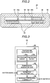
- Fig. 2 is a sectional view of the ECU 20 which illustrates an example of the installation positions of the temperature sensors 24a and 24b.
- the ECU 20 is configured by causing an ECU substrate 54, on which a plurality of circuit elements 52 of the CPU 20a, the ROM 20b, the RAM 20c, the motor driver 20g, and the like are mounted, to be included in an ECU case 56.
- a heat sink 22 that dissipates heat is installed.
- the heat sink 22 is formed of material having a high thermal conductivity such as aluminum or copper.
- the heat sink 22 may be installed to be in contact with the circuit element 52 by using a double-coated adhesive tape having a high thermal conductivity or may be installed on a surface opposite to the circuit element 52 with the ECU substrate 54 interposed threrebetween as illustrated in Fig. 2 .
- the temperature sensor 24a and the temperature sensor 24b are installed on a surface of the ECU substrate 54.
- the temperature sensor 24a is installed on a temperature measurement position Q1.
- the temperature sensor 24b is installed on a temperature measurement position Q2. It is desirable that the temperature measurement position Q1 and the temperature measurement position Q2 are positions that are different in easiness to be cooled when being left at the same surface temperature as much as possible. In addition, it is desirable that the temperature measurement position Q1 and the temperature measurement position Q2 are positions where a change in temperature is great as much as possible. The reason for selecting the temperature measurement position Q1 and the temperature measurement position Q2 as described above will be described later.
- the locations of the temperature measurement position Q1 and the temperature measurement position Q2 that are illustrated in Fig. 2 are merely an example and are not limited thereto. That is, although details will be described later, various locations as illustrated in Figs. 7 and 8 may be set as temperature measurement positions.
- Fig. 3 is a functional block diagram illustrating an example of a functional configuration of the temperature estimation device 10.
- the ECU 20 of the temperature estimation device 10 realizes a temperature measuring unit 60, a temperature acquisition unit 62, an estimation calculating unit 64, and an overheat suppressing control unit 66 shown in Fig. 3 as functional units by deploying the control program P1 in the RAM 20c.
- the temperature measuring unit 60 measures the surface temperature of the temperature measurement position Q1 by using the temperature sensor 24a. In addition, the temperature measuring unit 60 measures the surface temperature of the temperature measurement position Q2 by using the temperature sensor 24b.
- the temperature acquisition unit 62 acquires the surface temperature of the temperature measurement position Q1 by reading the output of the temperature sensor 24a. In addition, the temperature acquisition unit 62 acquires the surface temperature of the temperature measurement position Q2 by reading the output of the temperature sensor 24b.
- the estimation calculating unit 64 estimates an outside air temperature Ta of the vicinity of the ECU 20 and an elapsed time t between an ignition-off event and an ignition-on event based on the surface temperature of the temperature measurement position Q1 to which the temperature sensor 24a is attached and the surface temperature of the temperature measurement position Q2 to which the temperature sensor 24b is attached.
- the estimation calculating unit 64 estimates the outside air temperatures Ta of the vicinities of the temperature sensors 24a and 24b and the elapsed time t between when the ignition switch 46 is turned off and when the ignition switch 46 is turned on (hereinafter, referred to as elapsed time t after turning off of ignition switch 46) based on the outputs of the temperature sensors 24a and 24b at the time of the ignition-off event and the outputs of the temperature sensors 24a and 24b at the time of the ignition-on event.
- the estimation calculating unit 64 is an example of an estimation unit.
- the overheat suppressing control unit 66 predicts the overheat state of the motor 30 based on at least one of the outside air temperatures Ta and the elapsed time t after the turning off of the ignition switch 46 and performs control necessary for suppressing overheat of the motor 30. Specifically, the overheat suppressing control unit 66 predicts the temperatures of a coil and a stator constituting the motor 30. A method of predicting the temperatures of the coil and the stator of the motor 30 by using the outside air temperatures Ta and the elapsed time t after the turning off of the ignition switch 46 may be various proposed methods which are already known.
- the overheat suppressing control unit 66 stops the ECU 20 and stops the motor 30.
- the overheat suppressing control unit 66 performs control in which the drive torque of the motor 30 is reduced and an assist force with respect to a steering operation is reduced. Accordingly, heat generated by the ECU 20 and the motor 30 is suppressed.
- the overheat suppressing control unit 66 lights an indicator (not shown in Fig.
- the 66 may store a fact that the motor 30 has reached the overheat limit and the overheat abnormality has occurred in the SSD 20d as a history (log).
- the stored history is read at the timing of vehicle inspection or the like and can be used for maintenance or the like of the electric power steering device.
- Fig. 4 is a graph illustrating an example of a temporal change in temperature of two different positions in the ECU 20 (position onto which temperature sensor 24a is attached (temperature measurement position Q1 in Fig. 2 ) and position onto which temperature sensor 24b is attached (temperature measurement position Q2 in Fig. 2 )) after stoppage of the ECU 20.
- Fig. 5 is a graph illustrating a method of estimating the outside air temperature and an elapsed time after stoppage of the ECU 20.
- the surface temperature of the ECU 20 at the time of the turning on of the ignition switch 46 will be referred to as Ts2.
- the outside air temperatures of the vicinities of the installation positions of the temperature sensors 24a and 24b will be referred to as Ta and the elapsed time after the turning off of the ignition switch 46 will be referred to as t.
- T 1 Te 1 ⁇ Ta e ⁇ t / ⁇ 1 + Ta
- T 2 Te 2 ⁇ Ta e ⁇ t / ⁇ 2 + Ta
- a time taken for the surface temperature T1 to decrease depends on the thermal time constant ⁇ 1.
- a time taken for the surface temperature T2 to decrease depends on the thermal time constant ⁇ 2.
- the estimation calculating unit 64 estimates the elapsed time t after the turning off of the ignition switch 46 as illustrated in Fig. 4 based on a fact that the surface temperature of the ECU 20 measured by the temperature sensor 24a when the ignition switch 46 is turned on is Ts1 and the surface temperature of the ECU 20 measured by the temperature sensor 24b when the ignition switch 46 is turned on is Ts2.
- the estimation calculating unit 64 calculates the outside air temperature Ta and the elapsed time t by solving Equation 1 and Equation 2 as simultaneous equations in which the outside temperature Ta and the elapsed time t are the unknowns.
- Fig. 5 qualitatively illustrates a process of solving Equation 1 and Equation 2 as the simultaneous equations. That is, a curve C1 shown in Fig. 5 represents a change in outside air temperature Ta1, which is the result of solving Equation 1 with respect to the outside air temperature Ta. In addition, a curve C2 represents a change in outside air temperature Ta2, which is the result of solving Equation 2 with respect to the outside air temperature Ta.
- a point R at which the curve C1 and the curve C2 intersect each other represents an elapsed time to between when the ignition switch 46 is turned off and when the ignition switch 46 is turned on.
- the outside air temperature Ta represented by the point R corresponds to the outside air temperature at the time of the turning on of the ignition switch 46.
- a curve C3 shown in Fig. 5 represents the result of calculating a differential value Ta1-Ta2 with respect to the curve C1 and the curve C2.
- the curve C3 represents that the differential value Ta1-Ta2 is zero at the elapsed time to corresponding to the point R.
- the estimation calculating unit 64 estimates that a time at which the differential value between the curve C1 and the curve C2 becomes zero (that is, time represented by intersection point between curve C1 and curve C2 in graph in Fig. 5 ) is the elapsed time to between when the ignition switch 46 is turned off and when the ignition switch 46 is turned on. Then, the estimation calculating unit 64 estimates that the outside air temperature at that time is Ta.
- the thermal time constant ⁇ 1 of the temperature measurement position Q1 and the thermal time constant ⁇ 2 of the temperature measurement position Q2 are different from each other, the surface temperatures T1 and T2 of the two positions shown in Fig. 4 change at different slopes.
- the temperature measurement position Q1 and the temperature measurement position Q2 are positions that are different in easiness to be cooled when being left at the same surface temperature as much as possible.
- the temperature measurement position Q1 and the temperature measurement position Q2 are positions where a change in temperature is great as much as possible.
- Equation 1 and Equation 2 it is necessary to determine the values of the thermal time constants ⁇ 1 and ⁇ 2 in advance. Therefore, the values of the thermal time constants ⁇ 1 and ⁇ 2 are acquired in advance through an experiment.
- the ECU 20 is operated until the ECU substrate 54 reaches a predetermined temperature, the ECU 20 is turned off to be stopped and changes in temperature of the temperature measurement position Q1 and the temperature measurement position Q2 are measured. Then, the values of the thermal time constants ⁇ 1 and ⁇ 2 are determined based on the measured changes in temperature.
- the determined thermal time constants ⁇ 1 and ⁇ 2 are stored in the SSD 20d (refer to Fig. 1 ), for example.
- Fig. 6 is a flowchart illustrating an example of the flow of a process of estimating the outside air temperature and an elapsed time after stoppage of the ECU 20.
- Fig. 6 is a flowchart illustrating an example of the flow of a process of estimating the outside air temperature and an elapsed time after stoppage of the ECU 20.
- the outline of each process will be described.
- the estimation calculating unit 64 determines whether the ignition is off (step S10). Whether the ignition is off may be determined based on whether the state of the ignition switch 46 is changed from a turned-on state to a turned-off state. When it is determined that the ignition is off (Step S10: Yes), the process proceeds to Step S12 and when it is not determined that the ignition is off (Step S10: No), the determination in Step S10 is repeated.
- the estimation calculating unit 64 acquires the surface temperatures of a plurality of positions at the time of turning off of the ignition from the temperature acquisition unit 62 and stores the surface temperatures in the SSD 20d (Step S12).
- the estimation calculating unit 64 determines whether the ignition is on (Step S14). Whether the ignition is on may be determined based on whether the state of the ignition switch 46 is changed from a turned-off state to a turned-on state. When it is determined that the ignition is on (Step S14: Yes), the process proceeds to Step S16 and when it is not determined that the ignition is on (Step S14: No), the determination in Step S14 is repeated.
- the temperature acquisition unit 62 acquires the surface temperatures Ts1 and Ts2 of the plurality of positions at the time of turning on of the ignition from the temperature sensors 24a and 24b (Step S16).
- the estimation calculating unit 64 reads the surface temperatures Te1 and Te2 of the plurality of positions at the time of the turning off of the ignition from the SSD 20d (Step S18).
- the estimation calculating unit 64 reads the thermal time constants ⁇ 1 and ⁇ 2 from the SSD 20d (Step S20).
- the estimation calculating unit 64 estimates the outside air temperature Ta and the elapsed time to between when the ignition is turned off and when the ignition is turned on (Step S22).
- the overheat suppressing control unit 66 performs overheat suppressing control based on at least one of the surface temperatures Ts1 and Ts2, the surface temperatures Te1 and Te2, and the elapsed time to between when the ignition is turned off and when the ignition is turned on (Step S24).
- the locations of the temperature measurement positions Q1 and Q2 are not limited to those described in the embodiment. Hereinafter, another example of the temperature measurement positions Q1 and Q2 will be described.
- Fig. 7 is an external view of the ECU 20 illustrating a second example of temperature measurement positions on which the temperature sensors 24a and 24b are installed.
- Two heat sinks 22a and 22b are installed on the ECU substrate 54 constituting the ECU 20.
- the heat sinks 22a and 22b are formed of the same material, are the approximately same as each other in mass, and are different from each other in surface area.
- the heat sinks 22a and 22b are different from each other in the number of fins and are different from each other in heat dissipation performance.
- a temperature measurement position Q3 is provided on a surface of the heat sink 22a and the temperature sensor 24a is installed thereon.
- a temperature measurement position Q4 is provided on a surface of the heat sink 22b and the temperature sensor 24b is installed thereon. Since the two heat sinks 22a and 22b are formed of the same material, are the approximately same as each other in mass, and are different from each other in surface area, a thermal time constant ⁇ 1 of the temperature measurement position Q3 and thermal time constant ⁇ 2 of the temperature measurement position Q4 are different from each other.
- the temperature sensors 24a and 24b are installed on positions that are different from each other in easiness to be cooled when being left at the same surface temperature and thus it is possible to accurately estimate the outside air temperature Ta and the elapsed time to between when the ignition switch 46 is turned off and when the ignition switch 46 is turned on.
- the heat sinks 22a and 22b may have the same surface area and may be formed of different materials.
- the heat sink 22a may be formed of aluminum while the heat sink 22b is formed of copper.
- the temperature measurement positions on which the heat sinks 22a and 22b are installed can be made different from each other in thermal time constant. Therefore, it is possible to accurately estimate the outside air temperature Ta and the elapsed time to between when the ignition switch 46 is turned off and when the ignition switch 46 is turned on.
- the heat sink 22a and the heat sink 22b may be different from each other in mass and may have the approximately same surface area.
- the temperature measurement positions on which the heat sinks 22a and 22b are installed can be made different from each other in thermal time constant. Therefore, it is possible to accurately estimate the outside air temperature Ta and the elapsed time to between when the ignition switch 46 is turned off and when the ignition switch 46 is turned on.
- Fig. 8 is an external view of the ECU 20 illustrating a third example of temperature measurement positions on which the temperature sensors 24a and 24b are installed.
- the ECU 20 is provided with a control substrate 54a and a power source substrate 54b.
- Calculation elements such as a CPU, a ROM, a RAM, and an SSD are mounted on the control substrate 54a.
- a drive element such as a power source IC 59 is mounted on the power source substrate 54b.
- the control substrate 54a and the power source substrate 54b are connected to each other via a busbar 58, which is a conductive member.
- a temperature measurement position Q5 is provided in the vicinity of the power source IC 59 which is a heat source and the temperature sensor 24a is installed thereon.
- a temperature measurement position Q6 is provided on the control substrate 54a separated from the heat source and the temperature sensor 24b is installed thereon.
- the temperature measurement positions Q5 and Q6 are different from each other in distance to the heat source. Therefore, a change in temperature measured at the temperature measurement position Q6 is smaller than a change in temperature measured at the temperature measurement position Q5 and thus two curves described in Fig. 4 intersect each other at a larger angle. Accordingly, it is possible to accurately estimate the outside air temperature Ta and the elapsed time to between when the ignition switch 46 is turned off and when the ignition switch 46 is turned on.
- the temperature sensors 24a and 24b (temperature measuring unit 60), which are installed on the plurality of different positions (temperature measurement positions Q1 and Q2) in the ECU 20 (controller) controlling the operation of a drive source, measure the surface temperatures Te1 and Te2 of the temperature measurement positions Q1 and Q2 when the ECU 20 is stopped.
- the temperature sensors 24a and 24b measure the surface temperatures Ts1 and Ts2 of the temperature measurement positions Q1 and Q2 when the ECU 20 starts to operate.
- the estimation calculating unit 64 estimates at least one of the outside air temperature Ta in the vicinity of the ECU 20 and the elapsed time to between when the ECU 20 is stopped and when the ECU 20 starts to operate again based on the surface temperatures Te1 and Te2, the surface temperatures Ts1 and Ts2, the thermal time constant ⁇ 1 which indicates how easily heat is dissipated from the temperature measurement position Q1, and the thermal time constant ⁇ 2 which indicates how easily heat is dissipated from the temperature measurement position Q2. Therefore, it is possible to estimate the outside air temperature Ta without using a temperature sensor for measuring the outside air temperature Ta.
- the temperature measurement positions Q1 and Q2 are positions in the ECU 20 (controller) that are different in easiness to be cooled when being left at the same surface temperature. Therefore, there is a difference between a change in temperature at the temperature measurement position Q1 and a change temperature at the temperature measurement position Q2 and thus it is possible to more accurately estimate the elapsed time to between the ignition-off event and the ignition-on event.
- the temperature measurement positions Q1 and Q2 are positions where a change in temperature is great regardless of the operation state of a drive source, the operation of which is controlled by the ECU 20 (controller). Therefore, there is a difference between a change in temperature at the temperature measurement position Q1 and a change temperature at the temperature measurement position Q2 and thus it is possible to more accurately estimate the elapsed time to between the ignition-off event and the ignition-on event.
- the temperature measurement positions Q1 and Q2 are provided on respective surfaces of the plurality of heat sinks 22a and 22b, which are installed in the ECU 20 (controller) and are different from each other in heat dissipation performance. Therefore, there is a difference between a change in temperature at the temperature measurement position Q1 and a change temperature at the temperature measurement position Q2 and thus it is possible to more accurately estimate the elapsed time to between the ignition-off event and the ignition-on event.
- the temperature measurement positions Q1 and Q2 are positions that are different from each other in distance to the heat source installed in the ECU 20 (controller). Therefore, there is a difference between a change in temperature at the temperature measurement position Q1 and a change temperature at the temperature measurement position Q2 and thus it is possible to more accurately estimate the elapsed time to between the ignition-off event and the ignition-on event.
- the temperature estimation device 10 in the embodiment is an example of application to the ECU 20 controlling the operation of the power steering drive motor 30.
- the application example is not limited thereto. That is, as long as the ECU 20 generates heat, application can be made regardless of the purpose.
- control program P1 executed by the ECU 20 in the embodiment may be provided by being recorded in a computer-readable recording medium such as a CD-ROM, a flexible disk (FD), a CD-R, and a digital versatile disk (DVD) in the form of an installable or executable file.
- a computer-readable recording medium such as a CD-ROM, a flexible disk (FD), a CD-R, and a digital versatile disk (DVD) in the form of an installable or executable file.
- control program P1 executed by the ECU 20 in the embodiment may be provided by being stored in a computer connected to a network such as the internet and by being downloaded via the network.
- control program P1 executed by the ECU 20 in the embodiment may be provided or distributed via a network such as the internet.
Abstract
A temperature estimation device (10) includes: a temperature measuring unit that measures surface temperatures of a plurality of different positions in a controller (20) controlling an operation of a drive source (30); and an estimation unit that estimates at least one of an outside air temperature in the vicinity of the controller (20) and an elapsed time between when the controller (20) is stopped and when the controller (20) starts to operate again based on the surface temperatures of the plurality of positions that are measured by the temperature measuring unit (10) when the controller (20) is stopped and when the controller (20) starts to operate again and respective thermal time constants (τ1, τ2) that indicate how easily heat is dissipated from the plurality of positions respectively.
Description
- An embodiment of this disclosure relates to a temperature estimation device.
- In a vehicle such as a four-wheel drive car in the related art, for example, an elapsed time between an ignition-off event and an ignition-on event is estimated based on the temperatures of heat generating positions such as a drive force transmitting device, a transfer, and a rear differential device and the outside air temperature at the time of an ignition-off event and the temperatures of the heat generating positions and the outside air temperature at the time of an ignition-on event. Then, after an engine which is a drive source is started, an overheat suppressing process for the heat generating positions is performed based on the result of the elapsed time estimation.
- However, for example, in the case of
JP 2017-87984A - A temperature estimation device according to an aspect of the disclosure includes a temperature measuring unit that measures surface temperatures of a plurality of different positions in a controller controlling an operation of a drive source and an estimation unit that estimates at least one of an outside air temperature in the vicinity of the controller and an elapsed time between when the controller is stopped and when the controller starts to operate again based on the surface temperatures of the plurality of positions that are measured by the temperature measuring unit when the controller is stopped and when the controller starts to operate again and respective thermal time constants that indicate how easily heat is dissipated from the plurality of positions respectively.
- With this configuration, it is possible to estimate the outside air temperature without using a temperature sensor for measuring the outside air temperature. Furthermore, it is possible to more accurately estimate the elapsed time between when the controller is stopped and when the controller starts to operate again. In the aspect of this disclosure, the elapsed time between when the controller is stopped and when the controller starts to operate again may be estimated without estimating the outside air temperature.
- In the temperature estimation device, for example, the plurality of positions may be positions in the controller that are different in easiness to be cooled when being left at the same surface temperature. With this configuration, it is possible to more accurately estimate an elapsed time between an ignition-off event and an ignition-on event.
- In the temperature estimation device, for example, the plurality of positions may be positions where a change in temperature is great regardless of an operation state of the drive source. With this configuration, it is possible to more accurately estimate an elapsed time between an ignition-off event and an ignition-on event.
- In the temperature estimation device, for example, the plurality of positions may be provided on respective surfaces of a plurality of heat sinks that are installed in the controller and are different from each other in heat dissipation performance. With this configuration, it is possible to more accurately estimate an elapsed time between an ignition-off event and an ignition-on event.
- In the temperature estimation device, for example, the plurality of positions may be positions that are different from each other in distance to a heat source installed in the controller. With this configuration, changes in temperatures measured at the positions become significantly different from each other and thus it is possible to more accurately estimate an elapsed time between an ignition-off event and an ignition-on event.
- The foregoing and additional features and characteristics of this disclosure will become more apparent from the following detailed description considered with the reference to the accompanying drawings, wherein:
-
Fig. 1 is a hardware block diagram schematically illustrating a hardware configuration of a temperature estimation device according to an embodiment; -
Fig. 2 is a sectional view of an ECU which illustrates an example of the installation positions of temperature sensors; -
Fig. 3 is a functional block diagram illustrating an example of a functional configuration of the temperature estimation device; -
Fig. 4 is a graph illustrating an example of a temporal change in temperature of two different positions in the ECU after stoppage of the ECU; -
Fig. 5 is a graph illustrating a method of estimating an outside air temperature and an elapsed time after stoppage of the ECU; -
Fig. 6 is a flowchart illustrating an example of the flow of a process of estimating the outside air temperature and the elapsed time after stoppage of the ECU; -
Fig. 7 is an external view of the ECU illustrating a second example of temperature measurement positions on which the temperature sensors are installed; and -
Fig. 8 is an external view of the ECU illustrating a third example of the temperature measurement positions on which the temperature sensors are installed. - Hereinafter, an embodiment disclosed here will be described with reference to drawings. The embodiment is an example in which the disclosure is applied as a temperature estimation device estimating the temperature of a motor controller that controls a drive motor of an electric power steering device installed in a vehicle. The temperature estimation device estimates the temperature of the motor controller which is an example of a heat generating position at the time of an ignition-on event. In addition, the temperature estimation device performs an appropriate overheat suppressing process with respect to the motor controller based on the estimated temperature.
-
Fig. 1 is a hardware block diagram schematically illustrating a hardware configuration of atemperature estimation device 10. As illustrated inFig. 1 , thetemperature estimation device 10 is provided with anECU 20 which is a motor controller and a power steering drive motor 30 (hereinafter, simply referred to as motor 30). - The
ECU 20 controls the rotation state of themotor 30 while measuring the operation state of a vehicle steering wheel (not shown inFig. 1 ), a vehicle speed, and the like so as to exhibit an appropriate assist force with respect to a steering operation. In addition, at the time of an ignition-on event, the ECU 20 estimates the outside air temperature and an elapsed time after stoppage of theECU 20 based on the surface temperature of theECU 20. The ECU 20 is an example of a controller. - The
ECU 20 is provided with a central processing unit (CPU) 20a, a read only memory (ROM) 20b, a random access memory (RAM) 20c, and a solid state drive (SSD) 20d. TheCPU 20a performs various kinds of calculation (which will be described later) to control the entiretemperature estimation device 10. TheROM 20b is a non-volatile storage device and stores a control program P1 or the like executed by theCPU 20a. TheRAM 20c temporarily stores various kinds of data that theCPU 20a uses in a calculation process. TheSSD 20d is a non-volatile rewritable storage unit and stores constants such as thermal time constants τ1 and τ2 (details will be described later) of the installation positions oftemperature sensors temperature sensors ROM 20b is executed with theRAM 20c used as a work area. - In addition, the ECU 20 is provided with the
temperature sensors motor driver 20g, and acurrent sensor 20h. Themotor driver 20g generates a drive signal for themotor 30 and supplies the drive signal to themotor 30 so as to control the operation of themotor 30. An electric power control element such as a MOSFET or an insulated gate bipolar transistor (IGBT) constitutes themotor driver 20g, for example. Thecurrent sensor 20h measures the value of a current flowing in themotor driver 20g. TheCPU 20a in theECU 20 monitors the value of the current measured by thecurrent sensor 20h. In addition, theCPU 20a controls the drive signal for themotor 30, which is generated by themotor driver 20g, such that the value of the current becomes a predetermined value. - The
temperature sensors CPU 20a of theECU 20, a surface of an electric power control element provided in themotor driver 20g, or the like to promote heat dissipation of a heat generating portion, a surface of a substrate on which a circuit element is mounted, or the like. Thetemperature sensors temperature sensors - It is desirable that the installation position of the
temperature sensor 24a and the installation position of thetemperature sensor 24b are positions that are different in easiness to be cooled. More specifically, it is desirable that thetemperature sensors - Specifically, the
temperature sensors Fig. 7 which will be described later and thetemperature sensors more temperature sensors - A signal or the like indicating the state of an
ignition switch 46 is input to theECU 20 via anetwork 50 such as a control area network (CAN) in addition to output signals from asteering angle sensor 40, a torque sensor 42, avehicle speed sensor 44, or the like installed in the vehicle, for example. - The
steering angle sensor 40 measures a steering angle which is determined by the direction of rotation of the steering wheel and the amount of rotation of the steering wheel. The torque sensor 42 measures a torque applied when a vehicle driver operates the steering wheel. Thevehicle speed sensor 44 measures the vehicle speed of the vehicle. In addition, theignition switch 46 is a switch that makes a vehicle drive source such as an engine or a motor operatable. - Next, a specific example of a temperature measurement position will be described with reference to
Fig. 2. Fig. 2 is a sectional view of theECU 20 which illustrates an example of the installation positions of thetemperature sensors - As illustrated in
Fig. 2 , theECU 20 is configured by causing anECU substrate 54, on which a plurality ofcircuit elements 52 of theCPU 20a, theROM 20b, theRAM 20c, themotor driver 20g, and the like are mounted, to be included in anECU case 56. For an element that generates a particularly large amount of heat from among thecircuit elements 52, aheat sink 22 that dissipates heat is installed. Theheat sink 22 is formed of material having a high thermal conductivity such as aluminum or copper. Theheat sink 22 may be installed to be in contact with thecircuit element 52 by using a double-coated adhesive tape having a high thermal conductivity or may be installed on a surface opposite to thecircuit element 52 with theECU substrate 54 interposed threrebetween as illustrated inFig. 2 . - The
temperature sensor 24a and thetemperature sensor 24b are installed on a surface of theECU substrate 54. In an example shown inFig. 2 , thetemperature sensor 24a is installed on a temperature measurement position Q1. In addition, thetemperature sensor 24b is installed on a temperature measurement position Q2. It is desirable that the temperature measurement position Q1 and the temperature measurement position Q2 are positions that are different in easiness to be cooled when being left at the same surface temperature as much as possible. In addition, it is desirable that the temperature measurement position Q1 and the temperature measurement position Q2 are positions where a change in temperature is great as much as possible. The reason for selecting the temperature measurement position Q1 and the temperature measurement position Q2 as described above will be described later. - The locations of the temperature measurement position Q1 and the temperature measurement position Q2 that are illustrated in
Fig. 2 are merely an example and are not limited thereto. That is, although details will be described later, various locations as illustrated inFigs. 7 and 8 may be set as temperature measurement positions. - Next, a functional configuration of the
temperature estimation device 10 will be described with reference toFig. 3. Fig. 3 is a functional block diagram illustrating an example of a functional configuration of thetemperature estimation device 10. - The
ECU 20 of thetemperature estimation device 10 realizes atemperature measuring unit 60, atemperature acquisition unit 62, anestimation calculating unit 64, and an overheat suppressing control unit 66 shown inFig. 3 as functional units by deploying the control program P1 in theRAM 20c. - The
temperature measuring unit 60 measures the surface temperature of the temperature measurement position Q1 by using thetemperature sensor 24a. In addition, thetemperature measuring unit 60 measures the surface temperature of the temperature measurement position Q2 by using thetemperature sensor 24b. - The
temperature acquisition unit 62 acquires the surface temperature of the temperature measurement position Q1 by reading the output of thetemperature sensor 24a. In addition, thetemperature acquisition unit 62 acquires the surface temperature of the temperature measurement position Q2 by reading the output of thetemperature sensor 24b. - The
estimation calculating unit 64 estimates an outside air temperature Ta of the vicinity of theECU 20 and an elapsed time t between an ignition-off event and an ignition-on event based on the surface temperature of the temperature measurement position Q1 to which thetemperature sensor 24a is attached and the surface temperature of the temperature measurement position Q2 to which thetemperature sensor 24b is attached. More specifically, theestimation calculating unit 64 estimates the outside air temperatures Ta of the vicinities of thetemperature sensors ignition switch 46 is turned off and when theignition switch 46 is turned on (hereinafter, referred to as elapsed time t after turning off of ignition switch 46) based on the outputs of thetemperature sensors temperature sensors estimation calculating unit 64 is an example of an estimation unit. - The overheat suppressing control unit 66 predicts the overheat state of the
motor 30 based on at least one of the outside air temperatures Ta and the elapsed time t after the turning off of theignition switch 46 and performs control necessary for suppressing overheat of themotor 30. Specifically, the overheat suppressing control unit 66 predicts the temperatures of a coil and a stator constituting themotor 30. A method of predicting the temperatures of the coil and the stator of themotor 30 by using the outside air temperatures Ta and the elapsed time t after the turning off of theignition switch 46 may be various proposed methods which are already known. - In a case where it is predicted that the
motor 30 has reached the overheat limit as a result of prediction of the temperatures of the coil and the stator of themotor 30, the overheat suppressing control unit 66 stops theECU 20 and stops themotor 30. In addition, in a case where it is predicted that themotor 30 is in an overheated state, the overheat suppressing control unit 66 performs control in which the drive torque of themotor 30 is reduced and an assist force with respect to a steering operation is reduced. Accordingly, heat generated by theECU 20 and themotor 30 is suppressed. Furthermore, in a case where there is a possibility that themotor 30 reaches an overheat abnormality, the overheat suppressing control unit 66 lights an indicator (not shown inFig. 1 ) to inform the vehicle driver that there is a possibility of overheat of themotor 30. When themotor 30 reaches the overheat limit and the overheat abnormality occurs, the 66 may store a fact that themotor 30 has reached the overheat limit and the overheat abnormality has occurred in theSSD 20d as a history (log). The stored history is read at the timing of vehicle inspection or the like and can be used for maintenance or the like of the electric power steering device. - Next, a method by which the
estimation calculating unit 64 of thetemperature estimation device 10 estimates the outside air temperature Ta will be described with reference toFigs. 4 and5 .Fig. 4 is a graph illustrating an example of a temporal change in temperature of two different positions in the ECU 20 (position onto whichtemperature sensor 24a is attached (temperature measurement position Q1 inFig. 2 ) and position onto whichtemperature sensor 24b is attached (temperature measurement position Q2 inFig. 2 )) after stoppage of theECU 20.Fig. 5 is a graph illustrating a method of estimating the outside air temperature and an elapsed time after stoppage of theECU 20. - First, the description on
Fig. 4 will be made. From among the surface temperatures of theECU 20 measured by thetemperature sensor 24a, the surface temperature of theECU 20 at the time of the ignition-off event (that is, at time t=0 whenignition switch 46 is turned off) will be referred to as Te1. In addition, the surface temperature of theECU 20 at the time of the ignition-on event (that is, at time of turning on of ignition switch 46) will be referred to as Ts1. From among the surface temperatures of theECU 20 measured by thetemperature sensor 24b, the surface temperature of theECU 20 at the time of the turning off of theignition switch 46 will be referred to as Te2. In addition, the surface temperature of theECU 20 at the time of the turning on of theignition switch 46 will be referred to as Ts2. Furthermore, the outside air temperatures of the vicinities of the installation positions of thetemperature sensors ignition switch 46 will be referred to as t. - When a thermal time constant of the installation position of the
temperature sensor 24a (temperature measurement position Q1) is τ1, the surface temperature T1 of theECU 20 at the installation position in relation to the elapsed time t after the turning off of theignition switch 46 can be represented by Equation 1, generally.
- Similarly, when a thermal time constant of the installation position of the
temperature sensor 24b (temperature measurement position Q2) is τ2, the surface temperature T2 of theECU 20 at the installation position in relation to the elapsed time t after the turning off of theignition switch 46 can be represented by Equation 2, generally.
-
Fig. 4 illustrates an example of Equation 1 in which Te1=100°C and an example of Equation 2 in which Te2=150°C. - As illustrated in
Fig. 4 , when theignition switch 46 is turned off, the surface temperature T1 of theECU 20 gradually decreases from Te1=100°C corresponding to the elapsed time t after the turning off of theignition switch 46. A time taken for the surface temperature T1 to decrease depends on the thermal time constant τ1. - When the
ignition switch 46 is turned off, the surface temperature T2 of theECU 20 gradually decreases from Te2=150°C corresponding to the elapsed time t after the turning off of theignition switch 46. A time taken for the surface temperature T2 to decrease depends on the thermal time constant τ2. - Since the thermal time constant τ1 and the thermal time constant τ2 are generally different from each other, the surface temperatures T1 and T2 of the
ECU 20 decrease at different slopes to reach the outside air temperature Ta at that time. In addition, theestimation calculating unit 64 estimates the elapsed time t after the turning off of theignition switch 46 as illustrated inFig. 4 based on a fact that the surface temperature of theECU 20 measured by thetemperature sensor 24a when theignition switch 46 is turned on is Ts1 and the surface temperature of theECU 20 measured by thetemperature sensor 24b when theignition switch 46 is turned on is Ts2. - More specifically, the
estimation calculating unit 64 calculates the outside air temperature Ta and the elapsed time t by solving Equation 1 and Equation 2 as simultaneous equations in which the outside temperature Ta and the elapsed time t are the unknowns.Fig. 5 qualitatively illustrates a process of solving Equation 1 and Equation 2 as the simultaneous equations. That is, a curve C1 shown inFig. 5 represents a change in outside air temperature Ta1, which is the result of solving Equation 1 with respect to the outside air temperature Ta. In addition, a curve C2 represents a change in outside air temperature Ta2, which is the result of solving Equation 2 with respect to the outside air temperature Ta. - In
Fig. 5 , it can be regarded that a point R at which the curve C1 and the curve C2 intersect each other represents an elapsed time to between when theignition switch 46 is turned off and when theignition switch 46 is turned on. InFig. 5 , the outside air temperature Ta represented by the point R corresponds to the outside air temperature at the time of the turning on of theignition switch 46. - A curve C3 shown in
Fig. 5 represents the result of calculating a differential value Ta1-Ta2 with respect to the curve C1 and the curve C2. The curve C3 represents that the differential value Ta1-Ta2 is zero at the elapsed time to corresponding to the point R. - The
estimation calculating unit 64 estimates that a time at which the differential value between the curve C1 and the curve C2 becomes zero (that is, time represented by intersection point between curve C1 and curve C2 in graph inFig. 5 ) is the elapsed time to between when theignition switch 46 is turned off and when theignition switch 46 is turned on. Then, theestimation calculating unit 64 estimates that the outside air temperature at that time is Ta. - Since the thermal time constant τ1 of the temperature measurement position Q1 and the thermal time constant τ2 of the temperature measurement position Q2 are different from each other, the surface temperatures T1 and T2 of the two positions shown in
Fig. 4 change at different slopes. At this time, the greater the difference between the states of change of the surface temperatures T1 and T2 of the two positions is, that is, the greater the difference between a change in temperature of the temperature measurement position Q1 and a change in temperature of the temperature measurement position Q2 is, the higher the time estimation accuracy is. That is, in a case where the surface temperature T1 and the surface temperature T2 intersect each other at a large angle (angle close to 90°), it is possible to estimate the elapsed time t after turning off of theignition switch 46 at a high accuracy in comparison with a case where the surface temperature T1 and the surface temperature T2 intersect each other at a small angle (angle close to 0°). Accordingly, as described above, it is desirable that the temperature measurement position Q1 and the temperature measurement position Q2 are positions that are different in easiness to be cooled when being left at the same surface temperature as much as possible. In addition, as described above, it is desirable that the temperature measurement position Q1 and the temperature measurement position Q2 are positions where a change in temperature is great as much as possible. - To solve Equation 1 and Equation 2 as simultaneous equations, it is necessary to determine the values of the thermal time constants τ1 and τ2 in advance. Therefore, the values of the thermal time constants τ1 and τ2 are acquired in advance through an experiment.
- Specifically, after the
ECU 20 is operated until theECU substrate 54 reaches a predetermined temperature, theECU 20 is turned off to be stopped and changes in temperature of the temperature measurement position Q1 and the temperature measurement position Q2 are measured. Then, the values of the thermal time constants τ1 and τ2 are determined based on the measured changes in temperature. The determined thermal time constants τ1 and τ2 are stored in theSSD 20d (refer toFig. 1 ), for example. - Next, the flow of a temperature process will be specifically described with reference to
Fig. 6. Fig. 6 is a flowchart illustrating an example of the flow of a process of estimating the outside air temperature and an elapsed time after stoppage of theECU 20. Hereinafter, the outline of each process will be described. - First, the
estimation calculating unit 64 determines whether the ignition is off (step S10). Whether the ignition is off may be determined based on whether the state of theignition switch 46 is changed from a turned-on state to a turned-off state. When it is determined that the ignition is off (Step S10: Yes), the process proceeds to Step S12 and when it is not determined that the ignition is off (Step S10: No), the determination in Step S10 is repeated. - Next, the
estimation calculating unit 64 acquires the surface temperatures of a plurality of positions at the time of turning off of the ignition from thetemperature acquisition unit 62 and stores the surface temperatures in theSSD 20d (Step S12). - The
estimation calculating unit 64 determines whether the ignition is on (Step S14). Whether the ignition is on may be determined based on whether the state of theignition switch 46 is changed from a turned-off state to a turned-on state. When it is determined that the ignition is on (Step S14: Yes), the process proceeds to Step S16 and when it is not determined that the ignition is on (Step S14: No), the determination in Step S14 is repeated. - The
temperature acquisition unit 62 acquires the surface temperatures Ts1 and Ts2 of the plurality of positions at the time of turning on of the ignition from thetemperature sensors - The
estimation calculating unit 64 reads the surface temperatures Te1 and Te2 of the plurality of positions at the time of the turning off of the ignition from theSSD 20d (Step S18). - Furthermore, the
estimation calculating unit 64 reads the thermal time constants τ1 and τ2 from theSSD 20d (Step S20). - The
estimation calculating unit 64 estimates the outside air temperature Ta and the elapsed time to between when the ignition is turned off and when the ignition is turned on (Step S22). - The overheat suppressing control unit 66 performs overheat suppressing control based on at least one of the surface temperatures Ts1 and Ts2, the surface temperatures Te1 and Te2, and the elapsed time to between when the ignition is turned off and when the ignition is turned on (Step S24).
- The locations of the temperature measurement positions Q1 and Q2 are not limited to those described in the embodiment. Hereinafter, another example of the temperature measurement positions Q1 and Q2 will be described.
-
Fig. 7 is an external view of theECU 20 illustrating a second example of temperature measurement positions on which thetemperature sensors heat sinks ECU substrate 54 constituting theECU 20. Theheat sinks heat sinks - In
Fig. 7 , a temperature measurement position Q3 is provided on a surface of theheat sink 22a and thetemperature sensor 24a is installed thereon. In addition, a temperature measurement position Q4 is provided on a surface of theheat sink 22b and thetemperature sensor 24b is installed thereon. Since the twoheat sinks temperature sensors ignition switch 46 is turned off and when theignition switch 46 is turned on. - Instead of adopting a configuration shown in
Fig. 7 , theheat sinks heat sink 22a may be formed of aluminum while theheat sink 22b is formed of copper. In the case of such a configuration, the temperature measurement positions on which theheat sinks ignition switch 46 is turned off and when theignition switch 46 is turned on. In addition, theheat sink 22a and theheat sink 22b may be different from each other in mass and may have the approximately same surface area. In the case of such a configuration also, the temperature measurement positions on which theheat sinks ignition switch 46 is turned off and when theignition switch 46 is turned on. - The installation positions of the
temperature sensors Fig. 8 is an external view of theECU 20 illustrating a third example of temperature measurement positions on which thetemperature sensors Fig. 8 , theECU 20 is provided with acontrol substrate 54a and apower source substrate 54b. Calculation elements such as a CPU, a ROM, a RAM, and an SSD are mounted on thecontrol substrate 54a. A drive element such as apower source IC 59 is mounted on thepower source substrate 54b. In addition, thecontrol substrate 54a and thepower source substrate 54b are connected to each other via abusbar 58, which is a conductive member. - In the
ECU 20 described as above, a temperature measurement position Q5 is provided in the vicinity of thepower source IC 59 which is a heat source and thetemperature sensor 24a is installed thereon. In addition, a temperature measurement position Q6 is provided on thecontrol substrate 54a separated from the heat source and thetemperature sensor 24b is installed thereon. In the case of such a configuration, the temperature measurement positions Q5 and Q6 are different from each other in distance to the heat source. Therefore, a change in temperature measured at the temperature measurement position Q6 is smaller than a change in temperature measured at the temperature measurement position Q5 and thus two curves described inFig. 4 intersect each other at a larger angle. Accordingly, it is possible to accurately estimate the outside air temperature Ta and the elapsed time to between when theignition switch 46 is turned off and when theignition switch 46 is turned on. - As described above, according to the
temperature estimation device 10 in the embodiment, thetemperature sensors ECU 20 is stopped. In addition, thetemperature sensors ECU 20 starts to operate. The estimation calculating unit 64 (estimation unit) estimates at least one of the outside air temperature Ta in the vicinity of theECU 20 and the elapsed time to between when theECU 20 is stopped and when theECU 20 starts to operate again based on the surface temperatures Te1 and Te2, the surface temperatures Ts1 and Ts2, the thermal time constant τ1 which indicates how easily heat is dissipated from the temperature measurement position Q1, and the thermal time constant τ2 which indicates how easily heat is dissipated from the temperature measurement position Q2. Therefore, it is possible to estimate the outside air temperature Ta without using a temperature sensor for measuring the outside air temperature Ta. - In addition, according to the
temperature estimation device 10 in the embodiment, the temperature measurement positions Q1 and Q2 are positions in the ECU 20 (controller) that are different in easiness to be cooled when being left at the same surface temperature. Therefore, there is a difference between a change in temperature at the temperature measurement position Q1 and a change temperature at the temperature measurement position Q2 and thus it is possible to more accurately estimate the elapsed time to between the ignition-off event and the ignition-on event. - In addition, according to the
temperature estimation device 10 in the embodiment, the temperature measurement positions Q1 and Q2 are positions where a change in temperature is great regardless of the operation state of a drive source, the operation of which is controlled by the ECU 20 (controller). Therefore, there is a difference between a change in temperature at the temperature measurement position Q1 and a change temperature at the temperature measurement position Q2 and thus it is possible to more accurately estimate the elapsed time to between the ignition-off event and the ignition-on event. - In addition, according to the
temperature estimation device 10 in the embodiment, the temperature measurement positions Q1 and Q2 are provided on respective surfaces of the plurality ofheat sinks - In addition, according to the
temperature estimation device 10 in the embodiment, the temperature measurement positions Q1 and Q2 are positions that are different from each other in distance to the heat source installed in the ECU 20 (controller). Therefore, there is a difference between a change in temperature at the temperature measurement position Q1 and a change temperature at the temperature measurement position Q2 and thus it is possible to more accurately estimate the elapsed time to between the ignition-off event and the ignition-on event. - The
temperature estimation device 10 in the embodiment is an example of application to theECU 20 controlling the operation of the powersteering drive motor 30. However, the application example is not limited thereto. That is, as long as theECU 20 generates heat, application can be made regardless of the purpose. - In addition, the control program P1 executed by the
ECU 20 in the embodiment may be provided by being recorded in a computer-readable recording medium such as a CD-ROM, a flexible disk (FD), a CD-R, and a digital versatile disk (DVD) in the form of an installable or executable file. - Furthermore, the control program P1 executed by the
ECU 20 in the embodiment may be provided by being stored in a computer connected to a network such as the internet and by being downloaded via the network. In addition, the control program P1 executed by theECU 20 in the embodiment may be provided or distributed via a network such as the internet. - While the embodiment has been described, the embodiment and the modification example are merely an example and are not intended to limit the scope of the disclosure. The embodiment and the modification example may be embodied in a variety of other forms and various omissions, substitutions, combinations, and changes may be made without departing from the spirit of the disclosure. In addition, configurations and shapes in the embodiment and the modification example may be partially substituted and implemented.
- The principles, preferred embodiment and mode of operation of the present invention have been described in the foregoing specification. However, the invention which is intended to be protected is not to be construed as limited to the particular embodiments disclosed. Further, the embodiments described herein are to be regarded as illustrative rather than restrictive. Variations and changes may be made by others, and equivalents employed, without departing from the spirit of the present invention. Accordingly, it is expressly intended that all such variations, changes and equivalents which fall within the spirit and scope of the present invention as defined in the claims, be embraced thereby.
Claims (5)
- A temperature estimation device (10) comprising:a temperature measuring unit (60) configured to measure surface temperatures of a plurality of different positions in a controller (20) configured to control an operation of a drive source (30); andan estimation unit (64) configured to estimate at least one of an outside air temperature (Ta) in the vicinity of the controller (20) and an elapsed time (t) between when the controller (20) is stopped and when the controller (20) starts to operate again based on the surface temperatures of the plurality of positions that are measured by the temperature measuring unit (60) when the controller (20) is stopped and when the controller (20) starts to operate again and respective thermal time constants (τ1, τ2) that indicate how easily heat is dissipated from the plurality of positions respectively.
- The temperature estimation device (10) according to claim 1,
wherein the plurality of positions are positions in the controller (20) that are different in easiness to be cooled when being left at the same surface temperature. - The temperature estimation device according to claim 1 or 2,
wherein the plurality of positions are positions where a change in temperature is great regardless of an operation state of the drive source (30). - The temperature estimation device according to claim 1 or 2,
wherein the plurality of positions are provided on respective surfaces of a plurality of heat sinks (22, 22a, 22b) that are installed in the controller (20) and are different from each other in heat dissipation performance. - The temperature estimation device according to claim 1 or 2,
wherein the plurality of positions are positions that are different from each other in distance to a heat source installed in the controller (20).
Applications Claiming Priority (1)
| Application Number | Priority Date | Filing Date | Title |
|---|---|---|---|
| JP2017242900A JP6962175B2 (en) | 2017-12-19 | 2017-12-19 | Temperature estimation device |
Publications (1)
| Publication Number | Publication Date |
|---|---|
| EP3502446A1 true EP3502446A1 (en) | 2019-06-26 |
Family
ID=64744570
Family Applications (1)
| Application Number | Title | Priority Date | Filing Date |
|---|---|---|---|
| EP18213314.0A Withdrawn EP3502446A1 (en) | 2017-12-19 | 2018-12-18 | Temperature estimation device |
Country Status (2)
| Country | Link |
|---|---|
| EP (1) | EP3502446A1 (en) |
| JP (1) | JP6962175B2 (en) |
Citations (10)
| Publication number | Priority date | Publication date | Assignee | Title |
|---|---|---|---|---|
| JPH1120718A (en) * | 1997-06-27 | 1999-01-26 | Komatsu Ltd | Electric-type power steering control device and its motor current controlling method |
| EP1964754A1 (en) * | 2007-02-27 | 2008-09-03 | Honda Motor Co., Ltd | Alignment changing control device |
| EP2061691A1 (en) * | 2006-09-15 | 2009-05-27 | Toyota Jidosha Kabushiki Kaisha | Vehicle steering control system and control method therefor |
| US7619859B2 (en) * | 2006-04-19 | 2009-11-17 | Mitsubishi Electric Corporation | Electric power steering device |
| EP2781901A1 (en) * | 2011-11-18 | 2014-09-24 | EIZO Corporation | Display device, computer program, recoding medium, and temperature estimation method |
| WO2015041251A1 (en) * | 2013-09-20 | 2015-03-26 | 日立オートモティブシステムズ株式会社 | Device for controlling variable valve timing mechanism |
| US20160187272A1 (en) * | 2014-12-25 | 2016-06-30 | Fujitsu Limited | Enclosure surface temperature estimation method and electronic apparatus |
| JP2017087984A (en) | 2015-11-11 | 2017-05-25 | 株式会社ジェイテクト | Drive force transmission control device |
| US20170147017A1 (en) * | 2015-11-24 | 2017-05-25 | Fujitsu Limited | Electronic apparatus and surface temperature calculation method |
| WO2017207066A1 (en) * | 2016-06-03 | 2017-12-07 | Thyssenkrupp Presta Ag | Coil temperature estimation |
Family Cites Families (1)
| Publication number | Priority date | Publication date | Assignee | Title |
|---|---|---|---|---|
| JP4075491B2 (en) * | 2002-07-10 | 2008-04-16 | トヨタ自動車株式会社 | Engine downtime estimation device |
-
2017
- 2017-12-19 JP JP2017242900A patent/JP6962175B2/en active Active
-
2018
- 2018-12-18 EP EP18213314.0A patent/EP3502446A1/en not_active Withdrawn
Patent Citations (10)
| Publication number | Priority date | Publication date | Assignee | Title |
|---|---|---|---|---|
| JPH1120718A (en) * | 1997-06-27 | 1999-01-26 | Komatsu Ltd | Electric-type power steering control device and its motor current controlling method |
| US7619859B2 (en) * | 2006-04-19 | 2009-11-17 | Mitsubishi Electric Corporation | Electric power steering device |
| EP2061691A1 (en) * | 2006-09-15 | 2009-05-27 | Toyota Jidosha Kabushiki Kaisha | Vehicle steering control system and control method therefor |
| EP1964754A1 (en) * | 2007-02-27 | 2008-09-03 | Honda Motor Co., Ltd | Alignment changing control device |
| EP2781901A1 (en) * | 2011-11-18 | 2014-09-24 | EIZO Corporation | Display device, computer program, recoding medium, and temperature estimation method |
| WO2015041251A1 (en) * | 2013-09-20 | 2015-03-26 | 日立オートモティブシステムズ株式会社 | Device for controlling variable valve timing mechanism |
| US20160187272A1 (en) * | 2014-12-25 | 2016-06-30 | Fujitsu Limited | Enclosure surface temperature estimation method and electronic apparatus |
| JP2017087984A (en) | 2015-11-11 | 2017-05-25 | 株式会社ジェイテクト | Drive force transmission control device |
| US20170147017A1 (en) * | 2015-11-24 | 2017-05-25 | Fujitsu Limited | Electronic apparatus and surface temperature calculation method |
| WO2017207066A1 (en) * | 2016-06-03 | 2017-12-07 | Thyssenkrupp Presta Ag | Coil temperature estimation |
Also Published As
| Publication number | Publication date |
|---|---|
| JP6962175B2 (en) | 2021-11-05 |
| JP2019109156A (en) | 2019-07-04 |
Similar Documents
| Publication | Publication Date | Title |
|---|---|---|
| EP2325992B1 (en) | Inverter device, inverter control system, motor control system and inverter device control method | |
| JP4862512B2 (en) | Motor output control device for electric vehicle | |
| US8666602B2 (en) | Method of protecting motor-driven power steering system from overheat | |
| US11125830B2 (en) | Motor driving device and detection method for detecting malfunction in heat radiation performance of heatsink | |
| EP3041126B1 (en) | Sensor abnormality determining apparatus | |
| CN107797015B (en) | Fault diagnosis method and system for temperature sensor of switchgear | |
| KR20050115440A (en) | Motor driven power steering apparatus | |
| US10340774B2 (en) | Temperature estimating device of electric motor | |
| EP2447133B1 (en) | Electric power steering system | |
| EP2700562B1 (en) | Electric power steering control device | |
| EP2881305B1 (en) | Motor driven power steering and method for driving the same | |
| EP3502446A1 (en) | Temperature estimation device | |
| JP2018115869A (en) | Lifetime estimation device, and vehicle | |
| JP2007112188A (en) | Electric power steering device | |
| JP4246170B2 (en) | Crew restraint system | |
| WO2014129052A1 (en) | Temperature estimation device and semiconductor device | |
| US20200055543A1 (en) | Motor drive apparatus and electric power steering apparatus | |
| JP2009131069A (en) | Motor control unit | |
| EP3503377A1 (en) | Overheating detection device | |
| JP2007010436A (en) | Temperature estimating device | |
| JP6972306B2 (en) | Electric motor control device and brake device | |
| WO2018229849A1 (en) | Temperature protection device of semiconductor element | |
| JP2009051255A (en) | Control device of electric power steering device | |
| US11063542B2 (en) | Motor drive apparatus and electric power steering apparatus | |
| JP2010217103A (en) | Temperature calculating apparatus, temperature calculation method, and temperature calculation program |
Legal Events
| Date | Code | Title | Description |
|---|---|---|---|
| PUAI | Public reference made under article 153(3) epc to a published international application that has entered the european phase |
Free format text: ORIGINAL CODE: 0009012 |
|
| AK | Designated contracting states |
Kind code of ref document: A1 Designated state(s): AL AT BE BG CH CY CZ DE DK EE ES FI FR GB GR HR HU IE IS IT LI LT LU LV MC MK MT NL NO PL PT RO RS SE SI SK SM TR |
|
| AX | Request for extension of the european patent |
Extension state: BA ME |
|
| STAA | Information on the status of an ep patent application or granted ep patent |
Free format text: STATUS: THE APPLICATION IS DEEMED TO BE WITHDRAWN |
|
| 18D | Application deemed to be withdrawn |
Effective date: 20200103 |