EP3502436B1 - Pleuel für eine brennkraftmaschine mit variabler verdichtung mit einem umschaltventil - Google Patents
Pleuel für eine brennkraftmaschine mit variabler verdichtung mit einem umschaltventil Download PDFInfo
- Publication number
- EP3502436B1 EP3502436B1 EP19150637.7A EP19150637A EP3502436B1 EP 3502436 B1 EP3502436 B1 EP 3502436B1 EP 19150637 A EP19150637 A EP 19150637A EP 3502436 B1 EP3502436 B1 EP 3502436B1
- Authority
- EP
- European Patent Office
- Prior art keywords
- connecting rod
- valve
- valve housing
- bores
- switchover
- Prior art date
- Legal status (The legal status is an assumption and is not a legal conclusion. Google has not performed a legal analysis and makes no representation as to the accuracy of the status listed.)
- Not-in-force
Links
Images


Classifications
-
- F—MECHANICAL ENGINEERING; LIGHTING; HEATING; WEAPONS; BLASTING
- F02—COMBUSTION ENGINES; HOT-GAS OR COMBUSTION-PRODUCT ENGINE PLANTS
- F02B—INTERNAL-COMBUSTION PISTON ENGINES; COMBUSTION ENGINES IN GENERAL
- F02B75/00—Other engines
- F02B75/04—Engines with variable distances between pistons at top dead-centre positions and cylinder heads
- F02B75/045—Engines with variable distances between pistons at top dead-centre positions and cylinder heads by means of a variable connecting rod length
Definitions
- the invention relates to a connecting rod with a switching valve for controlling a hydraulic fluid flow.
- a high compression ratio has a positive effect on the efficiency of the internal combustion engine.
- the compression ratio is generally understood to mean the ratio of the entire cylinder space before compression to the remaining cylinder space after compression.
- the compression ratio may only be selected so high that so-called "knocking" of the internal combustion engine is avoided when operating at full load.
- the compression ratio could be selected with higher values without "knocking" occurring.
- the important partial load range of an internal combustion engine can be improved if the compression ratio can be set variably.
- systems with a variable connecting rod length are known which actuate an eccentric adjusting device of a connecting rod with the aid of hydraulically or mechanically actuated switchover valves.
- a connecting rod of the generic type is, for example, from DE 10 2012 112 461 A1 refer to.
- a pick-up element of the switchover element described therein can be locked in two switching positions by means of a locking ball and a spring, the locking ball cooperating with two locking grooves formed in the pick-up element.
- the construction of the known switchover valve is viewed as complex and therefore costly.
- a connecting rod for an internal combustion engine with variable compression is proposed, with an eccentric adjusting device in the connecting rod cover for adjusting an effective connecting rod length.
- An adjustment path of the eccentric adjustment device can be adjusted by means of a switchover valve.
- a valve housing of the changeover valve is provided axially secured in a bore of the connecting rod by means of one or more securing elements.
- the inventive securing of the switching valve by means of one or more securing elements axially in a bore of the connecting rod has proven to be advantageous compared to the prior art, in which it is customary to press a changeover valve into a bore in the connecting rod that is made parallel to the connecting rod eyes.
- the interference fit seals external grooves and bores on the switching valve from one another and prevents a hydraulic short circuit.
- the interference fit secures the changeover valve against falling out in the axial direction.
- the interference fit must be designed in such a way that there is always a sufficiently large press-in force with all tolerances, the press-in force being approximately equal to the press-out force, and the material load limits not being exceeded. The maximum press-in force is also reduced by the material stress during operation. It is best to mount the switchover valve in an area with low loads, such as above connecting rod bolts, but this is not always possible due to the engine geometry.
- the changeover valve can be arranged, for example, centrally below the connecting rod in the connecting rod cover. Tensile forces cause severe deformations at this point, which can also deform the hole for the switchover valve into an oval shape. Press-in forces that are too high could lead to material fatigue and thus cause plastic deformations that weaken the interference fit over its service life. In the worst case, the changeover valve can break or the changeover valve can fall out of the bore. In both cases, engine damage would be the result. Another negative effect if the combined load is too great could be that the deformation jams the pick-up element, which is guided very closely because of the low leakage, and higher loads occur in the switching process.
- a transition fit or a very small interference fit can therefore be used in combination with a form fit between the valve housing and the connecting rod.
- a transition fit it is advantageous if play, and thus leakage, is possible between the valve housing and the connecting rod. This can be kept as low as possible, but can be beneficial due to the Leakage points from the tapping element to the valve housing have a relatively minor influence on the system behavior.
- a locking pin can advantageously be pressed together as a securing element through the connecting rod cover and the valve housing.
- the connecting rod and the valve housing can have bores into which one or more locking pins are provided as locking elements pressed.
- the pressing in of one or more locking pins as locking elements preferably transversely to a pressing-in direction of the switchover valve, can ensure in a favorable manner that the switchover valve is secured against falling out of the connecting rod cover.
- the switchover valve can be designed as described above and preferably inserted in the connecting rod cover without a seal.
- the interference fit can seal external grooves and bores on the changeover valve with one another and prevent a hydraulic short circuit.
- the installation in the interference fit means that an additional seal is not required.
- the locking pin is also provided as a locking pin to axially secure the switch valve in the connecting rod.
- a bore can be provided in the connecting rod cover for mounting the latching element in the valve housing of the switchover valve. This allows the locking element through the hole in the connecting rod cover in a simple manner Way to be mounted in the valve housing or the tapping element of the switching valve.
- the bores can be provided as blind bores, which is advantageous with regard to residual dirt.
- the press-in process can be simplified in that the press-in process can take place in blocks and no longer has to be monitored with regard to the path.
- the bores can have a clearance fit, in which the one or more locking pins can be secured against falling out by reshaping.
- Reshaping can take place, for example, by flanging the ends of the locking pins or similar suitable processes.
- FIGS 2 to 12 show different views and sections of a first example of a switchover valve 11, or of individual parts of the switchover valve 11 of a non-inventive, in Figure 1 connecting rod shown 1.
- the connecting rod 1 shown has a connecting rod 34, comprising a connecting rod body 29 and a connecting rod cover 30, and an adjustable eccentric adjusting device 6 arranged at least in sections in a connecting rod bearing eye 2 an eccentric 10.
- the eccentric adjusting device 6 is used to adjust an effective connecting rod length.
- the distance between a central axis of a pin bearing eye 3 and a central axis of the connecting rod eye 2 is defined as the connecting rod length.
- a rotation of the adjustable eccentric adjusting device 6 is initiated by the action of inertia and load forces of the internal combustion engine, which act on the eccentric adjusting device 6 during a working cycle of the internal combustion engine.
- the rotary movement or adjustment movement is supported by pistons 4, 5 that are loaded with hydraulic fluid, in particular with engine oil, and are integrated in the connecting rod 1.
- the pistons 4, 5 prevent the eccentric adjusting device 6 from being reset due to varying directions of force action of the forces acting on the eccentric adjusting device 6.
- the pistons 4, 5 are operatively connected to a lever 9 of the eccentric adjusting device 6 on both sides by means of eccentric rods 7, 8.
- the pistons 4, 5 are arranged displaceably in hydraulic chambers and acted upon by hydraulic fluid via hydraulic fluid lines (not shown) via non-return valves (not shown).
- the check valves prevent the hydraulic fluid from flowing back from the hydraulic chambers back into the hydraulic fluid lines and enable hydraulic fluid to be sucked into the hydraulic chambers.
- the check valves can advantageously be integrated into the switchover valve 11, for example as ball or plate check valves or as band check valves. When designed as a band check valve, for example, a position lock such as a bolt or the like. be provided.
- the hydraulic fluid lines connected to the hydraulic chambers all or at least partially interact with the switchover valve 11.
- first switching position S1 of the switchover valve 11 which corresponds to a high compression position of the connecting rod 1 (shown in FIG Figure 1 )
- the first hydraulic chamber is with a relief line, not shown
- second switching position S2 of the switchover valve 11 which corresponds to a low compression position of the connecting rod 1
- the second hydraulic chamber is connected to the relief line.
- the relief line represents the connection to a supply of the connecting rod 1 with hydraulic fluid, for example via a groove in the pin bearing eye 3 of the connecting rod 1.
- the switchover valve 11 described in more detail below can also be provided for any other connecting rod for an internal combustion engine with variable compression, which has an eccentric adjusting device for adjusting an effective connecting rod length and at least one hydraulic chamber.
- the eccentric adjusting device of the connecting rod can be designed with a so-called swivel motor system.
- the switching valve 11 is in Figure 2 shown in an enlarged detail Z of the connecting rod 1 in a cross section.
- Figure 3 shows a plan view of the switchover valve 11 with the sectional planes AA and BB shown.
- FIG. 4 shows a longitudinal section through the changeover valve 11 in the sectional plane AA, while Figure 5 represents a longitudinal section in the cutting plane BB.
- the switching valve 11 is arranged axially in a bore 23 of the connecting rod 1, for example, pressed.
- the valve housing 12 of the switching valve 11 can be provided axially secured in the bore 23 of the connecting rod 1 by means of one or more locking pins.
- the one or more locking pins are in the cut in Figure 2 not to be taken, because the locking pin is arranged in a different cutting plane.
- the connecting rod 1 has bores 32, which in the second exemplary embodiment are shown in FIG Figure 14 can be seen, while the valve housing 12 has corresponding bores 27 (in Figure 9 shown), in which a locking pin can be provided pressed.
- the bores 32 of the connecting rod 1 are designed, for example, as through bores for easy production.
- valve housing 12 of the changeover valve which is pressed into the bore 23 of the connecting rod cover 30, with the pick-off element 13 guided in the interior can be seen.
- the locking pin 18 is arranged in the bores 20, 21 transversely to the axis of the valve housing 12.
- the switchover valve 11 has a pick-off element 13 which is arranged in a valve housing 12 and which extends in an axial direction L (see FIG Figure 4 ) can be shifted optionally into a first switching position S1 or a second switching position S2 and can be locked in the first or the second switching position S1, S2 by means of a spring-loaded latching element 14.
- the latching element 14 has a spring element 15 arranged in a latching sleeve 33.
- a first hydraulic connection 22 of the switchover valve 11 is connected to a relief connection 26 and in the second switching position S2 a second hydraulic connection 24 is connected to the relief connection 26, in particular Figure 4 can be found.
- the pick-off element 13 arranged in the valve housing 12 can optionally be locked in the first switch position S1 or the second switch position S2.
- the latching element 14 and the spring element 15 arranged in the latching element 14 are at least partially arranged in a transverse recess 16 of the pick-off element 13.
- the valve housing 12 has this in the axial Direction L has an axially delimited first groove 17, in which the latching element 14 to limit the switching path and to prevent rotation of the pick-off element 13 is arranged axially displaceably.
- the at least partial arrangement of the latching element 14 in the recess 16 is advantageous since the guide length of the movable latching element 14 can be significantly increased in comparison to the known switchover valves. The tendency to tilt and self-locking can be reduced and safe reaching of the end positions can be improved by one's own strength.
- the spring design of the spring element 15 is not critical because of the greater installation length compared to the prior art.
- the latching element 14 also serves as a stop element which limits a displacement path of the pick-up element 13 in the valve housing 12. This means that the stop element can be omitted as an additional component.
- the latching element 14 is provided axially displaceably together with the tapping element 13.
- the latching element 14 interacts with a latching pin 18 which is arranged in the valve housing 12 in the area of the first groove 17.
- the latching element 14 In order to lock the switchover valve 11 in the two switching positions S1 and S2, the latching element 14 has a latching contour 19 which, in interaction with the latching pin 18, enables two latching positions for the latching element 14. As Figure 4 As can be seen, when the pick-up element 13 is axially displaced, the latching element 14 can latch with its latching contour 19 on both sides of the latching pin 18.
- FIG. 6 shows an isometric view of the switching valve 11 according to FIG Figure 3 while in the Figures 7, 8, 9 various side views of the switching valve 11 are shown.
- Figure 9 A sectional plane CC is drawn in, the cross section of which of the switching valve 11 in FIG Figure 10 is shown.
- Figure 11 shows a further isometric illustration of the switching valve 11 and Figure 12 a plan view of the switching valve 11.
- valve housing 12 has bores 20, 21 in the region of the first groove 17, into which the latching pin 18 is intended to be pressed.
- the relief connection 26 can also be seen.
- FIG. 7 shows the arrangement of the two hydraulic connections 22, 24 while Figure 8 shows the relief connection 26 as an elongated hole.
- the connecting rod 1 has bores 32, as in the exemplary embodiment in FIG Figure 14 shown, while the valve housing 12 has corresponding holes 27 (in Figure 9 shown), in which a locking pin can be provided pressed.
- the bores 32 of the connecting rod 1 are designed, for example, as through bores for easy production.
- a hole in the connecting rod 1 could alternatively be designed as a blind hole, whereby residual dirt can advantageously be avoided.
- the press-in process can be simplified in that the press-in process no longer has to be monitored with regard to the path.
- FIG. 13 to 17 an embodiment of a connecting rod 1 according to the invention can be seen, which differs in that the latching pin 18 also serves as a locking pin.
- the locking pin 18 as a locking pin is provided as an axial lock for the switchover valve 11 in the connecting rod 1.
- Figure 13 shows a longitudinal section through the connecting rod 1, while in Figure 14 an enlarged detail Z of the longitudinal section according to Figure 13 with focus on the switching valve 11 is shown in a cross section.
- Figure 15 shows an isometric view of the switching valve 11 according to FIG Figure 13 .
- Figure 16 is a plan view of the switching valve 11 with the Section plane AA shown while Figure 17 shows a longitudinal section through the switching valve 11 in the section plane AA.
- the locking pin 18 is pressed through the connecting rod cover 30 and the valve housing 12.
- a bore 32 preferably a through bore, is provided in the connecting rod cover 30, through which the locking pin 18 can be inserted as a securing element and through bores 20, 21 in the valve housing 12.
- the locking pin 18 can protrude on both sides over the valve housing 12 so that it is anchored as a securing element in the bore 32 of the connecting rod cover 30.
- the bores 32 can also be provided as blind bores.
- the bores 32 can advantageously have a clearance fit in which the one or more locking pins are secured against falling out by reshaping the ends, for example by flanging.
- the locking pin 18 is mounted after the valve housing 12 has been pressed into the bore 23 in the connecting rod cap 30.
- at least one bore 31 is expediently made through which the locking element 14 can be introduced into the valve housing 12.
- an elongated slot is conceivable.
- the temporary locking pin can have an interference fit, a transition fit or a clearance fit.
- the locking pin 18 which is longer than in the previous exemplary embodiment, can be seen, which crosses the groove 17 of the valve housing 12 and projects beyond the valve housing 12 on both sides.
- the relief connection 26 can also be seen.
- the length of the locking pin 18 is also shown in the top view in FIG Figure 16 refer to.
- FIG 17 shows in longitudinal section the switchover valve, which essentially corresponds to the illustration of the first example in Figure 4 equals. The difference is that no additional bores 27 are necessary for attaching an additional locking pin, so that the manufacture of the valve housing 12 can be simplified.
Landscapes
- Engineering & Computer Science (AREA)
- Chemical & Material Sciences (AREA)
- Combustion & Propulsion (AREA)
- Mechanical Engineering (AREA)
- General Engineering & Computer Science (AREA)
- Shafts, Cranks, Connecting Bars, And Related Bearings (AREA)
- Multiple-Way Valves (AREA)
- Output Control And Ontrol Of Special Type Engine (AREA)
Description
- Die Erfindung betrifft einen Pleuel mit einem Umschaltventil zum Steuern eines Hydraulikflüssigkeitsstroms.
- Bei Brennkraftmaschinen wirkt sich ein hohes Verdichtungsverhältnis positiv auf den Wirkungsgrad des Verbrennungsmotors aus. Unter Verdichtungsverhältnis wird im Allgemeinen das Verhältnis des gesamten Zylinderraumes vor der Verdichtung zum verbliebenen Zylinderraum nach der Verdichtung verstanden. Bei Brennkraftmaschinen mit Fremdzündung, insbesondere Ottomotoren, die ein festes Verdichtungsverhältnis aufweisen, darf das Verdichtungsverhältnis jedoch nur so hoch gewählt werden, dass bei Volllastbetrieb ein sogenanntes "Klopfen" der Brennkraftmaschine vermieden wird. Jedoch könnte für den weitaus häufiger auftretenden Teillastbereich der Brennkraftmaschine, also bei geringer Zylinderfüllung, das Verdichtungsverhältnis mit höheren Werten gewählt werden, ohne dass ein "Klopfen" auftreten würde. Der wichtige Teillastbereich einer Brennkraftmaschine kann verbessert werden, wenn das Verdichtungsverhältnis variabel einstellbar ist. Zur Verstellung des Verdichtungsverhältnisses sind beispielsweise Systeme mit variabler Pleuelstangenlänge bekannt, welche mit Hilfe von hydraulisch oder mechanisch betätigbaren Umschaltventilen eine Exzenter-Verstelleinrichtung eines Pleuels betätigen.
- Ein gattungsgemäßer Pleuel ist beispielsweise aus der
DE 10 2012 112 461 A1 zu entnehmen. Ein Abgriffselement des darin beschriebenen Umschaltelements ist mittels einer Rastkugel und einer Feder in zwei Schaltstellungen arretierbar, wobei die Rastkugel mit zwei in dem Abgriffselement ausgebildeten Rastnuten zusammenwirkt. Der Aufbau des bekannten Umschaltventils wird als aufwendig und damit kostenintensiv angesehen. - Eine Aufgabe der Erfindung ist es, einen Pleuel mit einem verbesserten Umschaltventil zu schaffen.
- Die vorgenannte Aufgabe wird mit den Merkmalen des unabhängigen Anspruchs gelöst.
- Günstige Ausgestaltungen und Vorteile der Erfindung ergeben sich aus den weiteren Ansprüchen, der Beschreibung und der Zeichnung.
- Nach einem Aspekt der Erfindung wird ein Pleuel für eine Brennkraftmaschine mit variabler Verdichtung vorgeschlagen, mit einer Exzenter-Verstelleinrichtung im Pleueldeckel zur Verstellung einer effektiven Pleuelstangenlänge. Ein Verstellweg der Exzenter-Verstelleinrichtung ist mittels eines Umschaltventils verstellbar. Dabei ist ein Ventilgehäuse des Umschaltventils mittels einem oder mehreren Sicherungselementen axial in einer Bohrung des Pleuels gesichert vorgesehen.
- Die erfindungsgemäße Sicherung des Umschaltventils mittels einem oder mehreren Sicherungselementen axial in einer Bohrung des Pleuels erweist sich als vorteilhaft gegenüber dem Stand der Technik, bei dem es üblich ist, ein Umschaltventil in eine parallel zu Pleuelaugen eingebrachte Bohrung im Pleuel einzupressen. Der Pressverband dichtet dabei außenliegende Nuten und Bohrungen am Umschaltventil zueinander ab und verhindert einen hydraulischen Kurzschluss. Außerdem sichert der Pressverband das Umschaltventil gegen Herausfallen in Axialrichtung. Der Pressverband muss dabei so ausgelegt werden, dass bei allen Toleranzen immer eine genügend große Einpresskraft vorhanden ist, wobei die Einpresskraft ungefähr gleich der Auspresskraft ist, und auch die Materialbelastungsgrenzen nicht überschritten werden. Die maximale Einpresskraft wird zusätzlich durch die Materialbelastung während des Betriebs verringert. Am günstigsten ist es, das Umschaltventil in einem niedrig belasteten Bereich anzubringen, wie z.B. oberhalb von Pleuelschrauben, was aber aufgrund der Motorgeometrie nicht immer möglich ist.
- Aus Gründen der Konstruktion des Kurbeltriebs kann das Umschaltventil so beispielsweise mittig unterhalb des Pleuels im Pleueldeckel angeordnet sein. Durch Zugkräfte kommt es an dieser Stelle zu starken Verformungen, die die Bohrung für das Umschaltventil ebenfalls oval verformen können. Zu hohe Einpresskräfte könnten zu Materialermüdung führen und damit plastische Verformungen verursachen, durch die der Pressverband über die Lebensdauer geschwächt wird. Im ungünstigsten Fall kann es zum Bruch des Umschaltventils kommen oder das Umschaltventil kann aus der Bohrung herausfallen. In beiden Fällen wäre ein Motorschaden die Folge. Ein weiterer negativer Effekt bei zu großer kombinierter Belastung könnte sein, dass die Verformung das Abgriffselement, welches wegen niedriger Leckage sehr eng geführt ist, einklemmt und im Schaltvorgang an sich höhere Belastungen auftreten.
- Erfindungsgemäß kann daher eine Übergangspassung oder sehr geringe Presspassung in Kombination mit einem Formschluss zwischen Ventilgehäuse und Pleuel eingesetzt werden. Bei einer Übergangspassung ist es vorteilhaft, wenn Spiel und dadurch Leckage zwischen Ventilgehäuse und Pleuel möglich ist. Diese kann so gering wie möglich gehalten werden, kann aber günstigerweise aufgrund der Leckagestelle von Abgriffselement zu Ventilgehäuse einen relativ geringen Einfluss auf das Systemverhalten haben.
- Vorteilhaft kann deshalb beispielsweise ein Rastpin als Sicherungselement zusammen durch den Pleueldeckel als auch das Ventilgehäuse gepresst werden. Vorteilhafterweise befindet sich nur ein Pressverband in dem Ventilgehäuse, während der Rastpin im Pleueldeckel minimales Spiel hat. Dadurch erhält man an dieser Stelle keine zusätzlichen Spannungen im Ventilgehäuse und Toleranzen bezüglich Konzentrizität der Bohrungen können ausgeglichen werden.
- Gemäß einer vorteilhaften Ausgestaltung können der Pleuel und das Ventilgehäuse Bohrungen aufweisen, in welche ein oder mehrere Sicherungsstifte als Sicherungselemente eingepresst vorgesehen sind. Das Einpressen von ein oder mehreren Sicherungsstiften als Sicherungselemente, vorzugsweise quer zu einer Einpressrichtung des Umschaltventils, kann auf günstige Weise gewährleisten, dass das Umschaltventil gegen ein Herausfallen aus dem Pleueldeckel gesichert ist.
- Gemäß einer vorteilhaften Ausgestaltung kann das Umschaltventil wie vorstehend beschrieben ausgebildet sein und vorzugsweise dichtungslos im Pleueldeckel eingesetzt sein. Der Pressverband kann dabei außenliegende Nuten und Bohrungen am Umschaltventil zueinander abdichten und einen hydraulischen Kurzschluss verhindern. Durch die Montage im Pressverband kann auf eine zusätzliche Dichtung verzichtet werden.
- Erfindungsgemäß ist der Rastpin als Sicherungsstift zusätzlich als Axialsicherung des Umschaltventils im Pleuel vorgesehen.
- Dadurch kann günstigerweise vermieden werden, einen zusätzlichen Sicherungsstift vorzusehen, was die Herstellung und Montage des Pleuels vereinfacht.
- Gemäß einer vorteilhaften Ausgestaltung kann eine Bohrung im Pleueldeckel zur Montage des Rastelements in das Ventilgehäuse des Umschaltventils vorgesehen sein. Dadurch kann das Rastelement durch die Bohrung im Pleueldeckel in einfacher Weise in das Ventilgehäuse bzw. das Abgriffselement des Umschaltventils montiert werden.
- Gemäß einer vorteilhaften Ausgestaltung können die Bohrungen als Sacklochbohrungen vorgesehen sein, was vorteilhaft hinsichtlich Restschmutzes ist. Ferner kann der Einpressvorgang dadurch vereinfacht werden, dass der Einpressvorgang auf Block erfolgen kann und nicht mehr bezüglich des Weges überwacht werden muss.
- Gemäß einer vorteilhaften Ausgestaltung können die Bohrungen eine Spielpassung aufweisen, in welcher die ein oder mehrere Sicherungsstifte durch Umformen gegen Herausfallen gesichert sein können. Dadurch ist auf einfache Weise eine Sicherung der Sicherungsstifte möglich. Umformen kann beispielsweise durch Bördeln der Enden der Sicherungsstifte oder ähnliche geeignete Prozesse erfolgen.
- Weitere Vorteile ergeben sich aus der folgenden Zeichnungsbeschreibung. In den Zeichnungen sind Ausführungsbeispiele der Erfindung dargestellt. Die Zeichnungen, die Beschreibung und die Ansprüche enthalten zahlreiche Merkmale in Kombination. Der Fachmann wird die Merkmale zweckmäßigerweise auch einzeln betrachten und zu sinnvollen weiteren Kombinationen zusammenfassen.
-
- Fig. 1
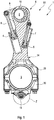
- einen Längsschnitt durch ein Beispiel eines nichterfindungsgemäßen Pleuels;
- Fig. 2
- einen vergrößerten Ausschnitt Z des Längsschnitts gemäß
Fig. 1 mit Fokus auf das Umschaltventil in einem Querschnitt; - Fig. 3
- eine nicht erfindungsemäßen Beispiel Draufsicht auf das Umchaltventil gemäß einem mit eingezeichneten Schnittebenen A-A und B-B;
- Fig. 4
- einen Längsschnitt durch das Umschaltventil in der Schnittebene A-A gemäß
Fig. 3 ; - Fig. 5
- einen weiteren Längsschnitt durch das Umschaltventil in der Schnittebene B-B gemäß
Fig. 3 ; - Fig. 6
- eine isometrische Darstellung des Umschaltventils gemäß
Fig. 3 ; - Fig. 7
- eine Seitenansicht des Umschaltventils gemäß
Fig. 3 ; - Fig. 8
- eine weitere Seitenansicht des Umschaltventils gemäß
Fig. 3 ; - Fig. 9
- eine weitere Seitenansicht des Umschaltventils gemäß
Fig. 3 mit eingezeichneter Schnittebene C-C; - Fig. 10
- einen Querschnitt durch das Umschaltventil in der Schnittebene C-C gemäß
Fig. 9 ; - Fig. 11
- eine weitere isometrische Darstellung des Umschaltventils gemäß
Fig. 3 ; - Fig. 12
- eine Draufsicht auf das Umschaltventil gemäß
Fig. 3 ; - Fig. 13
- einen Längsschnitt durch ein Ausführungsbeispiel eines erfindungsgemäßen Pleuels;
- Fig. 14
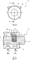
- einen vergrößerten Ausschnitt Z des Längsschnitts gemäß
Fig. 13 mit Fokus auf das Umschaltventil in einem Querschnitt; - Fig. 15
- eine isometrische Darstellung des Umschaltventils gemäß
Fig. 13 ; - Fig. 16
- eine Draufsicht auf das Umschaltventil gemäß
Fig. 13 mit eingezeichneter Schnittebene A-A; und - Fig. 17
- einen Längsschnitt durch das Umschaltventil in der Schnittebene A-A gemäß
Fig. 16 . - In den Figuren sind gleiche oder gleichartige Komponenten mit gleichen Bezugszeichen beziffert. Die Figuren zeigen lediglich Beispiele und sind nicht beschränkend zu verstehen.
- Die
Figuren 2 bis 12 zeigen verschiedene Ansichten und Schnitte eines ersten Beispiels eines Umschaltventils 11, bzw. von Einzelteilen des Umschaltventils 11 eines nichterfindungsgemäßen, inFigur 1 dargestellten Pleuels 1. - Der in
Figur 1 dargestellte Pleuel 1 weist eine Pleuelstange 34, umfassend einen Pleuelkörper 29 sowie einen Pleueldeckel 30, und eine zumindest abschnittsweise in einem Pleuellagerauge 2 angeordnete verstellbare Exzenter-Verstelleinrichtung 6 mit einem Exzenter 10 auf. Die Exzenter-Verstelleinrichtung 6 dient zur Verstellung einer effektiven Pleuelstangenlänge. Als Pleuelstangenlänge ist der Abstand einer Mittelachse eines Hublagerauges 3 zu einer Mittelachse des Pleuellagerauges 2 definiert. - Eine Verdrehung der verstellbaren Exzenter-Verstelleinrichtung 6 wird durch Einwirken von Massen- und Lastkräften der Brennkraftmaschine eingeleitet, die bei einem Arbeitstakt der Brennkraftmaschine auf die Exzenter-Verstelleinrichtung 6 wirken. Während eines Arbeitstaktes verändern sich die Wirkungsrichtungen der auf die Exzenter-Verstelleinrichtung 6 wirkenden Kräfte kontinuierlich. Die Drehbewegung oder Verstellbewegung wird durch mit Hydraulikflüssigkeit, insbesondere mit Motoröl, beaufschlagte, im Pleuel 1 integrierte Kolben 4, 5 unterstützt. Die Kolben 4, 5 verhindern dabei ein Rückstellen der Exzenter-Verstelleinrichtung 6 aufgrund variierender Kraftwirkungsrichtungen der auf die Exzenter- Verstelleinrichtung 6 wirkenden Kräfte.
- Die Kolben 4, 5 sind mittels Exzenterstangen 7, 8 beidseitig mit einem Hebel 9 der Exzenter-Verstelleinrichtung 6 wirkverbunden. Die Kolben 4, 5 sind in Hydraulikkammern verschiebbar angeordnet und über nicht gezeigte Hydraulikflüssigkeitsleitungen mit Hydraulikflüssigkeit über nicht sichtbare Rückschlagventile beaufschlagt. Die Rückschlagventile verhindern dabei ein Rückfließen der Hydraulikflüssigkeit aus den Hydraulikkammern zurück in die Hydraulikflüssigkeitsleitungen und ermöglichen ein Nachsaugen von Hydraulikflüssigkeit in die Hydraulikkammern.
Die Rückschlagventile können vorteilhafterweise in das Umschaltventil 11 beispielsweise als Kugel- oder Tellerrückschlagventile oder als Bandrückschlagventile integriert sein. Bei der Ausführung als Bandrückschlagventile kann beispielsweise eine Lagesicherung wie ein Bolzen o.ä. vorgesehen sein. Die mit den Hydraulikkammern verbundenen Hydraulikflüssigkeitsleitungen wirken alle oder wenigstens teilweise mit dem Umschaltventil 11 zusammen. In einer ersten Schaltstellung S1 des Umschaltventils 11, welche einer Stellung hoher Verdichtung des Pleuels 1 entspricht (dargestellt inFigur 1 ), ist die erste Hydraulikkammer mit einer nicht dargestellten Entlastungsleitung und in einer zweiten Schaltstellung S2 des Umschaltventils 11, welche einer Stellung niedriger Verdichtung des Pleuels 1 entspricht, die zweite Hydraulikkammer mit der Entlastungsleitung verbunden. Die Entlastungsleitung stellt dabei die Verbindung zu einer Versorgung des Pleuels 1 mit Hydraulikflüssigkeit, beispielsweise über eine Nut in dem Hublagerauge 3 des Pleuels 1 dar. - Das nachfolgend näher beschriebene Umschaltventil 11 kann aber auch für jeden anderen Pleuel für eine Brennkraftmaschine mit variabler Verdichtung vorgesehen sein, welche eine Exzenter-Verstelleinrichtung zur Verstellung einer effektiven Pleuelstangenlänge und wenigstens einer Hydraulikkammer aufweist. Beispielsweise kann die Exzenter-Verstelleinrichtung des Pleuels mit einem sogenannten Schwenkmotor-System ausgebildet sein.
- Das Umschaltventil 11 ist in
Figur 2 in einem vergrößerten Ausschnitt Z des Pleuels 1 in einem Querschnitt dargestellt.Figur 3 zeigt eine Draufsicht auf das Umschaltventil 11 mit eingezeichneten Schnittebenen A-A und B-B. Figur zeigt 4 einen Längsschnitt durch das Umschaltventil 11 in der Schnittebene A-A, währendFigur 5 einen Längsschnitt in der Schnittebene B-B darstellt. - Wie in
Figur 2 zu erkennen, ist das Umschaltventil 11 axial in einer Bohrung 23 des Pleuels 1 angeordnet, beispielsweise eingepresst. Um das Umschaltventil 11 dichtungslos in der Pleuelstange 34 bzw. einem Pleuelkörper 29 oder Pleueldeckel 30 zu montieren, kann das Ventilgehäuse 12 des Umschaltventils 11 dabei mittels einem oder mehreren Sicherungsstiften axial in der Bohrung 23 des Pleuels 1 gesichert vorgesehen sein. Der ein oder mehrere Sicherungsstifte sind in dem Schnitt inFigur 2 nicht zu entnehmen, da der Sicherungsstift in einer anderen Schnittebene angeordnet ist. - Zur Aufnahme des nicht gezeigten Sicherungsstiftes weist der Pleuel 1 Bohrungen 32 auf, welche im zweiten Ausführungsbeispiel in
Figur 14 zu erkennen sind, während das Ventilgehäuse 12 dazu korrespondierend jeweils Bohrungen 27 (inFigur 9 dargestellt) aufweist, in welche ein Sicherungsstift eingepresst vorgesehen werden kann. Die Bohrungen 32 des Pleuels 1 sind zur einfachen Herstellbarkeit beispielsweise als Durchgangsbohrungen ausgebildet. - Im Querschnitt in
Figur 2 ist das in der Bohrung 23 des Pleueldeckels 30 eingepresste Ventilgehäuse 12 des Umschaltventils mit dem im Inneren geführten Abgriffselement 13 zu erkennen. Quer zu der Achse des Ventilgehäuses 12 ist der Rastpin 18 in den Bohrungen 20, 21 angeordnet. - Im Längsschnitt des Umschaltventils 11 in
Figur 4 sind weiter die beiden Hydraulikanschlüsse 22, 24, die jeweils der Versorgung der Hydraulikkammern des Pleuels 1 auf der Massenkraftseite (MKS), bzw. Gaskraftseite (GKS) der Exzenter-Verstelleinrichtung 6 des Pleuels 1 zugeordnet sind und den Schaltstellungen S1 und S2 entsprechen. Im Querschnitt inFigur 5 sind die Entlastungsanschlüsse 26 zu erkennen, welche mit der Hydraulikversorgung P verbunden sind. - Das Umschaltventil 11 weist ein in einem Ventilgehäuse 12 angeordnetes Abgriffselement 13 auf, welches in einer axialen Richtung L (siehe
Figur 4 ) verschiebbar wahlweise in eine erste Schaltstellung S1 oder eine zweite Schaltstellung S2 verlagerbar und mittels eines federbeaufschlagten Rastelementes 14 wahlweise in der ersten oder der zweiten Schaltstellung S1, S2 arretierbar ist. Das Rastelement 14 weist dazu ein in einer Rasthülse 33 angeordnetes Federelement 15 auf. In der ersten Schaltstellung S1 ist ein erster Hydraulikanschluss 22 des Umschaltventils 11 mit einem Entlastungsanschluss 26 und in der zweiten Schaltstellung S2 ist ein zweiter Hydraulikanschluss 24 mit dem Entlastungsanschluss 26 verbunden, wie insbesondereFigur 4 zu entnehmen ist. - Das in dem Ventilgehäuse 12 angeordnete Abgriffselement 13 ist wahlweise in der ersten Schaltstellung S1 oder der zweiten Schaltstellung S2 arretierbar. Hierfür sind das Rastelement 14 und das in dem Rastelement 14 angeordnete Federelement 15 wenigstens teilweise in einer quer ausgebildeten Ausnehmung 16 des Abgriffselements 13 angeordnet. Das Ventilgehäuse 12 weist dazu in der axialen Richtung L eine axial begrenzte erste Nut 17 auf, in welcher das Rastelement 14 zur Begrenzung des Schaltweges und zur Verdrehsicherung des Abgriffselements 13 axial verschiebbar angeordnet ist. Die zumindest teilweise Anordnung des Rastelementes 14 in der Ausnehmung 16 ist von Vorteil, da die Führungslänge des beweglichen Rastelementes 14 im Vergleich zu den bekannten Umschaltventilen entscheidend vergrößert werden kann. Die Verkantungsneigung und Selbsthemmungsneigung kann verringert und ein sicheres Erreichen der Endlagen aus eigener Kraft verbessert werden. Zudem ist die Federauslegung des Federelements 15 wegen größerer Einbaulänge im Vergleich zum Stand der Technik nicht kritisch.
- Das Rastelement 14 dient zusätzlich als Anschlagelement, welches einen Verschiebeweg des Abgriffselements 13 im Ventilgehäuse 12 begrenzt. Dadurch kann das Anschlagelement als zusätzliches Bauteil entfallen. Das Rastelement 14 ist mit dem Abgriffselement 13 zusammen axial verschiebbar vorgesehen. Das Rastelement 14 wirkt mit einem Rastpin 18 zusammen, welcher im Ventilgehäuse 12 im Bereich der ersten Nut 17 angeordnet ist.
- Um das Umschaltventil 11 in den beiden Schaltstellungen S1 und S2 zu arretieren, weist das Rastelement 14 eine Rastkontur 19 auf, welche im Zusammenspiel mit dem Rastpin 18 zwei Rastpositionen für das Rastelement 14 ermöglicht. Wie
Figur 4 zu entnehmen ist, kann beim axialen Verschieben des Abgriffselements 13 das Rastelement 14 mit seiner Rastkontur 19 zu beiden Seiten des Rastpins 18 einrasten. -
Figur 6 zeigt eine isometrische Darstellung des Umschaltventils 11 gemäßFigur 3 , während in denFiguren 7, 8, 9 verschiedene Seitenansichten des Umschaltventils 11 dargestellt sind. InFigur 9 ist eine Schnittebene C-C eingezeichnet, deren Querschnitt des Umschaltventils 11 inFigur 10 dargestellt ist.Figur 11 zeigt eine weitere isometrische Darstellung des Umschaltventils 11 undFigur 12 eine Draufsicht auf das Umschaltventil 11. - Wie
Figur 6 zu entnehmen ist, weist das Ventilgehäuse 12 im Bereich der ersten Nut 17 Bohrungen 20, 21 auf, in welche der Rastpin 18 eingepresst vorgesehen ist. Auch ist der Entlastungsanschluss 26 zu erkennen. - Die Seitenansicht in
Figur 7 zeigt die Anordnung der beiden Hydraulikanschlüsse 22, 24, währendFigur 8 den Entlastungsanschluss 26 als Langloch zeigt. - Zur Aufnahme eines Sicherungsstiftes weist der Pleuel 1 Bohrungen 32 auf, wie bei dem Ausführungsbeispiel in
Figur 14 dargestellt, während das Ventilgehäuse 12 dazu korrespondierend jeweils Bohrungen 27 (inFigur 9 dargestellt) aufweist, in welche ein Sicherungsstift eingepresst vorgesehen werden kann. Die Bohrungen 32 des Pleuels 1 sind zur einfachen Herstellbarkeit beispielsweise als Durchgangsbohrungen ausgebildet. - Eine Bohrung des Pleuels 1 könnte alternativ als Sacklochbohrung ausgebildet sein, wodurch vorteilhaft Restschmutz vermieden werden kann. Ferner kann der Einpressvorgang dadurch vereinfacht werden, dass der Einpressvorgang nicht mehr bezüglich des Weges überwacht werden muss.
- In
Figur 9 ist weiter durch die Nut 17 der Rastpin 18 zu erkennen. - Den
Figuren 13 bis 17 ist ein Ausführungsbeispiel eines erfindungsgemäßen Pleuels 1 zu entnehmen, welches sich darin unterscheidet, dass der Rastpin 18 zusätzlich als Sicherungsstift dient. Der Rastpin 18 als Sicherungsstift ist dabei als Axialsicherung des Umschaltventils 11 im Pleuel 1 vorgesehen. -
Figur 13 zeigt dabei einen Längsschnitt durch den Pleuel 1, während inFigur 14 ein vergrößerter Ausschnitt Z des Längsschnitts gemäßFigur 13 mit Fokus auf das Umschaltventil 11 in einem Querschnitt dargestellt ist. -
Figur 15 zeigt eine isometrische Darstellung des Umschaltventils 11 gemäßFigur 13 . InFigur 16 ist eine Draufsicht auf das Umschaltventil 11 mit eingezeichneter Schnittebene A-A dargestellt, währendFigur 17 einen Längsschnitt durch das Umschaltventil 11 in der Schnittebene A-A zeigt. - Wie insbesondere dem vergrößerten Ausschnitt in
Figur 14 zu entnehmen ist, ist der Rastpin 18 durch den Pleueldeckel 30 und das Ventilgehäuse 12 gepresst. Dazu ist im Pleueldeckel 30 eine Bohrung 32, vorzugsweise eine Durchgangsbohrung vorgesehen, durch welche der Rastpin 18 als Sicherungselement eingeführt werden und durch Bohrungen 20, 21 im Ventilgehäuse 12 hindurchgeführt werden kann. Bei genügender Länge des Rastpins 18, kann der Rastpin 18 zu beiden Seiten über das Ventilgehäuse 12 hinausragen, sodass er als Sicherungselement in der Bohrung 32 des Pleueldeckels 30 verankert ist. Vorteilhafterweise befindet sich nur ein Pressverband in dem Ventilgehäuse 12, während der Rastpin 18 im Pleueldeckel 30 minimales Spiel hat. Dadurch erhält man an dieser Stelle keine zusätzlichen Spannungen im Ventilgehäuse 12 und Toleranzen bezüglich Konzentrizität der Bohrungen 32 im Pleueldeckel 30 sowie der Bohrungen 20, 21 im Ventilgehäuse 12 können ausgeglichen werden. - Alternativ können die Bohrungen 32 auch als Sacklochbohrungen vorgesehen sein. Die Bohrungen 32 können günstigerweise eine Spielpassung aufweisen, in welcher der ein oder mehrere Sicherungsstifte durch Umformen der Enden, beispielsweise Umbördeln, gegen Herausfallen gesichert ist.
- Für die Montage ergibt sich die Situation, dass das Umschaltventil 11 nicht mehr vormontiert werden kann, da der Rastpin 18 erst nach Einpressen des Ventilgehäuses 12 eingepresst wird. Die Montage des Rastpins 18 erfolgt also nach dem Einpressen des Ventilgehäuses 12 in die Bohrung 23 im Pleueldeckel 30. Im Pleueldeckel 30 ist daher zweckmäßigerweise mindestens eine Bohrung 31 eingebracht, durch welche das Rastelement 14 in das Ventilgehäuse 12 eingebracht werden kann. Alternativ ist eine Langlochnut denkbar.
- Als weitere alternative Ausführung kann vorgesehen sein, einen temporären Rastpin in das Ventilgehäuse 12 zu montieren, welcher nicht aus dem Ventilgehäuse 12 heraussteht und mittels des endgültigen Rastpins 18 bei dessen Montage herausgestoßen wird. Der temporäre Rastpin kann eine Presspassung, eine Übergangspassung oder eine Spielpassung haben.
- In der isometrischen Darstellung in
Figur 15 ist der länger als bei dem vorigen Ausführungsbeispiel ausgebildete Rastpin 18 zu erkennen, welcher die Nut 17 des Ventilgehäuses 12 quer durchtritt und zu beiden Seiten über das Ventilgehäuse 12 hinausragt. Ebenfalls ist der Entlastungsanschluss 26 zu erkennen. Die Länge des Rastpins 18 ist auch der Draufsicht inFigur 16 zu entnehmen. -
Figur 17 zeigt im Längsschnitt das Umschaltventil, das im Wesentlichen der Darstellung des ersten Beispiels inFigur 4 gleicht. Der Unterschied besteht darin, dass keine zusätzlichen Bohrungen 27 zur Anbringung eines zusätzlichen Sicherungsstiftes nötig sind, sodass die Herstellung des Ventilgehäuses 12 vereinfacht werden kann.
Claims (6)
- Pleuel (1) für eine Brennkraftmaschine mit variabler Verdichtung mit einer Exzenter-Verstelleinrichtung (6) im Pleuelkörper (29) zur Verstellung einer effektiven Pleuelstangenlänge, wobei ein Verstellweg der Exzenter-Verstelleinrichtung (6) mittels eines Umschaltventils (11) verstellbar ist, wobei ein Ventilgehäuse (12) des Umschaltventils (11) mittels einem oder mehreren Sicherungselementen axial in einer Bohrung (23) des Pleuels (1) gesichert vorgesehen ist und das Umschaltventil (11) ein in dem Ventilgehäuse (12) angeordnetes Abgriffselement (13) aufweist, welches wahlweise in eine erste Schaltstellung (S1) oder eine zweite Schaltstellung (S2) verlagerbar und wahlweise in der ersten oder der zweiten Schaltstellung (S1, S2) arretierbar ist, dadurch gekennzeichnet, dass das Umschaltventil (13) mittels eines federelementbeaufschlagten Rastelement (14) wahlweise in der ersten oder der zweiten Schaltstellung (S1, S2) arretierbar ist, wobei das Rastelement (14) wenigstens teilweise in einer Ausnehmung (16) des Abgriffselements (13) angeordnet mit dem Abgriffselement (13) in einer axialen Richtung (L) in einer axial begrenzten Nut (17) des Ventilgehäuses (12) verschiebbar ist und mit einem Rastpin (18) zusammenwirkt, wobei der Rastpin als Sicherungsstift zusätzlich als Axialsicherung des Umschaltventils (11) vorgesehen ist.
- Pleuel (1) nach Anspruch 1, wobei der Pleuel (1) und das Ventilgehäuse (12) Bohrungen (32, 27) aufweisen, in welche der Sicherungsstifteingepresst vorgesehen ist.
- Pleuel (1) nach Anspruch 1 oder 2, wobei das Umschaltventil (11) dichtungslos im Pleueldeckel (30) eingesetzt ist.
- Pleuel (1) nach Anspruch 1, wobei eine Bohrung (31) im Pleueldeckel (30) zur Montage des Rastelements (14) in das Ventilgehäuse (12) des Umschaltventils (11) vorgesehen ist.
- Pleuel (1) nach einem der vorhergehenden Ansprüche 2 bis 4, wobei die Bohrungen (32) als Sacklochbohrungen vorgesehen sind.
- Pleuel (1) nach einem der vorhergehenden Ansprüche 2 bis 5, wobei die Bohrungen (32) eine Spielpassung aufweisen, in welcher der Sicherungsstift durch Umformen gegen Herausfallen gesichert ist.
Applications Claiming Priority (3)
| Application Number | Priority Date | Filing Date | Title |
|---|---|---|---|
| DE102017120255 | 2017-09-04 | ||
| DE102018107108.6A DE102018107108A1 (de) | 2017-09-04 | 2018-03-26 | Umschaltventil zum Steuern eines Hydraulikflüssigkeitsstroms und Pleuel für eine Brennkraftmaschine mit variabler Verdichtung mit einem Umschaltventil |
| EP18189918.8A EP3450720A3 (de) | 2017-09-04 | 2018-08-21 | Umschaltventil zum steuern eines hydraulikflüssigkeitsstroms und pleuel für eine brennkraftmaschine mit variabler verdichtung mit einem umschaltventil |
Related Parent Applications (2)
| Application Number | Title | Priority Date | Filing Date |
|---|---|---|---|
| EP18189918.8A Division-Into EP3450720A3 (de) | 2017-09-04 | 2018-08-21 | Umschaltventil zum steuern eines hydraulikflüssigkeitsstroms und pleuel für eine brennkraftmaschine mit variabler verdichtung mit einem umschaltventil |
| EP18189918.8A Division EP3450720A3 (de) | 2017-09-04 | 2018-08-21 | Umschaltventil zum steuern eines hydraulikflüssigkeitsstroms und pleuel für eine brennkraftmaschine mit variabler verdichtung mit einem umschaltventil |
Publications (2)
| Publication Number | Publication Date |
|---|---|
| EP3502436A1 EP3502436A1 (de) | 2019-06-26 |
| EP3502436B1 true EP3502436B1 (de) | 2020-11-04 |
Family
ID=63350398
Family Applications (2)
| Application Number | Title | Priority Date | Filing Date |
|---|---|---|---|
| EP19150637.7A Not-in-force EP3502436B1 (de) | 2017-09-04 | 2018-08-21 | Pleuel für eine brennkraftmaschine mit variabler verdichtung mit einem umschaltventil |
| EP18189918.8A Withdrawn EP3450720A3 (de) | 2017-09-04 | 2018-08-21 | Umschaltventil zum steuern eines hydraulikflüssigkeitsstroms und pleuel für eine brennkraftmaschine mit variabler verdichtung mit einem umschaltventil |
Family Applications After (1)
| Application Number | Title | Priority Date | Filing Date |
|---|---|---|---|
| EP18189918.8A Withdrawn EP3450720A3 (de) | 2017-09-04 | 2018-08-21 | Umschaltventil zum steuern eines hydraulikflüssigkeitsstroms und pleuel für eine brennkraftmaschine mit variabler verdichtung mit einem umschaltventil |
Country Status (1)
| Country | Link |
|---|---|
| EP (2) | EP3502436B1 (de) |
Families Citing this family (1)
| Publication number | Priority date | Publication date | Assignee | Title |
|---|---|---|---|---|
| DE102019121107A1 (de) * | 2019-08-05 | 2021-02-11 | ECO Holding 1 GmbH | Pleuel für eine Brennkraftmaschine mit variabler Verdichtung |
Family Cites Families (10)
| Publication number | Priority date | Publication date | Assignee | Title |
|---|---|---|---|---|
| DE102012112461A1 (de) | 2012-12-18 | 2014-06-18 | Dr. Ing. H.C. F. Porsche Aktiengesellschaft | Umschaltventil und Verbrennungsmotor mit einem derartigen Umschaltventil |
| DE102013206513B4 (de) * | 2013-04-12 | 2024-06-20 | Dr. Ing. H.C. F. Porsche Aktiengesellschaft | Umschaltventil und Verbrennungsmotor mit einem solchen Umschaltventil |
| DE102013105389B4 (de) * | 2013-05-27 | 2021-12-23 | Dr. Ing. H.C. F. Porsche Aktiengesellschaft | Umschaltventil und Verbrennungsmotor mit einem solchen Umschaltventil |
| DE102015100662A1 (de) * | 2014-12-19 | 2016-06-23 | Hilite Germany Gmbh | Hydraulikventil zum Schalten eines Stellkolbens eines Pleuels |
| DE102015202051A1 (de) * | 2015-02-05 | 2016-08-11 | Schaeffler Technologies AG & Co. KG | Umschaltventil |
| DE102015202056A1 (de) * | 2015-02-05 | 2016-08-11 | Schaeffler Technologies AG & Co. KG | Ventilgehäuse für ein bivalentes Schaltventil |
| DE102015202065A1 (de) * | 2015-02-05 | 2016-08-11 | Schaeffler Technologies AG & Co. KG | Umschaltventil mit Rücksetzfunktion für einen Verbrennungsmotor |
| DE102015203378A1 (de) * | 2015-02-25 | 2016-08-25 | Fev Gmbh | Verbrennungskraftmaschine mit einstellbarem variablen Verdichtungsverhältnis und einem Schaltmodul |
| DE102015203417B4 (de) * | 2015-02-26 | 2016-09-15 | Schaeffler Technologies AG & Co. KG | Schaltventil |
| DE102015111175A1 (de) * | 2015-03-26 | 2016-09-29 | Hilite Germany Gmbh | Hydraulikventil und Pleuel mit einem Hydraulikventil |
-
2018
- 2018-08-21 EP EP19150637.7A patent/EP3502436B1/de not_active Not-in-force
- 2018-08-21 EP EP18189918.8A patent/EP3450720A3/de not_active Withdrawn
Non-Patent Citations (1)
| Title |
|---|
| None * |
Also Published As
| Publication number | Publication date |
|---|---|
| EP3450720A3 (de) | 2019-04-24 |
| EP3502436A1 (de) | 2019-06-26 |
| EP3450720A2 (de) | 2019-03-06 |
Similar Documents
| Publication | Publication Date | Title |
|---|---|---|
| EP2764229B1 (de) | Kolbenanordnung für einen ein veränderbares kompressionsverhältnis aufweisenden brennraum einer verbrennungskraftmaschine | |
| AT518848B1 (de) | Pleuel mit verstellbarer Pleuellänge mit mechanischer Betätigung | |
| EP2764228B1 (de) | Verfahren zum variablen einstellen eines verdichtungsverhältnisses eines brennraums einer verbrennungskraftmaschine | |
| WO2018007534A1 (de) | Pleuel mit verstellbarer pleuellänge mit mechanischer betätigung | |
| DE102017121443A1 (de) | Rückschlagventil für einen Pleuel einer Brennkraftmaschine mit variabler Verdichtung sowie Pleuel mit einem derartigen Rückschlagventil | |
| DE102011111816A1 (de) | Vorrichtung mit Exzenter-Kolbenbolzen zur Erzielung eines variablen Verdichtungsverhältnisses in einem Hubkolbenmotor | |
| EP3464851B1 (de) | Umschaltventil zum steuern eines hydraulikflüssigkeitsstroms und pleuel für eine brennkraftmaschine mit variabler verdichtung mit einem umschaltventil | |
| AT519652B1 (de) | Dichtungsvorrichtung und Hydraulikkolben mit Dichtungsvorrichtung | |
| DE10235852A1 (de) | Pleuelstange für eine Brennkraftmaschine mit variabler Verdichtung und Verfahren zum Zusammenbau der Pleuelstange | |
| DE102017121630A1 (de) | Pleuel für eine Brennkraftmaschine mit variabler Verdichtung | |
| EP3502436B1 (de) | Pleuel für eine brennkraftmaschine mit variabler verdichtung mit einem umschaltventil | |
| WO2016169670A1 (de) | Einleger und pleuel für eine variable verdichtung einer brennkraftmaschine | |
| DE102018107108A1 (de) | Umschaltventil zum Steuern eines Hydraulikflüssigkeitsstroms und Pleuel für eine Brennkraftmaschine mit variabler Verdichtung mit einem Umschaltventil | |
| EP3404232B1 (de) | Pleuel für eine brennkraftmaschine mit variabler verdichtung | |
| EP3361069B1 (de) | Pleuel einer brennkraftmaschine mit variabler verdichtung mit einem rückschlagventil | |
| EP3085921B1 (de) | Pleuel mit einem umschaltventil | |
| EP3364010B1 (de) | Pleuel für eine brennkraftmaschine mit variabler verdichtung | |
| DE102017107719A1 (de) | Hydraulikventil zum Einstellen eines Hydraulikflüssigkeitsstroms eines Pleuels für eine Brennkraftmaschine mit variabler Verdichtung | |
| DE102006044294B3 (de) | Radialkolbenpumpe | |
| EP3546722B1 (de) | Pleuel für eine brennkraftmaschine mit variabler verdichtung | |
| AT524567B1 (de) | Längenverstellbare Pleuelstange mit kompaktem Ablassventil | |
| AT522162B1 (de) | Montageverfahren eines gehäusefesten Pleuelteils einer längenverstellbaren Pleuelstange | |
| DE102019101269B3 (de) | Exzenterverstelleinrichtung und längenverstellbare Pleuelstange für eine Verbrennungskraftmaschine | |
| DE102017107706A1 (de) | Längenverstellbare Pleuelstange mit einer Zylinder-Kolben-Einheit mit Verdrehsicherung | |
| DE102020109088A1 (de) | Pleuel für eine Brennkraftmaschine mit variabler Verdichtung mit einem Umschaltventil |
Legal Events
| Date | Code | Title | Description |
|---|---|---|---|
| PUAI | Public reference made under article 153(3) epc to a published international application that has entered the european phase |
Free format text: ORIGINAL CODE: 0009012 |
|
| STAA | Information on the status of an ep patent application or granted ep patent |
Free format text: STATUS: THE APPLICATION HAS BEEN PUBLISHED |
|
| AC | Divisional application: reference to earlier application |
Ref document number: 3450720 Country of ref document: EP Kind code of ref document: P |
|
| AK | Designated contracting states |
Kind code of ref document: A1 Designated state(s): AL AT BE BG CH CY CZ DE DK EE ES FI FR GB GR HR HU IE IS IT LI LT LU LV MC MK MT NL NO PL PT RO RS SE SI SK SM TR |
|
| AX | Request for extension of the european patent |
Extension state: BA ME |
|
| STAA | Information on the status of an ep patent application or granted ep patent |
Free format text: STATUS: REQUEST FOR EXAMINATION WAS MADE |
|
| 17P | Request for examination filed |
Effective date: 20190715 |
|
| RBV | Designated contracting states (corrected) |
Designated state(s): AL AT BE BG CH CY CZ DE DK EE ES FI FR GB GR HR HU IE IS IT LI LT LU LV MC MK MT NL NO PL PT RO RS SE SI SK SM TR |
|
| GRAP | Despatch of communication of intention to grant a patent |
Free format text: ORIGINAL CODE: EPIDOSNIGR1 |
|
| STAA | Information on the status of an ep patent application or granted ep patent |
Free format text: STATUS: GRANT OF PATENT IS INTENDED |
|
| GRAS | Grant fee paid |
Free format text: ORIGINAL CODE: EPIDOSNIGR3 |
|
| INTG | Intention to grant announced |
Effective date: 20200630 |
|
| GRAA | (expected) grant |
Free format text: ORIGINAL CODE: 0009210 |
|
| STAA | Information on the status of an ep patent application or granted ep patent |
Free format text: STATUS: THE PATENT HAS BEEN GRANTED |
|
| AC | Divisional application: reference to earlier application |
Ref document number: 3450720 Country of ref document: EP Kind code of ref document: P |
|
| AK | Designated contracting states |
Kind code of ref document: B1 Designated state(s): AL AT BE BG CH CY CZ DE DK EE ES FI FR GB GR HR HU IE IS IT LI LT LU LV MC MK MT NL NO PL PT RO RS SE SI SK SM TR |
|
| REG | Reference to a national code |
Ref country code: GB Ref legal event code: FG4D Free format text: NOT ENGLISH |
|
| REG | Reference to a national code |
Ref country code: CH Ref legal event code: EP |
|
| REG | Reference to a national code |
Ref country code: AT Ref legal event code: REF Ref document number: 1331094 Country of ref document: AT Kind code of ref document: T Effective date: 20201115 |
|
| REG | Reference to a national code |
Ref country code: DE Ref legal event code: R096 Ref document number: 502018002942 Country of ref document: DE |
|
| REG | Reference to a national code |
Ref country code: IE Ref legal event code: FG4D Free format text: LANGUAGE OF EP DOCUMENT: GERMAN |
|
| REG | Reference to a national code |
Ref country code: NL Ref legal event code: MP Effective date: 20201104 |
|
| PG25 | Lapsed in a contracting state [announced via postgrant information from national office to epo] |
Ref country code: NO Free format text: LAPSE BECAUSE OF FAILURE TO SUBMIT A TRANSLATION OF THE DESCRIPTION OR TO PAY THE FEE WITHIN THE PRESCRIBED TIME-LIMIT Effective date: 20210204 Ref country code: GR Free format text: LAPSE BECAUSE OF FAILURE TO SUBMIT A TRANSLATION OF THE DESCRIPTION OR TO PAY THE FEE WITHIN THE PRESCRIBED TIME-LIMIT Effective date: 20210205 Ref country code: PT Free format text: LAPSE BECAUSE OF FAILURE TO SUBMIT A TRANSLATION OF THE DESCRIPTION OR TO PAY THE FEE WITHIN THE PRESCRIBED TIME-LIMIT Effective date: 20210304 Ref country code: RS Free format text: LAPSE BECAUSE OF FAILURE TO SUBMIT A TRANSLATION OF THE DESCRIPTION OR TO PAY THE FEE WITHIN THE PRESCRIBED TIME-LIMIT Effective date: 20201104 Ref country code: FI Free format text: LAPSE BECAUSE OF FAILURE TO SUBMIT A TRANSLATION OF THE DESCRIPTION OR TO PAY THE FEE WITHIN THE PRESCRIBED TIME-LIMIT Effective date: 20201104 |
|
| PG25 | Lapsed in a contracting state [announced via postgrant information from national office to epo] |
Ref country code: ES Free format text: LAPSE BECAUSE OF FAILURE TO SUBMIT A TRANSLATION OF THE DESCRIPTION OR TO PAY THE FEE WITHIN THE PRESCRIBED TIME-LIMIT Effective date: 20201104 Ref country code: SE Free format text: LAPSE BECAUSE OF FAILURE TO SUBMIT A TRANSLATION OF THE DESCRIPTION OR TO PAY THE FEE WITHIN THE PRESCRIBED TIME-LIMIT Effective date: 20201104 Ref country code: IS Free format text: LAPSE BECAUSE OF FAILURE TO SUBMIT A TRANSLATION OF THE DESCRIPTION OR TO PAY THE FEE WITHIN THE PRESCRIBED TIME-LIMIT Effective date: 20210304 Ref country code: LV Free format text: LAPSE BECAUSE OF FAILURE TO SUBMIT A TRANSLATION OF THE DESCRIPTION OR TO PAY THE FEE WITHIN THE PRESCRIBED TIME-LIMIT Effective date: 20201104 Ref country code: PL Free format text: LAPSE BECAUSE OF FAILURE TO SUBMIT A TRANSLATION OF THE DESCRIPTION OR TO PAY THE FEE WITHIN THE PRESCRIBED TIME-LIMIT Effective date: 20201104 Ref country code: BG Free format text: LAPSE BECAUSE OF FAILURE TO SUBMIT A TRANSLATION OF THE DESCRIPTION OR TO PAY THE FEE WITHIN THE PRESCRIBED TIME-LIMIT Effective date: 20210204 |
|
| REG | Reference to a national code |
Ref country code: LT Ref legal event code: MG9D |
|
| PG25 | Lapsed in a contracting state [announced via postgrant information from national office to epo] |
Ref country code: HR Free format text: LAPSE BECAUSE OF FAILURE TO SUBMIT A TRANSLATION OF THE DESCRIPTION OR TO PAY THE FEE WITHIN THE PRESCRIBED TIME-LIMIT Effective date: 20201104 |
|
| PG25 | Lapsed in a contracting state [announced via postgrant information from national office to epo] |
Ref country code: LT Free format text: LAPSE BECAUSE OF FAILURE TO SUBMIT A TRANSLATION OF THE DESCRIPTION OR TO PAY THE FEE WITHIN THE PRESCRIBED TIME-LIMIT Effective date: 20201104 Ref country code: RO Free format text: LAPSE BECAUSE OF FAILURE TO SUBMIT A TRANSLATION OF THE DESCRIPTION OR TO PAY THE FEE WITHIN THE PRESCRIBED TIME-LIMIT Effective date: 20201104 Ref country code: SM Free format text: LAPSE BECAUSE OF FAILURE TO SUBMIT A TRANSLATION OF THE DESCRIPTION OR TO PAY THE FEE WITHIN THE PRESCRIBED TIME-LIMIT Effective date: 20201104 Ref country code: SK Free format text: LAPSE BECAUSE OF FAILURE TO SUBMIT A TRANSLATION OF THE DESCRIPTION OR TO PAY THE FEE WITHIN THE PRESCRIBED TIME-LIMIT Effective date: 20201104 Ref country code: CZ Free format text: LAPSE BECAUSE OF FAILURE TO SUBMIT A TRANSLATION OF THE DESCRIPTION OR TO PAY THE FEE WITHIN THE PRESCRIBED TIME-LIMIT Effective date: 20201104 Ref country code: EE Free format text: LAPSE BECAUSE OF FAILURE TO SUBMIT A TRANSLATION OF THE DESCRIPTION OR TO PAY THE FEE WITHIN THE PRESCRIBED TIME-LIMIT Effective date: 20201104 |
|
| REG | Reference to a national code |
Ref country code: DE Ref legal event code: R097 Ref document number: 502018002942 Country of ref document: DE |
|
| PG25 | Lapsed in a contracting state [announced via postgrant information from national office to epo] |
Ref country code: DK Free format text: LAPSE BECAUSE OF FAILURE TO SUBMIT A TRANSLATION OF THE DESCRIPTION OR TO PAY THE FEE WITHIN THE PRESCRIBED TIME-LIMIT Effective date: 20201104 |
|
| PLBE | No opposition filed within time limit |
Free format text: ORIGINAL CODE: 0009261 |
|
| STAA | Information on the status of an ep patent application or granted ep patent |
Free format text: STATUS: NO OPPOSITION FILED WITHIN TIME LIMIT |
|
| 26N | No opposition filed |
Effective date: 20210805 |
|
| PG25 | Lapsed in a contracting state [announced via postgrant information from national office to epo] |
Ref country code: NL Free format text: LAPSE BECAUSE OF FAILURE TO SUBMIT A TRANSLATION OF THE DESCRIPTION OR TO PAY THE FEE WITHIN THE PRESCRIBED TIME-LIMIT Effective date: 20201104 Ref country code: AL Free format text: LAPSE BECAUSE OF FAILURE TO SUBMIT A TRANSLATION OF THE DESCRIPTION OR TO PAY THE FEE WITHIN THE PRESCRIBED TIME-LIMIT Effective date: 20201104 Ref country code: IT Free format text: LAPSE BECAUSE OF FAILURE TO SUBMIT A TRANSLATION OF THE DESCRIPTION OR TO PAY THE FEE WITHIN THE PRESCRIBED TIME-LIMIT Effective date: 20201104 |
|
| PGFP | Annual fee paid to national office [announced via postgrant information from national office to epo] |
Ref country code: FR Payment date: 20210819 Year of fee payment: 4 |
|
| PG25 | Lapsed in a contracting state [announced via postgrant information from national office to epo] |
Ref country code: SI Free format text: LAPSE BECAUSE OF FAILURE TO SUBMIT A TRANSLATION OF THE DESCRIPTION OR TO PAY THE FEE WITHIN THE PRESCRIBED TIME-LIMIT Effective date: 20201104 |
|
| REG | Reference to a national code |
Ref country code: CH Ref legal event code: PL |
|
| PG25 | Lapsed in a contracting state [announced via postgrant information from national office to epo] |
Ref country code: MC Free format text: LAPSE BECAUSE OF FAILURE TO SUBMIT A TRANSLATION OF THE DESCRIPTION OR TO PAY THE FEE WITHIN THE PRESCRIBED TIME-LIMIT Effective date: 20201104 |
|
| REG | Reference to a national code |
Ref country code: BE Ref legal event code: MM Effective date: 20210831 |
|
| PG25 | Lapsed in a contracting state [announced via postgrant information from national office to epo] |
Ref country code: LI Free format text: LAPSE BECAUSE OF NON-PAYMENT OF DUE FEES Effective date: 20210831 Ref country code: CH Free format text: LAPSE BECAUSE OF NON-PAYMENT OF DUE FEES Effective date: 20210831 |
|
| PG25 | Lapsed in a contracting state [announced via postgrant information from national office to epo] |
Ref country code: IS Free format text: LAPSE BECAUSE OF FAILURE TO SUBMIT A TRANSLATION OF THE DESCRIPTION OR TO PAY THE FEE WITHIN THE PRESCRIBED TIME-LIMIT Effective date: 20210304 Ref country code: LU Free format text: LAPSE BECAUSE OF NON-PAYMENT OF DUE FEES Effective date: 20210821 |
|
| PG25 | Lapsed in a contracting state [announced via postgrant information from national office to epo] |
Ref country code: IE Free format text: LAPSE BECAUSE OF NON-PAYMENT OF DUE FEES Effective date: 20210821 Ref country code: BE Free format text: LAPSE BECAUSE OF NON-PAYMENT OF DUE FEES Effective date: 20210831 |
|
| GBPC | Gb: european patent ceased through non-payment of renewal fee |
Effective date: 20220821 |
|
| P01 | Opt-out of the competence of the unified patent court (upc) registered |
Effective date: 20230515 |
|
| PG25 | Lapsed in a contracting state [announced via postgrant information from national office to epo] |
Ref country code: CY Free format text: LAPSE BECAUSE OF FAILURE TO SUBMIT A TRANSLATION OF THE DESCRIPTION OR TO PAY THE FEE WITHIN THE PRESCRIBED TIME-LIMIT Effective date: 20201104 |
|
| PG25 | Lapsed in a contracting state [announced via postgrant information from national office to epo] |
Ref country code: HU Free format text: LAPSE BECAUSE OF FAILURE TO SUBMIT A TRANSLATION OF THE DESCRIPTION OR TO PAY THE FEE WITHIN THE PRESCRIBED TIME-LIMIT; INVALID AB INITIO Effective date: 20180821 Ref country code: FR Free format text: LAPSE BECAUSE OF NON-PAYMENT OF DUE FEES Effective date: 20220831 |
|
| PG25 | Lapsed in a contracting state [announced via postgrant information from national office to epo] |
Ref country code: GB Free format text: LAPSE BECAUSE OF NON-PAYMENT OF DUE FEES Effective date: 20220821 |
|
| PG25 | Lapsed in a contracting state [announced via postgrant information from national office to epo] |
Ref country code: MK Free format text: LAPSE BECAUSE OF FAILURE TO SUBMIT A TRANSLATION OF THE DESCRIPTION OR TO PAY THE FEE WITHIN THE PRESCRIBED TIME-LIMIT Effective date: 20201104 |
|
| PG25 | Lapsed in a contracting state [announced via postgrant information from national office to epo] |
Ref country code: MT Free format text: LAPSE BECAUSE OF FAILURE TO SUBMIT A TRANSLATION OF THE DESCRIPTION OR TO PAY THE FEE WITHIN THE PRESCRIBED TIME-LIMIT Effective date: 20201104 |
|
| PGFP | Annual fee paid to national office [announced via postgrant information from national office to epo] |
Ref country code: DE Payment date: 20240821 Year of fee payment: 7 |
|
| REG | Reference to a national code |
Ref country code: AT Ref legal event code: MM01 Ref document number: 1331094 Country of ref document: AT Kind code of ref document: T Effective date: 20230821 |
|
| PG25 | Lapsed in a contracting state [announced via postgrant information from national office to epo] |
Ref country code: AT Free format text: LAPSE BECAUSE OF NON-PAYMENT OF DUE FEES Effective date: 20230821 |
|
| PG25 | Lapsed in a contracting state [announced via postgrant information from national office to epo] |
Ref country code: AT Free format text: LAPSE BECAUSE OF NON-PAYMENT OF DUE FEES Effective date: 20230821 |
|
| PG25 | Lapsed in a contracting state [announced via postgrant information from national office to epo] |
Ref country code: TR Free format text: LAPSE BECAUSE OF FAILURE TO SUBMIT A TRANSLATION OF THE DESCRIPTION OR TO PAY THE FEE WITHIN THE PRESCRIBED TIME-LIMIT Effective date: 20201104 |
|
| REG | Reference to a national code |
Ref country code: DE Ref legal event code: R119 Ref document number: 502018002942 Country of ref document: DE |
|
| PGFP | Annual fee paid to national office [announced via postgrant information from national office to epo] |
Ref country code: AT Payment date: 20260410 Year of fee payment: 5 |