EP3502329A1 - Woven fabric with optical fibres - Google Patents
Woven fabric with optical fibres Download PDFInfo
- Publication number
- EP3502329A1 EP3502329A1 EP18212969.2A EP18212969A EP3502329A1 EP 3502329 A1 EP3502329 A1 EP 3502329A1 EP 18212969 A EP18212969 A EP 18212969A EP 3502329 A1 EP3502329 A1 EP 3502329A1
- Authority
- EP
- European Patent Office
- Prior art keywords
- fiber
- region
- woven fabric
- layer
- fibers
- Prior art date
- Legal status (The legal status is an assumption and is not a legal conclusion. Google has not performed a legal analysis and makes no representation as to the accuracy of the status listed.)
- Granted
Links
Images






Classifications
-
- D—TEXTILES; PAPER
- D03—WEAVING
- D03D—WOVEN FABRICS; METHODS OF WEAVING; LOOMS
- D03D15/00—Woven fabrics characterised by the material, structure or properties of the fibres, filaments, yarns, threads or other warp or weft elements used
-
- B—PERFORMING OPERATIONS; TRANSPORTING
- B32—LAYERED PRODUCTS
- B32B—LAYERED PRODUCTS, i.e. PRODUCTS BUILT-UP OF STRATA OF FLAT OR NON-FLAT, e.g. CELLULAR OR HONEYCOMB, FORM
- B32B5/00—Layered products characterised by the non- homogeneity or physical structure, i.e. comprising a fibrous, filamentary, particulate or foam layer; Layered products characterised by having a layer differing constitutionally or physically in different parts
- B32B5/02—Layered products characterised by the non- homogeneity or physical structure, i.e. comprising a fibrous, filamentary, particulate or foam layer; Layered products characterised by having a layer differing constitutionally or physically in different parts characterised by structural features of a fibrous or filamentary layer
- B32B5/024—Woven fabric
-
- B—PERFORMING OPERATIONS; TRANSPORTING
- B32—LAYERED PRODUCTS
- B32B—LAYERED PRODUCTS, i.e. PRODUCTS BUILT-UP OF STRATA OF FLAT OR NON-FLAT, e.g. CELLULAR OR HONEYCOMB, FORM
- B32B5/00—Layered products characterised by the non- homogeneity or physical structure, i.e. comprising a fibrous, filamentary, particulate or foam layer; Layered products characterised by having a layer differing constitutionally or physically in different parts
- B32B5/22—Layered products characterised by the non- homogeneity or physical structure, i.e. comprising a fibrous, filamentary, particulate or foam layer; Layered products characterised by having a layer differing constitutionally or physically in different parts characterised by the presence of two or more layers which are next to each other and are fibrous, filamentary, formed of particles or foamed
- B32B5/24—Layered products characterised by the non- homogeneity or physical structure, i.e. comprising a fibrous, filamentary, particulate or foam layer; Layered products characterised by having a layer differing constitutionally or physically in different parts characterised by the presence of two or more layers which are next to each other and are fibrous, filamentary, formed of particles or foamed one layer being a fibrous or filamentary layer
- B32B5/26—Layered products characterised by the non- homogeneity or physical structure, i.e. comprising a fibrous, filamentary, particulate or foam layer; Layered products characterised by having a layer differing constitutionally or physically in different parts characterised by the presence of two or more layers which are next to each other and are fibrous, filamentary, formed of particles or foamed one layer being a fibrous or filamentary layer another layer next to it also being fibrous or filamentary
-
- D—TEXTILES; PAPER
- D03—WEAVING
- D03D—WOVEN FABRICS; METHODS OF WEAVING; LOOMS
- D03D1/00—Woven fabrics designed to make specified articles
-
- D—TEXTILES; PAPER
- D03—WEAVING
- D03D—WOVEN FABRICS; METHODS OF WEAVING; LOOMS
- D03D1/00—Woven fabrics designed to make specified articles
- D03D1/0088—Fabrics having an electronic function
-
- D—TEXTILES; PAPER
- D03—WEAVING
- D03D—WOVEN FABRICS; METHODS OF WEAVING; LOOMS
- D03D11/00—Double or multi-ply fabrics not otherwise provided for
-
- D—TEXTILES; PAPER
- D03—WEAVING
- D03D—WOVEN FABRICS; METHODS OF WEAVING; LOOMS
- D03D11/00—Double or multi-ply fabrics not otherwise provided for
- D03D11/02—Fabrics formed with pockets, tubes, loops, folds, tucks or flaps
-
- D—TEXTILES; PAPER
- D03—WEAVING
- D03D—WOVEN FABRICS; METHODS OF WEAVING; LOOMS
- D03D15/00—Woven fabrics characterised by the material, structure or properties of the fibres, filaments, yarns, threads or other warp or weft elements used
- D03D15/20—Woven fabrics characterised by the material, structure or properties of the fibres, filaments, yarns, threads or other warp or weft elements used characterised by the material of the fibres or filaments constituting the yarns or threads
- D03D15/283—Woven fabrics characterised by the material, structure or properties of the fibres, filaments, yarns, threads or other warp or weft elements used characterised by the material of the fibres or filaments constituting the yarns or threads synthetic polymer-based, e.g. polyamide or polyester fibres
-
- D—TEXTILES; PAPER
- D03—WEAVING
- D03D—WOVEN FABRICS; METHODS OF WEAVING; LOOMS
- D03D15/00—Woven fabrics characterised by the material, structure or properties of the fibres, filaments, yarns, threads or other warp or weft elements used
- D03D15/50—Woven fabrics characterised by the material, structure or properties of the fibres, filaments, yarns, threads or other warp or weft elements used characterised by the properties of the yarns or threads
- D03D15/547—Woven fabrics characterised by the material, structure or properties of the fibres, filaments, yarns, threads or other warp or weft elements used characterised by the properties of the yarns or threads with optical functions other than colour, e.g. comprising light-emitting fibres
-
- D—TEXTILES; PAPER
- D03—WEAVING
- D03D—WOVEN FABRICS; METHODS OF WEAVING; LOOMS
- D03D19/00—Gauze or leno-woven fabrics
-
- D—TEXTILES; PAPER
- D03—WEAVING
- D03D—WOVEN FABRICS; METHODS OF WEAVING; LOOMS
- D03D25/00—Woven fabrics not otherwise provided for
-
- G—PHYSICS
- G02—OPTICS
- G02B—OPTICAL ELEMENTS, SYSTEMS OR APPARATUS
- G02B6/00—Light guides; Structural details of arrangements comprising light guides and other optical elements, e.g. couplings
- G02B6/0001—Light guides; Structural details of arrangements comprising light guides and other optical elements, e.g. couplings specially adapted for lighting devices or systems
- G02B6/0005—Light guides; Structural details of arrangements comprising light guides and other optical elements, e.g. couplings specially adapted for lighting devices or systems the light guides being of the fibre type
- G02B6/001—Light guides; Structural details of arrangements comprising light guides and other optical elements, e.g. couplings specially adapted for lighting devices or systems the light guides being of the fibre type the light being emitted along at least a portion of the lateral surface of the fibre
-
- B—PERFORMING OPERATIONS; TRANSPORTING
- B32—LAYERED PRODUCTS
- B32B—LAYERED PRODUCTS, i.e. PRODUCTS BUILT-UP OF STRATA OF FLAT OR NON-FLAT, e.g. CELLULAR OR HONEYCOMB, FORM
- B32B2551/00—Optical elements
-
- D—TEXTILES; PAPER
- D10—INDEXING SCHEME ASSOCIATED WITH SUBLASSES OF SECTION D, RELATING TO TEXTILES
- D10B—INDEXING SCHEME ASSOCIATED WITH SUBLASSES OF SECTION D, RELATING TO TEXTILES
- D10B2401/00—Physical properties
- D10B2401/20—Physical properties optical
-
- D—TEXTILES; PAPER
- D10—INDEXING SCHEME ASSOCIATED WITH SUBLASSES OF SECTION D, RELATING TO TEXTILES
- D10B—INDEXING SCHEME ASSOCIATED WITH SUBLASSES OF SECTION D, RELATING TO TEXTILES
- D10B2505/00—Industrial
- D10B2505/08—Upholstery, mattresses
-
- D—TEXTILES; PAPER
- D10—INDEXING SCHEME ASSOCIATED WITH SUBLASSES OF SECTION D, RELATING TO TEXTILES
- D10B—INDEXING SCHEME ASSOCIATED WITH SUBLASSES OF SECTION D, RELATING TO TEXTILES
- D10B2505/00—Industrial
- D10B2505/12—Vehicles
Definitions
- the present disclosure relates to a woven fabric, and particularly to a woven fabric in which an optical fiber is put in a part of the woven fabric.
- Patent Document 1 discloses a woven fabric in which an optical fiber is embedded in a part of the woven fabric.
- the optical fiber is connected to a light source, and light is emitted from the optical fiber.
- the woven fabric becomes a vivid woven fabric.
- the present disclosure has been made in view of these problems, and an object thereof is to provide an optical fiber woven fabric and a manufacturing method thereof, in which optical fibers may be easily extracted from the optical fiber woven fabric, and various types of light sources in various colors are freely combined according to a designated type or a coloration in a designated region, so that various types of complicated light emissions in various colors may be expressed.
- a woven fabric including: a first region where a first fiber as an optical fiber is woven with a second fiber as a non-optical fiber; a second region adjacent to the first region, in which the first fiber is not woven; and a third region adjacent to the second region, in which the first fiber is connected to a light source.
- the position of the optical fiber may be fixed within the woven fabric.
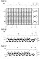
- FIG. 1A is a plan view of a woven fabric 100 according to a first exemplary embodiment.
- FIG. 1B is a cross-sectional view of a portion of the woven fabric 100 according to the first exemplary embodiment in which a first fiber 11 is present on a front portion.
- FIG. 1C is a cross-sectional view of a portion of the woven fabric 100 according to the first exemplary embodiment in which a fourth fiber 14 is present on a rear portion.
- the woven fabric 100 has a first region 51 to a sixth region 56.
- the first fiber 11, the fourth fiber 14, and a second fiber 12 are woven as wefts and warps.
- the second region 52 is a region where the first fiber 11 is present alone. It is desirable that the first fiber 11 is not fixed. The portion of the second region 52 may be folded back so that the woven fabric 100 may be mounted in, for example, an automobile. It is desirable that another fiber, such as the fourth fiber 14, is present for protection in the upper layer of the first fiber 11.
- the third region 53 is a region where the first fiber 11 is connected to a light source 20.
- the first fiber 11 has a margin (degree of freedom) in the portion of the second region 52.
- the fourth region 54, the fifth region 55, and the sixth region 56 are partitioned regions for the light sources 20, respectively.
- a seventh region 57 is a front surface layer of the woven fabric 100.
- An eighth region 58 is a back surface layer or an internal layer of the woven fabric 100.
- the first fiber 11 is an optical fiber. It is desirable that the optical fiber is made of a resin from the viewpoint of a weaving property. Specifically, for example, (1) an optical fiber in which a core and a clad which do not allow total reflection but are correlated with a refractive index are combined, or (2) an optical fiber in which a core material is blended with a light scattering material may be used.
- the above (1) is a side emission-type optical fiber using a phenomenon in which light guided inside the core is not totally reflected between the core and the clad, and leaks.
- the above (2) is a side emission-type optical fiber that has a structure in which light is not totally reflected at an interface between a core and a clad due to blending with the scattering material, and scattered light leaks from the side surface of the optical fiber.
- a side emission-type optical fiber having a configuration other than these may be employed.
- these side emission-type optical fibers only one type may be used, or two or more types may be used in combination.
- the diameter of the optical fiber is not particularly limited, but, from the viewpoint of suitably obtaining a weaving property, for example, the diameter may be 0.01 mm or more and 2.0 mm or less, preferably may be 0.05 mm or more and 1.5 mm or less, and more preferably 0.1 mm or more and 1.0 mm or less.
- the ratio is not limited, but is generally 10% or more, preferably 10% or more and 90% or less, more preferably 20% or more and 80% or less, and most preferably 30% or more and 70% or less.
- a part of the first fibers 11 may be the following non-light guiding yarns.
- Optical fibers in the following exemplary embodiments are also the same as those described above.
- the second fiber 12 and the fourth fiber 14 are non-conductive fibers, and are non-light guiding yarns, which are yarns not having a light guiding property unlike the optical fiber.
- Materials constituting the second fiber 12 and the fourth fiber 14 are not limited, and may be natural fibers or synthetic fibers.
- a synthetic fiber as the constituent resins, a polyamide-based resin such as nylon 6 and nylon 66, a polyester-based resin such as polyethyleneterephthalate, polybutyleneterephthalate, and polytrimethyleneterephthalate, a polyolefin-based resin such as polypropylene, and a polyacryl-based resin may be exemplified. As these, only one type may be used, or two or more types may be used in combination.
- the fineness of the second fiber 12 and the fourth fiber 14 is not particularly limited, but may be, for example, 10 dtex or more and 5,000 dtex or less, preferably 20 dtex or more and 4,000 dtex or less, and more preferably 30 dtex or more and 3,000 dtex or less.
- the fineness (diameter) of the optical fiber of the first fiber 11 is smaller than the fourth fiber 14.
- Each of the second fiber 12 and the fourth fiber 14 may not include a light transmission inhibiting component, or may include a light transmission inhibiting component.
- each of the second fiber 12 and the fourth fiber 14 includes a light transmission inhibiting component, it is possible to improve a light shielding property against the optical fiber.
- the light transmission inhibiting component only has to be a component capable of inhibiting light transmission, and may inhibit light transmission by, for example, reflection ⁇ dispersion, light absorption, or other actions.
- a colorant e.g., a pigment or a dye
- a light absorbent e.g., various fillers
- an extender e.g., various fillers
- an organic pigment such as azo-based, phthalocyanine-based, perinone-based, perylene-based, and anthraquinone-based pigments, and an inorganic pigment such as carbon black, ultramarine, red iron oxide, titanium oxide, and iron oxide
- an inorganic pigment such as carbon black, ultramarine, red iron oxide, titanium oxide, and iron oxide
- a dye such as anthraquinone-based, perinone-based, perylene-based, azo-based, methine-based, and quinoline-based dyes may be exemplified.
- a dye in darker color is desirable, and a black-based dye is particularly desirable.
- only one type may be used, or two or more types may be used in combination.
- fibers other than an optical fiber are the same as the above-described fibers other than the optical fiber.
- the light source 20 is a light source such as an LED.
- three LEDs may be used.
- the three LEDs have three primary colors of red, green, and blue, the fourth region 54, the fifth region 55, and the sixth region 56 have different colors, respectively, so that the woven fabric 100 becomes colorful.
- Each of the light sources 20 is connected to a power supply and a controller (a semiconductor device), and individually controlled.
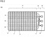
- FIG. 2 is a plan view for explaining a woven fabric 200 as a modification of the woven fabric 100.
- FIG. 2 is a view corresponding to FIG. 1A . This is different from FIG. 1A in a connection relationship with the first fiber 11 (an optical fiber) in the second region 52. Items not described are the same as those in the first exemplary embodiment.
- a connection between the optical fibers as the first fibers 11 and the light sources 20 is different from that in the first exemplary embodiment.
- the combination of an arrangement order of the first fibers 11 and the light sources 20 to be connected is different from that in the woven fabric 100.
- the first fibers 11 are alternately connected to the three types of light sources 20, respectively, in the arrangement order.
- FIGS. 3A to 3C are plan views for explaining a woven fabric 300 as a modification of the woven fabric 100.
- FIG. 3A is a plan view of the woven fabric 300 in an enlarged scale.
- FIG. 3B is a cross-sectional view of the woven fabric 300.
- FIG. 3C is a cross-sectional view of the woven fabric 300 in an enlarged scale.
- the first region 51 of the woven fabric 300 according to the third exemplary embodiment is different from that in the above exemplary embodiments. Others are the same as in the first and second exemplary embodiments, and therefore, are omitted.
- the first fiber 11 is a weft, and is an optical fiber.
- Second fibers 12a and 12b are warps, and fibers other than an optical fiber.
- the first fiber 11 intersects with the second fibers 12a and 12b.
- the second fiber 12a passes through a front portion of the first fiber 11 at a first intersection 31, and then passes through a rear portion of the first fiber 11 at a following second intersection 32.
- the second fiber 12b passes through each of a rear portion and a front portion of the first fiber 11 at the intersections.
- the second fiber 12a is contrary to the second fiber 12b, in passing through each of the front portion and the rear portion as described above at each intersection.
- the optical fiber of the first fiber 11 is fixed by opposite forces applied by the second fibers 12a and 12b from the upper and lower sides in a vertical direction.
- the position of the optical fiber may be fixed within the woven fabric 300.
- FIGS. 4A to 4C are plan views for explaining a woven fabric 400 as a modification of the woven fabric 100.
- FIG. 4A is a plan view of the woven fabric 400 according to the fourth exemplary embodiment.
- the woven fabric 400 includes the first fiber 11 and the second fibers 12a and 12b. Items not described are the same as those in the first to third exemplary embodiments. This exemplary embodiment is different from the above exemplary embodiments in the first region 51.
- the first fiber 11 is an optical fiber.
- the second fibers 12a and 12b are fibers other than an optical fiber.
- the first fiber 11 and the second fibers 12a and 12b may have a warp-weft relationship.
- the first fiber 11 intersects with the second fibers 12a and 12b.
- Each of the second fibers 12a and 12b passes through each of a rear portion and a front portion of the first fiber 11, at the first intersection 31. Thereafter, between the first intersection 31 and the following second intersection 32, left and right positions of both are switched. Then, each of the second fibers 12a and 12b passes through each of a rear portion and a front portion at the second intersection 32.
- FIG. 4B is a cross-sectional view of the woven fabric 400 in a direction parallel to the first fiber 11.
- FIG. 4C is a cross-sectional view of the woven fabric 400 in an enlarged scale.
- the weaving method in FIGS. 4A to 4C is a leno weave.
- FIG. 5 is a plan view of a woven fabric 500 according to a fifth exemplary embodiment.
- FIG. 5 is a plan view of the woven fabric 500 as a modification of the woven fabric 100 in FIG. 1A . Items not described are the same as those in the above exemplary embodiments.
- the second fiber 12 also uses an optical fiber. Items not described are the same as those in the above exemplary embodiments. Although not illustrated, at the lower side as well, there are the second region 52 and the third region 53. Likewise, although not illustrated, in the left-right directions as well, there are the fourth region 54, the fifth region 55, and the sixth region 56.
- the woven fabric 500 it is possible to emit light in the vertical-horizontal directions. It is possible to express optical images in various colors.
- FIG. 6 is a plan view of a woven fabric 600 according to a sixth exemplary embodiment.
- FIG. 6 is a schematic plan view of the woven fabric 600.
- FIG. 6 fibers visible from above are described in units of cells (square unit mass).
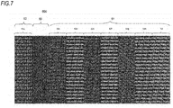
- FIG. 7 is a plan view of the woven fabric 600.
- FIG. 7 stereoscopically represents fibers visible from above. Items not described are the same as those in the above exemplary embodiments.
- the first region 51, the second region 52, and a ninth region 59 are included.
- the third region 53 is not illustrated, but it is desirable to provide the third region 53.
- the first region 51 is a region where an optical fiber emits light to the front surface.
- the second region 52 includes a bag region 52a. This is a region where the first fiber 11 is not woven with another fiber but is present alone. It is desirable that the first fiber 11 is not fixed by another fiber. This region is a region through which the optical fiber is connected to the light source 20 such as an LED in the third region 53 (not illustrated, FIGS. 1A to 1C ) connected to this region.
- the ninth region 59 is a region where the optical fiber is fixed in a state of being almost invisible from the front surface. The position of the optical fiber is kept within the woven fabric 600.
- the bag region 52a of the second region 52 there are the bag region 52a of the second region 52, the ninth region 59, the first region 51, a red emitting region 52c, a yellow emitting region 52d, a blue emitting region 52e, a red/yellow emitting region 52f, a red/blue emitting region 52g, a yellow/blue emitting region 52h, and a three-color emitting region 52i.
- the third region 53 in the first exemplary embodiment (a region where the light source 20 is connected to a fiber) is omitted. It is not necessary to provide all regions. At least one region of the bag region 52a of the second region 52, the ninth region 59, and the first region 51 suffices.
- the bag region 52a corresponds to the second region 52 in the first exemplary embodiment, where the fibers of the optical fibers are separated from other fibers. In this region, the light source 20 is connected to the optical fiber.
- the red emitting region 52c to the three-color emitting region 52i are regions where light is emitted. These regions emit light in red, yellow, blue, red/yellow, red/blue, yellow/blue, and three colors, respectively.
- the ninth region 59 is a fixing region where the optical fiber is fixed in a state of being almost invisible from the front surface.
- the ninth region 59 (the fixing region) may be provided in woven fabrics according to other exemplary embodiments.
- FIG. 8A is a side perspective view of the bag region 52a.
- FIG. 8B is a schematic side view of the bag region 52a.
- the second fiber 12a as a warp and a third fiber 13a as a weft form a first layer 61
- a blue fiber 10c is arranged between the first and second layers
- a yellow fiber 10b is arranged between the second and third layers
- a red fiber 10a is arranged between the third and fourth layers.
- the red fiber 10a, the yellow fiber 10b, and the blue fiber 10c are optical fibers that emit lights of respective colors.
- Other fibers are fibers other than optical fibers.
- the light only has to have three colors of red, green, and blue. Through the synthesis of three colors, various lights may be emitted.
- each of the red fiber 10a, the yellow fiber 10b, and the blue fiber 10c is not woven with another fiber, and thus is easily connected to the light source 20.
- Three fibers are classified into respective separate layers.
- FIG. 9A is a side perspective view of the three-color emitting region 52i.
- FIG. 9B is a schematic side view of the three-color emitting region 52i. On the left side of the drawing, the front surface is present.
- FIG. 9C is a schematic plan view of the three-color emitting region 52i.
- the second layer 62 as a lower layer constituted by the third fiber 13d and the second fiber 12a.
- the first layer 61 constituted by the second fiber 12a.
- the first layer 61 and the second layer 62 are coupled with each other by the third fiber 13a, the third fiber 13b, and the third fiber 13c.
- the red fiber 10a On the top of the first layer 61, the red fiber 10a, the yellow fiber 10b, and the blue fiber 10c are located. Each is coupled with the first layer 61 by the second fiber 12a.
- the red fiber 10a, the yellow fiber 10b, and the blue fiber 10c are located on the front surface, and fixed by only the second fiber 12a. Thus, it is possible to emit much light.
- the first layer 61 and the second layer 62 are coupled with each other by the third fibers 13a to 13c, thereby having a strength.
- the second layer 62 forms a solid foundation by the second fiber 12a and the third fiber 13d.
- red fiber 10a, the yellow fiber 10b, and the blue fiber 10c As can be seen from FIG. 9C , one second fiber 12a is located on the front portion, and 12 or 13 red fibers 10a, 12 or 13 yellow fibers 10b, and 12 or 13 blue fibers 10c are located on the front portion. This cycle is repeated. A large part of the red fiber 10a, the yellow fiber 10b, and the blue fiber 10c is located on the front surface side of the second fiber 12a to emit light.
- the one second fiber 12a holds each of the red fiber 10a, the yellow fiber 10b, and the blue fiber 10c.
- the number of fibers is 12 or 13.
- the number is shortened, a light emission ratio is reduced, and bending of fibers, that is, the red fiber 10a, the yellow fiber 10b, and the blue fiber 10c increases.
- a light guiding property deteriorates, and the light emission efficiency becomes not good.
- the number on the front portion increases, fixing of the red fiber 10a, the yellow fiber 10b, and the blue fiber 10c to a woven fabric becomes unstable. As a result, an exposed portion of an optical fiber becomes long, which becomes susceptible to a damage from the outside.
- One place where the second fiber 12a is located on the upper side is gradually shifted from each of the red fiber 10a, the yellow fiber 10b, and the blue fiber 10c, thereby improving the design property.
- an optical fiber emitting light is located on the front surface of the first layer 61 so as to be largely exposed on the front surface, and its front surface is covered with the second fiber 12a. Meanwhile, an optical fiber that does not need to emit light is located on the front surface of the second layer 62 and on the back surface of the first layer 61.
- FIG. 10A is a side view of the yellow/blue emitting region 52h.
- FIG. 10B is a schematic side view of the yellow/blue emitting region 52h. On the left side of the drawing, the front surface is present.
- the second layer 62 as a back layer constituted by the third fiber 13d and the second fiber 12a.
- the first layer 61 constituted by the second fiber 12a.
- the first layer 61 and the second layer 62 are coupled with each other by the third fiber 13a, the third fiber 13b, and the third fiber 13c.
- the yellow fiber 10b and the blue fiber 10c are located on the top of the first layer 61. Each is coupled with the first layer 61 by the second fiber 12a.
- the red fiber 10a is located between the first layer 61 and the second layer 62.
- the yellow fiber 10b and the blue fiber 10c are located on the front surface, and fixed by only the second fiber 12a.
- the red fiber 10a is almost invisible from the front surface, and is reliably protected while its bending or compression is reduced between the first layer 61 and the second layer 62, and its light guiding property is maintained.
- the first layer 61 and the second layer 62 are coupled with each other by the third fibers 13a to 13c, thereby having a strength.
- the second layer 62 forms a solid foundation by the second fiber 12a and the third fiber 13d.
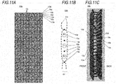
- FIG. 11A is a plan view of the ninth region 59 (the fixing region) .
- FIG. 11B is a schematic side view of the ninth region 59 (the fixing region).
- FIG. 11C is a perspective view of a side surface of the ninth region 59.
- the red fiber 10a, the yellow fiber 10b, and the blue fiber 10c are arranged between the four third fibers 13a to 13d. There is the second fiber 12a as a warp.
- the red fiber 10a, the yellow fiber 10b, and the blue fiber 10c have the same cycles at which one is exposed on the front portion of the second fiber 12a and three are located on the rear portion.
- the number is smaller than three, bending of the red fiber 10a, the yellow fiber 10b, and the blue fiber 10c increases, and thus the light emission efficiency deteriorates.
- the number is larger than three, fixability of the red fiber 10a, the yellow fiber 10b, and the blue fiber 10c becomes bad. It is desirable that the number ranges from three to five.
- the second region 52 ( FIG. 8B ), the ninth region 59b ( FIG. 11B ), and the first region 51 ( FIG. 9B , and FIG. 10B ) by arranging the red fiber 10a, the yellow fiber 10b, and the blue fiber 10c as optical fibers between the four third fibers 13a to 13d, and changing each position in the thickness direction. It is desirable that one fiber among the third fibers 13a to 13d has a larger diameter than other fibers. Accordingly, it is possible to secure the strength and flexibility of the woven fabric 600.
- the bag region 52a By configuring the light emitting region in two layers, the bag region 52a in four layers, and the fixing region in one layer, it is possible to sufficiently emit light while firmly holding the red fiber 10a, the yellow fiber 10b, and the blue fiber 10c. Then, a woven fabric with an overall strength is obtained.
- the woven fabric 600 can emit light in various colors, by three colors.
- the optical fiber In the ninth region 59 (the fixing region), the optical fiber can be fixed while its bending or compression is reduced, and its light guiding property is maintained.
- FIGS. 12A and 12B are plan views for explaining a woven fabric 700 as a modification of the woven fabric 100. Items not described are the same as those in the above exemplary embodiments.
- a tenth region 60 is located within the first region 51.
- the tenth region 60 is a region below.
- the first fiber 11 which is an optical fiber is positioned between the fourth fiber 14 and the second fiber 12 of the surface layer and the fourth fiber 14 of the back layer and the second fiber 12 in a state of being woven in a bag shape. And, the first fibers 11 are not woven by other fibers but exist alone. It is desirable that the first fiber 11 is not fixed. It is preferable that another fiber, the fourth fiber 14, and the like exist for protection in the surface layer and the upper layer of the first fiber 11.
- FIG. 12B is a plan view in which the woven fabric 700 of FIG. 12A is arranged on a surface having an obstacle 65 for attaching and connecting various kinds of parts and the like.
- the fourth fiber 14 and the second fiber 12 of the woven fabric 700 of the surface layer which is the fiber other than the first fiber 11 are cut off. In other words, it is to remove the woven fabric 60 a of the surface layer other than the first fibers 11 in the tenth region. Since the first fiber 11 and the fourth fiber 14 and the second fiber 12 of the woven fabric 700 of the surface layer and the back layer are not woven, they can be easily removed.
- the first fiber 11, which is an optical fiber since the first fiber 11, which is an optical fiber, is not woven by other fibers, it moves up and down, and obstacles 65 can be avoided. Without the tenth region 60, the first fiber 11, which is an optical fiber, is cut or pressed, so that light is not easily transmitted.
- a part of the fourth fiber 14 and the second fiber 12 which are fibers other than the first fiber 11 in the tenth region 60 may be left.
- the tenth region 60 may be located at an arbitrary place of the first region 51 or may be located in the vicinity or the outer peripheral portion of the first region 51, and a plurality of tenth regions 60 may be present.
- the outer peripheral portion is a region including a part of the outer peripheral side of the first region 51. In this case, at least one side of the outer periphery of the tenth region 60 is not surrounded by the first region 51. It is desirable that the tenth region 60 is designed to have a similar shape corresponding to the shape of the obstacle 65.
- FIG. 13 is a plan view of the woven fabric 700 in which a reinforcing portion 66 is further provided in FIG. 12B .
- the first fiber 11 is bent at a corresponding position due to the obstacle 65.
- the position is changed with the lapse of time. Therefore, it is desirable to provide the reinforcing portion 66 around the obstacle 65, or on the outer periphery inside the tenth region 60.
- the reinforcing portion 66 is, for example, a tape, an adhesive, or a fixture. Otherwise, as the reinforcing portion 66, another fiber may be additionally provided in a portion of the reinforcing portion 66. That is, in the region of the reinforcing portion 66, the fiber density may be made higher than that in another region.
- the exemplary embodiments may be combined with each other.
- the present disclosure is widely used as a woven fabric. This is used as, for example, a cloth of a door and a ceiling within an automobile, and a cloth of a wall, a ceiling, a chair of, for example, a tram or an airplane. Further, this is also used as a cloth for a wall of a structure, a house, a facility, and a building.
Landscapes
- Engineering & Computer Science (AREA)
- Textile Engineering (AREA)
- Physics & Mathematics (AREA)
- General Physics & Mathematics (AREA)
- Optics & Photonics (AREA)
- Woven Fabrics (AREA)
Abstract
Description
- The present disclosure relates to a woven fabric, and particularly to a woven fabric in which an optical fiber is put in a part of the woven fabric.
- A woven fabric in which an optical fiber is embedded in a part of the woven fabric has been taken into consideration in the related art. For example,
Patent Document 1 discloses a woven fabric in which an optical fiber is embedded in a part of the woven fabric. The optical fiber is connected to a light source, and light is emitted from the optical fiber. As a result, the woven fabric becomes a vivid woven fabric. - See, for example, Japanese Patent Laid-Open Publication No.
2010-267573 - In the woven fabric of
Patent Document 1, a method of connecting the optical fiber to the light source is not disclosed. It is unclear how to extract the optical fiber from the woven fabric, and connect the optical fiber to the light source. - The present disclosure has been made in view of these problems, and an object thereof is to provide an optical fiber woven fabric and a manufacturing method thereof, in which optical fibers may be easily extracted from the optical fiber woven fabric, and various types of light sources in various colors are freely combined according to a designated type or a coloration in a designated region, so that various types of complicated light emissions in various colors may be expressed.
- In order to solve the above problems, there is provided a woven fabric including: a first region where a first fiber as an optical fiber is woven with a second fiber as a non-optical fiber; a second region adjacent to the first region, in which the first fiber is not woven; and a third region adjacent to the second region, in which the first fiber is connected to a light source.
- According to the present disclosure, the position of the optical fiber may be fixed within the woven fabric.
-
-
FIG. 1A is a plan view of awoven fabric 100 according to a first exemplary embodiment,FIG. 1B is a cross-sectional view in a direction parallel to afirst fiber 11 of thewoven fabric 100, andFIG. 1C is a cross-sectional view of thewoven fabric 100 in an enlarged scale; -
FIG. 2 is a plan view of awoven fabric 200 according to a second exemplary embodiment; -
FIG. 3A is a plan view of awoven fabric 300 according to a third exemplary embodiment,FIG. 3B is a cross-sectional view in a direction parallel to afirst fiber 11 of thewoven fabric 300, andFIG. 3C is a cross-sectional view of thewoven fabric 300 in an enlarged scale; -
FIG. 4A is a plan view of awoven fabric 400 according to a fourth exemplary embodiment,FIG. 4B is a cross-sectional view in a direction parallel to afirst fiber 11 of thewoven fabric 400, andFIG. 4C is a cross-sectional view of thewoven fabric 400 in an enlarged scale; -
FIG. 5 is a plan view of awoven fabric 500 according to a fifth exemplary embodiment; -
FIG. 6 is a plan view of awoven fabric 600 according to a sixth exemplary embodiment; -
FIG. 7 is a plan view of thewoven fabric 600 according to the sixth exemplary embodiment; -
FIG. 8A is a side perspective view of abag region 52a in the sixth exemplary embodiment, andFIG. 8B is a schematic side view of thebag region 52a in the sixth exemplary embodiment; -
FIG. 9A is a side perspective view of a three-color emitting region 52i in the sixth exemplary embodiment,FIG. 9B is a schematic side view of the three-color emitting region 52i in the sixth exemplary embodiment, andFIG. 9C is a schematic plan view of the three-color emitting region 52i of thewoven fabric 600 in the sixth exemplary embodiment; -
FIG. 10A is a side perspective view of a yellow/blue emitting region 52h in the sixth exemplary embodiment; andFIG. 10B is a schematic side view of the yellow/blue emitting region 52h in the sixth exemplary embodiment; -
FIG. 11A is a plan view of aninth region 59b in the sixth exemplary embodiment,FIG. 11B is a schematic side view of theninth region 59b in the sixth exemplary embodiment, andFIG. 11C is a side perspective view of theninth region 59b in the sixth exemplary embodiment; -
FIGS. 12A and 12B are plan views of awoven fabric 700 in a seventh exemplary embodiment; and -
FIG. 13 is a plan view of thewoven fabric 700 in the seventh exemplary embodiment. - The present disclosure will be described by the following exemplary embodiments. The following exemplary embodiments are exemplary only and do not limit the present disclosure.
-
FIG. 1A is a plan view of awoven fabric 100 according to a first exemplary embodiment.FIG. 1B is a cross-sectional view of a portion of thewoven fabric 100 according to the first exemplary embodiment in which afirst fiber 11 is present on a front portion.FIG. 1C is a cross-sectional view of a portion of thewoven fabric 100 according to the first exemplary embodiment in which afourth fiber 14 is present on a rear portion. - The
woven fabric 100 has afirst region 51 to asixth region 56. - In the
first region 51, thefirst fiber 11, thefourth fiber 14, and asecond fiber 12 are woven as wefts and warps. - The
second region 52 is a region where thefirst fiber 11 is present alone. It is desirable that thefirst fiber 11 is not fixed. The portion of thesecond region 52 may be folded back so that thewoven fabric 100 may be mounted in, for example, an automobile. It is desirable that another fiber, such as thefourth fiber 14, is present for protection in the upper layer of thefirst fiber 11. - The
third region 53 is a region where thefirst fiber 11 is connected to alight source 20. Thefirst fiber 11 has a margin (degree of freedom) in the portion of thesecond region 52. - The
fourth region 54, thefifth region 55, and thesixth region 56 are partitioned regions for thelight sources 20, respectively. - A
seventh region 57 is a front surface layer of the wovenfabric 100. - An
eighth region 58 is a back surface layer or an internal layer of the wovenfabric 100. - Here, the
first fiber 11 is an optical fiber. It is desirable that the optical fiber is made of a resin from the viewpoint of a weaving property. Specifically, for example, (1) an optical fiber in which a core and a clad which do not allow total reflection but are correlated with a refractive index are combined, or (2) an optical fiber in which a core material is blended with a light scattering material may be used. - That is, the above (1) is a side emission-type optical fiber using a phenomenon in which light guided inside the core is not totally reflected between the core and the clad, and leaks. Meanwhile, the above (2) is a side emission-type optical fiber that has a structure in which light is not totally reflected at an interface between a core and a clad due to blending with the scattering material, and scattered light leaks from the side surface of the optical fiber.
- In such an optical fiber, it is possible to control the side surface emission luminance by adjusting the concentration of the light scattering material blended with the core material. Further, a side emission-type optical fiber having a configuration other than these may be employed. As these side emission-type optical fibers, only one type may be used, or two or more types may be used in combination.
- The diameter of the optical fiber is not particularly limited, but, from the viewpoint of suitably obtaining a weaving property, for example, the diameter may be 0.01 mm or more and 2.0 mm or less, preferably may be 0.05 mm or more and 1.5 mm or less, and more preferably 0.1 mm or more and 1.0 mm or less.
- It is not necessary that all the
first fibers 11 are optical fibers. The ratio is not limited, but is generally 10% or more, preferably 10% or more and 90% or less, more preferably 20% or more and 80% or less, and most preferably 30% or more and 70% or less. - A part of the
first fibers 11 may be the following non-light guiding yarns. Optical fibers in the following exemplary embodiments are also the same as those described above. - The
second fiber 12 and thefourth fiber 14 are non-conductive fibers, and are non-light guiding yarns, which are yarns not having a light guiding property unlike the optical fiber. Materials constituting thesecond fiber 12 and thefourth fiber 14 are not limited, and may be natural fibers or synthetic fibers. In the case of a synthetic fiber, as the constituent resins, a polyamide-based resin such as nylon 6 andnylon 66, a polyester-based resin such as polyethyleneterephthalate, polybutyleneterephthalate, and polytrimethyleneterephthalate, a polyolefin-based resin such as polypropylene, and a polyacryl-based resin may be exemplified. As these, only one type may be used, or two or more types may be used in combination. - The fineness of the
second fiber 12 and thefourth fiber 14 is not particularly limited, but may be, for example, 10 dtex or more and 5,000 dtex or less, preferably 20 dtex or more and 4,000 dtex or less, and more preferably 30 dtex or more and 3,000 dtex or less. - Meanwhile, it is more desirable that the fineness (diameter) of the optical fiber of the
first fiber 11 is smaller than thefourth fiber 14. - Each of the
second fiber 12 and thefourth fiber 14 may not include a light transmission inhibiting component, or may include a light transmission inhibiting component. When each of thesecond fiber 12 and thefourth fiber 14 includes a light transmission inhibiting component, it is possible to improve a light shielding property against the optical fiber. - The light transmission inhibiting component only has to be a component capable of inhibiting light transmission, and may inhibit light transmission by, for example, reflection·dispersion, light absorption, or other actions. Specifically, a colorant (e.g., a pigment or a dye), a light absorbent, and an extender (e.g., various fillers) may be exemplified. As these, only one type may be used, or two or more types maybe used in combination. Among them, for example, as the pigment, an organic pigment such as azo-based, phthalocyanine-based, perinone-based, perylene-based, and anthraquinone-based pigments, and an inorganic pigment such as carbon black, ultramarine, red iron oxide, titanium oxide, and iron oxide may be exemplified. As these, only one type may be used, or two or more types may be used in combination. As the dye, a dye such as anthraquinone-based, perinone-based, perylene-based, azo-based, methine-based, and quinoline-based dyes may be exemplified. Among them, a dye in darker color is desirable, and a black-based dye is particularly desirable. As these, only one type may be used, or two or more types may be used in combination.
- In the following exemplary embodiments, fibers other than an optical fiber are the same as the above-described fibers other than the optical fiber.
- The
light source 20 is a light source such as an LED. Here, inFIG. 1A , three LEDs may be used. When the three LEDs have three primary colors of red, green, and blue, thefourth region 54, thefifth region 55, and thesixth region 56 have different colors, respectively, so that thewoven fabric 100 becomes colorful. - Each of the
light sources 20 is connected to a power supply and a controller (a semiconductor device), and individually controlled. -
FIG. 2 is a plan view for explaining awoven fabric 200 as a modification of the wovenfabric 100. -
FIG. 2 is a view corresponding toFIG. 1A . This is different fromFIG. 1A in a connection relationship with the first fiber 11 (an optical fiber) in thesecond region 52. Items not described are the same as those in the first exemplary embodiment. - In the
woven fabric 200, a connection between the optical fibers as thefirst fibers 11 and thelight sources 20 is different from that in the first exemplary embodiment. In thewoven fabric 200, the combination of an arrangement order of thefirst fibers 11 and thelight sources 20 to be connected is different from that in thewoven fabric 100. In this case, thefirst fibers 11 are alternately connected to the three types oflight sources 20, respectively, in the arrangement order. - As a result, it is possible to express fine colors as compared to the first exemplary embodiment.
-
FIGS. 3A to 3C are plan views for explaining awoven fabric 300 as a modification of the wovenfabric 100. -
FIG. 3A is a plan view of the wovenfabric 300 in an enlarged scale.FIG. 3B is a cross-sectional view of the wovenfabric 300.FIG. 3C is a cross-sectional view of the wovenfabric 300 in an enlarged scale. - The
first region 51 of the wovenfabric 300 according to the third exemplary embodiment is different from that in the above exemplary embodiments. Others are the same as in the first and second exemplary embodiments, and therefore, are omitted. - The
first fiber 11 is a weft, and is an optical fiber.Second fibers - The
first fiber 11 intersects with thesecond fibers second fiber 12a passes through a front portion of thefirst fiber 11 at afirst intersection 31, and then passes through a rear portion of thefirst fiber 11 at a followingsecond intersection 32. Contrary to thesecond fiber 12a, thesecond fiber 12b passes through each of a rear portion and a front portion of thefirst fiber 11 at the intersections. Thesecond fiber 12a is contrary to thesecond fiber 12b, in passing through each of the front portion and the rear portion as described above at each intersection. - The optical fiber of the
first fiber 11 is fixed by opposite forces applied by thesecond fibers fabric 300. -
FIGS. 4A to 4C are plan views for explaining awoven fabric 400 as a modification of the wovenfabric 100. -
FIG. 4A is a plan view of the wovenfabric 400 according to the fourth exemplary embodiment. Thewoven fabric 400 includes thefirst fiber 11 and thesecond fibers first region 51. - The
first fiber 11 is an optical fiber. Thesecond fibers first fiber 11 and thesecond fibers - The
first fiber 11 intersects with thesecond fibers second fibers first fiber 11, at thefirst intersection 31. Thereafter, between thefirst intersection 31 and the followingsecond intersection 32, left and right positions of both are switched. Then, each of thesecond fibers second intersection 32. -
FIG. 4B is a cross-sectional view of the wovenfabric 400 in a direction parallel to thefirst fiber 11.FIG. 4C is a cross-sectional view of the wovenfabric 400 in an enlarged scale. - To the optical fiber of the
first fiber 11, forces are obliquely applied by thesecond fibers FIGS. 3A to 3C , bending of the optical fiber is small. The optical fiber is not largely bent, and thus is good in a light guiding property, and uniformly emits light. - The weaving method in
FIGS. 4A to 4C is a leno weave. -
FIG. 5 is a plan view of awoven fabric 500 according to a fifth exemplary embodiment.FIG. 5 is a plan view of the wovenfabric 500 as a modification of the wovenfabric 100 inFIG. 1A . Items not described are the same as those in the above exemplary embodiments. - In
FIG. 5 , unlike inFIG. 1A , thesecond fiber 12 also uses an optical fiber. Items not described are the same as those in the above exemplary embodiments. Although not illustrated, at the lower side as well, there are thesecond region 52 and thethird region 53. Likewise, although not illustrated, in the left-right directions as well, there are thefourth region 54, thefifth region 55, and thesixth region 56. - In the
woven fabric 500, it is possible to emit light in the vertical-horizontal directions. It is possible to express optical images in various colors. -
FIG. 6 is a plan view of awoven fabric 600 according to a sixth exemplary embodiment.FIG. 6 is a schematic plan view of the wovenfabric 600. - In
FIG. 6 , fibers visible from above are described in units of cells (square unit mass). -
FIG. 7 is a plan view of the wovenfabric 600.FIG. 7 stereoscopically represents fibers visible from above. Items not described are the same as those in the above exemplary embodiments. - The
first region 51, thesecond region 52, and aninth region 59 are included. Thethird region 53 is not illustrated, but it is desirable to provide thethird region 53. - The
first region 51 is a region where an optical fiber emits light to the front surface. - The
second region 52 includes abag region 52a. This is a region where thefirst fiber 11 is not woven with another fiber but is present alone. It is desirable that thefirst fiber 11 is not fixed by another fiber. This region is a region through which the optical fiber is connected to thelight source 20 such as an LED in the third region 53 (not illustrated,FIGS. 1A to 1C ) connected to this region. - The
ninth region 59 is a region where the optical fiber is fixed in a state of being almost invisible from the front surface. The position of the optical fiber is kept within the wovenfabric 600. - In the
woven fabric 600, there are thebag region 52a of thesecond region 52, theninth region 59, thefirst region 51, a redemitting region 52c, a yellowemitting region 52d, a blueemitting region 52e, a red/yellow emitting region 52f, a red/blue emitting region 52g, a yellow/blueemitting region 52h, and a three-color emitting region 52i. Thethird region 53 in the first exemplary embodiment (a region where thelight source 20 is connected to a fiber) is omitted. It is not necessary to provide all regions. At least one region of thebag region 52a of thesecond region 52, theninth region 59, and thefirst region 51 suffices. - The
bag region 52a corresponds to thesecond region 52 in the first exemplary embodiment, where the fibers of the optical fibers are separated from other fibers. In this region, thelight source 20 is connected to the optical fiber. - The red
emitting region 52c to the three-color emitting region 52i are regions where light is emitted. These regions emit light in red, yellow, blue, red/yellow, red/blue, yellow/blue, and three colors, respectively. - The
ninth region 59 is a fixing region where the optical fiber is fixed in a state of being almost invisible from the front surface. The ninth region 59 (the fixing region) may be provided in woven fabrics according to other exemplary embodiments. -
FIG. 8A is a side perspective view of thebag region 52a.FIG. 8B is a schematic side view of thebag region 52a. - The
second fiber 12a as a warp and athird fiber 13a as a weft form afirst layer 61, thesecond fiber 12a as a warp and athird fiber 13b as a weft form asecond layer 62, thesecond fiber 12a as a warp and athird fiber 13c as a weft form athird layer 63, and thesecond fiber 12a as a warp and athird fiber 13d as a weft form afourth layer 64. Ablue fiber 10c is arranged between the first and second layers, ayellow fiber 10b is arranged between the second and third layers, and ared fiber 10a is arranged between the third and fourth layers. - The
red fiber 10a, theyellow fiber 10b, and theblue fiber 10c are optical fibers that emit lights of respective colors. Other fibers are fibers other than optical fibers. The light only has to have three colors of red, green, and blue. Through the synthesis of three colors, various lights may be emitted. - In the
bag region 52a, each of thered fiber 10a, theyellow fiber 10b, and theblue fiber 10c is not woven with another fiber, and thus is easily connected to thelight source 20. Three fibers are classified into respective separate layers. -
FIG. 9A is a side perspective view of the three-color emitting region 52i.FIG. 9B is a schematic side view of the three-color emitting region 52i. On the left side of the drawing, the front surface is present.FIG. 9C is a schematic plan view of the three-color emitting region 52i. - There is the
second layer 62 as a lower layer constituted by thethird fiber 13d and thesecond fiber 12a. On the top of thesecond layer 62, there is thefirst layer 61 constituted by thesecond fiber 12a. Meanwhile, thefirst layer 61 and thesecond layer 62 are coupled with each other by thethird fiber 13a, thethird fiber 13b, and thethird fiber 13c. - On the top of the
first layer 61, thered fiber 10a, theyellow fiber 10b, and theblue fiber 10c are located. Each is coupled with thefirst layer 61 by thesecond fiber 12a. - Through this structure, the
red fiber 10a, theyellow fiber 10b, and theblue fiber 10c are located on the front surface, and fixed by only thesecond fiber 12a. Thus, it is possible to emit much light. - The
first layer 61 and thesecond layer 62 are coupled with each other by thethird fibers 13a to 13c, thereby having a strength. Thesecond layer 62 forms a solid foundation by thesecond fiber 12a and thethird fiber 13d. - For the
red fiber 10a, theyellow fiber 10b, and theblue fiber 10c, as can be seen fromFIG. 9C , onesecond fiber 12a is located on the front portion, and 12 or 13red fibers yellow fibers blue fibers 10c are located on the front portion. This cycle is repeated. A large part of thered fiber 10a, theyellow fiber 10b, and theblue fiber 10c is located on the front surface side of thesecond fiber 12a to emit light. - The one
second fiber 12a holds each of thered fiber 10a, theyellow fiber 10b, and theblue fiber 10c. In the cycle of thered fiber 10a, theyellow fiber 10b, and theblue fiber 10c on the front portion, the number of fibers is 12 or 13. When the number is shortened, a light emission ratio is reduced, and bending of fibers, that is, thered fiber 10a, theyellow fiber 10b, and theblue fiber 10c increases. Thus, a light guiding property deteriorates, and the light emission efficiency becomes not good. When the number on the front portion increases, fixing of thered fiber 10a, theyellow fiber 10b, and theblue fiber 10c to a woven fabric becomes unstable. As a result, an exposed portion of an optical fiber becomes long, which becomes susceptible to a damage from the outside. - One place where the
second fiber 12a is located on the upper side is gradually shifted from each of thered fiber 10a, theyellow fiber 10b, and theblue fiber 10c, thereby improving the design property. - In the red
emitting region 52c, the yellowemitting region 52d, theblue emitting region 52e, the red/yellow emitting region 52f, the red/blue emitting region 52g, and the yellow/blueemitting region 52h, an optical fiber emitting light is located on the front surface of thefirst layer 61 so as to be largely exposed on the front surface, and its front surface is covered with thesecond fiber 12a. Meanwhile, an optical fiber that does not need to emit light is located on the front surface of thesecond layer 62 and on the back surface of thefirst layer 61. -
FIG. 10A is a side view of the yellow/blueemitting region 52h.FIG. 10B is a schematic side view of the yellow/blueemitting region 52h. On the left side of the drawing, the front surface is present. - There is the
second layer 62 as a back layer constituted by thethird fiber 13d and thesecond fiber 12a. On the top of thesecond layer 62, there is thefirst layer 61 constituted by thesecond fiber 12a. Meanwhile, thefirst layer 61 and thesecond layer 62 are coupled with each other by thethird fiber 13a, thethird fiber 13b, and thethird fiber 13c. - On the top of the
first layer 61, theyellow fiber 10b and theblue fiber 10c are located. Each is coupled with thefirst layer 61 by thesecond fiber 12a. Thered fiber 10a is located between thefirst layer 61 and thesecond layer 62. - Through this structure, the
yellow fiber 10b and theblue fiber 10c are located on the front surface, and fixed by only thesecond fiber 12a. Thus, it is possible to emit much light. Thered fiber 10a is almost invisible from the front surface, and is reliably protected while its bending or compression is reduced between thefirst layer 61 and thesecond layer 62, and its light guiding property is maintained. - The
first layer 61 and thesecond layer 62 are coupled with each other by thethird fibers 13a to 13c, thereby having a strength. Thesecond layer 62 forms a solid foundation by thesecond fiber 12a and thethird fiber 13d. -
FIG. 11A is a plan view of the ninth region 59 (the fixing region) .FIG. 11B is a schematic side view of the ninth region 59 (the fixing region).FIG. 11C is a perspective view of a side surface of theninth region 59. - The
red fiber 10a, theyellow fiber 10b, and theblue fiber 10c are arranged between the fourthird fibers 13a to 13d. There is thesecond fiber 12a as a warp. - In the ninth region 59 (the fixing region), the
red fiber 10a, theyellow fiber 10b, and theblue fiber 10c have the same cycles at which one is exposed on the front portion of thesecond fiber 12a and three are located on the rear portion. When the number is smaller than three, bending of thered fiber 10a, theyellow fiber 10b, and theblue fiber 10c increases, and thus the light emission efficiency deteriorates. When the number is larger than three, fixability of thered fiber 10a, theyellow fiber 10b, and theblue fiber 10c becomes bad. It is desirable that the number ranges from three to five. - It is possible to form the second region 52 (
FIG. 8B ), theninth region 59b (FIG. 11B ), and the first region 51 (FIG. 9B , andFIG. 10B ) by arranging thered fiber 10a, theyellow fiber 10b, and theblue fiber 10c as optical fibers between the fourthird fibers 13a to 13d, and changing each position in the thickness direction. It is desirable that one fiber among thethird fibers 13a to 13d has a larger diameter than other fibers. Accordingly, it is possible to secure the strength and flexibility of the wovenfabric 600. - By configuring the light emitting region in two layers, the
bag region 52a in four layers, and the fixing region in one layer, it is possible to sufficiently emit light while firmly holding thered fiber 10a, theyellow fiber 10b, and theblue fiber 10c. Then, a woven fabric with an overall strength is obtained. - The
woven fabric 600 can emit light in various colors, by three colors. In the ninth region 59 (the fixing region), the optical fiber can be fixed while its bending or compression is reduced, and its light guiding property is maintained. -
FIGS. 12A and 12B are plan views for explaining awoven fabric 700 as a modification of the wovenfabric 100. Items not described are the same as those in the above exemplary embodiments. - In
FIG. 12A , in thewoven fabric 700, atenth region 60 is located within thefirst region 51. Like thesecond region 52, thetenth region 60 is a region below. Thefirst fiber 11 which is an optical fiber is positioned between thefourth fiber 14 and thesecond fiber 12 of the surface layer and thefourth fiber 14 of the back layer and thesecond fiber 12 in a state of being woven in a bag shape. And, thefirst fibers 11 are not woven by other fibers but exist alone. It is desirable that thefirst fiber 11 is not fixed. It is preferable that another fiber, thefourth fiber 14, and the like exist for protection in the surface layer and the upper layer of thefirst fiber 11. -
FIG. 12B is a plan view in which the wovenfabric 700 ofFIG. 12A is arranged on a surface having anobstacle 65 for attaching and connecting various kinds of parts and the like. At this time, thefourth fiber 14 and thesecond fiber 12 of the wovenfabric 700 of the surface layer which is the fiber other than thefirst fiber 11 are cut off. In other words, it is to remove the woven fabric 60 a of the surface layer other than thefirst fibers 11 in the tenth region. Since thefirst fiber 11 and thefourth fiber 14 and thesecond fiber 12 of the wovenfabric 700 of the surface layer and the back layer are not woven, they can be easily removed. As a result, in thetenth region 60, since thefirst fiber 11, which is an optical fiber, is not woven by other fibers, it moves up and down, andobstacles 65 can be avoided. Without thetenth region 60, thefirst fiber 11, which is an optical fiber, is cut or pressed, so that light is not easily transmitted. - A part of the
fourth fiber 14 and thesecond fiber 12 which are fibers other than thefirst fiber 11 in thetenth region 60 may be left. - The
tenth region 60 may be located at an arbitrary place of thefirst region 51 or may be located in the vicinity or the outer peripheral portion of thefirst region 51, and a plurality oftenth regions 60 may be present. Here, the outer peripheral portion is a region including a part of the outer peripheral side of thefirst region 51. In this case, at least one side of the outer periphery of thetenth region 60 is not surrounded by thefirst region 51. It is desirable that thetenth region 60 is designed to have a similar shape corresponding to the shape of theobstacle 65. -
FIG. 13 is a plan view of the wovenfabric 700 in which a reinforcingportion 66 is further provided inFIG. 12B . InFIG. 12B , thefirst fiber 11 is bent at a corresponding position due to theobstacle 65. Thus, there is a possibility that around thetenth region 60, the position is changed with the lapse of time. Therefore, it is desirable to provide the reinforcingportion 66 around theobstacle 65, or on the outer periphery inside thetenth region 60. - The reinforcing
portion 66 is, for example, a tape, an adhesive, or a fixture. Otherwise, as the reinforcingportion 66, another fiber may be additionally provided in a portion of the reinforcingportion 66. That is, in the region of the reinforcingportion 66, the fiber density may be made higher than that in another region. - The exemplary embodiments may be combined with each other.
- The present disclosure is widely used as a woven fabric. This is used as, for example, a cloth of a door and a ceiling within an automobile, and a cloth of a wall, a ceiling, a chair of, for example, a tram or an airplane. Further, this is also used as a cloth for a wall of a structure, a house, a facility, and a building.
Claims (13)
- A woven fabric comprising:a first region where a first fiber as an optical fiber is woven with a second fiber as a non-optical fiber to emit light;a second region adjacent to the first region, in which the first fiber is not woven; anda third region adjacent to the second region, in which the first fiber is connected to a light source.
- The woven fabric according to claim 1, wherein a plurality of light sources are included, which are light sources emitting light in different colors.
- The woven fabric according to claim 1, wherein the second fiber is also an optical fiber.
- The woven fabric according to claim 2, wherein a plurality of first fibers are arranged and are connected to different light sources in an arrangement order.
- The woven fabric according to any one of claims 1, wherein in the first region, two second fibers intersect with the first fiber and then positions of both are switched in a leno weave.
- The woven fabric according to any one of claims 1, wherein a structure of the first region, the second region, and the third region has two layers,
a layer on a front portion is a layer including the first fiber and the second fiber, and
a layer on a rear portion is a layer not including the first fiber. - The woven fabric according to any one of claims 1, comprising:a first layer in which the second fiber is woven with a third fiber,a second layer in which the second fiber is woven with the third fiber, andthe first fiber located between the first layer and the second layer.
- The woven fabric according to any one of claims 1, comprising a fixing region where the first fiber is fixed.
- The woven fabric according to claim 8, wherein the fixing region is a region where a cycle is repeated in which the first fiber is located on rear portions of three second fibers and is located on a front portion of one second fiber.
- The woven fabric according to any one of claims 1, wherein in the first region, a cycle is repeated in which the first fiber is located on front portions of 12 or 13 second fibers, and is located on a rear portion of one second fiber.
- The woven fabric according to any one of claims 1, wherein the second region is a region where the first fiber is interposed between the first layer and the second layer.
- The woven fabric according to any one of claims 1 wherein a tenth region where the first fiber is not woven is located within the first region or on an outer periphery portion.
- The woven fabric according to any one of claims 1, the tenth region in which the first fibers are not woven is located in the first region or the outer peripheral part.
Applications Claiming Priority (2)
| Application Number | Priority Date | Filing Date | Title |
|---|---|---|---|
| JP2017243312 | 2017-12-19 | ||
| JP2018212743A JP7264424B2 (en) | 2017-12-19 | 2018-11-13 | fabric |
Publications (2)
| Publication Number | Publication Date |
|---|---|
| EP3502329A1 true EP3502329A1 (en) | 2019-06-26 |
| EP3502329B1 EP3502329B1 (en) | 2021-08-25 |
Family
ID=64744393
Family Applications (1)
| Application Number | Title | Priority Date | Filing Date |
|---|---|---|---|
| EP18212969.2A Active EP3502329B1 (en) | 2017-12-19 | 2018-12-17 | Woven fabric with optical fibres |
Country Status (3)
| Country | Link |
|---|---|
| US (1) | US11268218B2 (en) |
| EP (1) | EP3502329B1 (en) |
| CN (1) | CN109930280B (en) |
Families Citing this family (6)
| Publication number | Priority date | Publication date | Assignee | Title |
|---|---|---|---|---|
| US10810868B2 (en) * | 2018-07-13 | 2020-10-20 | American Boronite Corporation | Infrared textile transmitter |
| DE102020112574B3 (en) * | 2020-05-08 | 2021-05-27 | Audi Aktiengesellschaft | Lighting device, lighting system and motor vehicle with lighting system |
| CN113957591A (en) * | 2021-09-23 | 2022-01-21 | 佛山市南海区源志诚织造有限公司 | Method for manufacturing optical fiber fabric capable of changing color along with music rhythm |
| CN114687045B (en) * | 2022-03-30 | 2022-11-25 | 歌尔科技有限公司 | Luminous fabric and equipment |
| WO2025152096A1 (en) * | 2024-01-18 | 2025-07-24 | Interfocus Inc. | Luminous fabric and method to make |
| TWI875484B (en) * | 2024-02-20 | 2025-03-01 | 和碩聯合科技股份有限公司 | Optical fiber cloth and lighting device |
Citations (4)
| Publication number | Priority date | Publication date | Assignee | Title |
|---|---|---|---|---|
| EP1307687A1 (en) * | 2000-08-07 | 2003-05-07 | Luminex S.p.A. | Textile product with illuminated fibres, article made therefrom and production method of the same |
| JP2007169807A (en) * | 2005-12-20 | 2007-07-05 | Mitsubishi Rayon Co Ltd | Optical fiber fabric, optical fiber fabric with leads, and manufacturing method thereof |
| JP2010267573A (en) | 2009-05-18 | 2010-11-25 | Nissan Motor Co Ltd | Fiber optic lighting equipment |
| JP2016037688A (en) * | 2014-08-11 | 2016-03-22 | 株式会社Shindo | Optical fiber fabric |
Family Cites Families (18)
| Publication number | Priority date | Publication date | Assignee | Title |
|---|---|---|---|---|
| US4234907A (en) * | 1979-01-29 | 1980-11-18 | Maurice Daniel | Light emitting fabric |
| US4885663A (en) * | 1988-03-22 | 1989-12-05 | Lumitex, Inc. | Fiber optic light emitting panel and method of making same |
| US4907132A (en) * | 1988-03-22 | 1990-03-06 | Lumitex, Inc. | Light emitting panel assemblies and method of making same |
| GB9908259D0 (en) * | 1999-04-13 | 1999-06-02 | Wilkie Mark I | Fibre-optics |
| US6480649B2 (en) * | 1999-08-18 | 2002-11-12 | Jean Hway Lee | Light-emitting device for emitting starry light |
| CN1707004A (en) * | 2004-06-08 | 2005-12-14 | 冠德光电科技股份有限公司 | Active Luminous and Reflective Fabrics |
| US7466896B2 (en) * | 2005-10-26 | 2008-12-16 | The Hong Kong Polytechnic University | Photonic fabric display with controlled pattern, color, luminescence intensity, scattering intensity and light self-amplification |
| CN1948578B (en) * | 2006-10-17 | 2011-05-18 | 浙江理工大学 | Controllable luminous fabric |
| EP2521931A4 (en) * | 2010-01-04 | 2018-01-03 | John Stephan | Illuminatable apparatus and method of manufacturing same |
| CN101962849B (en) * | 2010-08-05 | 2012-06-13 | 浙江理工大学 | Processing method of light-emitting fabrics with dynamic variation patterns |
| CN103792617B (en) * | 2014-01-24 | 2016-05-25 | 苏州创佳电子材料有限公司 | Optical fibers plate and manufacture method thereof and application |
| JP6710568B2 (en) | 2016-04-18 | 2020-06-17 | トヨタ紡織株式会社 | Skin material for vehicle interior |
| JP6597468B2 (en) * | 2016-04-20 | 2019-10-30 | トヨタ紡織株式会社 | Precursor fabric, fabric and manufacturing method thereof |
| JP6771951B2 (en) | 2016-05-26 | 2020-10-21 | トヨタ紡織株式会社 | Manufacturing method of woven fabric, design woven fabric and manufacturing method of interior material |
| US10228515B2 (en) | 2016-05-27 | 2019-03-12 | Toyota Boshoku Kabushiki Kaisha | Woven fabric |
| US10132014B2 (en) | 2016-05-27 | 2018-11-20 | Toyota Boshoku Kabushiki Kaisha | Woven fabric |
| JP6853529B2 (en) | 2016-12-13 | 2021-03-31 | トヨタ紡織株式会社 | Skin material for vehicle interior |
| KR101837405B1 (en) * | 2017-05-02 | 2018-03-12 | 국방과학연구소 | Active cloaking apparatus using optical fiber fabric displayf |
-
2018
- 2018-12-14 CN CN201811538783.3A patent/CN109930280B/en active Active
- 2018-12-17 US US16/222,987 patent/US11268218B2/en active Active
- 2018-12-17 EP EP18212969.2A patent/EP3502329B1/en active Active
Patent Citations (4)
| Publication number | Priority date | Publication date | Assignee | Title |
|---|---|---|---|---|
| EP1307687A1 (en) * | 2000-08-07 | 2003-05-07 | Luminex S.p.A. | Textile product with illuminated fibres, article made therefrom and production method of the same |
| JP2007169807A (en) * | 2005-12-20 | 2007-07-05 | Mitsubishi Rayon Co Ltd | Optical fiber fabric, optical fiber fabric with leads, and manufacturing method thereof |
| JP2010267573A (en) | 2009-05-18 | 2010-11-25 | Nissan Motor Co Ltd | Fiber optic lighting equipment |
| JP2016037688A (en) * | 2014-08-11 | 2016-03-22 | 株式会社Shindo | Optical fiber fabric |
Also Published As
| Publication number | Publication date |
|---|---|
| CN109930280B (en) | 2022-04-29 |
| CN109930280A (en) | 2019-06-25 |
| US20190186059A1 (en) | 2019-06-20 |
| EP3502329B1 (en) | 2021-08-25 |
| US11268218B2 (en) | 2022-03-08 |
Similar Documents
| Publication | Publication Date | Title |
|---|---|---|
| EP3502329B1 (en) | Woven fabric with optical fibres | |
| US10480775B2 (en) | Light emitting decoration, method for laying light emitting decoration, laying object and method for forming light emitting design | |
| US10228515B2 (en) | Woven fabric | |
| SG178130A1 (en) | Arrangement for generating light effects | |
| HU227954B1 (en) | High-visibility textile surface | |
| JP2016037688A (en) | Optical fiber fabric | |
| US20230089386A1 (en) | Shoe Upper with Illuminating Logo and Shoes Having the Same | |
| US10132014B2 (en) | Woven fabric | |
| JP2011042922A (en) | Woven fabric | |
| KR20120071870A (en) | Twisted optical fibers and fabrics including the same | |
| CN101044015B (en) | One-way visual screen | |
| EP3502330B1 (en) | Woven fabric with optical fibres | |
| JP2010504440A (en) | Textile with visual color change | |
| JP7264424B2 (en) | fabric | |
| JP2018131112A (en) | Vehicular interior material | |
| US10975503B2 (en) | Skin material for vehicle interior | |
| CN211390462U (en) | Anti-tearing seven-color three-layer screen cloth | |
| JP2018012375A (en) | Skin material | |
| CN217777969U (en) | Fluorescent reflecting ribbon | |
| JP2020042953A (en) | Light emitting fabric, its manufacturing method and luminescent ornament | |
| CN116103817A (en) | Luminous fabric with good pattern display effect and fabric weaving method thereof | |
| JP6621311B2 (en) | Textile, light-emitting device provided with the fabric, and clothing and apparel including the light-emitting device | |
| JP2006104585A (en) | Woven fabric | |
| HK1108858B (en) | One-way viewable screen |
Legal Events
| Date | Code | Title | Description |
|---|---|---|---|
| STAA | Information on the status of an ep patent application or granted ep patent |
Free format text: STATUS: EXAMINATION IS IN PROGRESS |
|
| PUAI | Public reference made under article 153(3) epc to a published international application that has entered the european phase |
Free format text: ORIGINAL CODE: 0009012 |
|
| 17P | Request for examination filed |
Effective date: 20181217 |
|
| AK | Designated contracting states |
Kind code of ref document: A1 Designated state(s): AL AT BE BG CH CY CZ DE DK EE ES FI FR GB GR HR HU IE IS IT LI LT LU LV MC MK MT NL NO PL PT RO RS SE SI SK SM TR |
|
| AX | Request for extension of the european patent |
Extension state: BA ME |
|
| GRAP | Despatch of communication of intention to grant a patent |
Free format text: ORIGINAL CODE: EPIDOSNIGR1 |
|
| STAA | Information on the status of an ep patent application or granted ep patent |
Free format text: STATUS: GRANT OF PATENT IS INTENDED |
|
| INTG | Intention to grant announced |
Effective date: 20210414 |
|
| GRAS | Grant fee paid |
Free format text: ORIGINAL CODE: EPIDOSNIGR3 |
|
| GRAA | (expected) grant |
Free format text: ORIGINAL CODE: 0009210 |
|
| STAA | Information on the status of an ep patent application or granted ep patent |
Free format text: STATUS: THE PATENT HAS BEEN GRANTED |
|
| AK | Designated contracting states |
Kind code of ref document: B1 Designated state(s): AL AT BE BG CH CY CZ DE DK EE ES FI FR GB GR HR HU IE IS IT LI LT LU LV MC MK MT NL NO PL PT RO RS SE SI SK SM TR |
|
| REG | Reference to a national code |
Ref country code: CH Ref legal event code: EP |
|
| REG | Reference to a national code |
Ref country code: IE Ref legal event code: FG4D Ref country code: AT Ref legal event code: REF Ref document number: 1423896 Country of ref document: AT Kind code of ref document: T Effective date: 20210915 |
|
| REG | Reference to a national code |
Ref country code: DE Ref legal event code: R096 Ref document number: 602018022329 Country of ref document: DE |
|
| REG | Reference to a national code |
Ref country code: LT Ref legal event code: MG9D |
|
| REG | Reference to a national code |
Ref country code: NL Ref legal event code: MP Effective date: 20210825 |
|
| REG | Reference to a national code |
Ref country code: AT Ref legal event code: MK05 Ref document number: 1423896 Country of ref document: AT Kind code of ref document: T Effective date: 20210825 |
|
| PG25 | Lapsed in a contracting state [announced via postgrant information from national office to epo] |
Ref country code: FI Free format text: LAPSE BECAUSE OF FAILURE TO SUBMIT A TRANSLATION OF THE DESCRIPTION OR TO PAY THE FEE WITHIN THE PRESCRIBED TIME-LIMIT Effective date: 20210825 Ref country code: ES Free format text: LAPSE BECAUSE OF FAILURE TO SUBMIT A TRANSLATION OF THE DESCRIPTION OR TO PAY THE FEE WITHIN THE PRESCRIBED TIME-LIMIT Effective date: 20210825 Ref country code: HR Free format text: LAPSE BECAUSE OF FAILURE TO SUBMIT A TRANSLATION OF THE DESCRIPTION OR TO PAY THE FEE WITHIN THE PRESCRIBED TIME-LIMIT Effective date: 20210825 Ref country code: SE Free format text: LAPSE BECAUSE OF FAILURE TO SUBMIT A TRANSLATION OF THE DESCRIPTION OR TO PAY THE FEE WITHIN THE PRESCRIBED TIME-LIMIT Effective date: 20210825 Ref country code: RS Free format text: LAPSE BECAUSE OF FAILURE TO SUBMIT A TRANSLATION OF THE DESCRIPTION OR TO PAY THE FEE WITHIN THE PRESCRIBED TIME-LIMIT Effective date: 20210825 Ref country code: NO Free format text: LAPSE BECAUSE OF FAILURE TO SUBMIT A TRANSLATION OF THE DESCRIPTION OR TO PAY THE FEE WITHIN THE PRESCRIBED TIME-LIMIT Effective date: 20211125 Ref country code: PT Free format text: LAPSE BECAUSE OF FAILURE TO SUBMIT A TRANSLATION OF THE DESCRIPTION OR TO PAY THE FEE WITHIN THE PRESCRIBED TIME-LIMIT Effective date: 20211227 Ref country code: BG Free format text: LAPSE BECAUSE OF FAILURE TO SUBMIT A TRANSLATION OF THE DESCRIPTION OR TO PAY THE FEE WITHIN THE PRESCRIBED TIME-LIMIT Effective date: 20211125 Ref country code: AT Free format text: LAPSE BECAUSE OF FAILURE TO SUBMIT A TRANSLATION OF THE DESCRIPTION OR TO PAY THE FEE WITHIN THE PRESCRIBED TIME-LIMIT Effective date: 20210825 Ref country code: LT Free format text: LAPSE BECAUSE OF FAILURE TO SUBMIT A TRANSLATION OF THE DESCRIPTION OR TO PAY THE FEE WITHIN THE PRESCRIBED TIME-LIMIT Effective date: 20210825 |
|
| REG | Reference to a national code |
Ref country code: DE Ref legal event code: R081 Ref document number: 602018022329 Country of ref document: DE Owner name: DAIKI CO., LTD., SAKAI-SHI, JP Free format text: FORMER OWNERS: DAIKI CO., LTD., SAKAI-SHI, FUKUI-KEN, JP; TOYOTA BOSHOKU KABUSHIKI KAISHA, KARIYA-SHI, AICHI-KEN, JP |
|
| PG25 | Lapsed in a contracting state [announced via postgrant information from national office to epo] |
Ref country code: PL Free format text: LAPSE BECAUSE OF FAILURE TO SUBMIT A TRANSLATION OF THE DESCRIPTION OR TO PAY THE FEE WITHIN THE PRESCRIBED TIME-LIMIT Effective date: 20210825 Ref country code: LV Free format text: LAPSE BECAUSE OF FAILURE TO SUBMIT A TRANSLATION OF THE DESCRIPTION OR TO PAY THE FEE WITHIN THE PRESCRIBED TIME-LIMIT Effective date: 20210825 Ref country code: GR Free format text: LAPSE BECAUSE OF FAILURE TO SUBMIT A TRANSLATION OF THE DESCRIPTION OR TO PAY THE FEE WITHIN THE PRESCRIBED TIME-LIMIT Effective date: 20211126 |
|
| PG25 | Lapsed in a contracting state [announced via postgrant information from national office to epo] |
Ref country code: NL Free format text: LAPSE BECAUSE OF FAILURE TO SUBMIT A TRANSLATION OF THE DESCRIPTION OR TO PAY THE FEE WITHIN THE PRESCRIBED TIME-LIMIT Effective date: 20210825 |
|
| PG25 | Lapsed in a contracting state [announced via postgrant information from national office to epo] |
Ref country code: DK Free format text: LAPSE BECAUSE OF FAILURE TO SUBMIT A TRANSLATION OF THE DESCRIPTION OR TO PAY THE FEE WITHIN THE PRESCRIBED TIME-LIMIT Effective date: 20210825 |
|
| REG | Reference to a national code |
Ref country code: DE Ref legal event code: R097 Ref document number: 602018022329 Country of ref document: DE |
|
| PG25 | Lapsed in a contracting state [announced via postgrant information from national office to epo] |
Ref country code: SM Free format text: LAPSE BECAUSE OF FAILURE TO SUBMIT A TRANSLATION OF THE DESCRIPTION OR TO PAY THE FEE WITHIN THE PRESCRIBED TIME-LIMIT Effective date: 20210825 Ref country code: SK Free format text: LAPSE BECAUSE OF FAILURE TO SUBMIT A TRANSLATION OF THE DESCRIPTION OR TO PAY THE FEE WITHIN THE PRESCRIBED TIME-LIMIT Effective date: 20210825 Ref country code: RO Free format text: LAPSE BECAUSE OF FAILURE TO SUBMIT A TRANSLATION OF THE DESCRIPTION OR TO PAY THE FEE WITHIN THE PRESCRIBED TIME-LIMIT Effective date: 20210825 Ref country code: EE Free format text: LAPSE BECAUSE OF FAILURE TO SUBMIT A TRANSLATION OF THE DESCRIPTION OR TO PAY THE FEE WITHIN THE PRESCRIBED TIME-LIMIT Effective date: 20210825 Ref country code: CZ Free format text: LAPSE BECAUSE OF FAILURE TO SUBMIT A TRANSLATION OF THE DESCRIPTION OR TO PAY THE FEE WITHIN THE PRESCRIBED TIME-LIMIT Effective date: 20210825 Ref country code: AL Free format text: LAPSE BECAUSE OF FAILURE TO SUBMIT A TRANSLATION OF THE DESCRIPTION OR TO PAY THE FEE WITHIN THE PRESCRIBED TIME-LIMIT Effective date: 20210825 |
|
| PLBE | No opposition filed within time limit |
Free format text: ORIGINAL CODE: 0009261 |
|
| STAA | Information on the status of an ep patent application or granted ep patent |
Free format text: STATUS: NO OPPOSITION FILED WITHIN TIME LIMIT |
|
| PG25 | Lapsed in a contracting state [announced via postgrant information from national office to epo] |
Ref country code: MC Free format text: LAPSE BECAUSE OF FAILURE TO SUBMIT A TRANSLATION OF THE DESCRIPTION OR TO PAY THE FEE WITHIN THE PRESCRIBED TIME-LIMIT Effective date: 20210825 Ref country code: IT Free format text: LAPSE BECAUSE OF FAILURE TO SUBMIT A TRANSLATION OF THE DESCRIPTION OR TO PAY THE FEE WITHIN THE PRESCRIBED TIME-LIMIT Effective date: 20210825 |
|
| REG | Reference to a national code |
Ref country code: CH Ref legal event code: PL |
|
| 26N | No opposition filed |
Effective date: 20220527 |
|
| PG25 | Lapsed in a contracting state [announced via postgrant information from national office to epo] |
Ref country code: SI Free format text: LAPSE BECAUSE OF FAILURE TO SUBMIT A TRANSLATION OF THE DESCRIPTION OR TO PAY THE FEE WITHIN THE PRESCRIBED TIME-LIMIT Effective date: 20210825 |
|
| REG | Reference to a national code |
Ref country code: BE Ref legal event code: MM Effective date: 20211231 |
|
| PG25 | Lapsed in a contracting state [announced via postgrant information from national office to epo] |
Ref country code: LU Free format text: LAPSE BECAUSE OF NON-PAYMENT OF DUE FEES Effective date: 20211217 Ref country code: IE Free format text: LAPSE BECAUSE OF NON-PAYMENT OF DUE FEES Effective date: 20211217 |
|
| PG25 | Lapsed in a contracting state [announced via postgrant information from national office to epo] |
Ref country code: BE Free format text: LAPSE BECAUSE OF NON-PAYMENT OF DUE FEES Effective date: 20211231 |
|
| PG25 | Lapsed in a contracting state [announced via postgrant information from national office to epo] |
Ref country code: LI Free format text: LAPSE BECAUSE OF NON-PAYMENT OF DUE FEES Effective date: 20211231 Ref country code: CH Free format text: LAPSE BECAUSE OF NON-PAYMENT OF DUE FEES Effective date: 20211231 |
|
| PG25 | Lapsed in a contracting state [announced via postgrant information from national office to epo] |
Ref country code: CY Free format text: LAPSE BECAUSE OF FAILURE TO SUBMIT A TRANSLATION OF THE DESCRIPTION OR TO PAY THE FEE WITHIN THE PRESCRIBED TIME-LIMIT Effective date: 20210825 |
|
| PG25 | Lapsed in a contracting state [announced via postgrant information from national office to epo] |
Ref country code: HU Free format text: LAPSE BECAUSE OF FAILURE TO SUBMIT A TRANSLATION OF THE DESCRIPTION OR TO PAY THE FEE WITHIN THE PRESCRIBED TIME-LIMIT; INVALID AB INITIO Effective date: 20181217 |
|
| GBPC | Gb: european patent ceased through non-payment of renewal fee |
Effective date: 20221217 |
|
| PG25 | Lapsed in a contracting state [announced via postgrant information from national office to epo] |
Ref country code: GB Free format text: LAPSE BECAUSE OF NON-PAYMENT OF DUE FEES Effective date: 20221217 |
|
| PG25 | Lapsed in a contracting state [announced via postgrant information from national office to epo] |
Ref country code: MK Free format text: LAPSE BECAUSE OF FAILURE TO SUBMIT A TRANSLATION OF THE DESCRIPTION OR TO PAY THE FEE WITHIN THE PRESCRIBED TIME-LIMIT Effective date: 20210825 |
|
| PG25 | Lapsed in a contracting state [announced via postgrant information from national office to epo] |
Ref country code: TR Free format text: LAPSE BECAUSE OF FAILURE TO SUBMIT A TRANSLATION OF THE DESCRIPTION OR TO PAY THE FEE WITHIN THE PRESCRIBED TIME-LIMIT Effective date: 20210825 |
|
| PG25 | Lapsed in a contracting state [announced via postgrant information from national office to epo] |
Ref country code: MT Free format text: LAPSE BECAUSE OF FAILURE TO SUBMIT A TRANSLATION OF THE DESCRIPTION OR TO PAY THE FEE WITHIN THE PRESCRIBED TIME-LIMIT Effective date: 20210825 |
|
| PGFP | Annual fee paid to national office [announced via postgrant information from national office to epo] |
Ref country code: FR Payment date: 20251229 Year of fee payment: 8 |
|
| PGFP | Annual fee paid to national office [announced via postgrant information from national office to epo] |
Ref country code: DE Payment date: 20251230 Year of fee payment: 8 |