EP3501993B1 - Lumière extérieure d'aéronef et aéronef la comprenant - Google Patents
Lumière extérieure d'aéronef et aéronef la comprenant Download PDFInfo
- Publication number
- EP3501993B1 EP3501993B1 EP17210560.3A EP17210560A EP3501993B1 EP 3501993 B1 EP3501993 B1 EP 3501993B1 EP 17210560 A EP17210560 A EP 17210560A EP 3501993 B1 EP3501993 B1 EP 3501993B1
- Authority
- EP
- European Patent Office
- Prior art keywords
- light
- light source
- switchable illumination
- temperature
- exterior aircraft
- Prior art date
- Legal status (The legal status is an assumption and is not a legal conclusion. Google has not performed a legal analysis and makes no representation as to the accuracy of the status listed.)
- Active
Links
- 238000005286 illumination Methods 0.000 claims description 98
- 238000000034 method Methods 0.000 claims description 5
- 238000004891 communication Methods 0.000 description 7
- 230000009286 beneficial effect Effects 0.000 description 5
- 230000001276 controlling effect Effects 0.000 description 5
- 238000001514 detection method Methods 0.000 description 3
- 238000009434 installation Methods 0.000 description 3
- 238000010586 diagram Methods 0.000 description 2
- 230000000694 effects Effects 0.000 description 2
- 230000012447 hatching Effects 0.000 description 2
- 230000004048 modification Effects 0.000 description 2
- 238000012986 modification Methods 0.000 description 2
- 230000000737 periodic effect Effects 0.000 description 2
- 230000003213 activating effect Effects 0.000 description 1
- 230000006978 adaptation Effects 0.000 description 1
- 230000032683 aging Effects 0.000 description 1
- 230000033228 biological regulation Effects 0.000 description 1
- 238000009529 body temperature measurement Methods 0.000 description 1
- 230000007423 decrease Effects 0.000 description 1
- 230000004907 flux Effects 0.000 description 1
- 239000000463 material Substances 0.000 description 1
- 238000005259 measurement Methods 0.000 description 1
- 238000012544 monitoring process Methods 0.000 description 1
- 238000013021 overheating Methods 0.000 description 1
- 230000009467 reduction Effects 0.000 description 1
- 230000001105 regulatory effect Effects 0.000 description 1
- 239000004065 semiconductor Substances 0.000 description 1
- 230000011664 signaling Effects 0.000 description 1
- 239000013585 weight reducing agent Substances 0.000 description 1
Images


Classifications
-
- H—ELECTRICITY
- H05—ELECTRIC TECHNIQUES NOT OTHERWISE PROVIDED FOR
- H05B—ELECTRIC HEATING; ELECTRIC LIGHT SOURCES NOT OTHERWISE PROVIDED FOR; CIRCUIT ARRANGEMENTS FOR ELECTRIC LIGHT SOURCES, IN GENERAL
- H05B45/00—Circuit arrangements for operating light-emitting diodes [LED]
- H05B45/10—Controlling the intensity of the light
- H05B45/18—Controlling the intensity of the light using temperature feedback
-
- B—PERFORMING OPERATIONS; TRANSPORTING
- B64—AIRCRAFT; AVIATION; COSMONAUTICS
- B64D—EQUIPMENT FOR FITTING IN OR TO AIRCRAFT; FLIGHT SUITS; PARACHUTES; ARRANGEMENT OR MOUNTING OF POWER PLANTS OR PROPULSION TRANSMISSIONS IN AIRCRAFT
- B64D47/00—Equipment not otherwise provided for
- B64D47/02—Arrangements or adaptations of signal or lighting devices
- B64D47/06—Arrangements or adaptations of signal or lighting devices for indicating aircraft presence
-
- H—ELECTRICITY
- H05—ELECTRIC TECHNIQUES NOT OTHERWISE PROVIDED FOR
- H05B—ELECTRIC HEATING; ELECTRIC LIGHT SOURCES NOT OTHERWISE PROVIDED FOR; CIRCUIT ARRANGEMENTS FOR ELECTRIC LIGHT SOURCES, IN GENERAL
- H05B45/00—Circuit arrangements for operating light-emitting diodes [LED]
- H05B45/10—Controlling the intensity of the light
- H05B45/14—Controlling the intensity of the light using electrical feedback from LEDs or from LED modules
-
- H—ELECTRICITY
- H05—ELECTRIC TECHNIQUES NOT OTHERWISE PROVIDED FOR
- H05B—ELECTRIC HEATING; ELECTRIC LIGHT SOURCES NOT OTHERWISE PROVIDED FOR; CIRCUIT ARRANGEMENTS FOR ELECTRIC LIGHT SOURCES, IN GENERAL
- H05B45/00—Circuit arrangements for operating light-emitting diodes [LED]
- H05B45/30—Driver circuits
- H05B45/305—Frequency-control circuits
-
- H—ELECTRICITY
- H05—ELECTRIC TECHNIQUES NOT OTHERWISE PROVIDED FOR
- H05B—ELECTRIC HEATING; ELECTRIC LIGHT SOURCES NOT OTHERWISE PROVIDED FOR; CIRCUIT ARRANGEMENTS FOR ELECTRIC LIGHT SOURCES, IN GENERAL
- H05B45/00—Circuit arrangements for operating light-emitting diodes [LED]
- H05B45/30—Driver circuits
- H05B45/37—Converter circuits
-
- B—PERFORMING OPERATIONS; TRANSPORTING
- B64—AIRCRAFT; AVIATION; COSMONAUTICS
- B64D—EQUIPMENT FOR FITTING IN OR TO AIRCRAFT; FLIGHT SUITS; PARACHUTES; ARRANGEMENT OR MOUNTING OF POWER PLANTS OR PROPULSION TRANSMISSIONS IN AIRCRAFT
- B64D2203/00—Aircraft or airfield lights using LEDs
Definitions
- the present invention relates to aircraft lighting. It in particular relates to an exterior aircraft light and, more particularly, to an exterior aircraft light having multiple light sources. It further relates to a method of operating such an exterior aircraft light and to an aircraft comprising such an exterior aircraft light.
- Exterior lights Almost all aircraft are equipped with exterior lights.
- large passenger air planes are provided with a wide variety of exterior lights.
- the exterior lights are provided for a wide variety of different purposes, such as for allowing the passengers and/or air crew to view the outside, for passive visibility, for signaling purposes, etc.
- Examples of such exterior lights are navigation lights, also referred to as position lights, beacon lights, anti-collision lights, wing scan lights, take-off lights, landing lights, taxi lights, runway turn-off lights, etc.
- Each of said exterior lights may comprise a plurality of light sources.
- the temperature of said light sources increases.
- heat sinks are provided in thermal connection with the light sources for dissipating the heat generated by operating the light sources.
- the heat sinks would be designed so that the thermal loads / temperatures of all light sources of an exterior light are the same in order to allow operating all light sources simultaneously with good efficiency.
- the heat sinks are often not ideal in real life exterior lights, so that the thermal loads / temperatures of the light sources of an exterior light are not the same. As a result, not all light sources of the exterior light may be operated simultaneously with good efficiency.
- US 2007/040696 A1 discloses a system and method for monitoring the operational life and/or performance of one or more light-emitting diodes (LEDs) based on sensed parameters are disclosed.
- the remaining life of each LED may be predicted by counting the clock cycles during which the LED-based light is activated.
- LED current and/or temperature measurements may be used to control the clock signal and, thus, to compensate the predicted life value.
- operational characteristics of the LED-based light may be monitored based on LED current and/or voltage measurements. Such characteristics may include performance (e.g., intensity) and failure conditions (e.g., open or short circuits).
- EP 2 607 238 A1 discloses an anti-collision aircraft light.
- the anti-collision aircraft light comprises at least one LED and a control unit for operating the at least one LED in a pulsed manner.
- the control unit comprises an ambient temperature sensor for sensing the ambient temperature and an adjustable current control means for setting an LED operating current depending on the sensed ambient temperature.
- the control unit further includes a light intensity sensor for sensing the intensity of the light emitted from the at least one LED, a integrator connected to the light sensor for integrating the sensed light intensity, and a comparator for comparing the integrated light intensity to a threshold value.
- the operating current for the at least one LED is interrupted as soon as the integrated light intensity is equal to the threshold value.
- US 2016/227616 A1 discloses a light emitting diode (LED) driving device which includes a power supply module configured to supply driving power to a light source.
- the light source includes a plurality of LED elements, an information acquisition module configured to acquire operating data of the power supply module and characteristic data of the plurality of LED elements, and a control module configured to control an operation of the power supply module based on the operating data and the characteristic data.
- the information acquisition module and the control module are included in a programmable microcontroller unit (MCU).
- the MCU executes stored codes to provide control signals to the control module to operate the power supply module.
- a first aspect of the invention includes an exterior aircraft light according to independent claim 1.
- a second aspect of the invention includes a method of operating an exterior aircraft light according to independent claim 14.
- the "temperature of the at least one light source” may be the temperature of the at least one light source itself or the temperature of an area surrounding the respective light source or any other detectable temperature value that is a good indication of the temperature of the at least one light source itself.
- the temperature detector may be or may include a temperature sensitive element, i.e. a temperature sensor, configured for directly detecting / measuring the temperature of or close to the associated light source.
- the temperature detector may be or may include a temperature determination element, which is configured for determining the actual temperature indirectly, e.g. from the light emission generated by the respective light source, the current at the respective light source or similar parameters.
- Switching power flow to the at least one light source repeatedly on and off allows for operating the light sources at beneficial or even optimal thermal operation points and for preventing that a predetermined threshold (upper limit) of a desired temperature range for the at least one light source is exceeded.
- a predetermined threshold upper limit
- the temperature of the at least one light source may stay within desirable / acceptable limits.
- the at least one light source can repeatedly cool down.
- the control circuit in particular may be configured for controlling the electric switch to switch power flow to the at least one light source so that the temperature detected by the temperature detector does not deviate more than 10%, in particular not more than 5%, from a given reference temperature value.
- the reference temperature value may be predetermined or set by a global control circuit, e.g. for leveling among different switchable illumination circuits. Alternatively, the reference temperature value may be provided by the manufacturer of the respective light source(s) representing the preferred temperature for operating the respective light source.
- the light emissions of the light sources may be achieved efficiently at a low risk of damaging the light sources due to overheating.
- a similar or even uniform aging of the light sources may be achieved.
- true energy savings can be achieved by turning the power flow to the light sources off repeatedly.
- the temperature control of the at least one light source may be carried out within the switchable illumination circuit.
- the switchable illumination circuit is a stand-alone entity that provides for detection of the temperature at the at least one light source and for adaptation of the electric behavior in order to regulate the temperature.
- no communication outside of the switchable illumination circuit in particular no communication to a power supply, is required for keeping the temperature of the at least one light source in a desired range. In this way, wiring and/or other communication components to a power supply can be saved. This in turn may lead to a space and weight reduction of the exterior aircraft light.
- Repeatedly switching the power flow to the at least one light source on and off may result in repeatedly switching the at least one light source on and off.
- switching the power flow to the at least one light source on and off may instantly or quasi-instantly result in switching the at least one light source on and off.
- control circuit is configured for driving the electric switch to periodically switch power flow to the at least one light source on and off.
- the control circuit in particular may be configured for adjusting a duty cycle of the signal driving the electric switch based on the temperature signal provided by the at least one temperature detector. This results in a PWM modulation of the power flow to the at least one light source allowing for a very efficient control of the temperature and light emission of the at least one light source.
- control circuit is configured for driving the electric switch to switch power flow to the at least one light source on and off with a frequency of 100 Hz to 20 kHz, in particular with a frequency of 100 Hz to 1 kHz, more particularly with a frequency of 400 Hz to 500 Hz.
- the resulting switching of the at least one light source is not recognized by the human eye. As a result, the switching has no negative effect on the impression of illumination provided by the exterior aircraft light.
- each of the at least two switchable illumination circuits comprises a current bypass and the electric switch is configured for bypassing the electric current by the at least one light source via the current bypass in order to switch off power flow to the at least one light source.
- Bypassing the electric current by the at least one light source for deactivating the at least one light source allows switching a plurality of serially connected switchable illumination circuits independently of each other as the supply of electric current / power to the switchable illumination circuits is not interrupted when at least one of the switchable illumination circuits is switched off.
- Providing a series connection of switchable illumination circuits allows for an easy installation of a plurality of switchable illumination circuits at low costs. Also, when bypassing the electric current by the at least one light source, electric energy can be saved.
- the voltage drop otherwise caused by the at least one light source can be prevented.
- the bypass current having the same value as the electric current otherwise going through the at least one light source, electric power up to the product of said electric current and the voltage drop at the at least one light source can be saved.
- the current bypass may be a simple wire, leading to very high energy savings, or may have one or few circuit components, such as a simple diode and/or a small value resistor, or any other suitable circuit structure.
- the electric switch may be configured for interrupting the electric current through the switchable illumination circuit in order to switch off power flow to the at least one light source.
- the electric current through the switchable illumination circuit is not diverted through a current bypass, but stopped completely. In this way, even larger energy savings and/or larger reductions of thermal losses can be achieved.
- the temperature detector is or includes a temperature sensitive element, which is configured for directly detecting the temperature of the respective at least one light source. Temperature sensitive elements allow for a direct detection of the temperatures at the light sources.
- the temperature detector is or includes a temperature determination element, which is configured for determining the temperature of the respective light source indirectly from at least one other detected or measured parameter.
- Said parameters may include the flux generated by the respective light source or a current measured at the electric connectors of the light source. This allows for a good proxy detection of the temperatures at the light sources without using temperature sensitive elements.
- the at least one light source, the temperature detector, the electric switch and the control circuit of each of the at least two switchable illumination circuits in particular may be arranged within 6 cm or less from each other.
- Such functional units allow for compact exterior aircraft lights which need only small space for installation. Also, providing such functional units allows for providing the temperature control close to the at least one light source, keeping the wiring and communication efforts for the temperature control very low.
- the at least one light source is at least one LED.
- LEDs are efficient light sources having a high reliability and a long lifetime, which may be provided at low costs.
- the temperature control within the switchable illumination circuit is particularly useful for exterior aircraft lights having LEDs as light sources. Keeping the operating temperature within acceptable limits has a particularly beneficial effect on the efficiency and longevity of LEDs.
- the at least one light source is a plurality of light sources which are connected serially or in parallel to each other. Connecting a plurality of light source serially or in parallel to each other for forming a light source group allows for controlling the temperature of a plurality of light sources employing only a single temperature detector, a single electric switch and a single control circuit, respectively.
- providing a plurality of light sources in series is a low complexity implementation for ensuring that these light sources receive the same current, thus achieving a nominally identical behavior of these light sources with low complexity.
- the exterior aircraft light further comprises an electric power supply which is configured for supplying a constant electric current to each of the at least two switchable illumination circuits.
- the electric power supply in particular may be spatially separated from the at least two switchable illumination circuits.
- the electric power supply for example may be located in a distance of between 0.2 m and 10 m, in particular of between 0.2 m and 1 m, further in particular of between 0.2 m and 0.5 m, from the at least two switchable illumination circuits.
- the electric power supply may a current source.
- the electric power supply may be a regulated current source that provides for a fast regulation of the output current.
- the electric power supply may be a current source that regulates its output current to a desired current value within 0.001 seconds.
- the current source may be able to react very fast to the switching changes in the switchable illumination circuits, thus achieving a highly constant current through the switchable illumination circuits, in particular when individual ones of multiple switchable illumination circuits are subject to a repeated on/off switching of the power flow to the at least one light source, and realizing the energy savings made possible by switching the power flow to the light source(s) off.
- the electric power supply may be integrated into the exterior aircraft light, with the at least two switchable illumination circuits for providing a compact autonomous exterior aircraft light.
- the electric power supply may be located e.g. in the fuselage of the aircraft, while each of the at least two switchable illumination circuits comprising the at least one light source is located in a wing or at a gear of the aircraft.
- This provides an exterior aircraft light having less weight and reduced dimensions, which may be beneficial when the exterior aircraft light is mounted to a wing or to a gear of the aircraft
- the control circuit is independent from the electric power supply, i.e. the control circuit is spatially separated from the electric power supply and is configured to be operated independent from the electric power supply.
- an independently operated electric power supply may be able to react to the power demands caused by the control circuit(s) of the switchable illumination circuit(s) in order to provide a basically constant electric current under all operating conditions, in particular independent of the number of lights sources switched on and off.
- the independently operated electric power supply may react to the changing power demands of the one or more switchable illumination circuits, without receiving according communications or signals from the one or more switchable illumination circuits. Rather, the independently operated electric power supply may be configured to provide a certain kind of power, such as a certain operating current, irrespective of the momentary load.
- the control circuit is independent from other global control means provided within the aircraft. An independent control circuit, however, might be configured to receive at least one temperature reference value from a global control means in order to synchronize the temperatures of the light sources within the aircraft.
- the at least two switchable illumination circuits are a plurality of switchable illumination circuits, wherein the plurality of switchable illumination circuits are in particular 3, 4, 5, 6, 7, 8, 9, 10 or more switchable illumination circuits.
- Such a configuration allows for individually controlling the temperatures of various sets of light sources provided in an exterior aircraft light.
- variable current bypass components may be particularly useful in a taxi light, a landing light, a take-off light, or a runway turn-off light.
- above terms also include multi-purpose lights having one or more of the given functionalities.
- the term landing light includes a combined landing, takeoff, and taxi light.
- the exterior aircraft light has the above described structure including the at least two switchable illumination circuits for controlling the temperatures of the respective light sources.
- Exemplary embodiments of the invention further include an aircraft, such as an airplane or a helicopter, comprising at least one exterior aircraft light, as described in any of the embodiments above.
- an aircraft such as an airplane or a helicopter
- the exterior aircraft light as described in any of the embodiments above.
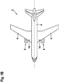
- Fig. 1A shows a side view of an aircraft 2 comprising exterior aircraft lights 12, 14 according to exemplary embodiments of the invention, and Fig. 1B shows a top view of said aircraft 2.
- the aircraft 2 is an airplane 2 comprising a fuselage 4 and two wings 6 extending from the fuselage 4.
- a jet engine 8 is mounted to each of the wings 6.
- the invention may be applied to aircraft 2 comprising propellers (not shown) instead of jet engines 8 and to aircraft 2 in which the engine(s) 8 or propeller(s) are mounted to the fuselage 4 instead of the wings 6.
- exemplary embodiments also may include exterior aircraft lights 13 mounted to a helicopter 3, as depicted in Fig. 2 .
- the aircraft / airplane 2 shown in Figs. 1A and 1B comprises a front running gear and at least one main running gear 11.
- a first exterior aircraft light 12 is mounted to the front running gear 10.
- Two second exterior aircraft lights 14 are mounted to or integrated with each of the wings 6.
- the second exterior aircraft lights 14 are integrated into respective wing root portions of the wings 6.
- the second aircraft lights 14 are not visible in Fig. 1A , as they are covered by the engine 8 and/or the fuselage 4.
- the first aircraft light 12 is not visible in Fig. 1B , as it is covered by the fuselage 4 of the aircraft 2.
- exterior aircraft lights may be mounted to at least one of the main running gear 11 and/or to the fuselage 4 of the aircraft 2.
- Each of the exterior aircraft lights 12, 14 is one of a landing light, a taxi light, a runway turn-off light, a take-off light, and a multipurpose exterior aircraft light 12, 14 combining the functionality of at least two of a landing light, a taxi light, a runway turn-off light and a take-off light.
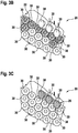
- the multi-purpose exterior aircraft light 20 comprises a plurality of light source units 30, each of the light source units comprising a light source and a reflector, with the reflector directing the light from the light source into a desired direction.
- the multi-purpose exterior aircraft light 20 of the exemplary embodiment of Fig. 3 comprises a plurality of groups 22, 24, 26, 28 of light source units 30.
- the light source units 30 of a first group 22 are configured to provide a landing light functionality;
- the light source units 30 of a second group 24 are configured to provide a taxi light functionality;
- the light source units 30 of a third group 26 are configured to provide a runway turn-off light (RTO light) functionality;
- the light source units 30 of a fourth group 28 are configured to provide a take-off light functionality.
- a multi-purpose exterior aircraft light 20 may comprise only two or three of said groups 22, 24, 26, 28, and the additional functionalities may be provided by additional exterior aircraft lights which are separate from the multi-purpose exterior aircraft light 20.
- Figs. 3A , 3B, and 3C selected ones of the groups 22, 24, 26, 28 are overlaid with hatching, in order to illustrate which ones of the light source units 30 belong to which groups 22, 24, 26, 28.
- the hatching is an aid in the Figs. for purely illustrative purposes.
- each of the exterior aircraft lights 12, 14 and the exterior aircraft light 30 comprises at least one light source, such as an LED.
- the temperature of the at least one light source increases.
- the operating temperature should stay within an acceptable temperature range.
- the temperature of the at least one light source should not exceed a predetermined maximum temperature.
- the temperature of the light sources may differ, depending e.g. on their mounting positions and their local environment. For example, when looking at a particular light source, other light sources located next to the particular light source may contribute to the thermal load of the particular light source. Also, it is possible that due to space constraints, the heat sink of a particular light source may be smaller than would be desirable.
- Fig. 4 shows an example of an exterior aircraft light 20 comprising one switchable illumination circuit 32.
- the switchable illumination circuit 32 is configured to allow operating the at least one light source 34 thereof with high efficiency, without exceeding a predetermined maximum temperature of the respective light source 34.
- the light source 34 depicted in Fig. 4 may represent a plurality of light sources connected in series or in parallel to each other.
- the switchable illumination circuit 32 is electrically connected to an electric power supply 40, which is configured for supplying an electric current, in particular a constant electric current, to the switchable illumination circuit 32.
- the electric power supply 40 may be spatially separated from the switchable illumination circuit 32.
- the electric power supply 40 for example may have a distance of between 0.2 m and 10 m, in particular of between 0.2 m and 1 m, further in particular of between 0.2 m and 0.5 m, from the switchable illumination circuit 32.
- the electric power supply 40 may be integrated into the exterior aircraft light 12, 14 together with the switchable illumination circuit 32.
- the electric power supply 40 may be located in the fuselage 4 of the aircraft 2, while the switchable illumination circuit 32 comprising the at least one light source 34 is provided in a wing 6 or at a running gear 10, 11 of the aircraft 2, as illustrated in Fig. 2 .
- the exterior aircraft light 20 comprises at least two switchable illumination circuits 33 as depicted in Fig. 5 . Although only a single switchable illumination circuit 32 is shown in Fig. 4 , the skilled person will understand that a plurality of switchable illumination circuits 32, as shown in Fig. 4 , are connected in parallel to a single electric power supply 40, as shown in Fig.5 .
- Each switchable illumination circuit 32 comprises a temperature detector 38 configured for detecting the temperature of the at least one light source 34 and providing a temperature signal.
- the temperature of the at least one light source 34 may be the temperature of the light source 34 itself or the temperature of an area surrounding the light source 34.
- the temperature detector 38 may be or include a temperature sensitive element (temperature sensor), which is configured for directly detecting (measuring) the temperature of or close to the associated light source 34.
- the temperature detector 14 may be or include a temperature determination element which is configured for determining the actual temperature indirectly, e.g. from the light emission generated by the respective light source 34, the current at the respective light source 34 or similar parameters.
- the switchable illumination circuit 32 further comprises an electric switch 36 for selectively switching power flow to the at least one light source 34 on and off by interrupting the electric current supplied to the at least one light source 34.
- the at least one light source 34 is selectively switched on and off by the electric switch 36.
- the electric switch 36 may be an electromechanical relay comprising at least one mechanical switching element.
- the electric switch 36 may be a semiconductor switch, which does not comprise any mechanical / moving switching elements.
- the switchable illumination circuit 32 also comprises a control circuit 39, which is coupled to the temperature detector 38 and to the electric switch 36.
- the control circuit 39 is configured for driving the electric switch 36 based on the temperature signal provided by the temperature detector 38 to repeatedly switch power flow to the at least one light source 34 on and off.
- control circuit 39 may be configured to drive the electric switch 36 to switch off the at least one light source 34 when the temperature signal provided by the temperature detector 38 exceeds a predetermined first threshold and to switch on the at least one light source 34 when the temperature signal provided by the temperature detector 38 falls below a predetermined second threshold.
- the first and second thresholds may be identical. Alternatively, the first threshold may be larger than the second threshold providing a hysteresis between the first and second thresholds.
- control circuit 39 may be configured for driving the electric switch 36 periodically, in particular by adjusting the duty cycle of the signal switching the electric switch 36 on and off, based on the temperature signal provided by the temperature detector 38.
- This driving of the electric switch 36 is particularly beneficial, because the illumination by the at least one light source 34 can be perceived as continuous, in particular when the frequency of the periodic switching is above 50 Hz, while the off times allow the at least one light source 34 to cool down in a periodic manner.
- the period of time the electric switch 36 and in consequence the at least one light source 34 are switched on may be reduced when the temperature detected by the temperature detector 38 increases, and the period of time the electric switch 36 and the at least one light source 34 are switched on may be increased when the temperature detected by the temperature detector 38 decreases.
- This in particular may result in a PWM modulation of the at least one light source 34 which is based on the temperature detected by the temperature detector 38.
- the at least one light source 34 may be operated with high efficiency, without exceeding a predetermined maximum temperature.
- the control circuit 39 in particular may be configured for driving the electric switch 36 with a frequency of 100 Hz to 20 kHz, in particular with a frequency of 100 Hz to 1 kHz, more particularly with a frequency of 400 Hz to 500 Hz. These frequencies are high enough so that the switching of the at least one light source 34 will not be recognized by the human eye and therefore does not negatively affect the impression of illumination.
- the control circuit 39 may be configured for controlling the electric switch 36 to switch power flow to the at least one light source 34 so that the temperature detected by the temperature detector 38 does not deviate more than 10%, in particular not more than 5%, from a given reference temperature value.
- the reference temperature value may be predetermined or set by a global control circuit, e.g. when doing load leveling among different switchable illumination circuits.
- the reference temperature value also may be provided by the manufacturer of the respective light source(s) 34 representing the preferred temperature for operating the at least one light source 34.
- the switchable illumination circuit 32 may form a functional unit of spatially associated components, wherein the at least one light source 34, the temperature detector 38, the electric switch 36 and the control circuit 39 of each of the switchable illumination circuit 32 are in particular arranged within less than 10 cm from each other, further in particular 6 cm or less from each other.
- the control circuit 39 may be a hardware circuit or may comprise a microprocessor implementing the control described above or may be any other kind of suitable component for effecting the control of electric switch 36.
- Fig. 5 shows an exemplary embodiment of an exterior aircraft light 20 comprising a plurality of switchable illumination circuits 33 according to another exemplary embodiment of the invention.
- each switchable illumination circuit 33 comprises at least one light source 34, an electric switch 36, a temperature detector 38 and a control circuit 39.
- the functionality of the temperature detector 38 and of the control circuit 39 corresponds to the functionality described with respect to Fig. 4 and therefore will not be discussed in detail again.
- a current bypass 35 is provided.
- the current bypass 35 allows selectively bypassing the electric current, flowing through the switchable illumination circuits 33, by the at least one light source 34.
- the electric switch 36 is provided for activating said current bypass 35 in order to switch off the at least one light source 34.
- a plurality of switchable illumination circuits 33 e.g. 2, 3, 4, 5, 6, 7, 8, 9, 10 or more switchable illumination circuits, may be connected in series with each other to a common electric power supply 40, and the light sources 34 of the plurality of switchable illumination circuits 33 still may be switched on and off independently from each other.
- the at least one light source 34 of each of the at least two switchable illumination circuits 33 may be operated (switched on) even if the at least one light source 34 of at least one other switchable illumination circuit 33 is switched off.
- the temperature of the at least one light source of each of the switchable illumination circuits 33 can be controlled individually and locally.
- the common power supply 40 is configured for quickly compensating for the change of power demands (change of electric resistance), when power flow to the light sources 34 of individual switchable illumination circuits 33 is switched on and off. In consequence, a nearly constant electric current flows through the serial chain of switchable illumination circuits 33 independently of the varying number of light sources which are switched on and off.
- Serially connecting the switchable illumination circuits 33 allows for an easy installation of a plurality of switchable illumination circuits 33 at low costs, since only a single electric circuit is needed for supplying electric power to all switchable illumination circuits 33. Also, no communication means between the switchable illumination circuits 33 and the electric power supply 40 are necessary.
- the power connection between the electric power supply 40 and the switchable illumination circuits 33 can be the only connection between those entities. No further control wires or wireless communication modules are needed. It is, however, also possible that an additional signal line is present, e.g. for communicating different reference temperature values to the different switchable illumination circuits 33 in case of load leveling between the different switchable illumination circuits 33.
- each of the switchable illumination circuits 33 of Fig. 5 is used for one of the groups of light source units 30 of the multi-purpose exterior aircraft light 20 of Fig. 3 .
- the first group 22 of light source units 30 may belong to a first switchable illumination circuit 33
- the second group 24 of light source units 30 may belong to a second switchable illumination circuit 33
- the third group 26 of light source units 30 may belong to a third switchable illumination circuit 33
- the fourth group 28 of light source units 30 may belong to a fourth switchable illumination circuit.
- the light sources may be arranged in series for each of the switchable illumination circuits 33, i.e. the at least one light source 34 of Fig. 5 may be a respective plurality of light sources, in particular LEDs.
- the respective temperature detectors 38 may be associated with the respective light source groups. If a more granular temperature control is desired, it is also possible to provide a switchable illumination circuit 33 of Fig. 5 for each one of the light source units 30 of Fig. 3 . In an example which is not part of the invention, it is also possible to use a switchable illumination circuit 32 of Fig. 4 for each one of the light source units 30 of Fig. 3 or for each of the groups 22, 24, 26, 28 of light source units 30 of Fig. 3 .
Landscapes
- Engineering & Computer Science (AREA)
- Aviation & Aerospace Engineering (AREA)
- Traffic Control Systems (AREA)
- Arrangement Of Elements, Cooling, Sealing, Or The Like Of Lighting Devices (AREA)
- Circuit Arrangement For Electric Light Sources In General (AREA)
Claims (14)
- Lumière extérieure d'aéronef (12, 13, 14, 20) comprenant au moins deux circuits d'éclairage commutables (33), chacun des au moins deux circuits d'éclairage commutables (33) comprenant :au moins une source de lumière (34) ;un détecteur de température (38) configuré pour détecter la température de l'au moins une source de lumière (34) du circuit d'éclairage commutable (33) respectif et fournir un signal de température correspondant ;un commutateur électrique (36) pour activer et arrêter sélectivement le flux d'énergie vers l'au moins une source de lumière (34) ;un circuit de commande (39), couplé au détecteur de température (38) et au commutateur électrique (36), dans laquelle le circuit de commande (39) est configuré pour entraîner le commutateur électrique (36) sur la base du signal de température fourni par le détecteur de température (38) afin d'activer et d'arrêter de manière répétée le flux d'énergie vers l'au moins une source de lumière (34)dans laquelle la lumière extérieure d'aéronef (12, 13, 14, 20) est l'un d'un feu d'atterrissage (22), d'un feu de roulage (24), d'un feu de virage (26), d'un feu de décollage (28) et d'un feu polyvalent (20) combinant la fonctionnalité d'au moins deux parmi un feu d'atterrissage (22), un feu de roulage (24), un feu de virage (26) et un feu de décollage (28) ; etdans laquelle chacun des au moins deux circuits d'éclairage commutables (33) forme une unité fonctionnelle de composants spatialement associés, dans laquelle l'au moins une source de lumière (34), le détecteur de température (38), le commutateur électrique (36) et le circuit de commande (39) de chacun des au moins deux circuits d'éclairage commutables (33) sont agencés à moins de 10 cm les uns des autres
- Lumière extérieure d'aéronef (12, 13, 14, 20) selon la revendication 1, dans laquelle le circuit de commande (39) est configuré pour entraîner le commutateur électrique (36) pour activer et arrêter périodiquement le flux d'énergie vers l'au moins une source de lumière (34).
- Lumière extérieure d'aéronef (12, 13, 14, 20) selon la revendication 2, dans laquelle le circuit de commande (39) est configuré pour régler le cycle de service sur la base du signal de température fourni par l'au moins un détecteur de température (38).
- Lumière extérieure d'aéronef (12, 13, 14, 20) selon la revendication 2 ou 3, dans laquelle le circuit de commande (39) est configuré pour entraîner le commutateur électrique (36) afin d'activer et d'arrêter le flux d'énergie vers l'au moins une source de lumière (34) avec une fréquence de 100 Hz à 20 kHz, en particulier avec une fréquence de 100 Hz à 1 kHz, plus particulièrement avec une fréquence de 400 Hz à 500 Hz.
- Lumière extérieure d'aéronef (12, 13, 14, 20) selon l'une quelconque des revendications précédentes, dans laquelle chacun des au moins deux circuits d'éclairage commutables (33) comprend une dérivation de courant (35) et dans laquelle le commutateur électrique (36) est configuré pour contourner le courant électrique par l'au moins une source de lumière (34) via la dérivation de courant (35) afin d'arrêter le flux d'énergie vers l'au moins une source de lumière (34).
- Lumière extérieure d'aéronef (12, 13, 14, 20) selon l'une quelconque des revendications 1 à 4, dans laquelle le commutateur électrique (36) est configuré pour interrompre le courant électrique circulant à travers le circuit d'éclairage commutable (32) afin d'arrêter le flux d'énergie vers l'au moins une source de lumière (34).
- Lumière extérieure d'aéronef (12, 13, 14, 20) selon l'une quelconque des revendications précédentes, dans laquelle l'au moins une source de lumière (34), le détecteur de température (38), le commutateur électrique (36) et le circuit de commande (39) de chacun des au moins deux circuits d'éclairage commutables (33) sont agencés à moins de 6 cm les uns des autres.
- Lumière extérieure d'aéronef (12, 13, 14, 20) selon l'une quelconque des revendications précédentes, dans laquelle le circuit de commande (39) est configuré pour commander le commutateur électrique (36) afin de commuter le flux d'énergie vers l'au moins une source de lumière (34) de sorte que la température détectée par le détecteur de température (38) ne s'écarte pas de plus de 10 %, en particulier pas plus de 5 %, d'une valeur de température de référence.
- Lumière extérieure d'aéronef (12, 13, 14, 20) selon l'une quelconque des revendications précédentes, dans laquelle l'au moins une source de lumière (34) est au moins une DEL.
- Lumière extérieure d'aéronef (12, 13, 14, 20) selon l'une quelconque des revendications précédentes, comprenant en outre une alimentation électrique (40) qui est configurée pour fournir un courant électrique constant à chacun des au moins deux circuits d'éclairage commutables (33), dans laquelle l'alimentation électrique (40) est spatialement séparée des au moins deux circuits d'éclairage commutables (33).
- Lumière extérieure d'aéronef (12, 13, 14, 20) selon la revendication 10, dans laquelle l'alimentation électrique (40) a une distance comprise entre 0,2 m et 10 m, en particulier comprise entre 0,2 m et 1 m, plus particulièrement entre 0,2 m et 0,5 m, par rapport aux au moins deux circuits d'éclairage commutables (33).
- Lumière extérieure d'aéronef (12, 13, 14, 20) selon l'une quelconque des revendications précédentes, dans laquelle les au moins deux circuits d'éclairage commutables (33) sont 2, 3, 4, 5, 6, 7, 8, 9, 10 circuits d'éclairage commutables (33) ou plus.
- Aéronef (2, 3), tel qu'un avion (2) ou un hélicoptère (3), comprenant une lumière extérieure d'aéronef (12, 13, 14, 20) selon l'une quelconque des revendications précédentes.
- Procédé de fonctionnement d'une lumière extérieure d'aéronef (12, 13, 14, 20) comprenant au moins deux circuits d'éclairage commutables (32 ; 33), chacun des au moins un circuits d'éclairage commutables (32 ; 33) comprenant au moins une source de lumière (34), un détecteur de température (38) configuré pour détecter la température de l'au moins une source de lumière (34) et un commutateur électrique (36) pour activer et arrêter sélectivement le flux d'énergie vers l'au moins une source de lumière (34), dans lequel la lumière extérieure d'aéronef (12, 13, 14, 20) est l'un d'un feu d'atterrissage (22), d'un feu de roulage (24), d'un feu de virage (26), d'un feu de décollage (28) et d'un feu polyvalent (20) combinant la fonctionnalité d'au moins deux parmi un feu d'atterrissage (22), un feu de roulage (24), un feu de virage (26) et un feu de décollage (28) ; etdans lequel chacun des au moins deux circuits d'éclairage commutables (33) forme une unité fonctionnelle de composants spatialement associés, dans lequel l'au moins une source de lumière (34), le détecteur de température (38), le commutateur électrique (36) et le circuit de commande (39) de chacun des au moins deux circuits d'éclairage commutables (33) sont agencés à moins de 10 cm les uns des autres ;dans lequel le procédé comporte pour chacun des au moins deux circuits d'éclairage commutables (33) :la détection de la température de l'au moins une source de lumière (34) du circuit d'éclairage commutable (32 ; 33) respectif ; etla commande du commutateur électrique (36) pour activer et arrêter de manière répétée le flux d'énergie vers l'au moins une source de lumière (34) sur la base de la température détectée de l'au moins une source de lumière (34).
Priority Applications (2)
| Application Number | Priority Date | Filing Date | Title |
|---|---|---|---|
| EP17210560.3A EP3501993B1 (fr) | 2017-12-23 | 2017-12-23 | Lumière extérieure d'aéronef et aéronef la comprenant |
| US16/229,198 US11059603B2 (en) | 2017-12-23 | 2018-12-21 | Exterior aircraft light comprising at least one switchable illumination circuits which comprises light sources, a temperature detector, a switch, and a control circuit |
Applications Claiming Priority (1)
| Application Number | Priority Date | Filing Date | Title |
|---|---|---|---|
| EP17210560.3A EP3501993B1 (fr) | 2017-12-23 | 2017-12-23 | Lumière extérieure d'aéronef et aéronef la comprenant |
Publications (2)
| Publication Number | Publication Date |
|---|---|
| EP3501993A1 EP3501993A1 (fr) | 2019-06-26 |
| EP3501993B1 true EP3501993B1 (fr) | 2021-09-01 |
Family
ID=60811969
Family Applications (1)
| Application Number | Title | Priority Date | Filing Date |
|---|---|---|---|
| EP17210560.3A Active EP3501993B1 (fr) | 2017-12-23 | 2017-12-23 | Lumière extérieure d'aéronef et aéronef la comprenant |
Country Status (2)
| Country | Link |
|---|---|
| US (1) | US11059603B2 (fr) |
| EP (1) | EP3501993B1 (fr) |
Families Citing this family (6)
| Publication number | Priority date | Publication date | Assignee | Title |
|---|---|---|---|---|
| EP3474404B1 (fr) * | 2017-10-23 | 2023-08-23 | Goodrich Lighting Systems GmbH | Unité d'éclairage extérieur d'aéronef et aéronef la comprenant |
| EP4026774B1 (fr) | 2021-01-08 | 2024-05-01 | Goodrich Lighting Systems GmbH & Co. KG | Procédé de détermination des conditions de fonctionnement d'une lumière extérieure d'aéronef, lumière extérieure d'aéronef et procédé d'étalonnage d'une lumière extérieure d'aéronef |
| EP4026775A1 (fr) * | 2021-01-08 | 2022-07-13 | Goodrich Lighting Systems GmbH & Co. KG | Ensemble de feux extérieurs d'aéronef et aéronefs comprenant un tel ensemble de feux extérieurs d'aéronef |
| EP4305653A1 (fr) | 2021-03-12 | 2024-01-17 | Essex Industries, Inc. | Commutateur à bascule |
| EP4309200A1 (fr) | 2021-03-15 | 2024-01-24 | Essex Industries, Inc. | Commutateur à cinq positions |
| CN115589654B (zh) * | 2022-11-03 | 2023-08-08 | 上海东风照明器材有限公司 | 一种机外照明控制盒电路设计 |
Family Cites Families (20)
| Publication number | Priority date | Publication date | Assignee | Title |
|---|---|---|---|---|
| US6191541B1 (en) | 1998-10-05 | 2001-02-20 | Godfrey Engineering, Inc. | Solid state tail light for aircraft |
| EP1227706B1 (fr) * | 2001-01-24 | 2012-11-28 | City University of Hong Kong | Designs de circuits et techniques de contrôle nouveaux pour ballasts électroniques haute fréquence pour lampes à forte décharge |
| US7126290B2 (en) * | 2004-02-02 | 2006-10-24 | Radiant Power Corp. | Light dimmer for LED and incandescent lamps |
| US7391335B2 (en) * | 2005-08-18 | 2008-06-24 | Honeywell International, Inc. | Aerospace light-emitting diode (LED)-based lights life and operation monitor compensator |
| US8791645B2 (en) * | 2006-02-10 | 2014-07-29 | Honeywell International Inc. | Systems and methods for controlling light sources |
| US20080137353A1 (en) * | 2006-12-08 | 2008-06-12 | Larsen Ty A | Multi-mode exterior lighting architectures for aircraft |
| US9018858B2 (en) * | 2008-09-24 | 2015-04-28 | B/E Aerospace, Inc. | Calibration method for LED lighting systems |
| US8534867B1 (en) * | 2008-12-08 | 2013-09-17 | Hunter Industries Incorporated | LED light modules and outdoor light fixtures incorporating such light modules |
| US8192060B2 (en) * | 2009-07-23 | 2012-06-05 | Dean Andrew Wilkinson | Aircraft navigation light |
| US8575858B2 (en) * | 2010-02-19 | 2013-11-05 | Honeywell International Inc. | Methods and systems for minimizing light source power supply compatibility issues |
| EP2607238B1 (fr) * | 2011-12-19 | 2014-08-20 | Goodrich Lighting Systems GmbH | Phare d'avion anti-collision |
| EP2663162B1 (fr) * | 2012-05-10 | 2017-01-11 | Goodrich Lighting Systems GmbH | Feu clignotant à DEL et procédé pour indiquer l'état de l'approche de fin de vie d'un tel feu clignotant à DEL |
| US9794999B2 (en) * | 2013-04-04 | 2017-10-17 | Ledengin, Inc. | Color tunable light source module with brightness and dimming control |
| US9629220B2 (en) * | 2013-08-05 | 2017-04-18 | Peter Panopoulos | Sensor-based controllable LED lighting system with repositionable components and method |
| US20150061498A1 (en) | 2013-09-03 | 2015-03-05 | G.H.L. International, Inc. | Temperature Controlled High Output LED Lighting System |
| ES2792068T3 (es) | 2013-10-02 | 2020-11-06 | Goodrich Lighting Systems Gmbh | Unidad de luz de emergencia autónoma para una aeronave y sistema de iluminación de emergencia que comprende tal unidad de luz |
| US9472108B2 (en) | 2014-03-17 | 2016-10-18 | Honeywell International Inc. | Updating an airfield lighting system with an LED light source |
| EP2925092B1 (fr) | 2014-03-28 | 2018-11-07 | Goodrich Lighting Systems GmbH | Unité de lumière d'indication d'état et aéronef comprenant celle-ci |
| KR20160096248A (ko) * | 2015-02-04 | 2016-08-16 | 삼성전자주식회사 | Led 구동 장치 및 led 조명 장치 |
| EP3095709B1 (fr) * | 2015-05-20 | 2018-01-10 | Goodrich Lighting Systems GmbH | Dispositif d'éclairage extérieur pour aéronef |
-
2017
- 2017-12-23 EP EP17210560.3A patent/EP3501993B1/fr active Active
-
2018
- 2018-12-21 US US16/229,198 patent/US11059603B2/en active Active
Also Published As
| Publication number | Publication date |
|---|---|
| EP3501993A1 (fr) | 2019-06-26 |
| US11059603B2 (en) | 2021-07-13 |
| US20190193868A1 (en) | 2019-06-27 |
Similar Documents
| Publication | Publication Date | Title |
|---|---|---|
| EP3501993B1 (fr) | Lumière extérieure d'aéronef et aéronef la comprenant | |
| CN109693801B (zh) | 外部飞行器灯单元和包括其的飞行器 | |
| US6239716B1 (en) | Optical display device and method of operating an optical display device | |
| US6396466B1 (en) | Optical vehicle display | |
| US6870325B2 (en) | Led drive circuit and method | |
| EP2857262B1 (fr) | Unité de lumière d'urgence autonome pour aéronef et système d'éclairage d'urgence comprenant une telle unité d'éclairage | |
| US20090009362A1 (en) | LED traffic signal without power supply or control unit in signal head | |
| US7187134B2 (en) | Method of triggering at least one illuminating means and triggering circuit for practicing such method | |
| US9572223B1 (en) | Precision color-controlled light source | |
| EP3572333B1 (fr) | Lumière d'aéronef et ensemble lumineux d'aéronef | |
| EP3780333A1 (fr) | Collecte d'énergie de dispositif d'éclairage d'aéronef | |
| EP2768280B1 (fr) | Dispositif d'éclairage et accessoire d'éclairage | |
| US9850002B2 (en) | Status indicating light unit and aircraft comprising the same | |
| EP2344939B1 (fr) | Procédés et systèmes de maintien de l'intensité d'éclairement de diodes électroluminescentes | |
| JP2019102210A (ja) | 高光度航空障害灯の閃光駆動装置 | |
| US9713219B1 (en) | Solid state power controller for aerospace LED systems | |
| EP2775795B1 (fr) | Unité de lumière de lecture à DEL à intensité réglable, agencement d'alimentation de ladite unité de lumière et procédé de remplacement d'une unité de lumière à intensité réglable par une unité de lumière de lecture à DEL à intensité réglable | |
| EP2312912A2 (fr) | Circuit pour le contrôle de la température d'une diode DEL | |
| WO2020262447A1 (fr) | Système d'appareil d'éclairage de véhicule et circuit d'éclairage |
Legal Events
| Date | Code | Title | Description |
|---|---|---|---|
| PUAI | Public reference made under article 153(3) epc to a published international application that has entered the european phase |
Free format text: ORIGINAL CODE: 0009012 |
|
| STAA | Information on the status of an ep patent application or granted ep patent |
Free format text: STATUS: THE APPLICATION HAS BEEN PUBLISHED |
|
| AK | Designated contracting states |
Kind code of ref document: A1 Designated state(s): AL AT BE BG CH CY CZ DE DK EE ES FI FR GB GR HR HU IE IS IT LI LT LU LV MC MK MT NL NO PL PT RO RS SE SI SK SM TR |
|
| AX | Request for extension of the european patent |
Extension state: BA ME |
|
| STAA | Information on the status of an ep patent application or granted ep patent |
Free format text: STATUS: REQUEST FOR EXAMINATION WAS MADE |
|
| 17P | Request for examination filed |
Effective date: 20191218 |
|
| RBV | Designated contracting states (corrected) |
Designated state(s): AL AT BE BG CH CY CZ DE DK EE ES FI FR GB GR HR HU IE IS IT LI LT LU LV MC MK MT NL NO PL PT RO RS SE SI SK SM TR |
|
| STAA | Information on the status of an ep patent application or granted ep patent |
Free format text: STATUS: EXAMINATION IS IN PROGRESS |
|
| 17Q | First examination report despatched |
Effective date: 20200421 |
|
| STAA | Information on the status of an ep patent application or granted ep patent |
Free format text: STATUS: EXAMINATION IS IN PROGRESS |
|
| GRAP | Despatch of communication of intention to grant a patent |
Free format text: ORIGINAL CODE: EPIDOSNIGR1 |
|
| STAA | Information on the status of an ep patent application or granted ep patent |
Free format text: STATUS: GRANT OF PATENT IS INTENDED |
|
| INTG | Intention to grant announced |
Effective date: 20210310 |
|
| GRAS | Grant fee paid |
Free format text: ORIGINAL CODE: EPIDOSNIGR3 |
|
| GRAA | (expected) grant |
Free format text: ORIGINAL CODE: 0009210 |
|
| STAA | Information on the status of an ep patent application or granted ep patent |
Free format text: STATUS: THE PATENT HAS BEEN GRANTED |
|
| AK | Designated contracting states |
Kind code of ref document: B1 Designated state(s): AL AT BE BG CH CY CZ DE DK EE ES FI FR GB GR HR HU IE IS IT LI LT LU LV MC MK MT NL NO PL PT RO RS SE SI SK SM TR |
|
| REG | Reference to a national code |
Ref country code: GB Ref legal event code: FG4D |
|
| REG | Reference to a national code |
Ref country code: CH Ref legal event code: EP Ref country code: AT Ref legal event code: REF Ref document number: 1425999 Country of ref document: AT Kind code of ref document: T Effective date: 20210915 |
|
| REG | Reference to a national code |
Ref country code: DE Ref legal event code: R096 Ref document number: 602017045094 Country of ref document: DE |
|
| REG | Reference to a national code |
Ref country code: IE Ref legal event code: FG4D |
|
| REG | Reference to a national code |
Ref country code: LT Ref legal event code: MG9D |
|
| REG | Reference to a national code |
Ref country code: NL Ref legal event code: MP Effective date: 20210901 |
|
| PG25 | Lapsed in a contracting state [announced via postgrant information from national office to epo] |
Ref country code: NO Free format text: LAPSE BECAUSE OF FAILURE TO SUBMIT A TRANSLATION OF THE DESCRIPTION OR TO PAY THE FEE WITHIN THE PRESCRIBED TIME-LIMIT Effective date: 20211201 Ref country code: ES Free format text: LAPSE BECAUSE OF FAILURE TO SUBMIT A TRANSLATION OF THE DESCRIPTION OR TO PAY THE FEE WITHIN THE PRESCRIBED TIME-LIMIT Effective date: 20210901 Ref country code: FI Free format text: LAPSE BECAUSE OF FAILURE TO SUBMIT A TRANSLATION OF THE DESCRIPTION OR TO PAY THE FEE WITHIN THE PRESCRIBED TIME-LIMIT Effective date: 20210901 Ref country code: BG Free format text: LAPSE BECAUSE OF FAILURE TO SUBMIT A TRANSLATION OF THE DESCRIPTION OR TO PAY THE FEE WITHIN THE PRESCRIBED TIME-LIMIT Effective date: 20211201 Ref country code: LT Free format text: LAPSE BECAUSE OF FAILURE TO SUBMIT A TRANSLATION OF THE DESCRIPTION OR TO PAY THE FEE WITHIN THE PRESCRIBED TIME-LIMIT Effective date: 20210901 Ref country code: SE Free format text: LAPSE BECAUSE OF FAILURE TO SUBMIT A TRANSLATION OF THE DESCRIPTION OR TO PAY THE FEE WITHIN THE PRESCRIBED TIME-LIMIT Effective date: 20210901 Ref country code: RS Free format text: LAPSE BECAUSE OF FAILURE TO SUBMIT A TRANSLATION OF THE DESCRIPTION OR TO PAY THE FEE WITHIN THE PRESCRIBED TIME-LIMIT Effective date: 20210901 Ref country code: HR Free format text: LAPSE BECAUSE OF FAILURE TO SUBMIT A TRANSLATION OF THE DESCRIPTION OR TO PAY THE FEE WITHIN THE PRESCRIBED TIME-LIMIT Effective date: 20210901 |
|
| REG | Reference to a national code |
Ref country code: AT Ref legal event code: MK05 Ref document number: 1425999 Country of ref document: AT Kind code of ref document: T Effective date: 20210901 |
|
| PG25 | Lapsed in a contracting state [announced via postgrant information from national office to epo] |
Ref country code: PL Free format text: LAPSE BECAUSE OF FAILURE TO SUBMIT A TRANSLATION OF THE DESCRIPTION OR TO PAY THE FEE WITHIN THE PRESCRIBED TIME-LIMIT Effective date: 20210901 Ref country code: LV Free format text: LAPSE BECAUSE OF FAILURE TO SUBMIT A TRANSLATION OF THE DESCRIPTION OR TO PAY THE FEE WITHIN THE PRESCRIBED TIME-LIMIT Effective date: 20210901 Ref country code: GR Free format text: LAPSE BECAUSE OF FAILURE TO SUBMIT A TRANSLATION OF THE DESCRIPTION OR TO PAY THE FEE WITHIN THE PRESCRIBED TIME-LIMIT Effective date: 20211202 |
|
| PG25 | Lapsed in a contracting state [announced via postgrant information from national office to epo] |
Ref country code: AT Free format text: LAPSE BECAUSE OF FAILURE TO SUBMIT A TRANSLATION OF THE DESCRIPTION OR TO PAY THE FEE WITHIN THE PRESCRIBED TIME-LIMIT Effective date: 20210901 |
|
| PG25 | Lapsed in a contracting state [announced via postgrant information from national office to epo] |
Ref country code: IS Free format text: LAPSE BECAUSE OF FAILURE TO SUBMIT A TRANSLATION OF THE DESCRIPTION OR TO PAY THE FEE WITHIN THE PRESCRIBED TIME-LIMIT Effective date: 20220101 Ref country code: SM Free format text: LAPSE BECAUSE OF FAILURE TO SUBMIT A TRANSLATION OF THE DESCRIPTION OR TO PAY THE FEE WITHIN THE PRESCRIBED TIME-LIMIT Effective date: 20210901 Ref country code: SK Free format text: LAPSE BECAUSE OF FAILURE TO SUBMIT A TRANSLATION OF THE DESCRIPTION OR TO PAY THE FEE WITHIN THE PRESCRIBED TIME-LIMIT Effective date: 20210901 Ref country code: RO Free format text: LAPSE BECAUSE OF FAILURE TO SUBMIT A TRANSLATION OF THE DESCRIPTION OR TO PAY THE FEE WITHIN THE PRESCRIBED TIME-LIMIT Effective date: 20210901 Ref country code: PT Free format text: LAPSE BECAUSE OF FAILURE TO SUBMIT A TRANSLATION OF THE DESCRIPTION OR TO PAY THE FEE WITHIN THE PRESCRIBED TIME-LIMIT Effective date: 20220103 Ref country code: NL Free format text: LAPSE BECAUSE OF FAILURE TO SUBMIT A TRANSLATION OF THE DESCRIPTION OR TO PAY THE FEE WITHIN THE PRESCRIBED TIME-LIMIT Effective date: 20210901 Ref country code: EE Free format text: LAPSE BECAUSE OF FAILURE TO SUBMIT A TRANSLATION OF THE DESCRIPTION OR TO PAY THE FEE WITHIN THE PRESCRIBED TIME-LIMIT Effective date: 20210901 Ref country code: CZ Free format text: LAPSE BECAUSE OF FAILURE TO SUBMIT A TRANSLATION OF THE DESCRIPTION OR TO PAY THE FEE WITHIN THE PRESCRIBED TIME-LIMIT Effective date: 20210901 Ref country code: AL Free format text: LAPSE BECAUSE OF FAILURE TO SUBMIT A TRANSLATION OF THE DESCRIPTION OR TO PAY THE FEE WITHIN THE PRESCRIBED TIME-LIMIT Effective date: 20210901 |
|
| REG | Reference to a national code |
Ref country code: DE Ref legal event code: R097 Ref document number: 602017045094 Country of ref document: DE |
|
| PLBE | No opposition filed within time limit |
Free format text: ORIGINAL CODE: 0009261 |
|
| STAA | Information on the status of an ep patent application or granted ep patent |
Free format text: STATUS: NO OPPOSITION FILED WITHIN TIME LIMIT |
|
| PG25 | Lapsed in a contracting state [announced via postgrant information from national office to epo] |
Ref country code: MC Free format text: LAPSE BECAUSE OF FAILURE TO SUBMIT A TRANSLATION OF THE DESCRIPTION OR TO PAY THE FEE WITHIN THE PRESCRIBED TIME-LIMIT Effective date: 20210901 Ref country code: IT Free format text: LAPSE BECAUSE OF FAILURE TO SUBMIT A TRANSLATION OF THE DESCRIPTION OR TO PAY THE FEE WITHIN THE PRESCRIBED TIME-LIMIT Effective date: 20210901 Ref country code: DK Free format text: LAPSE BECAUSE OF FAILURE TO SUBMIT A TRANSLATION OF THE DESCRIPTION OR TO PAY THE FEE WITHIN THE PRESCRIBED TIME-LIMIT Effective date: 20210901 |
|
| REG | Reference to a national code |
Ref country code: CH Ref legal event code: PL |
|
| 26N | No opposition filed |
Effective date: 20220602 |
|
| PG25 | Lapsed in a contracting state [announced via postgrant information from national office to epo] |
Ref country code: SI Free format text: LAPSE BECAUSE OF FAILURE TO SUBMIT A TRANSLATION OF THE DESCRIPTION OR TO PAY THE FEE WITHIN THE PRESCRIBED TIME-LIMIT Effective date: 20210901 |
|
| REG | Reference to a national code |
Ref country code: BE Ref legal event code: MM Effective date: 20211231 |
|
| PG25 | Lapsed in a contracting state [announced via postgrant information from national office to epo] |
Ref country code: LU Free format text: LAPSE BECAUSE OF NON-PAYMENT OF DUE FEES Effective date: 20211223 Ref country code: IE Free format text: LAPSE BECAUSE OF NON-PAYMENT OF DUE FEES Effective date: 20211223 |
|
| PG25 | Lapsed in a contracting state [announced via postgrant information from national office to epo] |
Ref country code: BE Free format text: LAPSE BECAUSE OF NON-PAYMENT OF DUE FEES Effective date: 20211231 |
|
| PG25 | Lapsed in a contracting state [announced via postgrant information from national office to epo] |
Ref country code: LI Free format text: LAPSE BECAUSE OF NON-PAYMENT OF DUE FEES Effective date: 20211231 Ref country code: CH Free format text: LAPSE BECAUSE OF NON-PAYMENT OF DUE FEES Effective date: 20211231 |
|
| PG25 | Lapsed in a contracting state [announced via postgrant information from national office to epo] |
Ref country code: CY Free format text: LAPSE BECAUSE OF FAILURE TO SUBMIT A TRANSLATION OF THE DESCRIPTION OR TO PAY THE FEE WITHIN THE PRESCRIBED TIME-LIMIT Effective date: 20210901 |
|
| PG25 | Lapsed in a contracting state [announced via postgrant information from national office to epo] |
Ref country code: HU Free format text: LAPSE BECAUSE OF FAILURE TO SUBMIT A TRANSLATION OF THE DESCRIPTION OR TO PAY THE FEE WITHIN THE PRESCRIBED TIME-LIMIT; INVALID AB INITIO Effective date: 20171223 |
|
| P01 | Opt-out of the competence of the unified patent court (upc) registered |
Effective date: 20230630 |
|
| PGFP | Annual fee paid to national office [announced via postgrant information from national office to epo] |
Ref country code: GB Payment date: 20231124 Year of fee payment: 7 |
|
| PGFP | Annual fee paid to national office [announced via postgrant information from national office to epo] |
Ref country code: FR Payment date: 20231122 Year of fee payment: 7 Ref country code: DE Payment date: 20231121 Year of fee payment: 7 |
|
| PG25 | Lapsed in a contracting state [announced via postgrant information from national office to epo] |
Ref country code: MK Free format text: LAPSE BECAUSE OF FAILURE TO SUBMIT A TRANSLATION OF THE DESCRIPTION OR TO PAY THE FEE WITHIN THE PRESCRIBED TIME-LIMIT Effective date: 20210901 |