EP3501901A1 - Storage housing, especially for glasses, and roof module comprising such a storage housing - Google Patents
Storage housing, especially for glasses, and roof module comprising such a storage housing Download PDFInfo
- Publication number
- EP3501901A1 EP3501901A1 EP17208692.8A EP17208692A EP3501901A1 EP 3501901 A1 EP3501901 A1 EP 3501901A1 EP 17208692 A EP17208692 A EP 17208692A EP 3501901 A1 EP3501901 A1 EP 3501901A1
- Authority
- EP
- European Patent Office
- Prior art keywords
- cover
- storage housing
- cam
- lever
- housing according
- Prior art date
- Legal status (The legal status is an assumption and is not a legal conclusion. Google has not performed a legal analysis and makes no representation as to the accuracy of the status listed.)
- Granted
Links
- 239000011521 glass Substances 0.000 title claims abstract description 13
- 238000006073 displacement reaction Methods 0.000 claims abstract description 14
- 230000003247 decreasing effect Effects 0.000 claims description 3
- 238000009499 grossing Methods 0.000 claims description 3
- 208000031872 Body Remains Diseases 0.000 description 1
- XUIMIQQOPSSXEZ-UHFFFAOYSA-N Silicon Chemical compound [Si] XUIMIQQOPSSXEZ-UHFFFAOYSA-N 0.000 description 1
- 238000013016 damping Methods 0.000 description 1
- 230000000694 effects Effects 0.000 description 1
- 239000000463 material Substances 0.000 description 1
- 239000002184 metal Substances 0.000 description 1
- 230000004048 modification Effects 0.000 description 1
- 238000012986 modification Methods 0.000 description 1
- 229910052710 silicon Inorganic materials 0.000 description 1
- 239000010703 silicon Substances 0.000 description 1
Images


Classifications
-
- B—PERFORMING OPERATIONS; TRANSPORTING
- B60—VEHICLES IN GENERAL
- B60R—VEHICLES, VEHICLE FITTINGS, OR VEHICLE PARTS, NOT OTHERWISE PROVIDED FOR
- B60R7/00—Stowing or holding appliances inside vehicle primarily intended for personal property smaller than suit-cases, e.g. travelling articles, or maps
- B60R7/08—Disposition of racks, clips, holders, containers or the like for supporting specific articles
- B60R7/082—Disposition of racks, clips, holders, containers or the like for supporting specific articles for supporting spectacles
-
- B—PERFORMING OPERATIONS; TRANSPORTING
- B60—VEHICLES IN GENERAL
- B60R—VEHICLES, VEHICLE FITTINGS, OR VEHICLE PARTS, NOT OTHERWISE PROVIDED FOR
- B60R11/00—Arrangements for holding or mounting articles, not otherwise provided for
- B60R2011/0001—Arrangements for holding or mounting articles, not otherwise provided for characterised by position
- B60R2011/0003—Arrangements for holding or mounting articles, not otherwise provided for characterised by position inside the vehicle
- B60R2011/0028—Ceiling, e.g. roof rails
-
- B—PERFORMING OPERATIONS; TRANSPORTING
- B60—VEHICLES IN GENERAL
- B60R—VEHICLES, VEHICLE FITTINGS, OR VEHICLE PARTS, NOT OTHERWISE PROVIDED FOR
- B60R11/00—Arrangements for holding or mounting articles, not otherwise provided for
- B60R2011/0094—Arrangements for holding or mounting articles, not otherwise provided for characterised by means for covering after user, e.g. boxes, shutters or the like
Definitions
- the present invention relates to a storage housing, especially for glasses, and a roof module comprising such a storage housing.
- the invention is preferentially intended for a use in a passengers compartment of an automotive vehicle like a car.
- Glass boxes integrated in roof modules of a passengers compartment of a car are known. They comprise a cover articulated in rotation on a glass box body. While such kinematic is rather simple to implement it may lead to an insufficient opening passage.
- the angular displacement of the cover is limited to take into account the available space which is reduced in such area of the vehicle.
- the rotation axis of the cover is located beneath a closing part of the cover to which it is linked by flanges.
- a first solution would be to place the rotation axis of the cover along a side of its closing part. Nevertheless, the cover would then protrude out the available space when displaced.
- the invention aims to solve at least partially the above mentioned issues by providing a storage housing, especially for glasses, said housing comprising a body and a cover closing said body, said housing further comprising a first cam, a first cam path and a first lever, said first lever being in relation with a degree of liberty in rotation with both said body and said cover, said housing being configured so that said first cam moves along the first cam path in response of a first lever actuation to obtain a cover displacement combining a pivoting movement and a lifting movement while the cover remains partially inside the housing body.
- the cover By using a lever which can both lift the cover and have it pivot through the help of a cam and a cam path associated therewith, the cover is displaced in a limited space while offering a large opening passage. While pivoting, the cover has no fixed rotation axis located on an outside face of the housing body and can hence be kept partially inside it which limits the space needed for the cover displacement outside the housing body. It can also be lifted which contributes to enlarge the opening passage.
- the invention can also comprise any of the following features taken individually or in any technically possible combination:
- the invention also relates to a roof module comprising such a storage housing.
- the invention relates to a storage housing. It is especially intended to contend glasses.
- the storage housing according to the invention is especially intended to be a glass box.
- Said housing comprises a body 2.
- Said body comprises for instance lateral walls 20, only one of them being visible on the figures, a front wall 22 and a back wall 24 all linked by a bottom side 26 of said body 2.
- Said body 2 may also comprise an aesthetic frame 28 dissimulating free edges of said lateral walls 20, front wall 22 and back wall 24.
- Said housing further comprises a cover 4 closing said body 2, more especially closing an aperture defined by said aesthetic frame 28 and/or the free edges of said lateral walls 20, front wall 22 and back wall 24.
- Said cover 4 comprises a closing part 40.
- Said closing part 40 may comprise a supporting armature 42 and aesthetic panel 44 fixed on said supporting armature 42.
- Said cover 4 further comprises a first flange 46 extending from the closing part 40 in parallel to one of said lateral wall 20 called herein after first lateral wall.
- the aesthetic frame 28 and/or the aesthetic panel 44 may be made of a material nobler than the rest of the housing so as to improve the finish perceived by a user.
- Said housing further comprises a first lever 6 better visible on figures 1b and 1c . It is here located between the first lateral wall 20 of the housing body 2 and the first flange 46 of said cover 4.
- Said first lever 6 is in relation with a degree of liberty in rotation with said body 2 along a fixed rotational axis 8.
- Said fixed rotational axis 8 is located within the housing body 2. More precisely it is here located between the lateral walls which is to say below the body aperture.
- Said first lever 6 is further in relation with a degree of liberty in rotation with said cover 4 along a mobile rotational axis 10. In other words, the mobile rotational axis 10 pivots circularly around the fixed rotational axis 8.
- said housing further comprises a first cam 12 and a first cam path 14 and it is configured so that said first cam 12 moves along the first cam path 14 in response of an actuation of the first lever 6 to obtain a displacement of the cover 4 combining a pivoting movement and a lifting movement while the cover 4 remains partially inside the housing body 2.
- the cover 4 and the housing body 2 are not in relation with one another according to a fixed rotational axis.
- the cover displacement is determined by the movement of the mobile rotational axis 10 together with the movement of the first cam 12 in the first cam path 14. Thanks to such cooperation, it is possible to obtain both a pivoting movement and a lifting movement of the cover 4 while having a part 16 thereof remaining inside the housing body 2. It hence enables to open widely the cover 4 and to limit the space needed for the cover opening trajectory. Accordingly, glasses or other items can be more easily introduced inside the housing and the latter can more easily be located in areas where the available place is reduced.
- the cover 4 is in a closing position in which the housing body 2 is closed by said cover 4.
- the first lever 6 has an orientation which is approximatively vertical or slightly angularly shifted from the vertical, on the left on the figure.
- the first cam 12 is located on a first extremity 18 of the first cam path 14, the lower left extremity on the figures.
- the cover 4 is in an opening position. It has further moved counter clockwise. It is in an end of course configuration where it is totally open.
- the first lever 6 has further moved counter clockwise too and has an orientation which is approximatively horizontal or slightly below under the horizontal.
- the first cam 6 is located on a second extremity 19 of the first cam path 14, the upper right extremity on the figure.
- said first flange 46 advantageously, comprises a first distal bearing 50 in which said lever 6 is articulated relatively to said cover 4 around said mobile rotational axis 10.
- Said first distal bearing 50 is located on a distal side 52 of the first flange 46 opposite the cover closing part 40. It is here at a corner of said distal side 52 and a front side 54 of said first flange 46.
- Said first lateral wall 20 comprises a first proximal bearing not shown in which said first lever 6 is articulated around said fixed rotational axis 8.
- Said first proximal bearing is located in the vicinity of said cover closing part, just below the free edge of said first lateral wall 20.
- said first cam path 14 is located on the housing body 2.
- Said first cam path 14 is for instance defined by a first guiding groove 58, especially located on said first lateral wall 20.
- said first groove 58 is curved. It for instance follows a curve with a decreasing curvature between said closing and said open positions of the cover 4. It especially follows a portion of an ellipse.
- the first proximal bearing 50 and hence the fixed rotational axis 8 are located in concave part of said groove 58.
- said first groove 58 is defined as a through hole.
- Said first cam 12 is located on the cover 4. It is here defined by a first moving pin 60 guided in said first groove 58. For that purpose, said first pin 60 extends transversally in direction of said first lateral wall 20.
- said first moving pin 60 is located on the distal side 52 of the first flange 46 away from the first distal bearing 50 in a direction opposite said front side 54.
- Said first moving pin 60 has here a circular section. It follows tangentially opposite sides of said groove 58.
- said first lever 6, said first pin 60 and said first groove 58 are configured so that said first distal bearing 50 and hence said mobile rotational axis 10 gets farther from the first groove 58 towards said concave part of said groove 58 when approaching the open position.
- Such movement is obtained thanks to the relative position of the first distal bearing 50 and the first pin 60 together with the curvature of the first groove 58. In such embodiment, it hence determines the cover displacement described above.
- the configuration of the housing body 2 and the cover 4 is preferentially symmetrical according to a median plan, parallel to the plan of the figure 1a to 1c .
- said cover 4 further comprises a second flange symmetrical to the first flange 46 and extending from the closing part 40 in parallel to the other of said lateral wall called herein after second lateral wall.
- Said housing further comprises a second lever symmetrical to the first lever 6. It is located between the second lateral wall of the housing body 2 and the second flange of said cover 4.
- Said second flange comprises a second distal bearing symmetrical to the first distal bearing 50, said second lever being articulated relatively to said cover 4 around said mobile rotational axis 10 in said second distal bearing.
- Said second lateral wall comprises a second proximal bearing symmetrical to said first proximal bearing, said second lever being articulated around said fixed rotational axis 8 in said second proximal bearing.
- Said housing further comprises a second cam and a second cam path which are respectively symmetrical to the first cam 12 and the first cam path 14. Thanks to such symmetrical configuration, a more balanced cover displacement can be obtained.
- the housing further comprises a shaft 62.
- Said first lever 6 and second levers are linked by said shaft 62 to synchronize their movement. It can be for instance a metal shaft.
- Said shaft 62 is located along said fixed rotational axis 8.
- Said first and/or second levers respectively comprise a proximal end located in the corresponding proximal bearing.
- Said proximal end comprises a proximal pin 64 projecting transversally along said fixed rotational axis 8, said proximal pin 64 having a circular shape to pivot inside the corresponding proximal bearing around said fixed rotational axis 8.
- Said shaft 62 is linked to the first and second levers in the area of the proximal longitudinal ends thereof. More precisely said shaft 62 is here linked in a centered manner to said proximal pins 64. Moreover said first and/or second flange comprise a slit 66 to let a passage for said shaft 62. Said slit 66 is curved according to the relative displacement of the cover 4 and the shaft 62.
- said shaft 62 is located in a longitudinal end of said slit 66 in the closed position. It is located close to an open longitudinal end of said slit 66 in the intermediate position. It is located outside said slit 66 in the opening position.
- Said first and/or second levers further respectively comprise distal ends located in the corresponding distal bearing 50.
- Said distal end comprises a distal pin 68 projecting transversally along said mobile rotational axis 10, said distal pin 68 having a circular shape to pivot inside the corresponding distal bearing around said mobile rotational axis 10.
- said housing comprises a spring 70, 70' actuating said cover 4.
- said housing comprise a first spring 70 located between said body, especially said first side wall, and said first flange 46. More precisely it located in the vicinity of said first proximal bearing. Even more precisely, it is surrounding the proximal pin 64 corresponding to said first proximal bearing.
- One ending branch 72 of the first spring 70 is linked to the lever 6 and the other opposite ending branch 74 of the first spring 70 is linked to the housing body 2, here its front wall.
- the housing may comprise a second spring symmetrical to the first spring 70.
- said housing comprises a single spring 70' actuating said cover 4.
- Said spring 70' is here linked to a central part on the housing.
- a first end 76 of said spring 70' is fixed to said shaft 62.
- Another opposite end 78 is fixed to said body 2.
- Said spring 70' comprise here a first 80 and a second 82 intermediate branch joining said first end 76 and said opposite end 78 thereof.
- Said first branch 80 is extending in parallel of said front wall 22 and said second branch 78 is extending in parallel of said bottom wall 26.
- Said first end 76 of the spring 70' is sensibly parallel to said second intermediate branch 82. It gives its spring effect to said spring 70'.
- Said first end 76 of the spring 70' is joined to said first intermediate branch 80 around a first holding pin 84.
- Said first intermediate branch 80 is joined to said second intermediate branch 82 around a second holding pin 86.
- Said opposite end of the spring 70' is located around a third holding pin 88.
- said housing advantageously comprises a brake smoothing said cover displacement.
- Said brake comprises teeth wheels 90, 92. More precisely, it comprises here a first teeth wheel 90 actuated by said shaft 62 and a second teeth wheel 92 which is fixed to the body 2 on its first lateral wall 20 and engaging said first teeth wheel 90.
- Said second teeth wheel 92 is in a damping feature like silicon brake.
- Said housing may further comprise any kind of cover switch as a push-type switch, not illustrated, thanks to which the user locks and unlocks the cover 4.
- cover switch as a push-type switch, not illustrated, thanks to which the user locks and unlocks the cover 4.
- a first pull actuation of the switch unlocks the cover and triggers its displacement toward the opening position ( figure 1c ).
- the user wants to close the cover he or she guides it toward the closed position in which the switch relocks the cover.
- the invention also relates to a roof module 2 which is not illustrated.
- Said roof control module comprises a storage housing as described above.
- Said storage housing may hence comprise any of the technical features previously described.
- the roof control module may be located on the ceiling of a car, between the two front seats and aligned with the central mirror. It may further comprise headlamps, sensors and/or control buttons corresponding to various functions to be actuated by the driver and/or the front passenger.
Abstract
Description
- The present invention relates to a storage housing, especially for glasses, and a roof module comprising such a storage housing. The invention is preferentially intended for a use in a passengers compartment of an automotive vehicle like a car.
- Glass boxes integrated in roof modules of a passengers compartment of a car are known. They comprise a cover articulated in rotation on a glass box body. While such kinematic is rather simple to implement it may lead to an insufficient opening passage.
- Indeed, the angular displacement of the cover is limited to take into account the available space which is reduced in such area of the vehicle. Moreover, for the same reason, the rotation axis of the cover is located beneath a closing part of the cover to which it is linked by flanges.
- As a result, even when displaced to its largest opening angle, the opening passage between the cover and the glass body remains relatively small which may lead to difficulties to introduce the glasses in the glass box.
- A first solution would be to place the rotation axis of the cover along a side of its closing part. Nevertheless, the cover would then protrude out the available space when displaced.
- The invention aims to solve at least partially the above mentioned issues by providing a storage housing, especially for glasses, said housing comprising a body and a cover closing said body, said housing further comprising a first cam, a first cam path and a first lever, said first lever being in relation with a degree of liberty in rotation with both said body and said cover, said housing being configured so that said first cam moves along the first cam path in response of a first lever actuation to obtain a cover displacement combining a pivoting movement and a lifting movement while the cover remains partially inside the housing body.
- By using a lever which can both lift the cover and have it pivot through the help of a cam and a cam path associated therewith, the cover is displaced in a limited space while offering a large opening passage. While pivoting, the cover has no fixed rotation axis located on an outside face of the housing body and can hence be kept partially inside it which limits the space needed for the cover displacement outside the housing body. It can also be lifted which contributes to enlarge the opening passage.
- The invention can also comprise any of the following features taken individually or in any technically possible combination:
- said first lever is in relation with a degree of liberty in rotation with said body along a fixed rotational axis,
- said fixed rotational axis is located within the housing body,
- said first cam path is located on the body,
- said first cam path is defined by a first guiding groove,
- said first groove is curved,
- said first groove follows a curve with a decreasing curvature between a closing and an open position of the cover,
- said first cam is located on the cover,
- said first cam is defined by a first moving pin guided in said first groove,
- said cover comprises a closing part and a first flange,
- said first flange comprises a first distal bearing in which said first lever is articulated,
- said first distal bearing is located on a distal side of the first flange opposite the cover closing part,
- said body comprises a first proximal bearing in which said first lever is articulated,
- said first proximal bearing is located below said cover closing part,
- said first guiding pin is located on the distal side of the first flange,
- said first lever, said first pin and said first groove are configured so that said first distal bearing gets farther from the first groove towards a concave part of said groove when approaching the open position,
- said housing comprises a second cam, a second cam path and a second lever,
- said second cam, second cam path and second lever are respectively symmetrical to said first cam, said first cam path and said first lever,
- said first and second levers are linked by a shaft to synchronize their movement,
- said housing comprises a first spring actuating said cover,
- said first spring is located between said body and said first flange,
- said housing comprises a second spring,
- said second spring is symmetrical to said first spring,
- in an alternative, said housing comprises a single spring actuating said cover, said spring being linked to said shaft,
- said housing comprises a brake smoothing said displacement,
- said brake comprises teeth wheels, a first teeth wheel thereof being actuated by said shaft and a second teeth wheel thereof being fixed to the body and engaging said first teeth wheel.
- The invention also relates to a roof module comprising such a storage housing.
- The invention will be better understood on the light of the following description which is only indicative and which is not intended to limit said invention, accompanied with the following figures:
-
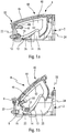
Figure 1a to 1c are cross-sectional views showing a first embodiment of a storage housing according to the invention respectively in a closed, partially open and fully position, -
Figure 2 is a cross-sectional view of a cover of the storage housing offigures 1a to 1c , -
Figure 3 is a perspective view partially showing in perspective the storage housing offigures 1a to 1c without a housing body thereof, -
Figure 4 is a side view partially showing of the storage housing offigures 1a to 1c , -
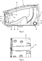
Figure 5 is a cross-sectional view of another embodiment of a storage housing according to the invention, -
Figure 6 is a perspective view showing the bottom part of the storage housing ofFigure 5 . - As illustrated in the
figures 1a to 1c , the invention relates to a storage housing. It is especially intended to contend glasses. In other words, the storage housing according to the invention is especially intended to be a glass box. - Said housing comprises a
body 2. Said body comprises for instancelateral walls 20, only one of them being visible on the figures, afront wall 22 and aback wall 24 all linked by abottom side 26 of saidbody 2. Saidbody 2 may also comprise anaesthetic frame 28 dissimulating free edges of saidlateral walls 20,front wall 22 andback wall 24. - Said housing further comprises a
cover 4 closing saidbody 2, more especially closing an aperture defined by saidaesthetic frame 28 and/or the free edges of saidlateral walls 20,front wall 22 andback wall 24. Saidcover 4 comprises aclosing part 40. Said closingpart 40 may comprise a supportingarmature 42 andaesthetic panel 44 fixed on said supportingarmature 42. Saidcover 4 further comprises afirst flange 46 extending from theclosing part 40 in parallel to one of saidlateral wall 20 called herein after first lateral wall. - The
aesthetic frame 28 and/or theaesthetic panel 44 may be made of a material nobler than the rest of the housing so as to improve the finish perceived by a user. - Said housing further comprises a
first lever 6 better visible onfigures 1b and1c . It is here located between the firstlateral wall 20 of thehousing body 2 and thefirst flange 46 of saidcover 4. - Said
first lever 6 is in relation with a degree of liberty in rotation with saidbody 2 along a fixedrotational axis 8. Said fixedrotational axis 8 is located within thehousing body 2. More precisely it is here located between the lateral walls which is to say below the body aperture. Saidfirst lever 6 is further in relation with a degree of liberty in rotation with saidcover 4 along a mobilerotational axis 10. In other words, the mobilerotational axis 10 pivots circularly around the fixedrotational axis 8. - However, said housing further comprises a
first cam 12 and afirst cam path 14 and it is configured so that saidfirst cam 12 moves along thefirst cam path 14 in response of an actuation of thefirst lever 6 to obtain a displacement of thecover 4 combining a pivoting movement and a lifting movement while thecover 4 remains partially inside thehousing body 2. - In other words, the
cover 4 and thehousing body 2 are not in relation with one another according to a fixed rotational axis. On the contrary the cover displacement is determined by the movement of the mobilerotational axis 10 together with the movement of thefirst cam 12 in thefirst cam path 14. Thanks to such cooperation, it is possible to obtain both a pivoting movement and a lifting movement of thecover 4 while having apart 16 thereof remaining inside thehousing body 2. It hence enables to open widely thecover 4 and to limit the space needed for the cover opening trajectory. Accordingly, glasses or other items can be more easily introduced inside the housing and the latter can more easily be located in areas where the available place is reduced. - In
figure 1a , thecover 4 is in a closing position in which thehousing body 2 is closed by saidcover 4. Thefirst lever 6 has an orientation which is approximatively vertical or slightly angularly shifted from the vertical, on the left on the figure. Thefirst cam 12 is located on afirst extremity 18 of thefirst cam path 14, the lower left extremity on the figures. - In
figure 1b , thecover 4 has moved counter clockwise and thehousing body 2 is partially open. Thefirst lever 6 has moved counter clockwise too and has an orientation which is angularly clearly shifted from the vertical, on the right on the figure. Thefirst cam 12 is located along thefirst cam path 14 on an intermediate position thereon. - In
figure 1c , thecover 4 is in an opening position. It has further moved counter clockwise. It is in an end of course configuration where it is totally open. Thefirst lever 6 has further moved counter clockwise too and has an orientation which is approximatively horizontal or slightly below under the horizontal. Thefirst cam 6 is located on asecond extremity 19 of thefirst cam path 14, the upper right extremity on the figure. - As illustrated on
figure 2 , saidfirst flange 46 advantageously, comprises a firstdistal bearing 50 in which saidlever 6 is articulated relatively to saidcover 4 around said mobilerotational axis 10. Said firstdistal bearing 50 is located on adistal side 52 of thefirst flange 46 opposite thecover closing part 40. It is here at a corner of saiddistal side 52 and afront side 54 of saidfirst flange 46. - Said first
lateral wall 20 comprises a first proximal bearing not shown in which saidfirst lever 6 is articulated around said fixedrotational axis 8. Said first proximal bearing is located in the vicinity of said cover closing part, just below the free edge of said firstlateral wall 20. - Advantageously, said
first cam path 14 is located on thehousing body 2. Saidfirst cam path 14 is for instance defined by afirst guiding groove 58, especially located on said firstlateral wall 20. As can be more easily seen onfigure 1c , saidfirst groove 58 is curved. It for instance follows a curve with a decreasing curvature between said closing and said open positions of thecover 4. It especially follows a portion of an ellipse. The firstproximal bearing 50 and hence the fixedrotational axis 8 are located in concave part of saidgroove 58. Here, saidfirst groove 58 is defined as a through hole. - Said
first cam 12 is located on thecover 4. It is here defined by a first movingpin 60 guided in saidfirst groove 58. For that purpose, saidfirst pin 60 extends transversally in direction of said firstlateral wall 20. - As can be best seen on
figure 2 , said first movingpin 60 is located on thedistal side 52 of thefirst flange 46 away from the firstdistal bearing 50 in a direction opposite saidfront side 54. Said first movingpin 60 has here a circular section. It follows tangentially opposite sides of saidgroove 58. - Going back to
figures 1a to 1c , it can be seen that saidfirst lever 6, saidfirst pin 60 and saidfirst groove 58 are configured so that said firstdistal bearing 50 and hence said mobilerotational axis 10 gets farther from thefirst groove 58 towards said concave part of saidgroove 58 when approaching the open position. Such movement is obtained thanks to the relative position of the firstdistal bearing 50 and thefirst pin 60 together with the curvature of thefirst groove 58. In such embodiment, it hence determines the cover displacement described above. - The configuration of the
housing body 2 and thecover 4 is preferentially symmetrical according to a median plan, parallel to the plan of thefigure 1a to 1c . - Accordingly, said
cover 4 further comprises a second flange symmetrical to thefirst flange 46 and extending from the closingpart 40 in parallel to the other of said lateral wall called herein after second lateral wall. - Said housing further comprises a second lever symmetrical to the
first lever 6. It is located between the second lateral wall of thehousing body 2 and the second flange of saidcover 4. - Said second flange comprises a second distal bearing symmetrical to the first
distal bearing 50, said second lever being articulated relatively to saidcover 4 around said mobilerotational axis 10 in said second distal bearing. Said second lateral wall comprises a second proximal bearing symmetrical to said first proximal bearing, said second lever being articulated around said fixedrotational axis 8 in said second proximal bearing. - Said housing further comprises a second cam and a second cam path which are respectively symmetrical to the
first cam 12 and thefirst cam path 14. Thanks to such symmetrical configuration, a more balanced cover displacement can be obtained. - Said second flange, second lever, second cam and second cam paths are not illustrated on the figures.
- As can be seen on
figure 3 , the housing further comprises ashaft 62. Saidfirst lever 6 and second levers are linked by saidshaft 62 to synchronize their movement. It can be for instance a metal shaft. Saidshaft 62 is located along said fixedrotational axis 8. - Said first and/or second levers respectively comprise a proximal end located in the corresponding proximal bearing. Said proximal end comprises a
proximal pin 64 projecting transversally along said fixedrotational axis 8, saidproximal pin 64 having a circular shape to pivot inside the corresponding proximal bearing around said fixedrotational axis 8. - Said
shaft 62 is linked to the first and second levers in the area of the proximal longitudinal ends thereof. More precisely saidshaft 62 is here linked in a centered manner to said proximal pins 64. Moreover said first and/or second flange comprise aslit 66 to let a passage for saidshaft 62. Said slit 66 is curved according to the relative displacement of thecover 4 and theshaft 62. - Going back to
figure 1a to 1c , saidshaft 62 is located in a longitudinal end of said slit 66 in the closed position. It is located close to an open longitudinal end of said slit 66 in the intermediate position. It is located outside said slit 66 in the opening position. - Said first and/or second levers further respectively comprise distal ends located in the corresponding
distal bearing 50. Said distal end comprises adistal pin 68 projecting transversally along said mobilerotational axis 10, saiddistal pin 68 having a circular shape to pivot inside the corresponding distal bearing around said mobilerotational axis 10. - As illustrated on
figure 3 ,5 and 6 , said housing comprises aspring 70, 70' actuating saidcover 4. - According to the embodiment illustrated on
figure 3 , said housing comprise afirst spring 70 located between said body, especially said first side wall, and saidfirst flange 46. More precisely it located in the vicinity of said first proximal bearing. Even more precisely, it is surrounding theproximal pin 64 corresponding to said first proximal bearing. One endingbranch 72 of thefirst spring 70 is linked to thelever 6 and the other opposite endingbranch 74 of thefirst spring 70 is linked to thehousing body 2, here its front wall. - To keep the symmetrical configuration of the housing mentioned above, it may comprise a second spring symmetrical to the
first spring 70. - According to the embodiment illustrated on
figure 5 and 6 , said housing comprises a single spring 70' actuating saidcover 4. Said spring 70' is here linked to a central part on the housing. Afirst end 76 of said spring 70' is fixed to saidshaft 62. Anotheropposite end 78 is fixed to saidbody 2. Said spring 70' comprise here a first 80 and a second 82 intermediate branch joining saidfirst end 76 and saidopposite end 78 thereof. Saidfirst branch 80 is extending in parallel of saidfront wall 22 and saidsecond branch 78 is extending in parallel of saidbottom wall 26. - Said
first end 76 of the spring 70' is sensibly parallel to said secondintermediate branch 82. It gives its spring effect to said spring 70'. Saidfirst end 76 of the spring 70' is joined to said firstintermediate branch 80 around afirst holding pin 84. Said firstintermediate branch 80 is joined to said secondintermediate branch 82 around asecond holding pin 86. Said opposite end of the spring 70' is located around athird holding pin 88. - As illustrated on
figure 4 , said housing advantageously comprises a brake smoothing said cover displacement. Said brake comprisesteeth wheels first teeth wheel 90 actuated by saidshaft 62 and asecond teeth wheel 92 which is fixed to thebody 2 on its firstlateral wall 20 and engaging saidfirst teeth wheel 90. Said second teeth wheel 92 is in a damping feature like silicon brake. - Said housing may further comprise any kind of cover switch as a push-type switch, not illustrated, thanks to which the user locks and unlocks the
cover 4. According to such kind of switch, when the cover is locked on its closed position (figure 1a ), a first pull actuation of the switch unlocks the cover and triggers its displacement toward the opening position (figure 1c ). When the user wants to close the cover, he or she guides it toward the closed position in which the switch relocks the cover. - The invention also relates to a
roof module 2 which is not illustrated. Said roof control module comprises a storage housing as described above. Said storage housing may hence comprise any of the technical features previously described. - The roof control module may be located on the ceiling of a car, between the two front seats and aligned with the central mirror. It may further comprise headlamps, sensors and/or control buttons corresponding to various functions to be actuated by the driver and/or the front passenger.
- The invention has been described above with the aid of embodiments shown in the figures, without limitation of the general inventive concept. Many other modifications and variations are suggested by those skilled in the art, after reflection on the various embodiments illustrated in this application. These embodiments are given by way of example and are not intended to limit the scope of the invention, which is determined exclusively by the claims below.
Claims (15)
- Storage housing, especially for glasses, said housing comprising a body (2) and a cover (4) closing said body (2), said housing further comprising a first cam (12), a first cam path (14) and a first lever (6), said first lever (6) being in relation with a degree of liberty in rotation with both said body (2) and said cover (4), said housing being configured so that said first cam (12) moves along the first cam path (14) in response of a first lever actuation to obtain a cover displacement combining a pivoting movement and a lifting movement while the cover (4) remains partially inside the housing body (2).
- Storage housing according to claim 1 wherein said first cam path (14) is located on the body (2).
- Storage housing according to any of claim 1 or 2 wherein said first cam path (14) is defined by a first guiding groove (58).
- Storage housing according to claim 3 wherein said first groove (58) follows a curve with a decreasing curvature between a closing and an open position of the cover (4).
- Storage housing according to any of claims 3 or 4 wherein said first cam (12) is defined by a first moving pin (60) guided in said first groove (58).
- Storage housing according to any of the preceding claims wherein said first cam (12) is located on the cover (4).
- Storage housing according to any of the preceding claims wherein said cover (4) comprises a closing part (40) and a first flange (46).
- Storage housing according to claim 7 wherein said first flange (46) comprises a first distal bearing (50) in which said first lever (6) is articulated.
- Storage housing according to claim 8 wherein said first distal bearing (50) is located on a distal side (52) of the first flange (46) opposite the cover closing part (40).
- Storage housing according to any of the preceding claims wherein said body (2) comprises a first proximal bearing in which said first lever (6) is articulated.
- Storage housing according to any of the preceding claims wherein said housing comprises a second cam, a second cam path and second lever which are respectively symmetrical to said first cam (12), said first cam path (14) and said first lever (6).
- Storage housing according to claim 11 wherein said first and second levers are linked by a shaft (62) to synchronize their movement.
- Storage housing according to claim 12 wherein said housing comprises a brake smoothing said displacement, said brake comprising teeth wheels (90, 92), a first teeth wheel (90) thereof being actuated by said shaft (62) and a second teeth wheel (92) thereof being fixed to the body (2) and engaging said first teeth wheel (90).
- Storage housing according to any of the preceding claims wherein said housing comprises a first spring (70, 70') actuating said cover (4).
- Roof module comprising a storage housing according to any of the preceding claims.
Priority Applications (1)
| Application Number | Priority Date | Filing Date | Title |
|---|---|---|---|
| EP17208692.8A EP3501901B1 (en) | 2017-12-19 | 2017-12-19 | Storage housing, especially for glasses, and roof module comprising such a storage housing |
Applications Claiming Priority (1)
| Application Number | Priority Date | Filing Date | Title |
|---|---|---|---|
| EP17208692.8A EP3501901B1 (en) | 2017-12-19 | 2017-12-19 | Storage housing, especially for glasses, and roof module comprising such a storage housing |
Publications (2)
| Publication Number | Publication Date |
|---|---|
| EP3501901A1 true EP3501901A1 (en) | 2019-06-26 |
| EP3501901B1 EP3501901B1 (en) | 2020-08-12 |
Family
ID=60702289
Family Applications (1)
| Application Number | Title | Priority Date | Filing Date |
|---|---|---|---|
| EP17208692.8A Active EP3501901B1 (en) | 2017-12-19 | 2017-12-19 | Storage housing, especially for glasses, and roof module comprising such a storage housing |
Country Status (1)
| Country | Link |
|---|---|
| EP (1) | EP3501901B1 (en) |
Citations (6)
| Publication number | Priority date | Publication date | Assignee | Title |
|---|---|---|---|---|
| WO1994018031A1 (en) * | 1993-02-15 | 1994-08-18 | Fischerwerke Artur Fischer Gmbh & Co. Kg | Motor vehicle inner rearview mirror with integrated glove box |
| JP2004175256A (en) * | 2002-11-28 | 2004-06-24 | Inoac Corp | Overhead console |
| KR100825402B1 (en) * | 2007-01-26 | 2008-04-29 | 쌍용자동차 주식회사 | Opening and closing device of glovebox for automobile |
| JP2008247134A (en) * | 2007-03-29 | 2008-10-16 | Calsonic Kansei Corp | Vehicular console box |
| JP2011152813A (en) * | 2010-01-26 | 2011-08-11 | Toyoda Gosei Co Ltd | Storage device for vehicle |
| DE102013020313A1 (en) * | 2013-12-04 | 2015-06-11 | Valeo Schalter Und Sensoren Gmbh | Storage compartment for a motor vehicle and motor vehicle with a storage compartment |
-
2017
- 2017-12-19 EP EP17208692.8A patent/EP3501901B1/en active Active
Patent Citations (6)
| Publication number | Priority date | Publication date | Assignee | Title |
|---|---|---|---|---|
| WO1994018031A1 (en) * | 1993-02-15 | 1994-08-18 | Fischerwerke Artur Fischer Gmbh & Co. Kg | Motor vehicle inner rearview mirror with integrated glove box |
| JP2004175256A (en) * | 2002-11-28 | 2004-06-24 | Inoac Corp | Overhead console |
| KR100825402B1 (en) * | 2007-01-26 | 2008-04-29 | 쌍용자동차 주식회사 | Opening and closing device of glovebox for automobile |
| JP2008247134A (en) * | 2007-03-29 | 2008-10-16 | Calsonic Kansei Corp | Vehicular console box |
| JP2011152813A (en) * | 2010-01-26 | 2011-08-11 | Toyoda Gosei Co Ltd | Storage device for vehicle |
| DE102013020313A1 (en) * | 2013-12-04 | 2015-06-11 | Valeo Schalter Und Sensoren Gmbh | Storage compartment for a motor vehicle and motor vehicle with a storage compartment |
Also Published As
| Publication number | Publication date |
|---|---|
| EP3501901B1 (en) | 2020-08-12 |
Similar Documents
| Publication | Publication Date | Title |
|---|---|---|
| US8713852B2 (en) | Invisible sliding door | |
| US8443553B1 (en) | Closure assembly with moveable cover and closeout for a retractable handle | |
| US9623804B2 (en) | Folding cargo compartment floor and vehicle rear-end structure | |
| US20110217914A1 (en) | Ventilation nozzle for the interior of a vehicle | |
| JP6483301B1 (en) | Slide device for automobile sunroof | |
| US10730371B2 (en) | Vehicular door | |
| US10814802B2 (en) | Vehicular door | |
| CN204527346U (en) | For the cap assemblies of striker, vehicle closure system and the lid for striker | |
| EP2979910A1 (en) | Roof assembly for a vehicle | |
| CN108215967B (en) | Center console armrest for vehicle | |
| EP3501901B1 (en) | Storage housing, especially for glasses, and roof module comprising such a storage housing | |
| US8141935B2 (en) | Door trim moving applique | |
| US20130088046A1 (en) | Motor vehicle, in particular passenger car | |
| US8042302B2 (en) | Window pane for a motor vehicle | |
| CN107531138B (en) | Pivotable motor vehicle rear cover | |
| CN105835733A (en) | Armrest device for auxiliary fascia console of automobile | |
| US8172299B2 (en) | Compartment door with force and effort control | |
| US20190162008A1 (en) | Vehicular door | |
| CN109070708A (en) | Component for roof | |
| JP4961487B2 (en) | Vehicle rearward confirmation device | |
| US9074388B2 (en) | Door handle arrangement on a motor vehicle | |
| US11053715B2 (en) | Securing handle for an openable side window | |
| JP2024506443A (en) | Bracket hinge device and passenger car equipped with the same | |
| US20160355159A1 (en) | Wiper arm | |
| EP2045137B1 (en) | Cover for a structural sill portion of a vehicle |
Legal Events
| Date | Code | Title | Description |
|---|---|---|---|
| PUAI | Public reference made under article 153(3) epc to a published international application that has entered the european phase |
Free format text: ORIGINAL CODE: 0009012 |
|
| STAA | Information on the status of an ep patent application or granted ep patent |
Free format text: STATUS: THE APPLICATION HAS BEEN PUBLISHED |
|
| AK | Designated contracting states |
Kind code of ref document: A1 Designated state(s): AL AT BE BG CH CY CZ DE DK EE ES FI FR GB GR HR HU IE IS IT LI LT LU LV MC MK MT NL NO PL PT RO RS SE SI SK SM TR |
|
| AX | Request for extension of the european patent |
Extension state: BA ME |
|
| STAA | Information on the status of an ep patent application or granted ep patent |
Free format text: STATUS: REQUEST FOR EXAMINATION WAS MADE |
|
| 17P | Request for examination filed |
Effective date: 20191112 |
|
| RBV | Designated contracting states (corrected) |
Designated state(s): AL AT BE BG CH CY CZ DE DK EE ES FI FR GB GR HR HU IE IS IT LI LT LU LV MC MK MT NL NO PL PT RO RS SE SI SK SM TR |
|
| RIC1 | Information provided on ipc code assigned before grant |
Ipc: B60R 7/08 20060101AFI20200310BHEP |
|
| GRAP | Despatch of communication of intention to grant a patent |
Free format text: ORIGINAL CODE: EPIDOSNIGR1 |
|
| STAA | Information on the status of an ep patent application or granted ep patent |
Free format text: STATUS: GRANT OF PATENT IS INTENDED |
|
| INTG | Intention to grant announced |
Effective date: 20200424 |
|
| GRAS | Grant fee paid |
Free format text: ORIGINAL CODE: EPIDOSNIGR3 |
|
| GRAA | (expected) grant |
Free format text: ORIGINAL CODE: 0009210 |
|
| STAA | Information on the status of an ep patent application or granted ep patent |
Free format text: STATUS: THE PATENT HAS BEEN GRANTED |
|
| AK | Designated contracting states |
Kind code of ref document: B1 Designated state(s): AL AT BE BG CH CY CZ DE DK EE ES FI FR GB GR HR HU IE IS IT LI LT LU LV MC MK MT NL NO PL PT RO RS SE SI SK SM TR |
|
| REG | Reference to a national code |
Ref country code: CH Ref legal event code: EP |
|
| REG | Reference to a national code |
Ref country code: IE Ref legal event code: FG4D |
|
| REG | Reference to a national code |
Ref country code: DE Ref legal event code: R096 Ref document number: 602017021482 Country of ref document: DE |
|
| REG | Reference to a national code |
Ref country code: AT Ref legal event code: REF Ref document number: 1301248 Country of ref document: AT Kind code of ref document: T Effective date: 20200915 |
|
| REG | Reference to a national code |
Ref country code: LT Ref legal event code: MG4D |
|
| REG | Reference to a national code |
Ref country code: NL Ref legal event code: MP Effective date: 20200812 |
|
| PG25 | Lapsed in a contracting state [announced via postgrant information from national office to epo] |
Ref country code: SE Free format text: LAPSE BECAUSE OF FAILURE TO SUBMIT A TRANSLATION OF THE DESCRIPTION OR TO PAY THE FEE WITHIN THE PRESCRIBED TIME-LIMIT Effective date: 20200812 Ref country code: BG Free format text: LAPSE BECAUSE OF FAILURE TO SUBMIT A TRANSLATION OF THE DESCRIPTION OR TO PAY THE FEE WITHIN THE PRESCRIBED TIME-LIMIT Effective date: 20201112 Ref country code: HR Free format text: LAPSE BECAUSE OF FAILURE TO SUBMIT A TRANSLATION OF THE DESCRIPTION OR TO PAY THE FEE WITHIN THE PRESCRIBED TIME-LIMIT Effective date: 20200812 Ref country code: LT Free format text: LAPSE BECAUSE OF FAILURE TO SUBMIT A TRANSLATION OF THE DESCRIPTION OR TO PAY THE FEE WITHIN THE PRESCRIBED TIME-LIMIT Effective date: 20200812 Ref country code: FI Free format text: LAPSE BECAUSE OF FAILURE TO SUBMIT A TRANSLATION OF THE DESCRIPTION OR TO PAY THE FEE WITHIN THE PRESCRIBED TIME-LIMIT Effective date: 20200812 Ref country code: GR Free format text: LAPSE BECAUSE OF FAILURE TO SUBMIT A TRANSLATION OF THE DESCRIPTION OR TO PAY THE FEE WITHIN THE PRESCRIBED TIME-LIMIT Effective date: 20201113 Ref country code: NO Free format text: LAPSE BECAUSE OF FAILURE TO SUBMIT A TRANSLATION OF THE DESCRIPTION OR TO PAY THE FEE WITHIN THE PRESCRIBED TIME-LIMIT Effective date: 20201112 |
|
| REG | Reference to a national code |
Ref country code: AT Ref legal event code: MK05 Ref document number: 1301248 Country of ref document: AT Kind code of ref document: T Effective date: 20200812 |
|
| PG25 | Lapsed in a contracting state [announced via postgrant information from national office to epo] |
Ref country code: IS Free format text: LAPSE BECAUSE OF FAILURE TO SUBMIT A TRANSLATION OF THE DESCRIPTION OR TO PAY THE FEE WITHIN THE PRESCRIBED TIME-LIMIT Effective date: 20201212 Ref country code: LV Free format text: LAPSE BECAUSE OF FAILURE TO SUBMIT A TRANSLATION OF THE DESCRIPTION OR TO PAY THE FEE WITHIN THE PRESCRIBED TIME-LIMIT Effective date: 20200812 Ref country code: NL Free format text: LAPSE BECAUSE OF FAILURE TO SUBMIT A TRANSLATION OF THE DESCRIPTION OR TO PAY THE FEE WITHIN THE PRESCRIBED TIME-LIMIT Effective date: 20200812 Ref country code: RS Free format text: LAPSE BECAUSE OF FAILURE TO SUBMIT A TRANSLATION OF THE DESCRIPTION OR TO PAY THE FEE WITHIN THE PRESCRIBED TIME-LIMIT Effective date: 20200812 Ref country code: PL Free format text: LAPSE BECAUSE OF FAILURE TO SUBMIT A TRANSLATION OF THE DESCRIPTION OR TO PAY THE FEE WITHIN THE PRESCRIBED TIME-LIMIT Effective date: 20200812 |
|
| PG25 | Lapsed in a contracting state [announced via postgrant information from national office to epo] |
Ref country code: CZ Free format text: LAPSE BECAUSE OF FAILURE TO SUBMIT A TRANSLATION OF THE DESCRIPTION OR TO PAY THE FEE WITHIN THE PRESCRIBED TIME-LIMIT Effective date: 20200812 Ref country code: DK Free format text: LAPSE BECAUSE OF FAILURE TO SUBMIT A TRANSLATION OF THE DESCRIPTION OR TO PAY THE FEE WITHIN THE PRESCRIBED TIME-LIMIT Effective date: 20200812 Ref country code: RO Free format text: LAPSE BECAUSE OF FAILURE TO SUBMIT A TRANSLATION OF THE DESCRIPTION OR TO PAY THE FEE WITHIN THE PRESCRIBED TIME-LIMIT Effective date: 20200812 Ref country code: SM Free format text: LAPSE BECAUSE OF FAILURE TO SUBMIT A TRANSLATION OF THE DESCRIPTION OR TO PAY THE FEE WITHIN THE PRESCRIBED TIME-LIMIT Effective date: 20200812 Ref country code: EE Free format text: LAPSE BECAUSE OF FAILURE TO SUBMIT A TRANSLATION OF THE DESCRIPTION OR TO PAY THE FEE WITHIN THE PRESCRIBED TIME-LIMIT Effective date: 20200812 |
|
| REG | Reference to a national code |
Ref country code: DE Ref legal event code: R097 Ref document number: 602017021482 Country of ref document: DE |
|
| PG25 | Lapsed in a contracting state [announced via postgrant information from national office to epo] |
Ref country code: AT Free format text: LAPSE BECAUSE OF FAILURE TO SUBMIT A TRANSLATION OF THE DESCRIPTION OR TO PAY THE FEE WITHIN THE PRESCRIBED TIME-LIMIT Effective date: 20200812 Ref country code: AL Free format text: LAPSE BECAUSE OF FAILURE TO SUBMIT A TRANSLATION OF THE DESCRIPTION OR TO PAY THE FEE WITHIN THE PRESCRIBED TIME-LIMIT Effective date: 20200812 Ref country code: ES Free format text: LAPSE BECAUSE OF FAILURE TO SUBMIT A TRANSLATION OF THE DESCRIPTION OR TO PAY THE FEE WITHIN THE PRESCRIBED TIME-LIMIT Effective date: 20200812 |
|
| PLBE | No opposition filed within time limit |
Free format text: ORIGINAL CODE: 0009261 |
|
| STAA | Information on the status of an ep patent application or granted ep patent |
Free format text: STATUS: NO OPPOSITION FILED WITHIN TIME LIMIT |
|
| PG25 | Lapsed in a contracting state [announced via postgrant information from national office to epo] |
Ref country code: SK Free format text: LAPSE BECAUSE OF FAILURE TO SUBMIT A TRANSLATION OF THE DESCRIPTION OR TO PAY THE FEE WITHIN THE PRESCRIBED TIME-LIMIT Effective date: 20200812 |
|
| 26N | No opposition filed |
Effective date: 20210514 |
|
| PG25 | Lapsed in a contracting state [announced via postgrant information from national office to epo] |
Ref country code: IT Free format text: LAPSE BECAUSE OF FAILURE TO SUBMIT A TRANSLATION OF THE DESCRIPTION OR TO PAY THE FEE WITHIN THE PRESCRIBED TIME-LIMIT Effective date: 20200812 |
|
| REG | Reference to a national code |
Ref country code: CH Ref legal event code: PL |
|
| PG25 | Lapsed in a contracting state [announced via postgrant information from national office to epo] |
Ref country code: SI Free format text: LAPSE BECAUSE OF FAILURE TO SUBMIT A TRANSLATION OF THE DESCRIPTION OR TO PAY THE FEE WITHIN THE PRESCRIBED TIME-LIMIT Effective date: 20200812 Ref country code: MC Free format text: LAPSE BECAUSE OF FAILURE TO SUBMIT A TRANSLATION OF THE DESCRIPTION OR TO PAY THE FEE WITHIN THE PRESCRIBED TIME-LIMIT Effective date: 20200812 |
|
| REG | Reference to a national code |
Ref country code: BE Ref legal event code: MM Effective date: 20201231 |
|
| PG25 | Lapsed in a contracting state [announced via postgrant information from national office to epo] |
Ref country code: LU Free format text: LAPSE BECAUSE OF NON-PAYMENT OF DUE FEES Effective date: 20201219 Ref country code: IE Free format text: LAPSE BECAUSE OF NON-PAYMENT OF DUE FEES Effective date: 20201219 |
|
| PG25 | Lapsed in a contracting state [announced via postgrant information from national office to epo] |
Ref country code: CH Free format text: LAPSE BECAUSE OF NON-PAYMENT OF DUE FEES Effective date: 20201231 Ref country code: LI Free format text: LAPSE BECAUSE OF NON-PAYMENT OF DUE FEES Effective date: 20201231 |
|
| PG25 | Lapsed in a contracting state [announced via postgrant information from national office to epo] |
Ref country code: TR Free format text: LAPSE BECAUSE OF FAILURE TO SUBMIT A TRANSLATION OF THE DESCRIPTION OR TO PAY THE FEE WITHIN THE PRESCRIBED TIME-LIMIT Effective date: 20200812 Ref country code: MT Free format text: LAPSE BECAUSE OF FAILURE TO SUBMIT A TRANSLATION OF THE DESCRIPTION OR TO PAY THE FEE WITHIN THE PRESCRIBED TIME-LIMIT Effective date: 20200812 Ref country code: CY Free format text: LAPSE BECAUSE OF FAILURE TO SUBMIT A TRANSLATION OF THE DESCRIPTION OR TO PAY THE FEE WITHIN THE PRESCRIBED TIME-LIMIT Effective date: 20200812 |
|
| PG25 | Lapsed in a contracting state [announced via postgrant information from national office to epo] |
Ref country code: MK Free format text: LAPSE BECAUSE OF FAILURE TO SUBMIT A TRANSLATION OF THE DESCRIPTION OR TO PAY THE FEE WITHIN THE PRESCRIBED TIME-LIMIT Effective date: 20200812 |
|
| PG25 | Lapsed in a contracting state [announced via postgrant information from national office to epo] |
Ref country code: PT Free format text: LAPSE BECAUSE OF FAILURE TO SUBMIT A TRANSLATION OF THE DESCRIPTION OR TO PAY THE FEE WITHIN THE PRESCRIBED TIME-LIMIT Effective date: 20200812 Ref country code: BE Free format text: LAPSE BECAUSE OF NON-PAYMENT OF DUE FEES Effective date: 20201231 |
|
| GBPC | Gb: european patent ceased through non-payment of renewal fee |
Effective date: 20211219 |
|
| PG25 | Lapsed in a contracting state [announced via postgrant information from national office to epo] |
Ref country code: GB Free format text: LAPSE BECAUSE OF NON-PAYMENT OF DUE FEES Effective date: 20211219 |
|
| P01 | Opt-out of the competence of the unified patent court (upc) registered |
Effective date: 20230528 |
|
| PGFP | Annual fee paid to national office [announced via postgrant information from national office to epo] |
Ref country code: FR Payment date: 20231220 Year of fee payment: 7 Ref country code: DE Payment date: 20231208 Year of fee payment: 7 |