EP3501875B1 - Traktionsnetz in einem elektrofahrzeug - Google Patents
Traktionsnetz in einem elektrofahrzeug Download PDFInfo
- Publication number
- EP3501875B1 EP3501875B1 EP18212015.4A EP18212015A EP3501875B1 EP 3501875 B1 EP3501875 B1 EP 3501875B1 EP 18212015 A EP18212015 A EP 18212015A EP 3501875 B1 EP3501875 B1 EP 3501875B1
- Authority
- EP
- European Patent Office
- Prior art keywords
- filter
- active
- voltage line
- traction network
- voltage
- Prior art date
- Legal status (The legal status is an assumption and is not a legal conclusion. Google has not performed a legal analysis and makes no representation as to the accuracy of the status listed.)
- Active
Links
Images




Classifications
-
- H—ELECTRICITY
- H02—GENERATION; CONVERSION OR DISTRIBUTION OF ELECTRIC POWER
- H02M—APPARATUS FOR CONVERSION BETWEEN AC AND AC, BETWEEN AC AND DC, OR BETWEEN DC AND DC, AND FOR USE WITH MAINS OR SIMILAR POWER SUPPLY SYSTEMS; CONVERSION OF DC OR AC INPUT POWER INTO SURGE OUTPUT POWER; CONTROL OR REGULATION THEREOF
- H02M1/00—Details of apparatus for conversion
- H02M1/14—Arrangements for reducing ripples from DC input or output
-
- B—PERFORMING OPERATIONS; TRANSPORTING
- B60—VEHICLES IN GENERAL
- B60L—PROPULSION OF ELECTRICALLY-PROPELLED VEHICLES; SUPPLYING ELECTRIC POWER FOR AUXILIARY EQUIPMENT OF ELECTRICALLY-PROPELLED VEHICLES; ELECTRODYNAMIC BRAKE SYSTEMS FOR VEHICLES IN GENERAL; MAGNETIC SUSPENSION OR LEVITATION FOR VEHICLES; MONITORING OPERATING VARIABLES OF ELECTRICALLY-PROPELLED VEHICLES; ELECTRIC SAFETY DEVICES FOR ELECTRICALLY-PROPELLED VEHICLES
- B60L3/00—Electric devices on electrically-propelled vehicles for safety purposes; Monitoring operating variables, e.g. speed, deceleration or energy consumption
- B60L3/0023—Detecting, eliminating, remedying or compensating for drive train abnormalities, e.g. failures within the drive train
-
- B—PERFORMING OPERATIONS; TRANSPORTING
- B60—VEHICLES IN GENERAL
- B60L—PROPULSION OF ELECTRICALLY-PROPELLED VEHICLES; SUPPLYING ELECTRIC POWER FOR AUXILIARY EQUIPMENT OF ELECTRICALLY-PROPELLED VEHICLES; ELECTRODYNAMIC BRAKE SYSTEMS FOR VEHICLES IN GENERAL; MAGNETIC SUSPENSION OR LEVITATION FOR VEHICLES; MONITORING OPERATING VARIABLES OF ELECTRICALLY-PROPELLED VEHICLES; ELECTRIC SAFETY DEVICES FOR ELECTRICALLY-PROPELLED VEHICLES
- B60L3/00—Electric devices on electrically-propelled vehicles for safety purposes; Monitoring operating variables, e.g. speed, deceleration or energy consumption
- B60L3/0023—Detecting, eliminating, remedying or compensating for drive train abnormalities, e.g. failures within the drive train
- B60L3/0069—Detecting, eliminating, remedying or compensating for drive train abnormalities, e.g. failures within the drive train relating to the isolation, e.g. ground fault or leak current
-
- B—PERFORMING OPERATIONS; TRANSPORTING
- B60—VEHICLES IN GENERAL
- B60L—PROPULSION OF ELECTRICALLY-PROPELLED VEHICLES; SUPPLYING ELECTRIC POWER FOR AUXILIARY EQUIPMENT OF ELECTRICALLY-PROPELLED VEHICLES; ELECTRODYNAMIC BRAKE SYSTEMS FOR VEHICLES IN GENERAL; MAGNETIC SUSPENSION OR LEVITATION FOR VEHICLES; MONITORING OPERATING VARIABLES OF ELECTRICALLY-PROPELLED VEHICLES; ELECTRIC SAFETY DEVICES FOR ELECTRICALLY-PROPELLED VEHICLES
- B60L3/00—Electric devices on electrically-propelled vehicles for safety purposes; Monitoring operating variables, e.g. speed, deceleration or energy consumption
- B60L3/0023—Detecting, eliminating, remedying or compensating for drive train abnormalities, e.g. failures within the drive train
- B60L3/0084—Detecting, eliminating, remedying or compensating for drive train abnormalities, e.g. failures within the drive train relating to control modules
-
- H—ELECTRICITY
- H02—GENERATION; CONVERSION OR DISTRIBUTION OF ELECTRIC POWER
- H02J—ELECTRIC POWER NETWORKS; CIRCUIT ARRANGEMENTS OR SYSTEMS FOR SUPPLYING OR DISTRIBUTING ELECTRIC POWER; SYSTEMS FOR STORING ELECTRIC ENERGY
- H02J1/00—Circuit arrangements for DC mains or DC distribution networks
- H02J1/02—Arrangements for reducing harmonics or ripples
-
- H—ELECTRICITY
- H02—GENERATION; CONVERSION OR DISTRIBUTION OF ELECTRIC POWER
- H02J—ELECTRIC POWER NETWORKS; CIRCUIT ARRANGEMENTS OR SYSTEMS FOR SUPPLYING OR DISTRIBUTING ELECTRIC POWER; SYSTEMS FOR STORING ELECTRIC ENERGY
- H02J7/00—Circuit arrangements for charging or discharging batteries or for supplying loads from batteries
- H02J7/855—Circuit arrangements for charging or discharging batteries or for supplying loads from batteries with circuits adapted for supplying loads from the battery
-
- H—ELECTRICITY
- H02—GENERATION; CONVERSION OR DISTRIBUTION OF ELECTRIC POWER
- H02M—APPARATUS FOR CONVERSION BETWEEN AC AND AC, BETWEEN AC AND DC, OR BETWEEN DC AND DC, AND FOR USE WITH MAINS OR SIMILAR POWER SUPPLY SYSTEMS; CONVERSION OF DC OR AC INPUT POWER INTO SURGE OUTPUT POWER; CONTROL OR REGULATION THEREOF
- H02M1/00—Details of apparatus for conversion
- H02M1/12—Arrangements for reducing harmonics from AC input or output
-
- H—ELECTRICITY
- H02—GENERATION; CONVERSION OR DISTRIBUTION OF ELECTRIC POWER
- H02M—APPARATUS FOR CONVERSION BETWEEN AC AND AC, BETWEEN AC AND DC, OR BETWEEN DC AND DC, AND FOR USE WITH MAINS OR SIMILAR POWER SUPPLY SYSTEMS; CONVERSION OF DC OR AC INPUT POWER INTO SURGE OUTPUT POWER; CONTROL OR REGULATION THEREOF
- H02M1/00—Details of apparatus for conversion
- H02M1/14—Arrangements for reducing ripples from DC input or output
- H02M1/15—Arrangements for reducing ripples from DC input or output using active elements
-
- H—ELECTRICITY
- H02—GENERATION; CONVERSION OR DISTRIBUTION OF ELECTRIC POWER
- H02M—APPARATUS FOR CONVERSION BETWEEN AC AND AC, BETWEEN AC AND DC, OR BETWEEN DC AND DC, AND FOR USE WITH MAINS OR SIMILAR POWER SUPPLY SYSTEMS; CONVERSION OF DC OR AC INPUT POWER INTO SURGE OUTPUT POWER; CONTROL OR REGULATION THEREOF
- H02M1/00—Details of apparatus for conversion
- H02M1/44—Circuits or arrangements for compensating for electromagnetic interference in converters or inverters
-
- H—ELECTRICITY
- H02—GENERATION; CONVERSION OR DISTRIBUTION OF ELECTRIC POWER
- H02J—ELECTRIC POWER NETWORKS; CIRCUIT ARRANGEMENTS OR SYSTEMS FOR SUPPLYING OR DISTRIBUTING ELECTRIC POWER; SYSTEMS FOR STORING ELECTRIC ENERGY
- H02J2105/00—Networks for supplying or distributing electric power characterised by their spatial reach or by the load
- H02J2105/30—Networks for supplying or distributing electric power characterised by their spatial reach or by the load the load networks being external to vehicles, i.e. exchanging power with vehicles
- H02J2105/33—Networks for supplying or distributing electric power characterised by their spatial reach or by the load the load networks being external to vehicles, i.e. exchanging power with vehicles exchanging power with road vehicles
- H02J2105/37—Networks for supplying or distributing electric power characterised by their spatial reach or by the load the load networks being external to vehicles, i.e. exchanging power with vehicles exchanging power with road vehicles exchanging power with electric vehicles [EV] or with hybrid electric vehicles [HEV]
-
- H—ELECTRICITY
- H02—GENERATION; CONVERSION OR DISTRIBUTION OF ELECTRIC POWER
- H02M—APPARATUS FOR CONVERSION BETWEEN AC AND AC, BETWEEN AC AND DC, OR BETWEEN DC AND DC, AND FOR USE WITH MAINS OR SIMILAR POWER SUPPLY SYSTEMS; CONVERSION OF DC OR AC INPUT POWER INTO SURGE OUTPUT POWER; CONTROL OR REGULATION THEREOF
- H02M1/00—Details of apparatus for conversion
- H02M1/12—Arrangements for reducing harmonics from AC input or output
- H02M1/123—Suppression of common mode voltage or current
-
- H—ELECTRICITY
- H02—GENERATION; CONVERSION OR DISTRIBUTION OF ELECTRIC POWER
- H02M—APPARATUS FOR CONVERSION BETWEEN AC AND AC, BETWEEN AC AND DC, OR BETWEEN DC AND DC, AND FOR USE WITH MAINS OR SIMILAR POWER SUPPLY SYSTEMS; CONVERSION OF DC OR AC INPUT POWER INTO SURGE OUTPUT POWER; CONTROL OR REGULATION THEREOF
- H02M1/00—Details of apparatus for conversion
- H02M1/12—Arrangements for reducing harmonics from AC input or output
- H02M1/126—Arrangements for reducing harmonics from AC input or output using passive filters
-
- H—ELECTRICITY
- H03—ELECTRONIC CIRCUITRY
- H03H—IMPEDANCE NETWORKS, e.g. RESONANT CIRCUITS; RESONATORS
- H03H7/00—Multiple-port networks comprising only passive electrical elements as network components
- H03H7/42—Networks for transforming balanced signals into unbalanced signals and vice versa, e.g. baluns
- H03H7/425—Balance-balance networks
- H03H7/427—Common-mode filters
Definitions
- the invention relates to a traction network in an electric vehicle.
- the high voltage level of power electronic components in electric vehicles causes increased emissions.
- the common-mode interference pulses or common-mode interference (CM) on the lines between the inverter and the high-voltage battery are responsible for increased emissions. This is particularly critical because there are more structures that can be emitted on the DC side.
- EMC filters These usually consist of capacitive elements, which short-circuit the interference near the source, or inductive elements, which increase the impedance of the interference path.
- Y capacitors are primarily used between the HV lines and the vehicle ground. Since these are components of the insulation of the HV system, they are safety-critical, so that special requirements apply here. According to ISO 6469-3, the energy stored in the capacitor must be limited to a value of 200 mJ. With a 400 V high-voltage system, this corresponds to a total Y capacity in the vehicle of only 2.5 ⁇ F.
- an active filter comprising a coupling element made up of at least two capacitors which are connected in series between the positive high-voltage line and the negative high-voltage line, one Voltage amplifier, a current amplifier and a decoupling element.
- the decoupling element consists of at least two series-connected capacitors, which are arranged between the positive high-voltage line and the negative high-voltage line, the current amplifier having a push-pull stage, ie having two complementary transistors at the output.
- the EP 3 255 770 A1 discloses an arrangement comprising a battery and an inverter, which are connected to one another via a positive high-voltage line and a negative high-voltage line, with at least one active filter for reducing common-mode interference pulses being arranged between the positive high-voltage line and the negative high-voltage line, with between the battery and the active filter at least one passive common mode filter is arranged.
- a potential-free DC voltage network in particular a traction network of an electric or hybrid vehicle, comprising a DC voltage source, an inverter and at least one electrical consumer connected to the inverter, with at least one parasitic capacitance being formed between the electrical consumer and ground, with the direct voltage source and a common mode inductance is arranged on the inverter.
- a method for functional testing of electrical filters is known, a signal being introduced in the area of an input of the filter and a result signal being detected in the area of the output of the filter.
- An evaluation unit compares the result signal with an expected signal, a malfunction of the filter being detected in the event of a minimum deviation.
- the invention is based on the technical problem of creating a traction network for an electric vehicle in which the common-mode interference pulses are suppressed in an improved manner.
- the traction network in an electric vehicle comprises a traction battery and an inverter, which are connected to one another via a positive high-voltage line and a negative high-voltage line, with at least one active filter for reducing common-mode interference pulses being arranged between the positive high-voltage line and the negative high-voltage line, with at least one active filter being arranged between the traction battery and at least one passive common-mode filter is arranged in the active filter.
- the passive filter itself can be of simple construction, since it is only intended to suppress the interference pulses in the high frequency range of, for example, 2 MHz to 108 MHz, whereas in the frequency range of 100 kHz up to 2 MHz the suppression is primarily carried out by the active filter.
- the required inductances and / or capacitances are low, so that both the costs and the installation space of the passive filter are low compared to a complete compensation by means of a passive filter over the entire frequency range.
- the passive common-mode filter is constructed in several parts and has inductive and capacitive elements, with a Y capacitor between the positive and negative high-voltage line and ground being arranged between two inductive elements.
- the resulting T-structure has proven to be particularly suitable.
- the inductive elements are designed as ferrite rings. It is provided that the high-voltage lines are only passed through the ferrite rings, that is, are not wound around them, which extremely simplifies production.
- the active filter has an input stage, a preamplifier and an output amplifier.
- the active filter has an active HF filter and an active LF filter. This also enables an optimized adaptation to the respective frequency ranges with regard to the choice of components. However, this requires a relatively large number of components.
- the active filter can therefore also be designed as a combined HF / LF filter.
- a further passive filter which is preferably designed as a ferrite ring, is arranged between the active filter and the inverter. This has the advantage that the interference pulses are suppressed directly at the point of origin. It can also be provided here that the high-voltage lines are only passed through the ferrite ring.
- a traction network 1 is shown in a first embodiment.
- the traction network 1 comprises a traction battery 2 and an inverter 3 to which an electric motor 4 is connected.
- the traction battery 2 and the inverter 3 are connected to one another via a positive high-voltage line HV + and a negative high-voltage line HV-.
- the traction network 1 also has an active filter 5, which consists of an active HF filter 6 and an active LF filter 7.
- a first passive common mode filter 8 is arranged between the active filter 5 and the traction battery 2.
- Another passive common mode filter 9 is arranged between the active filter 5 and the inverter 3.
- the passive common mode filter 8 has a first inductive element L1 and a second inductive element L2, both of which are designed as ferrite rings.
- a capacitor C Y1 , C Y2 is arranged between the two inductive elements L1, L2 and is arranged between the positive high-voltage line HV + or the negative high-voltage line HV- and ground, so that a T-structure is created.
- the active filter 5 has an input stage 10, a preamplifier 11 and an output amplifier 12 or output stage, the signals being coupled in through input capacitors C IN and coupled out through output capacitors C OUT.
- the input and output capacitors C IN , C OUT can be formed by several capacitors connected in parallel.
- a possible embodiment of an RF amplifier 11 is shown.
- the input signal U in wid coupled through the two capacitors C6, C11 and through a Push-pull stage from the two complementary transistors Q1, Q2 amplified and inverted.
- the output signal U out for the output amplifier 12 is then made available via the decoupling capacitors C12, C1.
- the two junction FETs J1, J2 together with the resistors R5, R8 and R3, R14 each form a current source in order to set the operating points of the push-pull stage in a temperature-stabilized manner. Floating of the potential is prevented via the resistor R4.
- the supply voltage V +, V- is decoupled via the capacitors C2, C9.
- the two capacitors C2, C9 form a fast energy source for charge reversal processes in the transistors Q1, Q2 of the push-pull stage.
- an RF output amplifier 12 is shown.
- the output voltage U out of the preamplifier 11 is capacitively coupled in as input voltage U in via the capacitors C14, C15 and amplified via eight push-pull stages.
- the emitter resistors of the transistors of the push-pull stages (also marked with R out ) are used for stabilization in order to reduce the tendency to oscillate.
- the two junction FETs J3, J4 work again as a current source in order to set the operating points of the push-pull transistors in a temperature-stabilized manner.
- a circuit arrangement for an LF preamplifier 11 is shown, which is similar to the RF amplifier 11 according to FIG Fig. 4 is structured so that reference can be made to the description there.
- LF output stage 12 In the Fig. 7 an LF output stage 12 is shown, which largely corresponds to the circuit according to Fig. 5 is equivalent to.
- the main difference is that not a capacitor is used to decouple the supply voltage V +, V-, but a capacitor pair C14, C16 or C1, C2, the capacitors C14, C16 or C1, C2 of a capacitor pair being connected in parallel.
- one capacitor of a capacitor pair is many times smaller than the other capacitor.
- the factor is between 20-30, for example.
- the small capacitor is faster due to the low parasitic inductance, particularly at higher frequencies.
- the size is less critical with regard to the capacity, since the interference powers are smaller in the higher frequency range.
- an active HF filter 6 and an active LF filter 7 are that the components can be optimally adapted to their respective frequency ranges, for example 0.5 MHz to 5 MHz for HF and 0.1 MHz to 0.5 MHz for LF .
- the disadvantage is the increased number of components.
- FIG. 8 a block diagram of an alternative traction network 1 with a combined HF / LF filter 13 is shown.
- Fig. 10 an HF preamplifier 11 of the HF / LF filter 13 is shown, with regard to the circuit on Fig. 4 can be referenced.
- a further pair of capacitors C3, C4 is provided, which are connected in parallel and are arranged between the collectors of the push-pull stages.
- one capacitor has a capacitance that is many times higher than that of the other capacitor, so that the smaller capacitor is available for fast recharging processes in the HF range.
- the advantage of an active combined HF-LF filter 13 is the small installation space, the reduction in components and the fast HF preamplifier. Since only the supply voltage is filtered in the input stage, there is only a slight time offset between the interference and compensation signals. The somewhat poorer filter effect in the HF range can be compensated for by appropriately dimensioning the passive common-mode filters 8, 9.
Landscapes
- Engineering & Computer Science (AREA)
- Power Engineering (AREA)
- Life Sciences & Earth Sciences (AREA)
- Sustainable Development (AREA)
- Sustainable Energy (AREA)
- Transportation (AREA)
- Mechanical Engineering (AREA)
- Physics & Mathematics (AREA)
- Electromagnetism (AREA)
- Filters And Equalizers (AREA)
- Networks Using Active Elements (AREA)
Description
- Die Erfindung betrifft ein Traktionsnetz in einem Elektrofahrzeug.
- Die hohe Spannungslage leistungselektronischer Komponenten in Elektrofahrzeugen bedingt eine erhöhte Störaussendung. Dabei sind insbesondere die Gleichtaktstörimpulse bzw. die Common-Mode-Störungen (CM) auf den Leitungen zwischen Wechselrichter und Hochvolt-Batterie für eine erhöhte Störaussendung verantwortlich. Dies ist vor allem kritisch, da auf der DC-Seite mehr abstrahlfähige Strukturen vorhanden sind.
- Mit Hilfe von EMV-Filtern kann diesen Störungen entgegengewirkt werden. Diese bestehen üblicherweise aus kapazitiven Elementen, welche die Störungen nahe der Quelle kurzschließen bzw. induktiven Elementen, welche die Impedanz des Störpfades erhöhen. Um CM-Störungen in Elektrofahrzeugen zu reduzieren, werden primär Y-Kondensatoren zwischen den HV-Leitungen und der Fahrzeugmasse eingesetzt. Da diese Bestandteile der Isolation des HV-Systems sind, sind sie sicherheitskritisch, sodass hier besondere Anforderungen gelten. Gemäß ISO 6469-3 ist die im Kondensator gespeicherte Energie auf einen Wert von 200 mJ zu begrenzen. Bei einem 400-V-Hochvoltsystem entspricht dies einer gesamten Y-Kapazität im Fahrzeug von nur 2,5 µF.
- Reichen diese Maßnahmen nicht aus, kann die Störung mit Hilfe von induktiven Elementen in Form von CM-Drosseln entgegengewirkt werden. Diese Maßnahme ist aber sowohl kosten- als auch bauraumintensiv.
- In dem Fachartikel "Aktive EMI-Filter zur Reduktion von CM-Störimpulsen auf den HV-Leitungen von Elektrofahrzeugen", präsentiert auf der 7. GMM Fachtagung "EMV im KFZ", 20.09.2017 in Wolfsburg, wird zur Lösung dieses Problems die Verwendung aktiver Filterschaltungen vorgeschlagen.
- Dabei wird insbesondere ein aktiver Filter vorgeschlagen, umfassend ein Einkoppelglied aus mindestens zwei Kondensatoren, die in Reihe geschaltet zwischen der positiven Hochvoltleitung und der negativen Hochvoltleitung angeordnet sind, einen Spannungsverstärker, einen Stromverstärker und ein Auskoppelglied. Das Auskoppelglied besteht aus mindestens zwei in Reihe geschalteten Kondensatoren, die zwischen der positiven Hochvoltleitung und der negativen Hochvoltleitung angeordnet sind, wobei der Stromverstärker eine Push-Pull-Stufe aufweist, d.h. zwei komplementäre Transistoren am Ausgang aufweist.
- Die
EP 3 255 770 A1 offenbart eine Anordnung, umfassend eine Batterie und einen Wechselrichter, die über eine positive Hochvoltleitung und eine negative Hochvoltleitung miteinander verbunden sind, wobei zwischen der positiven Hochvoltleitung und der negativen Hochvoltleitung mindestens ein aktiver Filter zur Reduktion von Gleichtaktstörungspulsen angeordnet ist, wobei zwischen der Batterie und dem aktiven Filter mindestens ein passiver Gleichtaktfilter angeordnet ist. - Aus der
DE 10 2014 209 143 A1 ist ein potentialfreies Gleichspannungsnetz, insbesondere ein Traktionsnetz eines Elektro- oder Hybridfahrzeugs, bekannt, umfassend eine Gleichspannungsquelle, einen Wechselrichter sowie mindestens einen an den Wechselrichter angeschlossenen elektrischen Verbraucher, wobei zwischen dem elektrischen Verbraucher und Masse sich mindestens eine parasitäre Kapazität ausbildet, wobei zwischen der Gleichspannungsquelle und dem Wechselrichter eine Gleichtaktinduktivität angeordnet ist. - Aus der
DE 10 2009 056 395 A1 ist ein Verfahren zur Funktionsprüfung von elektrischen Filtern bekannt, wobei im Bereich eines Eingangs des Filters ein Signal eingeleitet sowie im Bereich des Ausgangs des Filters ein Resultatsignal erfasst wird. Eine Auswertungseinheit vergleicht das Resultatsignal mit einem Erwartungssignal, wobei bei einer Mindestabweichung eine Fehlfunktion des Filters detektiert wird. - Aus der
US 2006/0158814 A1 und derUS 3,996,857 A sind weitere passive Gleichtaktfilter bekannt. - Der Erfindung liegt das technische Problem zugrunde, ein Traktionsnetz für ein Elektrofahrzeug zu schaffen, bei dem die Gleichtaktstörimpulse verbessert unterdrückt werden.
- Die Lösung des technischen Problems ergibt sich durch ein Traktionsnetz mit den Merkmalen des Anspruchs 1. Weitere vorteilhafte Ausgestaltungen der Erfindung ergeben sich aus den Unteransprüchen.
- Hierzu umfasst das Traktionsnetz in einem Elektrofahrzeug eine Traktionsbatterie und einen Wechselrichter, die über eine positive Hochvoltleitung und eine negative Hochvoltleitung miteinander verbunden sind, wobei zwischen der positiven Hochvoltleitung und der negativen Hochvoltleitung mindestens ein aktiver Filter zur Reduktion von Gleichtaktstörimpulsen angeordnet ist, wobei zwischen der Traktionsbatterie und dem aktiven Filter mindestens ein passiver Gleichtaktfilter angeordnet ist. Hierdurch wird erreicht, dass die Anforderungen an die Spannungsfestigkeit des aktiven Filters herabgesetzt werden, wobei der passive Filter selbst einfach aufgebaut sein kann, da dieser nur die Störimpulse im hohen Frequenzbereich von beispielsweise 2 MHz bis 108 MHz unterdrücken soll, wohingegen im Frequenzbereich von 100 kHz bis 2 MHz die Unterdrückung primär durch den aktiven Filter erfolgt. Bei den hohen Frequenzen von 2 MHz und größer sind die benötigten Induktivitäten und/oder Kapazitäten gering, sodass sowohl Kosten und Bauraum des passiven Filters gering sind im Vergleich zu einer vollständigen Kompensation mittels eines passiven Filters über den ganzen Frequenzbereich.
- Dabei ist der passive Gleichtaktfilter mehrteilig ausgebildet und weist induktive und kapazitive Elemente auf, wobei zwischen zwei induktiven Elementen jeweils ein Y-Kondensator zwischen der positiven und der negativen Hochvoltleitung und Masse angeordnet ist. Die so entstehende T-Struktur hat sich als besonders geeignet erwiesen. Die induktiven Elemente sind dabei als Ferritringe ausgebildet. Dabei ist vorgesehen, dass die Hochvoltleitungen durch die Ferritringe nur durchgeführt sind, also nicht um diese gewickelt sind, was die Herstellung extrem vereinfacht.
- In einer Ausführungsform weist der aktive Filter eine Eingangsstufe, einen Vorverstärker und einen Endverstärker auf.
- In einer weiteren Ausführungsform weist der aktive Filter einen aktiven HF-Filter und einen aktiven LF-Filter auf. Dies ermöglicht auch hinsichtlich der Wahl der Bauelemente eine optimierte Anpassung an die jeweiligen Frequenzbereiche. Allerdings benötigt dies relativ viele Bauelemente.
- Alternativ kann daher der aktive Filter auch als kombinierter HF/LF-Filter ausgebildet sein.
- In einer weiteren Ausführungsform ist zwischen dem aktiven Filter und dem Wechselrichter ein weiterer passiver Filter angeordnet, der vorzugsweise als Ferritring ausgebildet ist. Dies hat den Vorteil, dass die Unterdrückung der Störimpulse direkt am Entstehungsort erfolgt. Dabei kann auch hier vorgesehen sein, dass die Hochvoltleitungen nur durch den Ferritring durchgeführt sind.
- Die Erfindung wird nachfolgend anhand eines bevorzugten Ausführungsbeispiels näher erläutert. Die Figuren zeigen:
- Fig. 1
- ein schematisches Blockschaltbild eines Traktionsnetzes in einer ersten Ausführungsform,
- Fig. 2
- eine Schaltung eines ersten passiven Gleichtaktfilters,
- Fig. 3
- ein schematisches Blockschaltbild eines aktiven Filters,
- Fig. 4
- eine Schaltung eines HF-Vorverstärkers,
- Fig. 5
- eine Schaltung einer HF-Endstufe,
- Fig. 6
- eine Schaltung eines LF-Vorverstärkers,
- Fig. 7
- eine Schaltung einer LF-Endstufe,
- Fig. 8
- ein schematisches Blockschaltbild eines Traktionsnetzes in einer zweiten Ausführungsform,
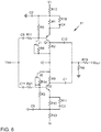
- Fig. 9
- eine Schaltung einer Eingangsstufe
- Fig. 10
- eine Schaltung eines Vorverstärkers und
- Fig. 11
- eine Schaltung einer Endstufe.
- In der
Fig. 1 ist ein Traktionsnetz 1 in einer ersten Ausführungsform dargestellt. Das Traktionsnetz 1 umfasst eine Traktionsbatterie 2 und einen Wechselrichter 3, an den ein Elektromotor 4 angeschlossen ist. Die Traktionsbatterie 2 und der Wechselrichter 3 sind über eine positive Hochvoltleitung HV+ und eine negative Hochvoltleitung HV- miteinander verbunden. Weiter weist das Traktionsnetz 1 einen aktiven Filter 5 auf, der aus einem aktiven HF-Filter 6 und einen aktiven LF-Filter 7 besteht. Zwischen dem aktiven Filter 5 und der Traktionsbatterie 2 ist ein erster passiver Gleichtaktfilter 8 angeordnet. Ein weiterer passiver Gleichtaktfilter 9 ist zwischen dem aktiven Filter 5 und dem Wechselrichter 3 angeordnet. - Eine bevorzugte Ausführungsform des passiven Gleichtaktfilters 8 ist in
Fig. 2 dargestellt. Der passive Gleichtaktfilter 8 weist ein erstes induktives Element L1 und ein zweites induktives Element L2 auf, die beide als Ferritringe ausgebildet sind. Zwischen den beiden induktiven Elementen L1, L2 ist jeweils ein Kondensator CY1, CY2 angeordnet, der zwischen der positiven Hochvoltleitung HV+ bzw. der negativen Hochvoltleitung HV- und Masse angeordnet ist, sodass eine T-Struktur entsteht. - In der
Fig. 3 ist der grundsätzliche Aufbau eines aktiven Filters 5 dargestellt. Der aktive Filter 5 weist eine Eingangsstufe 10, einen Vorverstärker 11 sowie einen Endverstärker 12 bzw. Endstufe auf, wobei die Signale durch Eingangskondensatoren CIN eingekoppelt und durch Ausgangskondensatoren COUT ausgekoppelt wurden. Die Eingangs- und Ausgangskondensatoren CIN, COUT können dabei durch mehrere parallel geschaltete Kondensatoren gebildet werden. - In der
Fig. 4 ist eine mögliche Ausführungsform eines HF-Verstärkers 11 dargestellt. Das Eingangssignal Uin wid durch die beiden Kondensatoren C6, C11 eingekoppelt und durch eine Push-Pull-Stufe aus den beiden komplementären Transistoren Q1, Q2 verstärkt und invertiert. Über die Auskoppelkondensatoren C12, C1 wird dann das Ausgangssignal Uout für den Endverstärker 12 zur Verfügung gestellt. Die beiden Junction-FET J1, J2 bilden zusammen mit den Widerständen R5, R8 bzw. R3, R14 jeweils eine Stromquelle, um temperaturstabilisiert die Arbeitspunkte der Push-Pull-Stufe einzustellen. Über den Widerstand R4 wird ein Floaten des Potentials verhindert. Über die Kondensatoren C2, C9 wird die Versorgungsspannung V+, V-entkoppelt. Gleichzeitig bilden die beiden Kondensatoren C2, C9 eine schnelle Energiequelle für Umladevorgänge in den Transistoren Q1, Q2 der Push-Pull-Stufe. - In der
Fig. 5 ist ein HF-Endverstärker 12 dargestellt. Dabei wird die Ausgangsspannung Uout des Vorverstärkers 11 als Eingangsspannung Uin kapazitiv über die Kondensatoren C14, C15 eingekoppelt und über acht Push-Pull-Stufen verstärkt. Die Emitter-Widerstände der Transistoren der Push-Pull-Stufen (auch jeweils mit Rout gekennzeichnet) dienen zur Stabilisierung, um die Schwingungsneigung zu reduzieren. Die beiden Junction-FETs J3, J4 arbeiten wieder als Stromquelle, um die Arbeitspunkte der Push-Pull-Transistoren temperaturstabilisiert einzustellen. - In der
Fig. 6 ist eine Schaltungsanordnung für einen LF-Vorverstärker 11 dargestellt, der ähnlich dem HF-Verstärker 11 gemäßFig. 4 aufgebaut ist, sodass auf die dortige Beschreibung verwiesen werden kann. - In der
Fig. 7 ist eine LF-Endstufe 12 dargestellt, die weitgehend der Schaltung gemäßFig. 5 entspricht. Wesentlicher Unterschied ist, dass zur Entkopplung der Versorgungsspannung V+, V- nicht jeweils ein Kondensator verwendet wird, sondern ein Kondensatorpaar C14, C16 bzw. C1, C2, wobei die Kondensatoren C14, C16 bzw. C1, C2 eines Kondensatorpaares parallel geschaltet sind. Dabei ist jeweils ein Kondensator eines Kondensatorpaares ein Vielfaches kleiner als der andere Kondensator. Der Faktor liegt beispielsweise zwischen 20 - 30. Insbesondere bei höheren Frequenzen ist der kleine Kondensator aufgrund geringer parasitärer Induktivitäten schneller. Die Größe ist dabei hinsichtlich der Kapazität weniger kritisch, da die Störleistungen im höheren Frequenzbereich kleiner sind. - Der Vorteil eines aktiven HF-Filters 6 und eines aktiven LF-Filters 7 ist, dass die Bauteile an ihre jeweiligen Frequenzbereiche z.B. 0,5 MHz bis 5 MHz für HF und 0,1 MHz bis 0,5 MHz für LF optimal angepasst werden können. Nachteilig ist der erhöhte Bauteileaufwand.
- In der
Fig. 8 ist ein Blockschaltbild eines alternativen Traktionsnetzes 1 mit einem kombinierten HF/LF-Filter 13 dargestellt. - In der
Fig. 9 ist eine Eingangsstufe 10 dargestellt, mittels derer die Spannung heruntertransformiert wird. - In der
Fig. 10 ist ein HF-Vorverstärker 11 des HF/LF-Filters 13 dargestellt, wobei hinsichtlich der Schaltung aufFig. 4 verwiesen werden kann. - Schließlich ist in der
Fig. 11 der LF-Endverstärker 12 dargestellt, wobei auf die Ausführungen zuFig. 7 Bezug genommen wird. Zusätzlich ist ein weiteres Kondensatorpaar C3, C4 vorgesehen, die parallel geschaltet sind und zwischen den Kollektoren der Push-Pull-Stufen eingeordnet sind. Auch hier weist der eine Kondensator eine vielfach höhere Kapazität auf als der andere Kondensator, sodass der kleinere Kondensator für schnelle Umladevorgänge im HF-Bereich zur Verfügung steht. - Der Vorteil eines aktiven kombinierten HF-LF-Filters 13 ist der geringe Bauraum, die Reduzierung der Bauteile sowie der schnelle HF-Vorverstärker. Da in der Eingangsstufe nur die Versorgungsspannung gefiltert wird, kommt es nur zu einem geringen zeitlichen Versatz zwischen Stör- und Kompensationssignal. Die etwas schlechtere Filterwirkung im HF-Bereich kann durch entsprechende Dimensionierung der passiven Gleichtaktfilter 8, 9 kompensiert werden.
Claims (7)
- Traktionsnetz (1) für ein Elektrofahrzeug, umfassend eine Traktionsbatterie (2) undeinen Wechselrichter (3), die über eine positive Hochvoltleitung (HV+) und eine negative Hochvoltleitung (HV-) miteinander verbunden sind, wobei zwischen der positiven Hochvoltleitung (HV+) und der negativen Hochvoltleitung (HV-) mindestens ein aktiver Filter (5) zur Reduktion von Gleichtaktstörimpulsen angeordnet ist, wobei zwischen der Traktionsbatterie (2) und dem aktiven Filter (5) mindestens ein passiver Gleichtaktfilter (8) angeordnet ist, wobeider passive Gleichtaktfilter (8) mehrteilig ausgebildet ist und induktive und kapazitive Elemente aufweist, wobei zwischen zwei als Ferritringe ausgebildeten induktiven Elementen (L1, L2) jeweils ein Kondensator (CY1, CY2) zwischen der positiven Hochvoltleitung (HV+) und der negativen Hochvoltleitung (HV-) und Masse angeordnet ist, wobei die Hochvoltleitungen (HV+, HV-) gemeinsam durch die Ferritringe nur durchgeführt sind.
- Traktionsnetz nach Anspruch 1, dadurch gekennzeichnet, dass der aktive Filter (5) eine Eingangsstufe (10), einen Vorverstärker (11) und einen Endverstärker (12) aufweist.
- Traktionsnetz nach einem der vorangegangenen Ansprüche, dadurch gekennzeichnet, dass der aktive Filter (5) einen aktiven HF-Filter (6) und einen aktiven LF-Filter (7) aufweist.
- Traktionsnetz nach einem der Ansprüche 1 oder 2, dadurch gekennzeichnet, dass der aktive Filter (5) als kombinierter HF/LF-Filter (13) ausgebildet ist.
- Traktionsnetz nach einem der vorangegangenen Ansprüche, dadurch gekennzeichnet, dass zwischen dem aktiven Filter (5) und dem Wechselrichter (3) ein weiterer passiver Filter (9) angeordnet ist.
- Traktionsnetz nach Anspruch 5, dadurch gekennzeichnet, dass der weitere passive Filter (9) als Ferritring ausgebildet ist.
- Traktionsnetz nach Anspruch 6, dadurch gekennzeichnet, dass die Hochvoltleitungen (HV+, HV-) durch den Ferritring nur durchgeführt sind.
Applications Claiming Priority (1)
| Application Number | Priority Date | Filing Date | Title |
|---|---|---|---|
| DE102017223763.5A DE102017223763A1 (de) | 2017-12-22 | 2017-12-22 | Traktionsnetz in einem Elektrofahrzeug |
Publications (2)
| Publication Number | Publication Date |
|---|---|
| EP3501875A1 EP3501875A1 (de) | 2019-06-26 |
| EP3501875B1 true EP3501875B1 (de) | 2022-01-05 |
Family
ID=64665158
Family Applications (1)
| Application Number | Title | Priority Date | Filing Date |
|---|---|---|---|
| EP18212015.4A Active EP3501875B1 (de) | 2017-12-22 | 2018-12-12 | Traktionsnetz in einem elektrofahrzeug |
Country Status (3)
| Country | Link |
|---|---|
| EP (1) | EP3501875B1 (de) |
| CN (1) | CN109962606B (de) |
| DE (1) | DE102017223763A1 (de) |
Families Citing this family (4)
| Publication number | Priority date | Publication date | Assignee | Title |
|---|---|---|---|---|
| CN112721639B (zh) * | 2019-10-28 | 2022-12-13 | 上海度普新能源科技有限公司 | 一种继电器控制方法及装置 |
| DE102021102944A1 (de) | 2021-02-09 | 2022-08-11 | Avl Software And Functions Gmbh | Kühlvorrichtung mit verbessertem EMV-Verhalten |
| DE102023101144A1 (de) | 2023-01-18 | 2024-07-18 | Avl Software And Functions Gmbh | Filter zur Unterdrückung von Gleichtaktstörungen und/oder Gegentaktstörungen |
| DE102023204712A1 (de) * | 2023-05-22 | 2024-11-28 | Robert Bosch Gesellschaft mit beschränkter Haftung | Versorgungschaltungsanordnung für eine elektrische Maschine und System mit der Versorgungschaltungsanordnung |
Family Cites Families (11)
| Publication number | Priority date | Publication date | Assignee | Title |
|---|---|---|---|---|
| US3996537A (en) * | 1975-07-21 | 1976-12-07 | Corcom, Inc. | Noise suppression filter |
| CN2482269Y (zh) * | 2000-12-28 | 2002-03-13 | 深圳市中兴通讯股份有限公司 | 一种开关电源的三相输入滤波装置 |
| CN2476134Y (zh) * | 2000-12-29 | 2002-02-06 | 深圳市中兴通讯股份有限公司 | 一种开关电源的单相输入滤波器 |
| JP2004274161A (ja) * | 2003-03-05 | 2004-09-30 | Tdk Corp | ノイズ抑制回路 |
| JP5315986B2 (ja) * | 2008-12-26 | 2013-10-16 | ヤマハ株式会社 | 電源回路および電源システム |
| CN101651408A (zh) * | 2009-06-10 | 2010-02-17 | 上海爱瑞科技发展有限公司 | 抑制共模杂讯和差模杂讯的滤波模块 |
| DE102009056395A1 (de) * | 2009-11-23 | 2011-05-26 | Esw Gmbh | Verfahren zur Funktionsprüfung von elektrischen Filtern sowie Filter mit Prüfeinrichtung |
| CN203551706U (zh) * | 2013-09-17 | 2014-04-16 | 东莞市杰创电子测控科技有限公司 | 一种无噪音新型寻线仪 |
| DE102014209143A1 (de) * | 2014-05-14 | 2015-11-19 | Volkswagen Aktiengesellschaft | Potentialfreies Gleichspannungsnetz |
| CN104868466B (zh) * | 2015-04-27 | 2017-11-28 | 华为技术有限公司 | 一种滤波装置和电源供电系统 |
| CN105490275A (zh) * | 2016-01-26 | 2016-04-13 | 云南电网有限责任公司电力科学研究院 | 一种并联混合型有源滤波器及其质量检测方法 |
-
2017
- 2017-12-22 DE DE102017223763.5A patent/DE102017223763A1/de not_active Ceased
-
2018
- 2018-12-12 EP EP18212015.4A patent/EP3501875B1/de active Active
- 2018-12-21 CN CN201811570230.6A patent/CN109962606B/zh active Active
Non-Patent Citations (1)
| Title |
|---|
| None * |
Also Published As
| Publication number | Publication date |
|---|---|
| DE102017223763A1 (de) | 2019-06-27 |
| EP3501875A1 (de) | 2019-06-26 |
| CN109962606B (zh) | 2021-12-03 |
| CN109962606A (zh) | 2019-07-02 |
Similar Documents
| Publication | Publication Date | Title |
|---|---|---|
| EP3501875B1 (de) | Traktionsnetz in einem elektrofahrzeug | |
| DE112012005053T9 (de) | Drehmeldererregungsvorrichtung | |
| DE102017105839A1 (de) | Aktives Filter | |
| DE2407376A1 (de) | Kapazitaetsvervielfacherschaltung | |
| DE102011087116A1 (de) | Frequenzvervielfacher | |
| EP3580825B1 (de) | Aktiver filter für bipolare spannungsquellen | |
| EP0195299B1 (de) | Dynamischer Frequenzteiler mit Mischstufe und Verstärker | |
| DE60201778T2 (de) | Spannungskomparatorschaltung | |
| EP4150750A1 (de) | Stromrichter mit gleichtaktfilter | |
| DE3690374C2 (de) | ||
| DE102015205459B4 (de) | Potentialfreies Gleichspannungsnetz | |
| DE112005003419B4 (de) | Aktiver EMC Filter für medizinische Anwendungen | |
| EP2534756B1 (de) | Gegentaktverstärker mit induktiver gleichtaktentkopplung | |
| DE102014209143A1 (de) | Potentialfreies Gleichspannungsnetz | |
| DE102017223764A1 (de) | Aktiver Filter zur Reduktion von Gleichtaktstörimpulsen auf den Hochvoltleitungen | |
| EP2997651B1 (de) | Verfahren und schaltung zur verbesserten nutzung einer kapazität in einem zwischenkreis | |
| WO2023148207A1 (de) | Elektrooptischer mischer | |
| DE2720614C3 (de) | Breitbandverstärker für Fotodioden | |
| DE102011002725A1 (de) | Hochfrequenzoszillator der zweiten Harmonischen | |
| DE102023133260A1 (de) | Elektronische schaltung zur erzeugung eines anregungssignals zur impedanzmessung einer hv-batterie | |
| EP1148549B1 (de) | Integrierte Schaltung mit integrierter HF-Filtereinrichtung | |
| DE102024207166A1 (de) | EMV-Filter und Traktionsnetz | |
| DE102008044845A1 (de) | Bias-Netzwerk | |
| EP3435529B1 (de) | Entstörvorrichtung für einen gleichstromkreis | |
| DE102020133489A1 (de) | Bordnetz für ein Kraftfahrzeug und Kraftfahrzeug |
Legal Events
| Date | Code | Title | Description |
|---|---|---|---|
| PUAI | Public reference made under article 153(3) epc to a published international application that has entered the european phase |
Free format text: ORIGINAL CODE: 0009012 |
|
| STAA | Information on the status of an ep patent application or granted ep patent |
Free format text: STATUS: THE APPLICATION HAS BEEN PUBLISHED |
|
| AK | Designated contracting states |
Kind code of ref document: A1 Designated state(s): AL AT BE BG CH CY CZ DE DK EE ES FI FR GB GR HR HU IE IS IT LI LT LU LV MC MK MT NL NO PL PT RO RS SE SI SK SM TR |
|
| AX | Request for extension of the european patent |
Extension state: BA ME |
|
| STAA | Information on the status of an ep patent application or granted ep patent |
Free format text: STATUS: REQUEST FOR EXAMINATION WAS MADE |
|
| 17P | Request for examination filed |
Effective date: 20191220 |
|
| RBV | Designated contracting states (corrected) |
Designated state(s): AL AT BE BG CH CY CZ DE DK EE ES FI FR GB GR HR HU IE IS IT LI LT LU LV MC MK MT NL NO PL PT RO RS SE SI SK SM TR |
|
| STAA | Information on the status of an ep patent application or granted ep patent |
Free format text: STATUS: EXAMINATION IS IN PROGRESS |
|
| 17Q | First examination report despatched |
Effective date: 20200318 |
|
| RIC1 | Information provided on ipc code assigned before grant |
Ipc: B60L 3/00 20190101AFI20210503BHEP Ipc: H02J 1/02 20060101ALI20210503BHEP Ipc: H02M 1/12 20060101ALI20210503BHEP Ipc: H02M 7/5387 20070101ALI20210503BHEP Ipc: H02M 1/15 20060101ALI20210503BHEP Ipc: H03H 7/42 20060101ALI20210503BHEP Ipc: H02M 1/14 20060101ALI20210503BHEP Ipc: H02J 7/00 20060101ALI20210503BHEP Ipc: H02M 1/44 20070101ALI20210503BHEP |
|
| GRAP | Despatch of communication of intention to grant a patent |
Free format text: ORIGINAL CODE: EPIDOSNIGR1 |
|
| STAA | Information on the status of an ep patent application or granted ep patent |
Free format text: STATUS: GRANT OF PATENT IS INTENDED |
|
| INTG | Intention to grant announced |
Effective date: 20210720 |
|
| GRAS | Grant fee paid |
Free format text: ORIGINAL CODE: EPIDOSNIGR3 |
|
| GRAA | (expected) grant |
Free format text: ORIGINAL CODE: 0009210 |
|
| STAA | Information on the status of an ep patent application or granted ep patent |
Free format text: STATUS: THE PATENT HAS BEEN GRANTED |
|
| AK | Designated contracting states |
Kind code of ref document: B1 Designated state(s): AL AT BE BG CH CY CZ DE DK EE ES FI FR GB GR HR HU IE IS IT LI LT LU LV MC MK MT NL NO PL PT RO RS SE SI SK SM TR |
|
| REG | Reference to a national code |
Ref country code: GB Ref legal event code: FG4D Free format text: NOT ENGLISH |
|
| REG | Reference to a national code |
Ref country code: CH Ref legal event code: EP |
|
| REG | Reference to a national code |
Ref country code: AT Ref legal event code: REF Ref document number: 1460230 Country of ref document: AT Kind code of ref document: T Effective date: 20220115 |
|
| REG | Reference to a national code |
Ref country code: DE Ref legal event code: R096 Ref document number: 502018008407 Country of ref document: DE |
|
| REG | Reference to a national code |
Ref country code: IE Ref legal event code: FG4D Free format text: LANGUAGE OF EP DOCUMENT: GERMAN |
|
| REG | Reference to a national code |
Ref country code: LT Ref legal event code: MG9D |
|
| REG | Reference to a national code |
Ref country code: NL Ref legal event code: MP Effective date: 20220105 |
|
| PG25 | Lapsed in a contracting state [announced via postgrant information from national office to epo] |
Ref country code: NL Free format text: LAPSE BECAUSE OF FAILURE TO SUBMIT A TRANSLATION OF THE DESCRIPTION OR TO PAY THE FEE WITHIN THE PRESCRIBED TIME-LIMIT Effective date: 20220105 |
|
| PG25 | Lapsed in a contracting state [announced via postgrant information from national office to epo] |
Ref country code: SE Free format text: LAPSE BECAUSE OF FAILURE TO SUBMIT A TRANSLATION OF THE DESCRIPTION OR TO PAY THE FEE WITHIN THE PRESCRIBED TIME-LIMIT Effective date: 20220105 Ref country code: RS Free format text: LAPSE BECAUSE OF FAILURE TO SUBMIT A TRANSLATION OF THE DESCRIPTION OR TO PAY THE FEE WITHIN THE PRESCRIBED TIME-LIMIT Effective date: 20220105 Ref country code: PT Free format text: LAPSE BECAUSE OF FAILURE TO SUBMIT A TRANSLATION OF THE DESCRIPTION OR TO PAY THE FEE WITHIN THE PRESCRIBED TIME-LIMIT Effective date: 20220505 Ref country code: NO Free format text: LAPSE BECAUSE OF FAILURE TO SUBMIT A TRANSLATION OF THE DESCRIPTION OR TO PAY THE FEE WITHIN THE PRESCRIBED TIME-LIMIT Effective date: 20220405 Ref country code: LT Free format text: LAPSE BECAUSE OF FAILURE TO SUBMIT A TRANSLATION OF THE DESCRIPTION OR TO PAY THE FEE WITHIN THE PRESCRIBED TIME-LIMIT Effective date: 20220105 Ref country code: HR Free format text: LAPSE BECAUSE OF FAILURE TO SUBMIT A TRANSLATION OF THE DESCRIPTION OR TO PAY THE FEE WITHIN THE PRESCRIBED TIME-LIMIT Effective date: 20220105 Ref country code: ES Free format text: LAPSE BECAUSE OF FAILURE TO SUBMIT A TRANSLATION OF THE DESCRIPTION OR TO PAY THE FEE WITHIN THE PRESCRIBED TIME-LIMIT Effective date: 20220105 Ref country code: BG Free format text: LAPSE BECAUSE OF FAILURE TO SUBMIT A TRANSLATION OF THE DESCRIPTION OR TO PAY THE FEE WITHIN THE PRESCRIBED TIME-LIMIT Effective date: 20220405 |
|
| PG25 | Lapsed in a contracting state [announced via postgrant information from national office to epo] |
Ref country code: PL Free format text: LAPSE BECAUSE OF FAILURE TO SUBMIT A TRANSLATION OF THE DESCRIPTION OR TO PAY THE FEE WITHIN THE PRESCRIBED TIME-LIMIT Effective date: 20220105 Ref country code: LV Free format text: LAPSE BECAUSE OF FAILURE TO SUBMIT A TRANSLATION OF THE DESCRIPTION OR TO PAY THE FEE WITHIN THE PRESCRIBED TIME-LIMIT Effective date: 20220105 Ref country code: GR Free format text: LAPSE BECAUSE OF FAILURE TO SUBMIT A TRANSLATION OF THE DESCRIPTION OR TO PAY THE FEE WITHIN THE PRESCRIBED TIME-LIMIT Effective date: 20220406 Ref country code: FI Free format text: LAPSE BECAUSE OF FAILURE TO SUBMIT A TRANSLATION OF THE DESCRIPTION OR TO PAY THE FEE WITHIN THE PRESCRIBED TIME-LIMIT Effective date: 20220105 |
|
| PG25 | Lapsed in a contracting state [announced via postgrant information from national office to epo] |
Ref country code: IS Free format text: LAPSE BECAUSE OF FAILURE TO SUBMIT A TRANSLATION OF THE DESCRIPTION OR TO PAY THE FEE WITHIN THE PRESCRIBED TIME-LIMIT Effective date: 20220505 |
|
| REG | Reference to a national code |
Ref country code: DE Ref legal event code: R097 Ref document number: 502018008407 Country of ref document: DE |
|
| PG25 | Lapsed in a contracting state [announced via postgrant information from national office to epo] |
Ref country code: SM Free format text: LAPSE BECAUSE OF FAILURE TO SUBMIT A TRANSLATION OF THE DESCRIPTION OR TO PAY THE FEE WITHIN THE PRESCRIBED TIME-LIMIT Effective date: 20220105 Ref country code: SK Free format text: LAPSE BECAUSE OF FAILURE TO SUBMIT A TRANSLATION OF THE DESCRIPTION OR TO PAY THE FEE WITHIN THE PRESCRIBED TIME-LIMIT Effective date: 20220105 Ref country code: RO Free format text: LAPSE BECAUSE OF FAILURE TO SUBMIT A TRANSLATION OF THE DESCRIPTION OR TO PAY THE FEE WITHIN THE PRESCRIBED TIME-LIMIT Effective date: 20220105 Ref country code: EE Free format text: LAPSE BECAUSE OF FAILURE TO SUBMIT A TRANSLATION OF THE DESCRIPTION OR TO PAY THE FEE WITHIN THE PRESCRIBED TIME-LIMIT Effective date: 20220105 Ref country code: DK Free format text: LAPSE BECAUSE OF FAILURE TO SUBMIT A TRANSLATION OF THE DESCRIPTION OR TO PAY THE FEE WITHIN THE PRESCRIBED TIME-LIMIT Effective date: 20220105 Ref country code: CZ Free format text: LAPSE BECAUSE OF FAILURE TO SUBMIT A TRANSLATION OF THE DESCRIPTION OR TO PAY THE FEE WITHIN THE PRESCRIBED TIME-LIMIT Effective date: 20220105 |
|
| PLBE | No opposition filed within time limit |
Free format text: ORIGINAL CODE: 0009261 |
|
| STAA | Information on the status of an ep patent application or granted ep patent |
Free format text: STATUS: NO OPPOSITION FILED WITHIN TIME LIMIT |
|
| PG25 | Lapsed in a contracting state [announced via postgrant information from national office to epo] |
Ref country code: AL Free format text: LAPSE BECAUSE OF FAILURE TO SUBMIT A TRANSLATION OF THE DESCRIPTION OR TO PAY THE FEE WITHIN THE PRESCRIBED TIME-LIMIT Effective date: 20220105 |
|
| 26N | No opposition filed |
Effective date: 20221006 |
|
| PG25 | Lapsed in a contracting state [announced via postgrant information from national office to epo] |
Ref country code: SI Free format text: LAPSE BECAUSE OF FAILURE TO SUBMIT A TRANSLATION OF THE DESCRIPTION OR TO PAY THE FEE WITHIN THE PRESCRIBED TIME-LIMIT Effective date: 20220105 |
|
| P01 | Opt-out of the competence of the unified patent court (upc) registered |
Effective date: 20230526 |
|
| PG25 | Lapsed in a contracting state [announced via postgrant information from national office to epo] |
Ref country code: IT Free format text: LAPSE BECAUSE OF FAILURE TO SUBMIT A TRANSLATION OF THE DESCRIPTION OR TO PAY THE FEE WITHIN THE PRESCRIBED TIME-LIMIT Effective date: 20220105 |
|
| REG | Reference to a national code |
Ref country code: CH Ref legal event code: PL |
|
| REG | Reference to a national code |
Ref country code: BE Ref legal event code: MM Effective date: 20221231 |
|
| PG25 | Lapsed in a contracting state [announced via postgrant information from national office to epo] |
Ref country code: LU Free format text: LAPSE BECAUSE OF NON-PAYMENT OF DUE FEES Effective date: 20221212 |
|
| PG25 | Lapsed in a contracting state [announced via postgrant information from national office to epo] |
Ref country code: LI Free format text: LAPSE BECAUSE OF NON-PAYMENT OF DUE FEES Effective date: 20221231 Ref country code: IE Free format text: LAPSE BECAUSE OF NON-PAYMENT OF DUE FEES Effective date: 20221212 Ref country code: CH Free format text: LAPSE BECAUSE OF NON-PAYMENT OF DUE FEES Effective date: 20221231 |
|
| PG25 | Lapsed in a contracting state [announced via postgrant information from national office to epo] |
Ref country code: BE Free format text: LAPSE BECAUSE OF NON-PAYMENT OF DUE FEES Effective date: 20221231 |
|
| PG25 | Lapsed in a contracting state [announced via postgrant information from national office to epo] |
Ref country code: HU Free format text: LAPSE BECAUSE OF FAILURE TO SUBMIT A TRANSLATION OF THE DESCRIPTION OR TO PAY THE FEE WITHIN THE PRESCRIBED TIME-LIMIT; INVALID AB INITIO Effective date: 20181212 |
|
| PG25 | Lapsed in a contracting state [announced via postgrant information from national office to epo] |
Ref country code: CY Free format text: LAPSE BECAUSE OF FAILURE TO SUBMIT A TRANSLATION OF THE DESCRIPTION OR TO PAY THE FEE WITHIN THE PRESCRIBED TIME-LIMIT Effective date: 20220105 |
|
| PG25 | Lapsed in a contracting state [announced via postgrant information from national office to epo] |
Ref country code: MK Free format text: LAPSE BECAUSE OF FAILURE TO SUBMIT A TRANSLATION OF THE DESCRIPTION OR TO PAY THE FEE WITHIN THE PRESCRIBED TIME-LIMIT Effective date: 20220105 |
|
| PG25 | Lapsed in a contracting state [announced via postgrant information from national office to epo] |
Ref country code: MC Free format text: LAPSE BECAUSE OF FAILURE TO SUBMIT A TRANSLATION OF THE DESCRIPTION OR TO PAY THE FEE WITHIN THE PRESCRIBED TIME-LIMIT Effective date: 20220105 |
|
| PG25 | Lapsed in a contracting state [announced via postgrant information from national office to epo] |
Ref country code: MC Free format text: LAPSE BECAUSE OF FAILURE TO SUBMIT A TRANSLATION OF THE DESCRIPTION OR TO PAY THE FEE WITHIN THE PRESCRIBED TIME-LIMIT Effective date: 20220105 |
|
| PG25 | Lapsed in a contracting state [announced via postgrant information from national office to epo] |
Ref country code: MT Free format text: LAPSE BECAUSE OF FAILURE TO SUBMIT A TRANSLATION OF THE DESCRIPTION OR TO PAY THE FEE WITHIN THE PRESCRIBED TIME-LIMIT Effective date: 20220105 |
|
| REG | Reference to a national code |
Ref country code: AT Ref legal event code: MM01 Ref document number: 1460230 Country of ref document: AT Kind code of ref document: T Effective date: 20231212 |
|
| PG25 | Lapsed in a contracting state [announced via postgrant information from national office to epo] |
Ref country code: AT Free format text: LAPSE BECAUSE OF NON-PAYMENT OF DUE FEES Effective date: 20231212 |
|
| PG25 | Lapsed in a contracting state [announced via postgrant information from national office to epo] |
Ref country code: TR Free format text: LAPSE BECAUSE OF FAILURE TO SUBMIT A TRANSLATION OF THE DESCRIPTION OR TO PAY THE FEE WITHIN THE PRESCRIBED TIME-LIMIT Effective date: 20220105 |
|
| PGFP | Annual fee paid to national office [announced via postgrant information from national office to epo] |
Ref country code: DE Payment date: 20251211 Year of fee payment: 8 |
|
| PGFP | Annual fee paid to national office [announced via postgrant information from national office to epo] |
Ref country code: GB Payment date: 20251219 Year of fee payment: 8 |
|
| PGFP | Annual fee paid to national office [announced via postgrant information from national office to epo] |
Ref country code: FR Payment date: 20251229 Year of fee payment: 8 |
|
| PGFP | Annual fee paid to national office [announced via postgrant information from national office to epo] |
Ref country code: AT Payment date: 20260410 Year of fee payment: 5 |