EP3501859A1 - Transmitter - Google Patents
Transmitter Download PDFInfo
- Publication number
- EP3501859A1 EP3501859A1 EP17912352.6A EP17912352A EP3501859A1 EP 3501859 A1 EP3501859 A1 EP 3501859A1 EP 17912352 A EP17912352 A EP 17912352A EP 3501859 A1 EP3501859 A1 EP 3501859A1
- Authority
- EP
- European Patent Office
- Prior art keywords
- pressure
- tire
- terminal
- box
- deforming portion
- Prior art date
- Legal status (The legal status is an assumption and is not a legal conclusion. Google has not performed a legal analysis and makes no representation as to the accuracy of the status listed.)
- Granted
Links
Images




Classifications
-
- B—PERFORMING OPERATIONS; TRANSPORTING
- B60—VEHICLES IN GENERAL
- B60C—VEHICLE TYRES; TYRE INFLATION; TYRE CHANGING; CONNECTING VALVES TO INFLATABLE ELASTIC BODIES IN GENERAL; DEVICES OR ARRANGEMENTS RELATED TO TYRES
- B60C23/00—Devices for measuring, signalling, controlling, or distributing tyre pressure or temperature, specially adapted for mounting on vehicles; Arrangement of tyre inflating devices on vehicles, e.g. of pumps or of tanks; Tyre cooling arrangements
- B60C23/02—Signalling devices actuated by tyre pressure
- B60C23/04—Signalling devices actuated by tyre pressure mounted on the wheel or tyre
- B60C23/0408—Signalling devices actuated by tyre pressure mounted on the wheel or tyre transmitting the signals by non-mechanical means from the wheel or tyre to a vehicle body mounted receiver
-
- G—PHYSICS
- G01—MEASURING; TESTING
- G01L—MEASURING FORCE, STRESS, TORQUE, WORK, MECHANICAL POWER, MECHANICAL EFFICIENCY, OR FLUID PRESSURE
- G01L13/00—Devices or apparatus for measuring differences of two or more fluid pressure values
- G01L13/02—Devices or apparatus for measuring differences of two or more fluid pressure values using elastically-deformable members or pistons as sensing elements
-
- G—PHYSICS
- G01—MEASURING; TESTING
- G01L—MEASURING FORCE, STRESS, TORQUE, WORK, MECHANICAL POWER, MECHANICAL EFFICIENCY, OR FLUID PRESSURE
- G01L15/00—Devices or apparatus for measuring two or more fluid pressure values simultaneously
-
- G—PHYSICS
- G01—MEASURING; TESTING
- G01L—MEASURING FORCE, STRESS, TORQUE, WORK, MECHANICAL POWER, MECHANICAL EFFICIENCY, OR FLUID PRESSURE
- G01L17/00—Devices or apparatus for measuring tyre pressure or the pressure in other inflated bodies
-
- G—PHYSICS
- G01—MEASURING; TESTING
- G01L—MEASURING FORCE, STRESS, TORQUE, WORK, MECHANICAL POWER, MECHANICAL EFFICIENCY, OR FLUID PRESSURE
- G01L19/00—Details of, or accessories for, apparatus for measuring steady or quasi-steady pressure of a fluent medium insofar as such details or accessories are not special to particular types of pressure gauges
- G01L19/0092—Pressure sensor associated with other sensors, e.g. for measuring acceleration or temperature
Definitions
- the present invention relates to a transmitter adapted to be attached to each one of the wheel assemblies of a vehicle.
- Patent Document 1 describes a transmitter adapted to be arranged in a vehicle having wheel assemblies.
- a tire pressure monitoring device described in this publication includes transmitters and a receiver. Each of the transmitters is mounted in one of the wheel assemblies.
- Each transmitter includes a pressure sensor, a controller, and a transmitting section.
- the pressure sensor detects the pressure in the tire (the tire internal pressure).
- the controller intermittently obtains data of the tire pressure detected by the pressure sensor.
- the transmitting section transmits a data signal carrying the pressure data to the receiver.
- the receiver receives data signals from the transmitters arranged in the respective wheel assemblies and thus obtains the fact that the pressure in the tire has abruptly dropped or is excessively low.
- Patent Document 1 Japanese Laid-Open Patent Publication No. 2014-91344
- each period between obtainment of pressure data and subsequent obtainment of pressure data elapses without obtainment of pressure data. That is, there are periods in which the receiver cannot obtain the tire pressures. If, in one of such periods, a sudden pressure drop occurs in any one of the tires, the receiver cannot obtain this sudden pressure drop until the pressure data is obtained.
- a transmitter adapted to be arranged in a tire to cause a tire pressure warning device to issue a warning.
- the transmitter includes a transmitting section, which has a terminal, and a pressure switch.
- the pressure switch includes a hollow box and a passage that causes an interior of the box and an interior of the tire to communicate with each other.
- the box includes a conductive deforming portion, which is configured to be separate from the terminal of the transmitting section when a difference between a pressure in the box and a pressure in the tire is less than a predetermined value and to be elastically deformed to contact the terminal when the pressure in the box is higher than the pressure in the tire at least by the predetermined value.
- the transmitting section is configured to transmit a warning signal that causes the tire pressure warning device to issue a warning in response to contact between the deforming portion and the terminal.
- the pressure in the box drops in correspondence with the pressure in the tire.
- the passage functions as an orifice to limit gas discharge from the box through the passage.
- the pressure in the box thus drops more slowly than the pressure in the tire.
- the pressure in the box becomes temporarily higher than the pressure in the tire.
- the deforming portion elastically deforms and comes into contact with the terminal.
- the deforming portion elastically restores its original shape and thus separates from the terminal.
- Such transmission of the warning signal in response to elastic deformation of the deforming portion causes the warning device to issue a warning immediately after the sudden pressure drop in the tire.
- the above transmitter may include a flow rate reducing portion, which is configured to, in a state in which the pressure in the tire is lower than the pressure in the box, cause a flow rate of gas discharged from the box through the passage to be smaller when the deforming portion and the terminal are in contact with each other than when the deforming portion and the terminal are separate from each other.
- the passage is provided in the deforming portion, and the terminal is configured to limit the flow rate of the gas discharged from the box through the passage when the terminal contacts the deforming portion.
- the above transmitter may include a flow rate increasing portion, which is configured to, in a state in which the pressure in the tire is lower than the pressure in the box, cause a flow rate of gas discharged from the box through the passage to be smaller when the deforming portion and the terminal are separate from each other than when the deforming portion and the terminal are in contact with each other.
- the deforming portion in correspondence with the difference between the pressure in the tire and the pressure in the box, the deforming portion repeatedly comes into contact with and separates from the terminal. Such contact and separation of the deforming portion with respect to the terminal occur at an interval that becomes shorter as the dropping amount of the pressure in the tire per unit time becomes greater.
- the warning signal is transmitted each time the deforming portion comes into contact with the terminal. With reference to the interval at which the tire pressure warning device receives the warning signal, the tire pressure warning device obtains the degree of the problem that has occurred in the tire.
- the present invention enables the warning device to issue a warning immediately after a sudden pressure change in the tire.
- a transmitter according to one embodiment will now be described.
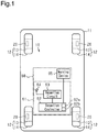
- a tire pressure monitoring device 10 includes transmitters 20 and a tire pressure warning device 60.
- Each of the transmitters 20 is attached to one of four wheel assemblies 12 of a vehicle 11.
- the tire pressure warning device 60 is arranged in the body of the vehicle 11.
- Each of the wheel assemblies 12 includes a wheel 13 and a tire 14.
- the tire 14 is mounted on the wheel 13.
- the tire pressure warning device 60 includes a receiver 61 and a warning device 65.
- each of the transmitters 20 is integrated with a tire valve 16 mounted on a rim 15 of one of the wheels 13. To arrange the transmitter 20 in the internal space of the tire 14, the transmitter 20 is attached to the wheel 13, on which the tire 14 is mounted.
- Each transmitter 20 includes a normal-time transmission device 20A and a sudden-pressure-change transmission device 20B.
- the normal-time transmission device 20A and the sudden-pressure-change transmission device 20B are integrated with each other.
- the normal-time transmission devices 20A includes a pressure sensor 21, a temperature sensor 22, a controller 24, a normal-time transmission circuit 25, an antenna 27, and a battery 26.
- the normal-time transmission device 20A operates using the battery 26.
- the controller 24 controls the operation of the normal-time transmission device 20A in an integrated manner.
- the pressure sensor 21 detects the pressure in the corresponding tire 14 (the tire internal pressure) and outputs the pressure data of the tire 14 obtained through such detection to the controller 24.
- the temperature sensor 22 detects the temperature in the corresponding tire 14 (the tire internal temperature) and outputs the temperature data of the tire 14 obtained through such detection to the controller 24.
- the controller 24 is constituted by a microcomputer including a CPU 24a, a memory section 24b (such as a RAM or a ROM), and a timer.
- the memory section 24b registers ID codes that carry ID information specific to the respective normal-time transmission devices 20A.
- the ID codes represent information used to enable the receiver 61 to identify each of the normal-time transmission devices 20A.
- the controller 24 generates pressure data, temperature data, and data including the ID code and outputs the data to the normal-time transmission circuit 25.
- the normal-time transmission circuit 25 modulates the data provided by the controller 24 to generate a data signal (an RF signal) and wirelessly transmits the data signal through the antenna 27.
- the data signal is transmitted as a signal of an RF band (such as the 315 MHz band or 434 MHz band).
- the controller 24 may include dedicated hardware (an application specific integrated circuit: ASIC) that executes at least part of the various processes. That is, the controller 24 may be circuitry including 1) one or more processors that operate according to a computer program (software), 2) one or more dedicated hardware circuits such as an ASIC, or 3) a combination thereof.
- the processor includes a CPU and memories such as a RAM and ROM.
- the memories store program codes or instructions configured to cause the CPU to execute processes.
- the memories, or computer readable media include any type of media that are accessible by general-purpose computers and dedicated computers.
- the controller 24 obtains the data of the pressure detected by the pressure sensor 21 intermittently at predetermined obtainment intervals t11.
- the obtainment interval t11 is, for example, from ten seconds to several tens of seconds.
- the controller 24 performs normal-time transmission, in which the data signal is transmitted at predetermined intervals. If the pressure the corresponding tire 14 abruptly drops or is excessively low, the controller 24 determines that a problem has occurred in the tire 14 and transmits a pressure drop signal.
- the pressure drop signal may be a signal similar to the data signal or a signal of any format such as a signal carrying a warning flag.
- each of the sudden-pressure-change transmission devices 20B includes a battery 30, a transmission circuit 34, a pressure switch 40, a conductive member 50 made of metal, and a case 51.
- the case 51 accommodates the listed components.
- the transmission circuit 34, the battery 30, and the pressure switch 40 are stacked together.
- the battery 30 is shaped like a disk.
- the battery 30 serves as the electric power supply for the transmission circuit 34.
- the transmission circuit 34 transmits a predetermined warning signal.
- the warning signal must at least be a signal carrying an ID code.
- the transmission circuit 34 continuously transmits the warning signal as long as the transmission circuit 34 is supplied with electric power from the battery 30.
- the ID code carried by the warning signal may be an ID code that is either identical with or different from the ID code of the normal-time transmission device 20A integrated with the sudden-pressure-change transmission device 20B.
- the transmission circuit 34 includes two terminals 35, 36. In the present embodiment, the terminals 35, 36 are electric-power supplying terminals.
- the pressure switch 40 includes a box 41 made of metal.
- the box 41 is hollow and includes a cylindrical peripheral wall 42, a wall section 44, and a deforming portion 45.
- the wall section 44 is arranged on one of the opposite ends (the opposite axial ends) of the peripheral wall 42.
- the deforming portion 45 is arranged on the other one of the opposite ends of the peripheral wall 42.
- the wall section 44 has a circular and flat plate-like shape.
- the deforming portion 45 is arranged to dent in the axial direction of the peripheral wall 42 from a peripheral edge 43 of the peripheral wall 42.
- the deforming portion 45 includes a circular contact portion 46 and a retractable portion 47.
- the retractable portion 47 connects the peripheral edge of the contact portion 46 to the peripheral edge 43 of the peripheral wall 42.
- the dimension L1 from the contact portion 46 to the wall section 44 in the axial direction of the peripheral wall 42 is smaller than the dimension L2 from the peripheral edge 43 to the wall section 44 in the axial direction of the peripheral wall 42. That is, the deforming portion 45 is located on the inner side of the peripheral wall 42.
- the pressure switch 40 includes multiple passages 48.
- the multiple passages 48 allow the interior and the exterior of the box 41 to communicate with each other and extend through the contact portion 46.
- the transmission circuit 34 serving as a transmitting section and an end face 31 of the battery 30 face each other.
- the terminal 35 is joined to the end face 31 of the battery 30.
- the conductive member 50 is arranged between the battery 30 and the pressure switch 40. The conductive member 50 is joined to the end face 32 of the battery 30 and the wall section 44 of the pressure switch 40.
- the terminal 36 has a section that faces the deforming portion 45 of the pressure switch 40.
- the terminal 36 includes a first section 37 and a second section 38.
- the first section 37 extends along the battery 30 and the pressure switch 40 from the transmission circuit 34.
- the second section 38 extends from the first section 37 to a position facing the contact portion 46.
- the second section 38 is arranged in a separate state from the contact portion 46 of the pressure switch 40.
- the second section 38 faces the section of the contact portion 46 in which the passages 48 are arranged.
- the second section 38 faces openings 49 of the passages 48.
- the openings 49 are located on the outer side of the box 41.
- the case 51 is made of an insulating material such as plastic.
- the case 51 includes a battery holding portion 52 and a switch holding portion 53.
- the battery holding portion 52 holds the battery 30, and the switch holding portion 53 holds the pressure switch 40.
- the battery holding portion 52 is arranged not to hamper expansion and contraction of the battery 30 at the time the battery 30 is used.
- the expansion and contraction of the battery 30 is absorbed through elastic deformation of the conductive member 50. This restricts displacement of the pressure switch 40 caused by the expansion and contraction of the battery 30.
- the case 51 has a hole that allows the interior and the exterior of the case 51 to communicate with each other.
- the pressure in the case 51 is assumed to be always equal to the pressure in the tire 14 in the following description.
- the passages 48 allow the interior and the exterior of the box 41 to communicate with each other.
- the pressure in the box 41 varies in correspondence with pressure variation in the tire 14. If the pressure variation in the tire 14 is small, the pressure in the tire 14 is assumed to be equal to the pressure in the box 41.
- the deforming portion 45 is located on the inner side of the peripheral wall 42 and the contact portion 46 and the terminal 36 are maintained in the separate state.
- the deforming portion 45 of the pressure switch 40 is elastically deformed by the pressure difference between the interior and the exterior of the box 41.
- the retractable portion 47 of the deforming portion 45 is elastically deformed when the pressure in the box 41 is higher than the pressure in the exterior of the box 41 (the pressure in the tire 14) at least by the amount corresponding to a predetermined value.
- the deforming portion 45 elastically deforms to project outward with respect to the peripheral edge 43 of the peripheral wall 42 in the axial direction of the peripheral wall 42.
- Such elastic deformation of the deforming portion 45 causes the dimension L1 to be longer than the dimension L2.
- the contact portion 46 and the terminal 36 come into contact with each other through elastic deformation of the deforming portion 45.
- the transmission circuit 34 is thus supplied with electric power and transmits the warning signal.
- the aforementioned "predetermined value” can be set to any value in such a range in which deformation of the deforming portion 45 of the pressure switch 40 is ensured at the time of a sudden pressure change.
- the sudden pressure change represents a pressure drop exceeding a pressure variation amount (per unit time) at the time of natural pressure drop caused by traveling of the vehicle.
- the sudden pressure change occurs when, for example, the tire 14 bursts.
- each of the passages 48 functions as an orifice such that the pressure in the box 41 drops more slowly than the pressure in the tire 14.
- a pressure difference is brought about between the pressure in the tire 14 and the pressure in the box 41.
- the pressure difference causes elastic deformation of the deforming portion 45.
- the pressure difference between the interior of the tire 14 and the interior of the box 41 caused by bursting of the tire 14 under recommended pressure is estimated.
- the "predetermined value" is set such that the deforming portion 45 is elastically deformed by a pressure difference smaller than the estimated pressure difference.
- the pressure difference between the interior and the exterior of the box 41 necessary for elastically deforming the deforming portion 45 changes depending on the shape of the deforming portion 45, the material of the deforming portion 45, the dimensions of the deforming portion 45, the cross-sectional flow area of the passages 48, and the volume of the box 41.
- the deforming portion 45 is provided such that "predetermined value" is satisfied. This enables elastic deformation of the deforming portion 45 when the pressure in the box 41 is higher than the pressure in the tire 14 at least by the amount corresponding to the predetermined value.
- the deforming portion 45 is configured to be elastically deformed when the pressure in the box 41 is higher than the pressure in the tire 14 at least by the amount corresponding to the predetermined value.
- tolerance may cause a slight error in the pressure difference necessary for elastic deformation of the deforming portion 45.
- the "predetermined value" tolerates such slight errors caused by tolerance.
- the deforming portion 45 When the deforming portion 45 is elastically deformed by the pressure difference between the interior and the exterior of the box 41, the openings 49 of the passages 48 are blocked by the terminal 36. The gas in the box 41 is discharged through the gap between the openings 49 and the terminal 36. By discharging the gas from the box 41 through the passages 48, the pressure in the box 41 drops slowly.
- the opening area of each opening 49 becomes smaller than that when the openings 49 of the passages 48 are not blocked by the terminal 36. This limits the flow rate of the gas discharged through the passages 48.
- the flow rate of the gas discharged from the box 41 through the passages 48 is smaller when the deforming portion 45 and the terminal 36 are in contact with each other than when the deforming portion 45 and the terminal 36 are separate from each other.
- the terminal 36 functions as a flow rate reducing portion.
- the gap between the openings 49 and the terminal 36 and the passages 48 are collectively regarded as a passage that allows the interior of the box 41 and the interior of the tire 14 to communicate with each other, the cross-sectional flow area of this passage is reduced by the flow rate reducing portion through contact between the deforming portion 45 and the terminal 36.
- the elastic force of the deforming portion 45 restores the original shape of the deforming portion 45.
- the deforming portion 45 and the terminal 36 thus separate from each other, thus ending electric power supply to the transmission circuit 34. That is, when a sudden pressure change occurs in the tire 14, the transmission circuit 34 is temporarily supplied with electric power.
- the time for which elastic deformation of the deforming portion 45 is maintained may be adjusted as needed by changing the shape of the deforming portion 45, the material of the deforming portion 45, the dimensions of the deforming portion 45, or the flow rate of the gas discharged through the passages 48.
- the flow rate of the gas discharged through the passages 48 may be adjusted by changing the cross-sectional flow area of the passages 48 and the opening area of each opening 49.
- the shape of the deforming portion 45 is set to maintain elastic deformation of the deforming portion 45 for the time corresponding to the obtainment interval t11 or longer when the tire 14 bursts with the pressure in the tire 14 maintained at the recommended pressure.
- the cross-sectional flow area refers to the sum of the cross-sectional flow areas of the passages 48.
- the pressure switch 40 is turned on and off depending on the pressure difference. In this manner, the pressure switch 40 functions as a mechanical switch that switches between supplying electric power to the transmission circuit 34 and blocking such supply of the electric power.
- the receiver 61 includes a reception controller 62, a reception circuit 63, and a reception antenna 64.
- the reception controller 62 of the receiver 61 is connected to a warning device 65.
- the reception controller 62 is constituted by a microcomputer including a CPU 62a and a reception-side memory section 62b (a ROM or a RAM) and controls the operation of the receiver 61 in an integrated manner.
- the reception-side memory section 62b memorizes the ID codes of the transmitters 20. If the normal-time transmission devices 20A use ID codes different from those of the corresponding sudden-pressure-change transmission devices 20B, the respective ID codes are memorized.
- the reception circuit 63 receives the data signals, the pressure drop signals, and the warning signals that are transmitted by the transmitters 20 through the reception antenna 64.
- the reception circuit 63 demodulates the data signals, the pressure drop signals, and the warning signals and outputs the signals to the reception controller 62.
- the reception controller 62 Based on the data signals, the reception controller 62 obtains the states of the tires 14, such as the pressure in the tire 14 and the temperature in the tire 14. The reception controller 62 also determines whether a problem has occurred in the tire 14 based on the pressure drop signal and warning signal. If the tire 14 has a problem, the reception controller 62 issues a warning by means of the warning device 65.
- the warning device 65 may be either a type that issues a warning using sound and vibration, illumination, or a display device that displays the fact that a problem has occurred in the tire 14.
- the controller 24 obtains the pressure data at a point in time T0 and then at a point in time T2 in the subsequent cycle.
- the point in time T1 is between the point in time T0 and the point in time T2.
- the controller 24 detects the sudden pressure change when obtaining the pressure data at the point in time T2, later than the point in time T1. In response to such detection, the controller 24 transmits the pressure drop signal. Despite the sudden pressure change, the period from the point in time T1 to the point in time T2 elapses without transmission of the pressure drop signal,.
- the deforming portion 45 of the pressure switch 40 comes into contact with the terminal 36. This causes the transmission circuit 34 to transmit the warning signal. Since the time necessary for elastic deformation of the deforming portion 45 is short, the warning signal is transmitted immediately after the sudden pressure change. In other words, the warning signal is transmitted sooner than the pressure drop signal.
- the normal-time transmission device 20A intermittently obtains the pressure data. Therefore, even when a sudden pressure change occurs, the normal-time transmission device 20A cannot detect the sudden pressure change unless the pressure data is obtained. This may delay detection of the sudden pressure change. Specifically, there may be cases in which, after the occurrence of a sudden pressure change, the controller 24 consumes time substantially equal to the obtainment interval t11 before detection of the sudden pressure change.
- the sudden-pressure-change transmission device 20B elastically deforms the deforming portion 45 in response to the pressure difference greater than or equal to the predetermined value.
- the deforming portion 45 thus comes into contact with the terminal 36 and transmits the warning signal.
- the pressure difference mechanically turns on the switch connecting the transmission circuit 34 to the battery 30 such that the warning signal is transmitted.
- the warning signal is transmitted immediately after the sudden pressure change.
- the sudden-pressure-change transmission device 20B stops transmitting the warning signal. Since elastic deformation of the deforming portion 45 is maintained for the time corresponding to the obtainment interval t11 or longer, the normal-time transmission device 20A will have transmitted the pressure drop signal by the point in time at which transmission of the warning signal ends. Therefore, even without transmitting the warning signal, the receiver 61 continuously obtains the fact that a problem has occurred in the tire 14.
- a pressure switch that has the box 41 of the present embodiment but without the passages 48 may be used as a pressure switch 200.
- the deforming portion 45 of the pressure switch 200 projects on the outer side of the peripheral wall 42 and is thus in contact with the terminal 36.
- the pressure switch 200 is arranged in the tire 14, the pressure in the exterior of the box 41 is higher than the pressure in the box 41.
- the deforming portion 45 thus separates from the terminal 36.
- the deforming portion 45 of the pressure switch 200 is deformed by the pressure (the absolute pressure) in the exterior of the box 41.
- the deforming portion 45 comes into contact with the terminal 36 such that the warning signal is transmitted.
- a sudden-pressure-change transmission device using the pressure switch 200 is first manufactured.
- the deforming portion 45 and the terminal 36 are in contact with each other until the sudden-pressure-change transmission device is mounted in the wheel assembly 12. Therefore, the warning signal is continuously transmitted until the sudden-pressure-change transmission device is mounted in the wheel assembly 12, thus increasing consumption of the electric power of the battery 30.
- Contact between the deforming portion 45 and the terminal 36 may be prevented by maintaining an insulating material between the deforming portion 45 and the terminal 36 until the sudden-pressure-change transmission device is mounted in the wheel assembly 12.
- attachment and detachment of the insulating material is troublesome.
- locking may be performed to suspend transmission of the warning signal until the sudden-pressure-change transmission device is attached to the wheel assembly 12. Such locking is canceled after the sudden-pressure-change transmission device is mounted in the wheel assembly 12.
- a trigger device or the like must be used to selectively cause and cancel such locking, which is also troublesome.
- the sudden-pressure-change transmission device 20B of the present embodiment elastically deforms the deforming portion 45 in response to the pressure difference between the interior and the exterior of the box 41. Therefore, contact between the deforming portion 45 and the terminal 36 is considered unlikely in the period from when the sudden-pressure-change transmission device 20B is manufactured to when the sudden-pressure-change transmission device 20B is mounted in the wheel assembly 12. Even if the deforming portion 45 is elastically deformed and comes into contact with the terminal 36 before the sudden-pressure-change transmission device 20B is mounted in the wheel assembly 12, the deforming portion 45 elastically restores its original shape. This restrains continuous transmission of the warning signal for a prolonged period.
- the above-described embodiment has the sudden-pressure-change transmission device 20B dedicated to transmit the warning signal at the time of a sudden pressure change.
- the normal-time transmission device 20A may have a function of transmitting the warning signal.
- the transmitter 20 thus lacks the sudden-pressure-change transmission device 20B and includes only the normal-time transmission device 20A.
- the controller 24 and the normal-time transmission circuit 25 of the normal-time transmission device 20A serve as a transmitting section.
- the transmitting section is a component necessary for transmitting the warning signal. If, as described above regarding the above-described embodiment, transmission of the warning signal is accomplished only by the transmission circuit 34, the transmission circuit 34 serves as the transmitting section. If, as shown in Fig. 10 , the data generated by the controller 24 is transmitted from the normal-time transmission circuit 25, the controller 24 and the normal-time transmission circuit 25 serve as the transmitting section.
- a terminal 81 of a transmitting section 82 is an interrupt terminal.
- the deforming portion 45 comes into contact with the terminal 81 when the pressure in the box 41 becomes higher than the pressure in the tire 14 at least by the amount corresponding to the predetermined value.
- Such contact between the deforming portion 45 and the terminal 81 changes the voltage level, thus causing the controller 24 to perform an interrupt procedure.
- the interrupt procedure may be a procedure of transmitting a warning signal from the normal-time transmission device 20A.
- the interrupt procedure may be a procedure of obtaining the pressure data from the pressure sensor 21. After the pressure data is obtained from the pressure sensor 21, the transmitting section 82 transmits a pressure drop signal as the warning signal. In either case, when a sudden pressure change occurs, the tire pressure warning device 60 is caused to issue a warning in response to contact between the deforming portion 45 and the terminal 81.
- a common transmission circuit can be employed as the transmission circuit for transmitting the warning signal and the transmission circuit for transmitting the data signal (the normal-time transmission circuit 25).
- a common battery can be employed as the electric power supply for these transmission circuits.
- the transmitter 20 is thus reduced in size compared to the case in which the transmitter 20 includes both the normal-time transmission device 20A and the sudden-pressure-change transmission device 20B. In addition, this configuration facilitates checking of the operation of the transmitter 20 using a trigger device or the like.
- the pressure switch 40 may include an accommodated body 70 accommodated in the box 41.
- the accommodated body 70 functions as a flow rate limiting portion and includes a contacting portion 71 and a side wall 72.
- the contacting portion 71 comes into contact with the contact portion 46.
- the side wall 72 extends from the contacting portion 71 to the wall section 44.
- the accommodated body 70 includes a communication passage 73 and a through-hole 74.
- the communication passage 73 extends through the contacting portion 71.
- the through-hole 74 extends through the side wall 72.
- the communication passage 73 has a cross-sectional flow area smaller than that of a passage 75 arranged in the contact portion 46.
- the terminal 36 has a terminal passage 76 facing the passage 75.
- the cross-sectional flow area of the terminal passage 76 is greater than the cross-sectional flow area of the communication passage 73.
- Elastic deformation of the deforming portion 45 causes communication between the passage 75 and the terminal passage 76.
- the gas discharged through the communication passage 73 is discharged through the passage 75. If the deforming portion 45 and the contacting portion 71 are in contact with each other, the flow rate of the gas discharged from the box 41 through the passage 75 depends on the cross-sectional flow area of the communication passage 73.
- the passage 75 and the terminal passage 76 communicate with each other.
- the flow rate of the gas discharged through the passage 75 depends on the cross-sectional flow area of the terminal passage 76.
- the cross-sectional flow area of the terminal passage 76 is greater than the cross-sectional flow area of the communication passage 73.
- the flow rate of the gas discharged through the passage 75 is thus smaller when the deforming portion 45 and the terminal 36 are separate from each other than when the deforming portion 45 and the terminal 36 are in contact with each other.
- the accommodated body 70 and the terminal passage 76 function as a flow rate increasing portion.
- a sudden pressure drop causes contact between the deforming portion 45 and the terminal 36.
- Such contact between the deforming portion 45 and the terminal 36 causes the flow rate of discharged gas to be smaller than that when the deforming portion 45 is in contact with the contacting portion 71.
- Such shape restoration of the deforming portion 45 causes contact between the deforming portion 45 and the contacting portion 71, thus reducing the flow rate of the gas discharged from the box 41.
- This promotes increase of the difference between the pressure in the tire 14 and the pressure in the box 41, thus elastically redeforming the deforming portion 45.
- the deforming portion 45 repeatedly comes into contact with and separates from the terminal 36 in an alternating manner.
- Such contact and separation are alternately repeated at an interval that becomes shorter as the dropping amount of pressure per unit time becomes greater.
- the warning signal is transmitted each time the deforming portion 45 comes into contact with the terminal 36. That is, the interval at which the deforming portion 45 comes into contact with the terminal 36 and the interval at which the warning signal is transmitted are synchronous.
- the reception controller 62 By receiving the warning signal, the reception controller 62 is enabled to issue a warning. Also, with reference to the interval at which the reception controller 62 receives the warning signal, the reception controller 62 obtains the degree of the problem that has occurred in the tire 14. The shorter the interval of warning signal reception, the more sudden pressure drop in the tire 14 becomes. Also, the interval of warning signal reception is used by the reception controller 62 to calculate the dropping amount (the drop rate) of pressure per unit time.
- the locations of the transmission circuit 34, the battery 30, and the pressure switch 40 may be changed as needed.
- the peripheral wall 42 and a side surface of the battery 30 may face each other, and another side surface of the battery 30 and the transmission circuit 34 may face each other.
- the terminal 36 may include a tubular portion 84 projecting from the second section 38 toward the contact portion 46.
- the tubular portion 84 extends from the terminal 36 toward the contact portion 46.
- a terminal passage 85 is arranged in a section of the tubular portion 84 to cause the interior and the exterior of the tubular portion 84 to communicate with each other.
- the cross-sectional flow area of the terminal passage 85 is smaller than the cross-sectional flow area of each passage 48.
- the deforming portion 45 elastically deforms and comes into contact with the tubular portion 84.
- the passages 48 communicate with the range surrounded by the tubular portion 84 and the contact portion 46.
- the range and the interior of the tire 14 communicate with each other through the terminal passage 85. Since the cross-sectional flow area of the terminal passage 85 is smaller than the cross-sectional flow area of each passage 48, the flow rate of the gas discharged through the passages 48 is small when the deforming portion 45 and the contact portion 46 are in contact with each other.
- the tubular portion 84 and the terminal passage 85 function as a flow rate reducing portion.
- the terminal 36 may include a terminal passage 88 having a cross-sectional flow area smaller than the cross-sectional flow area of a passage 87 arranged in the contact portion 46.
- the terminal passage 88 is located at such a position where, when the deforming portion 45 and the terminal 36 come into contact with each other, the terminal passage 88 communicates with the passage 87.
- the terminal passage 88 functions as a flow rate reducing portion to reduce the flow rate of the gas discharged through the passage 87 when the deforming portion 45 and the terminal 36 are in contact with each other.
- the terminal 36 may have a terminal passage 91.
- the terminal passage 91 When the deforming portion 45 and the terminal 36 come into contact with each other, the terminal passage 91 becomes overlapped with a section of a passage 90 arranged in the contact portion 46.
- the terminal passage 91 has a cross-sectional flow area not less than the cross-sectional flow area of the passage 90.
- the area by which the terminal passage 91 and the passage 90 are overlapped with each other when the deforming portion 45 is in contact with the terminal 36 is less than the cross-sectional flow area of the passage 90. Therefore, the terminal passage 91 functions as a flow rate reducing portion to reduce the flow rate of the gas discharged through the passage 90 when the deforming portion 45 and the contact portion 46 are in contact with each other.
- the terminal 36 may include a terminal passage 93.
- the terminal passage 93 communicates with some of the passages 48 arranged in the contact portion 46.
- the terminal passage 93 functions as a flow rate reducing portion to reduce the flow rate of the gas discharged through the passages 48 when the deforming portion 45 and the contact portion 46 are in contact with each other.
- the passages 48 may be arranged in the wall section 44. Alternatively, the passages 48 may be arranged in either the peripheral wall 42 or the retractable portion 47.
- a passage 96 of the pressure switch 40 may have an air-permeable filter 97. Since the filter 97 causes pressure loss, the air permeability of the filter 97 is taken into consideration when setting the cross-sectional flow area of the passage 96.
- the transmitter 20 may be attached to the wheel assembly in any manners.
- the transmitter 20 may be bonded to the tire 14.
- the transmitter 20 may be configured to include the sudden-pressure-change transmission device 20B but not the normal-time transmission device 20A. Even in this case, when a sudden pressure change occurs in the tire 14, the warning signal transmitted by the sudden-pressure-change transmission device 20B causes the warning device 65 to issue a warning. Further, since the sudden-pressure-change transmission device 20B transmits the warning signal temporarily at the time of a sudden pressure change, the sudden-pressure-change transmission device 20B transmits signals less frequently than the normal-time transmission device 20A. Therefore, the sudden-pressure-change transmission device 20B consumes less electric power than the normal-time transmission device 20A. This prolongs the life of the transmitter 20 if a battery with the capacity equal to that of the battery 26 of the normal-time transmission device 20A is used as the battery 30 of the sudden-pressure-change transmission device 20B.
- the sudden-pressure-change transmission device 20B has a smaller number of components than the normal-time transmission device 20A. This reduces the cost for manufacturing the transmitter 20.
- the box 41 may have any shape as long as the box 41 has a deforming portion and the deforming portion is deformable by the pressure difference between the interior and the exterior of the box 41.
- the peripheral wall 42 may have a rectangular tubular shape.
- the deforming portion does not necessarily have to be made of metal as long as the deforming portion is conductive and elastically deformable.
- the deforming portion may be made of elastically deformable conductive plastic or made of an elastically deformable plastic material having a metal-plated or conductive-coated surface or an elastically deformable plastic material having a metal mesh attached thereto.
- the deforming portion does not necessarily have to be conductive as a whole, if it is conductive at least in the section that contacts the terminal 36.
- the listed deforming portions are light-weighted and enable shape setting with improved flexibility. Further, these deforming portions are easier to machine than a deforming portion made of metal.
- the passages 48 may be replaced by a single passage 48.
- the wall section 44 of the pressure switch 40 and the end face 32 of the battery 30 may be in direct contact with each other.
- the conductive member 50 is not employed.
- the peripheral wall 42 and the wall section 44 of the pressure switch 40 may be made of any material other than metal, such as plastic. That is, at least the deforming portion 45 of the pressure switch 40 must be made of metal.
- the normal-time transmission device 20A and the sudden-pressure-change transmission device 20B do not necessarily have to be integrated with each other but may be attached to the wheel assembly 12 independently from each other as shown in Fig. 16 .
- the normal-time transmission device 20A and the sudden-pressure-change transmission device 20B may each be attached to the wheel assembly 12 by being integrated with the tire valve 16 or being bonded to the inner side of the wheel 13 or the inner side of the tire 14. That is, the normal-time transmission device 20A and the sudden-pressure-change transmission device 20B may be attached at any site as long as the transmission devices 20A, 20B are arranged in the tire 14 and capable of detecting the pressure in the tire 14. Specifically, by attaching the normal-time transmission device 20A and the sudden-pressure-change transmission device 20B at opposite positions with respect to the rotation axis of the wheel 13, a light-weighted balance weight can be employed for balance adjustment of the tire 14.
- the tire pressure warning device may be any device as long as the device has a function of receiving a warning signal and a function of issuing a warning, such as a portable terminal carried by an occupant of the vehicle.
- the vehicle may be a motorcycle or a vehicle having five or more wheel assemblies.
- Signals of the 2.4 GHz band may be used as the data signal, the pressure drop signal, and the warning signal.
- the data signal does not necessarily have to carry the temperature data.
- the normal-time transmission device 20A may lack the temperature sensor 22.
- the transmitter 20 may transmit the data signal at a constant position (for example, the lowermost position). Based on the correlative relationship between the timing at which the reception controller 62 receives the data signal from the transmitter 20 and the rotation angle of the wheel assembly 12 at the time of reception of the data signal, the reception controller 62 may determine which of the wheel assemblies 12 the transmitter 20 is mounted in (auto-location). Specifically, the rotation angle of the wheel assembly 12 is obtained from an anti-lock braking system (ABS). In this case, by employing a common ID code for each normal-time transmission device 20A and the associated sudden-pressure-change transmission device 20B, the receiver 61 can determine which of the wheel assemblies 12 the sudden-pressure-change transmission device 20B that has transmitted the data signal is mounted in.
- ABS anti-lock braking system
- the receiver 61 can determine which of the tires 14 of the wheel assemblies 12 has a problem. Specifically, even if each normal-time transmission device 20A and the associated sudden-pressure-change transmission device 20B employ different ID codes, the same effect as the above-described effect is obtained by memorizing the ID codes as associated with each other in the reception-side memory section 62b.
- the box 41 or the terminal 35, 36 may be used as an antenna of the transmission circuit 34.
Landscapes
- Physics & Mathematics (AREA)
- General Physics & Mathematics (AREA)
- Engineering & Computer Science (AREA)
- Mechanical Engineering (AREA)
- Chemical & Material Sciences (AREA)
- Analytical Chemistry (AREA)
- Measuring Fluid Pressure (AREA)
- Tires In General (AREA)
Abstract
Description
- The present invention relates to a transmitter adapted to be attached to each one of the wheel assemblies of a vehicle.
- Patent Document 1, for example, describes a transmitter adapted to be arranged in a vehicle having wheel assemblies. A tire pressure monitoring device described in this publication includes transmitters and a receiver. Each of the transmitters is mounted in one of the wheel assemblies. Each transmitter includes a pressure sensor, a controller, and a transmitting section. The pressure sensor detects the pressure in the tire (the tire internal pressure). The controller intermittently obtains data of the tire pressure detected by the pressure sensor. The transmitting section transmits a data signal carrying the pressure data to the receiver. The receiver receives data signals from the transmitters arranged in the respective wheel assemblies and thus obtains the fact that the pressure in the tire has abruptly dropped or is excessively low.
- Patent Document 1: Japanese Laid-Open Patent Publication No.
2014-91344 - In a case in which a controller obtains the pressure data intermittently, each period between obtainment of pressure data and subsequent obtainment of pressure data elapses without obtainment of pressure data. That is, there are periods in which the receiver cannot obtain the tire pressures. If, in one of such periods, a sudden pressure drop occurs in any one of the tires, the receiver cannot obtain this sudden pressure drop until the pressure data is obtained.
- Accordingly, it is an objective of the present invention to provide a transmitter capable of enabling a tire pressure warning device to issue a warning immediately after a sudden pressure drop occurs in a tire.
- To achieve the foregoing objective, a transmitter adapted to be arranged in a tire to cause a tire pressure warning device to issue a warning is provided. The transmitter includes a transmitting section, which has a terminal, and a pressure switch. The pressure switch includes a hollow box and a passage that causes an interior of the box and an interior of the tire to communicate with each other. The box includes a conductive deforming portion, which is configured to be separate from the terminal of the transmitting section when a difference between a pressure in the box and a pressure in the tire is less than a predetermined value and to be elastically deformed to contact the terminal when the pressure in the box is higher than the pressure in the tire at least by the predetermined value. The transmitting section is configured to transmit a warning signal that causes the tire pressure warning device to issue a warning in response to contact between the deforming portion and the terminal.
- The interior of the box and the interior of the tire communicate with each other through the passage. Therefore, when tire pressure variation is small, it is assumed that the pressure in the box is equal to that in the tire. When a sudden pressure drop occurs in the tire, the pressure in the box drops in correspondence with the pressure in the tire. In this state, the passage functions as an orifice to limit gas discharge from the box through the passage. The pressure in the box thus drops more slowly than the pressure in the tire. As a result, in a case of a sudden pressure drop in the tire, the pressure in the box becomes temporarily higher than the pressure in the tire. When the pressure in the box is higher than the pressure in the tire at least by the predetermined value, the deforming portion elastically deforms and comes into contact with the terminal. This causes the transmitting section to transmit a warning signal to the tire pressure warning device, thus causing the tire pressure warning device to issue a warning. As the time elapses and the pressure in the box and the pressure in the tire become lower, the deforming portion elastically restores its original shape and thus separates from the terminal. Such transmission of the warning signal in response to elastic deformation of the deforming portion causes the warning device to issue a warning immediately after the sudden pressure drop in the tire.
- The above transmitter may include a flow rate reducing portion, which is configured to, in a state in which the pressure in the tire is lower than the pressure in the box, cause a flow rate of gas discharged from the box through the passage to be smaller when the deforming portion and the terminal are in contact with each other than when the deforming portion and the terminal are separate from each other. As one example, the passage is provided in the deforming portion, and the terminal is configured to limit the flow rate of the gas discharged from the box through the passage when the terminal contacts the deforming portion.
- With this configuration, the flow rate of the gas discharged from the box through the passage is reduced after the deforming portion and the terminal come into contact with each other. This hampers reduction in the difference between the pressure in the tire and the pressure in the box, thus prolonging the time for which the deforming portion is in contact with the terminal. As a result, the time for which the warning signal is transmitted is prolonged.
- The above transmitter may include a flow rate increasing portion, which is configured to, in a state in which the pressure in the tire is lower than the pressure in the box, cause a flow rate of gas discharged from the box through the passage to be smaller when the deforming portion and the terminal are separate from each other than when the deforming portion and the terminal are in contact with each other.
- With this configuration, in correspondence with the difference between the pressure in the tire and the pressure in the box, the deforming portion repeatedly comes into contact with and separates from the terminal. Such contact and separation of the deforming portion with respect to the terminal occur at an interval that becomes shorter as the dropping amount of the pressure in the tire per unit time becomes greater. The warning signal is transmitted each time the deforming portion comes into contact with the terminal. With reference to the interval at which the tire pressure warning device receives the warning signal, the tire pressure warning device obtains the degree of the problem that has occurred in the tire.
- The present invention enables the warning device to issue a warning immediately after a sudden pressure change in the tire.
-
-
Fig. 1 is a schematic diagram representing the configuration of a vehicle. -
Fig. 2 is a perspective view showing a transmitter attached to a wheel. -
Fig. 3 is a schematic diagram representing the configuration of a normal-time transmission device. -
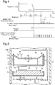
Fig. 4 is a timing diagram representing the relationship among the pressure in the tire, the pressure drop signal transmitted by the normal-time transmission device, and the warning signal transmitted by a sudden-pressure-change transmission device. -
Fig. 5 is a cross-sectional view showing a sudden-pressure-change transmitter. -
Fig. 6 is a cross-sectional view schematically representing the relationship between a deforming portion of a pressure switch and a terminal at the time of elastic deformation of the deforming portion. -
Fig. 7 illustrates an equivalent circuit representing the sudden-pressure-change transmission device. -
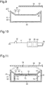
Fig. 8 is a cross-sectional view schematically showing a pressure switch of a comparative example. -
Fig. 9 is a cross-sectional view schematically showing the pressure switch of the comparative example. -
Fig. 10 illustrates an equivalent circuit representing a sudden-pressure-change transmission device of a modification. -
Fig. 11 is a cross-sectional view schematically showing a pressure switch of a modification. -
Fig. 12 is a cross-sectional view schematically showing a sudden-pressure-change transmission device of another modification. -
Figs. 13A to 13D are cross-sectional views each schematically showing a pressure switch of a modification. -
Fig. 14 is a cross-sectional view schematically showing a sudden-pressure-change transmission device of another modification. -
Fig. 15 is a cross-sectional view schematically showing a sudden-pressure-change transmission device of another modification. -
Fig. 16 is a perspective view showing a transmitter of another modification. - A transmitter according to one embodiment will now be described.
- As shown in
Fig. 1 , a tirepressure monitoring device 10 includestransmitters 20 and a tirepressure warning device 60. Each of thetransmitters 20 is attached to one of fourwheel assemblies 12 of a vehicle 11. The tirepressure warning device 60 is arranged in the body of the vehicle 11. Each of thewheel assemblies 12 includes awheel 13 and atire 14. Thetire 14 is mounted on thewheel 13. The tirepressure warning device 60 includes areceiver 61 and awarning device 65. - As shown in
Fig. 2 , each of thetransmitters 20 is integrated with atire valve 16 mounted on arim 15 of one of thewheels 13. To arrange thetransmitter 20 in the internal space of thetire 14, thetransmitter 20 is attached to thewheel 13, on which thetire 14 is mounted. - Each
transmitter 20 includes a normal-time transmission device 20A and a sudden-pressure-change transmission device 20B. The normal-time transmission device 20A and the sudden-pressure-change transmission device 20B are integrated with each other. - As shown in
Fig. 3 , the normal-time transmission devices 20A includes apressure sensor 21, atemperature sensor 22, acontroller 24, a normal-time transmission circuit 25, anantenna 27, and abattery 26. The normal-time transmission device 20A operates using thebattery 26. Thecontroller 24 controls the operation of the normal-time transmission device 20A in an integrated manner. Thepressure sensor 21 detects the pressure in the corresponding tire 14 (the tire internal pressure) and outputs the pressure data of thetire 14 obtained through such detection to thecontroller 24. Thetemperature sensor 22 detects the temperature in the corresponding tire 14 (the tire internal temperature) and outputs the temperature data of thetire 14 obtained through such detection to thecontroller 24. - The
controller 24 is constituted by a microcomputer including a CPU 24a, amemory section 24b (such as a RAM or a ROM), and a timer. Thememory section 24b registers ID codes that carry ID information specific to the respective normal-time transmission devices 20A. The ID codes represent information used to enable thereceiver 61 to identify each of the normal-time transmission devices 20A. Thecontroller 24 generates pressure data, temperature data, and data including the ID code and outputs the data to the normal-time transmission circuit 25. The normal-time transmission circuit 25 modulates the data provided by thecontroller 24 to generate a data signal (an RF signal) and wirelessly transmits the data signal through theantenna 27. The data signal is transmitted as a signal of an RF band (such as the 315 MHz band or 434 MHz band). - The
controller 24 may include dedicated hardware (an application specific integrated circuit: ASIC) that executes at least part of the various processes. That is, thecontroller 24 may be circuitry including 1) one or more processors that operate according to a computer program (software), 2) one or more dedicated hardware circuits such as an ASIC, or 3) a combination thereof. The processor includes a CPU and memories such as a RAM and ROM. The memories store program codes or instructions configured to cause the CPU to execute processes. The memories, or computer readable media, include any type of media that are accessible by general-purpose computers and dedicated computers. - As shown in
Fig. 4 , thecontroller 24 obtains the data of the pressure detected by thepressure sensor 21 intermittently at predetermined obtainment intervals t11. The obtainment interval t11 is, for example, from ten seconds to several tens of seconds. Thecontroller 24 performs normal-time transmission, in which the data signal is transmitted at predetermined intervals. If the pressure the correspondingtire 14 abruptly drops or is excessively low, thecontroller 24 determines that a problem has occurred in thetire 14 and transmits a pressure drop signal. The pressure drop signal may be a signal similar to the data signal or a signal of any format such as a signal carrying a warning flag. - As shown in
Fig. 5 , each of the sudden-pressure-change transmission devices 20B includes abattery 30, atransmission circuit 34, apressure switch 40, aconductive member 50 made of metal, and acase 51. Thecase 51 accommodates the listed components. Thetransmission circuit 34, thebattery 30, and thepressure switch 40 are stacked together. - The
battery 30 is shaped like a disk. Thebattery 30 serves as the electric power supply for thetransmission circuit 34. When supplied with electric power, thetransmission circuit 34 transmits a predetermined warning signal. The warning signal must at least be a signal carrying an ID code. Thetransmission circuit 34 continuously transmits the warning signal as long as thetransmission circuit 34 is supplied with electric power from thebattery 30. Specifically, the ID code carried by the warning signal may be an ID code that is either identical with or different from the ID code of the normal-time transmission device 20A integrated with the sudden-pressure-change transmission device 20B. Thetransmission circuit 34 includes twoterminals terminals - The
pressure switch 40 includes abox 41 made of metal. Thebox 41 is hollow and includes a cylindricalperipheral wall 42, awall section 44, and a deformingportion 45. Thewall section 44 is arranged on one of the opposite ends (the opposite axial ends) of theperipheral wall 42. The deformingportion 45 is arranged on the other one of the opposite ends of theperipheral wall 42. Thewall section 44 has a circular and flat plate-like shape. - The deforming
portion 45 is arranged to dent in the axial direction of theperipheral wall 42 from aperipheral edge 43 of theperipheral wall 42. The deformingportion 45 includes acircular contact portion 46 and aretractable portion 47. Theretractable portion 47 connects the peripheral edge of thecontact portion 46 to theperipheral edge 43 of theperipheral wall 42. The dimension L1 from thecontact portion 46 to thewall section 44 in the axial direction of theperipheral wall 42 is smaller than the dimension L2 from theperipheral edge 43 to thewall section 44 in the axial direction of theperipheral wall 42. That is, the deformingportion 45 is located on the inner side of theperipheral wall 42. - The
pressure switch 40 includesmultiple passages 48. Themultiple passages 48 allow the interior and the exterior of thebox 41 to communicate with each other and extend through thecontact portion 46. - The
transmission circuit 34 serving as a transmitting section and anend face 31 of thebattery 30 face each other. Of the twoterminals end face 31 of thebattery 30. An end face 32 of thebattery 30 opposite to theend face 31 and thewall section 44 of thepressure switch 40 face each other. Theconductive member 50 is arranged between thebattery 30 and thepressure switch 40. Theconductive member 50 is joined to theend face 32 of thebattery 30 and thewall section 44 of thepressure switch 40. - Of the two
terminals transmission circuit 34, the terminal 36, not the terminal 35, has a section that faces the deformingportion 45 of thepressure switch 40. Specifically, the terminal 36 includes afirst section 37 and asecond section 38. Thefirst section 37 extends along thebattery 30 and thepressure switch 40 from thetransmission circuit 34. Thesecond section 38 extends from thefirst section 37 to a position facing thecontact portion 46. - The
second section 38 is arranged in a separate state from thecontact portion 46 of thepressure switch 40. Thesecond section 38 faces the section of thecontact portion 46 in which thepassages 48 are arranged. Specifically, thesecond section 38 facesopenings 49 of thepassages 48. Theopenings 49 are located on the outer side of thebox 41. - The
case 51 is made of an insulating material such as plastic. Thecase 51 includes abattery holding portion 52 and aswitch holding portion 53. Thebattery holding portion 52 holds thebattery 30, and theswitch holding portion 53 holds thepressure switch 40. Thebattery holding portion 52 is arranged not to hamper expansion and contraction of thebattery 30 at the time thebattery 30 is used. The expansion and contraction of thebattery 30 is absorbed through elastic deformation of theconductive member 50. This restricts displacement of thepressure switch 40 caused by the expansion and contraction of thebattery 30. - Although not illustrated, the
case 51 has a hole that allows the interior and the exterior of thecase 51 to communicate with each other. For purposes of illustration, the pressure in thecase 51 is assumed to be always equal to the pressure in thetire 14 in the following description. - As has been described, the
passages 48 allow the interior and the exterior of thebox 41 to communicate with each other. As a result, the pressure in thebox 41 varies in correspondence with pressure variation in thetire 14. If the pressure variation in thetire 14 is small, the pressure in thetire 14 is assumed to be equal to the pressure in thebox 41. When the pressure in thetire 14 and the pressure in thebox 41 are equal, the deformingportion 45 is located on the inner side of theperipheral wall 42 and thecontact portion 46 and the terminal 36 are maintained in the separate state. - As shown in
Fig. 6 , the deformingportion 45 of thepressure switch 40 is elastically deformed by the pressure difference between the interior and the exterior of thebox 41. Specifically, theretractable portion 47 of the deformingportion 45 is elastically deformed when the pressure in thebox 41 is higher than the pressure in the exterior of the box 41 (the pressure in the tire 14) at least by the amount corresponding to a predetermined value. The deformingportion 45 elastically deforms to project outward with respect to theperipheral edge 43 of theperipheral wall 42 in the axial direction of theperipheral wall 42. Such elastic deformation of the deformingportion 45 causes the dimension L1 to be longer than the dimension L2. Thecontact portion 46 and the terminal 36 come into contact with each other through elastic deformation of the deformingportion 45. Thetransmission circuit 34 is thus supplied with electric power and transmits the warning signal. - The aforementioned "predetermined value" can be set to any value in such a range in which deformation of the deforming
portion 45 of thepressure switch 40 is ensured at the time of a sudden pressure change. The sudden pressure change represents a pressure drop exceeding a pressure variation amount (per unit time) at the time of natural pressure drop caused by traveling of the vehicle. The sudden pressure change occurs when, for example, thetire 14 bursts. During the sudden pressure change, in which the pressure in thetire 14 suddenly drops, each of thepassages 48 functions as an orifice such that the pressure in thebox 41 drops more slowly than the pressure in thetire 14. As a result, at the time of the sudden pressure change, a pressure difference is brought about between the pressure in thetire 14 and the pressure in thebox 41. The pressure difference causes elastic deformation of the deformingportion 45. - Considering the above-described condition, the pressure difference between the interior of the
tire 14 and the interior of thebox 41 caused by bursting of thetire 14 under recommended pressure is estimated. The "predetermined value" is set such that the deformingportion 45 is elastically deformed by a pressure difference smaller than the estimated pressure difference. - The pressure difference between the interior and the exterior of the
box 41 necessary for elastically deforming the deformingportion 45 changes depending on the shape of the deformingportion 45, the material of the deformingportion 45, the dimensions of the deformingportion 45, the cross-sectional flow area of thepassages 48, and the volume of thebox 41. The deformingportion 45 is provided such that "predetermined value" is satisfied. This enables elastic deformation of the deformingportion 45 when the pressure in thebox 41 is higher than the pressure in thetire 14 at least by the amount corresponding to the predetermined value. - As has been described, the deforming
portion 45 is configured to be elastically deformed when the pressure in thebox 41 is higher than the pressure in thetire 14 at least by the amount corresponding to the predetermined value. However, tolerance may cause a slight error in the pressure difference necessary for elastic deformation of the deformingportion 45. The "predetermined value" tolerates such slight errors caused by tolerance. - When the deforming
portion 45 is elastically deformed by the pressure difference between the interior and the exterior of thebox 41, theopenings 49 of thepassages 48 are blocked by the terminal 36. The gas in thebox 41 is discharged through the gap between theopenings 49 and the terminal 36. By discharging the gas from thebox 41 through thepassages 48, the pressure in thebox 41 drops slowly. - By blocking the
openings 49 of thepassages 48 with the terminal 36, the opening area of eachopening 49 becomes smaller than that when theopenings 49 of thepassages 48 are not blocked by the terminal 36. This limits the flow rate of the gas discharged through thepassages 48. In other words, in the state in which the pressure in thetire 14 is lower than the pressure in thebox 41, the flow rate of the gas discharged from thebox 41 through thepassages 48 is smaller when the deformingportion 45 and the terminal 36 are in contact with each other than when the deformingportion 45 and the terminal 36 are separate from each other. In the present embodiment, the terminal 36 functions as a flow rate reducing portion. Specifically, if the gap between theopenings 49 and the terminal 36 and thepassages 48 are collectively regarded as a passage that allows the interior of thebox 41 and the interior of thetire 14 to communicate with each other, the cross-sectional flow area of this passage is reduced by the flow rate reducing portion through contact between the deformingportion 45 and the terminal 36. - As the difference between the pressure in the
tire 14 and the pressure in thebox 41 becomes smaller, the elastic force of the deformingportion 45 restores the original shape of the deformingportion 45. The deformingportion 45 and the terminal 36 thus separate from each other, thus ending electric power supply to thetransmission circuit 34. That is, when a sudden pressure change occurs in thetire 14, thetransmission circuit 34 is temporarily supplied with electric power. - Specifically, the time for which elastic deformation of the deforming
portion 45 is maintained, which is the time for which the deformingportion 45 and the terminal 36 are in contact with each other, may be adjusted as needed by changing the shape of the deformingportion 45, the material of the deformingportion 45, the dimensions of the deformingportion 45, or the flow rate of the gas discharged through thepassages 48. The flow rate of the gas discharged through thepassages 48 may be adjusted by changing the cross-sectional flow area of thepassages 48 and the opening area of eachopening 49. In the present embodiment, the shape of the deformingportion 45 is set to maintain elastic deformation of the deformingportion 45 for the time corresponding to the obtainment interval t11 or longer when thetire 14 bursts with the pressure in thetire 14 maintained at the recommended pressure. Specifically, if thebox 41 hasmultiple passages 48 as in the present embodiment, the cross-sectional flow area refers to the sum of the cross-sectional flow areas of thepassages 48. - As shown in
Fig. 7 , thepressure switch 40 is turned on and off depending on the pressure difference. In this manner, thepressure switch 40 functions as a mechanical switch that switches between supplying electric power to thetransmission circuit 34 and blocking such supply of the electric power. - As shown in
Fig. 1 , thereceiver 61 includes areception controller 62, areception circuit 63, and areception antenna 64. Thereception controller 62 of thereceiver 61 is connected to awarning device 65. Thereception controller 62 is constituted by a microcomputer including aCPU 62a and a reception-side memory section 62b (a ROM or a RAM) and controls the operation of thereceiver 61 in an integrated manner. The reception-side memory section 62b memorizes the ID codes of thetransmitters 20. If the normal-time transmission devices 20A use ID codes different from those of the corresponding sudden-pressure-change transmission devices 20B, the respective ID codes are memorized. - The
reception circuit 63 receives the data signals, the pressure drop signals, and the warning signals that are transmitted by thetransmitters 20 through thereception antenna 64. Thereception circuit 63 demodulates the data signals, the pressure drop signals, and the warning signals and outputs the signals to thereception controller 62. - Based on the data signals, the
reception controller 62 obtains the states of thetires 14, such as the pressure in thetire 14 and the temperature in thetire 14. Thereception controller 62 also determines whether a problem has occurred in thetire 14 based on the pressure drop signal and warning signal. If thetire 14 has a problem, thereception controller 62 issues a warning by means of thewarning device 65. - The
warning device 65 may be either a type that issues a warning using sound and vibration, illumination, or a display device that displays the fact that a problem has occurred in thetire 14. - An operation of the
transmitter 20 of the present embodiment will now be described. - As shown in
Fig. 4 , it is assumed that thetire 14 bursts at a point in time T1, thus causing a sudden pressure change in thetire 14. Thecontroller 24 obtains the pressure data at a point in time T0 and then at a point in time T2 in the subsequent cycle. The point in time T1 is between the point in time T0 and the point in time T2. - The
controller 24 detects the sudden pressure change when obtaining the pressure data at the point in time T2, later than the point in time T1. In response to such detection, thecontroller 24 transmits the pressure drop signal. Despite the sudden pressure change, the period from the point in time T1 to the point in time T2 elapses without transmission of the pressure drop signal,. - At the point in time T1, at which the sudden pressure change occurs, the deforming
portion 45 of thepressure switch 40 comes into contact with the terminal 36. This causes thetransmission circuit 34 to transmit the warning signal. Since the time necessary for elastic deformation of the deformingportion 45 is short, the warning signal is transmitted immediately after the sudden pressure change. In other words, the warning signal is transmitted sooner than the pressure drop signal. - As has been described, the normal-
time transmission device 20A intermittently obtains the pressure data. Therefore, even when a sudden pressure change occurs, the normal-time transmission device 20A cannot detect the sudden pressure change unless the pressure data is obtained. This may delay detection of the sudden pressure change. Specifically, there may be cases in which, after the occurrence of a sudden pressure change, thecontroller 24 consumes time substantially equal to the obtainment interval t11 before detection of the sudden pressure change. - In contrast, the sudden-pressure-
change transmission device 20B elastically deforms the deformingportion 45 in response to the pressure difference greater than or equal to the predetermined value. The deformingportion 45 thus comes into contact with the terminal 36 and transmits the warning signal. In other words, the pressure difference mechanically turns on the switch connecting thetransmission circuit 34 to thebattery 30 such that the warning signal is transmitted. As a result, the warning signal is transmitted immediately after the sudden pressure change. - As the time elapses and the pressure difference between the interior and the exterior of the
box 41 becomes smaller, the sudden-pressure-change transmission device 20B stops transmitting the warning signal. Since elastic deformation of the deformingportion 45 is maintained for the time corresponding to the obtainment interval t11 or longer, the normal-time transmission device 20A will have transmitted the pressure drop signal by the point in time at which transmission of the warning signal ends. Therefore, even without transmitting the warning signal, thereceiver 61 continuously obtains the fact that a problem has occurred in thetire 14. - Alternatively, as shown in
Fig. 8 , a pressure switch that has thebox 41 of the present embodiment but without thepassages 48 may be used as apressure switch 200. When under atmospheric pressure, the deformingportion 45 of thepressure switch 200 projects on the outer side of theperipheral wall 42 and is thus in contact with the terminal 36. If thepressure switch 200 is arranged in thetire 14, the pressure in the exterior of thebox 41 is higher than the pressure in thebox 41. This elastically deforms the deformingportion 45 of thepressure switch 200, as shown inFig. 9 , to dent toward the inner side of theperipheral wall 42. The deformingportion 45 thus separates from the terminal 36. In other words, the deformingportion 45 of thepressure switch 200 is deformed by the pressure (the absolute pressure) in the exterior of thebox 41. - If the
tire 14 bursts, the pressure in thetire 14 becomes equal to the atmospheric pressure. As a result, the deformingportion 45 comes into contact with the terminal 36 such that the warning signal is transmitted. - To employ the above-described
pressure switch 200, a sudden-pressure-change transmission device using thepressure switch 200 is first manufactured. The deformingportion 45 and the terminal 36 are in contact with each other until the sudden-pressure-change transmission device is mounted in thewheel assembly 12. Therefore, the warning signal is continuously transmitted until the sudden-pressure-change transmission device is mounted in thewheel assembly 12, thus increasing consumption of the electric power of thebattery 30. Contact between the deformingportion 45 and the terminal 36 may be prevented by maintaining an insulating material between the deformingportion 45 and the terminal 36 until the sudden-pressure-change transmission device is mounted in thewheel assembly 12. However, attachment and detachment of the insulating material is troublesome. Alternatively, locking may be performed to suspend transmission of the warning signal until the sudden-pressure-change transmission device is attached to thewheel assembly 12. Such locking is canceled after the sudden-pressure-change transmission device is mounted in thewheel assembly 12. In this case, a trigger device or the like must be used to selectively cause and cancel such locking, which is also troublesome. - In contrast, the sudden-pressure-
change transmission device 20B of the present embodiment elastically deforms the deformingportion 45 in response to the pressure difference between the interior and the exterior of thebox 41. Therefore, contact between the deformingportion 45 and the terminal 36 is considered unlikely in the period from when the sudden-pressure-change transmission device 20B is manufactured to when the sudden-pressure-change transmission device 20B is mounted in thewheel assembly 12. Even if the deformingportion 45 is elastically deformed and comes into contact with the terminal 36 before the sudden-pressure-change transmission device 20B is mounted in thewheel assembly 12, the deformingportion 45 elastically restores its original shape. This restrains continuous transmission of the warning signal for a prolonged period. - Accordingly, the above-described embodiment has the following advantages.
- (1) The
box 41 has the deformingportion 45. When the pressure in thebox 41 is higher than the pressure in thetire 14 at least by the amount corresponding to the predetermined value, the deformingportion 45 elastically deforms. If a sudden pressure drop occurs in thetire 14, the pressure in thebox 41 temporarily becomes higher than the pressure in thetire 14. Using such pressure increase, the deformingportion 45 is elastically deformed to contact the terminal 36. In response to contact between the deformingportion 45 and the terminal 36, thetransmission circuit 34 transmits the warning signal to the tirepressure warning device 60. The tirepressure warning device 60 is thus caused to issue a warning. Since the warning signal is transmitted in response to elastic deformation of the deformingportion 45, a warning is issued immediately after the sudden pressure change. - (2) When the
contact portion 46 and the terminal 36 come into contact with each other, theopenings 49 of thepassages 48 are blocked by the terminal 36. This limits gas discharge through thepassages 48. As long as thecontact portion 46 and the terminal 36 are in contact with each other, the pressure in thebox 41 is unlikely to drop. This facilitates maintenance of the contact state between thecontact portion 46 and the terminal 36, thus prolonging the time for which the warning signal is transmitted.
The time for which thecontact portion 46 and the terminal 36 are in contact with each other may be prolonged by reducing the cross-sectional flow area of thepassages 48. However, the reduced cross-sectional flow area of thepassages 48 influences the pressure receiving area of the deformingportion 45 and the pressure difference between the interior and the exterior of thebox 41 caused by a sudden pressure change. In this case, the deformingportion 45 may be deformed even by a slight pressure change. Therefore, there may be limitation in setting of the cross-sectional flow area of thepassages 48. If the flow rate of the gas discharged through thepassages 48 is limited only when thecontact portion 46 and the terminal 36 are in contact with each other, the flow rate of the gas discharged through thepassages 48 is reduced while the cross-sectional flow area of thepassages 48 is maintained. - (3) The
transmitter 20 includes the normal-time transmission device 20A in addition to the sudden-pressure-change transmission device 20B. The normal-time transmission device 20A transmits the data signal periodically, thus informing the tirepressure warning device 60 of the pressure in thetire 14. The normal-time transmission device 20A detects the pressure in thetire 14. Therefore, even when the pressure in thetire 14 slowly drops to an excessively low level, the normal-time transmission device 20A is capable of enabling warning. That is, the normal-time transmission device 20A is capable of detecting a problem of thetire 14 that is undetectable by the sudden-pressure-change transmission device 20B, thus causing the tirepressure warning device 60 to issue a warning. As a result, by employing the sudden-pressure-change transmission device 20B and the normal-time transmission device 20A in combination, warning is enabled not only when thetire 14 has a problem caused by a sudden pressure change but also when the pressure in thetire 14 slowly drops to an excessively low level. - (4) By shortening the obtainment interval of obtaining the pressure data from the
pressure sensor 21, the tirepressure warning device 60 is enabled to issue a warning immediately after a sudden pressure change. However, the shortened obtainment interval increases consumption of the electric power of thebattery 26. By using the sudden-pressure-change transmission device 20B, the tirepressure warning device 60 is enabled to issue a warning immediately after a sudden pressure change, without shortening the obtainment interval of the pressure data. - (5) By detecting a sudden pressure change in the
tire 14 by means of thepressure switch 40, the sudden-pressure-change transmission device 20B is enabled to transmit the warning signal without employing a pressure sensor or a controller (a microcomputer). Consumption of the electric power of thebattery 30 is thus smaller than that in a case employing the pressure sensor and the controller. Also, the weight of the sudden-pressure-change transmission device 20B is smaller than that in the case of employing the pressure sensor and the controller. - The above-described embodiment may be modified as follows.
- The above-described embodiment has the sudden-pressure-
change transmission device 20B dedicated to transmit the warning signal at the time of a sudden pressure change. However, the normal-time transmission device 20A may have a function of transmitting the warning signal. Thetransmitter 20 thus lacks the sudden-pressure-change transmission device 20B and includes only the normal-time transmission device 20A. - In this case, as shown in
Fig. 10 , thecontroller 24 and the normal-time transmission circuit 25 of the normal-time transmission device 20A serve as a transmitting section. Specifically, the transmitting section is a component necessary for transmitting the warning signal. If, as described above regarding the above-described embodiment, transmission of the warning signal is accomplished only by thetransmission circuit 34, thetransmission circuit 34 serves as the transmitting section. If, as shown inFig. 10 , the data generated by thecontroller 24 is transmitted from the normal-time transmission circuit 25, thecontroller 24 and the normal-time transmission circuit 25 serve as the transmitting section. - A terminal 81 of a transmitting
section 82 is an interrupt terminal. In this case, the deformingportion 45 comes into contact with the terminal 81 when the pressure in thebox 41 becomes higher than the pressure in thetire 14 at least by the amount corresponding to the predetermined value. Such contact between the deformingportion 45 and the terminal 81 changes the voltage level, thus causing thecontroller 24 to perform an interrupt procedure. The interrupt procedure may be a procedure of transmitting a warning signal from the normal-time transmission device 20A. Alternatively, the interrupt procedure may be a procedure of obtaining the pressure data from thepressure sensor 21. After the pressure data is obtained from thepressure sensor 21, the transmittingsection 82 transmits a pressure drop signal as the warning signal. In either case, when a sudden pressure change occurs, the tirepressure warning device 60 is caused to issue a warning in response to contact between the deformingportion 45 and the terminal 81. - In this case, a common transmission circuit can be employed as the transmission circuit for transmitting the warning signal and the transmission circuit for transmitting the data signal (the normal-time transmission circuit 25). Also, a common battery can be employed as the electric power supply for these transmission circuits. The
transmitter 20 is thus reduced in size compared to the case in which thetransmitter 20 includes both the normal-time transmission device 20A and the sudden-pressure-change transmission device 20B. In addition, this configuration facilitates checking of the operation of thetransmitter 20 using a trigger device or the like. - As shown in
Fig. 11 , thepressure switch 40 may include an accommodatedbody 70 accommodated in thebox 41. The accommodatedbody 70 functions as a flow rate limiting portion and includes a contactingportion 71 and aside wall 72. The contactingportion 71 comes into contact with thecontact portion 46. Theside wall 72 extends from the contactingportion 71 to thewall section 44. The accommodatedbody 70 includes acommunication passage 73 and a through-hole 74. Thecommunication passage 73 extends through the contactingportion 71. The through-hole 74 extends through theside wall 72. Thecommunication passage 73 has a cross-sectional flow area smaller than that of apassage 75 arranged in thecontact portion 46. When thecontact portion 46 and the contactingportion 71 are in contact with each other, thecommunication passage 73 and thepassage 75 communicate with each other. - The terminal 36 has a
terminal passage 76 facing thepassage 75. The cross-sectional flow area of theterminal passage 76 is greater than the cross-sectional flow area of thecommunication passage 73. Elastic deformation of the deformingportion 45 causes communication between thepassage 75 and theterminal passage 76. When a sudden pressure drop occurs in thetire 14 and causes gas discharge from thebox 41 through thepassage 75, the gas discharged through thecommunication passage 73 is discharged through thepassage 75. If the deformingportion 45 and the contactingportion 71 are in contact with each other, the flow rate of the gas discharged from thebox 41 through thepassage 75 depends on the cross-sectional flow area of thecommunication passage 73. In contrast, when the deformingportion 45 and the terminal 36 are in contact with each other, thepassage 75 and theterminal passage 76 communicate with each other. In this state, the flow rate of the gas discharged through thepassage 75 depends on the cross-sectional flow area of theterminal passage 76. The cross-sectional flow area of theterminal passage 76 is greater than the cross-sectional flow area of thecommunication passage 73. The flow rate of the gas discharged through thepassage 75 is thus smaller when the deformingportion 45 and the terminal 36 are separate from each other than when the deformingportion 45 and the terminal 36 are in contact with each other. In other words, the accommodatedbody 70 and theterminal passage 76 function as a flow rate increasing portion. - A sudden pressure drop causes contact between the deforming
portion 45 and the terminal 36. Such contact between the deformingportion 45 and the terminal 36 causes the flow rate of discharged gas to be smaller than that when the deformingportion 45 is in contact with the contactingportion 71. This promotes pressure drop in thebox 41, thus restoring the original shape of the deformingportion 45. Such shape restoration of the deformingportion 45 causes contact between the deformingportion 45 and the contactingportion 71, thus reducing the flow rate of the gas discharged from thebox 41. This promotes increase of the difference between the pressure in thetire 14 and the pressure in thebox 41, thus elastically redeforming the deformingportion 45. By repeating such operation, the deformingportion 45 repeatedly comes into contact with and separates from the terminal 36 in an alternating manner. Such contact and separation are alternately repeated at an interval that becomes shorter as the dropping amount of pressure per unit time becomes greater. The warning signal is transmitted each time the deformingportion 45 comes into contact with the terminal 36. That is, the interval at which the deformingportion 45 comes into contact with the terminal 36 and the interval at which the warning signal is transmitted are synchronous. - By receiving the warning signal, the
reception controller 62 is enabled to issue a warning. Also, with reference to the interval at which thereception controller 62 receives the warning signal, thereception controller 62 obtains the degree of the problem that has occurred in thetire 14. The shorter the interval of warning signal reception, the more sudden pressure drop in thetire 14 becomes. Also, the interval of warning signal reception is used by thereception controller 62 to calculate the dropping amount (the drop rate) of pressure per unit time. - The locations of the
transmission circuit 34, thebattery 30, and thepressure switch 40 may be changed as needed. For example, as shown inFig. 12 , theperipheral wall 42 and a side surface of thebattery 30 may face each other, and another side surface of thebattery 30 and thetransmission circuit 34 may face each other. - As shown in
Fig. 13A , the terminal 36 may include atubular portion 84 projecting from thesecond section 38 toward thecontact portion 46. Thetubular portion 84 extends from the terminal 36 toward thecontact portion 46. Aterminal passage 85 is arranged in a section of thetubular portion 84 to cause the interior and the exterior of thetubular portion 84 to communicate with each other. The cross-sectional flow area of theterminal passage 85 is smaller than the cross-sectional flow area of eachpassage 48. - The deforming
portion 45 elastically deforms and comes into contact with thetubular portion 84. In this state, thepassages 48 communicate with the range surrounded by thetubular portion 84 and thecontact portion 46. The range and the interior of thetire 14 communicate with each other through theterminal passage 85. Since the cross-sectional flow area of theterminal passage 85 is smaller than the cross-sectional flow area of eachpassage 48, the flow rate of the gas discharged through thepassages 48 is small when the deformingportion 45 and thecontact portion 46 are in contact with each other. In this case, thetubular portion 84 and theterminal passage 85 function as a flow rate reducing portion. - As shown in
Fig. 13B , the terminal 36 may include aterminal passage 88 having a cross-sectional flow area smaller than the cross-sectional flow area of apassage 87 arranged in thecontact portion 46. Theterminal passage 88 is located at such a position where, when the deformingportion 45 and the terminal 36 come into contact with each other, theterminal passage 88 communicates with thepassage 87. In this case, theterminal passage 88 functions as a flow rate reducing portion to reduce the flow rate of the gas discharged through thepassage 87 when the deformingportion 45 and the terminal 36 are in contact with each other. - As shown in
Fig. 13C , the terminal 36 may have aterminal passage 91. When the deformingportion 45 and the terminal 36 come into contact with each other, theterminal passage 91 becomes overlapped with a section of apassage 90 arranged in thecontact portion 46. Theterminal passage 91 has a cross-sectional flow area not less than the cross-sectional flow area of thepassage 90. The area by which theterminal passage 91 and thepassage 90 are overlapped with each other when the deformingportion 45 is in contact with the terminal 36 is less than the cross-sectional flow area of thepassage 90. Therefore, theterminal passage 91 functions as a flow rate reducing portion to reduce the flow rate of the gas discharged through thepassage 90 when the deformingportion 45 and thecontact portion 46 are in contact with each other. - As shown in
Fig. 13D , the terminal 36 may include aterminal passage 93. When the deformingportion 45 and the terminal 36 come into contact with each other, theterminal passage 93 communicates with some of thepassages 48 arranged in thecontact portion 46. Theterminal passage 93 functions as a flow rate reducing portion to reduce the flow rate of the gas discharged through thepassages 48 when the deformingportion 45 and thecontact portion 46 are in contact with each other. - As shown in
Fig. 14 , thepassages 48 may be arranged in thewall section 44. Alternatively, thepassages 48 may be arranged in either theperipheral wall 42 or theretractable portion 47. - As shown in
Fig. 15 , apassage 96 of thepressure switch 40 may have an air-permeable filter 97. Since thefilter 97 causes pressure loss, the air permeability of thefilter 97 is taken into consideration when setting the cross-sectional flow area of thepassage 96. - The
transmitter 20 may be attached to the wheel assembly in any manners. For example, thetransmitter 20 may be bonded to thetire 14. - The
transmitter 20 may be configured to include the sudden-pressure-change transmission device 20B but not the normal-time transmission device 20A. Even in this case, when a sudden pressure change occurs in thetire 14, the warning signal transmitted by the sudden-pressure-change transmission device 20B causes thewarning device 65 to issue a warning. Further, since the sudden-pressure-change transmission device 20B transmits the warning signal temporarily at the time of a sudden pressure change, the sudden-pressure-change transmission device 20B transmits signals less frequently than the normal-time transmission device 20A. Therefore, the sudden-pressure-change transmission device 20B consumes less electric power than the normal-time transmission device 20A. This prolongs the life of thetransmitter 20 if a battery with the capacity equal to that of thebattery 26 of the normal-time transmission device 20A is used as thebattery 30 of the sudden-pressure-change transmission device 20B. - Also, the sudden-pressure-
change transmission device 20B has a smaller number of components than the normal-time transmission device 20A. This reduces the cost for manufacturing thetransmitter 20. - The
box 41 may have any shape as long as thebox 41 has a deforming portion and the deforming portion is deformable by the pressure difference between the interior and the exterior of thebox 41. For example, theperipheral wall 42 may have a rectangular tubular shape. - The deforming portion does not necessarily have to be made of metal as long as the deforming portion is conductive and elastically deformable. For example, the deforming portion may be made of elastically deformable conductive plastic or made of an elastically deformable plastic material having a metal-plated or conductive-coated surface or an elastically deformable plastic material having a metal mesh attached thereto. The deforming portion does not necessarily have to be conductive as a whole, if it is conductive at least in the section that contacts the terminal 36. Compared to a deforming portion made of metal, the listed deforming portions are light-weighted and enable shape setting with improved flexibility. Further, these deforming portions are easier to machine than a deforming portion made of metal.
- The
passages 48 may be replaced by asingle passage 48. - The
wall section 44 of thepressure switch 40 and theend face 32 of thebattery 30 may be in direct contact with each other. In this case, theconductive member 50 is not employed. - The
peripheral wall 42 and thewall section 44 of thepressure switch 40 may be made of any material other than metal, such as plastic. That is, at least the deformingportion 45 of thepressure switch 40 must be made of metal. - The normal-
time transmission device 20A and the sudden-pressure-change transmission device 20B do not necessarily have to be integrated with each other but may be attached to thewheel assembly 12 independently from each other as shown inFig. 16 . For example, the normal-time transmission device 20A and the sudden-pressure-change transmission device 20B may each be attached to thewheel assembly 12 by being integrated with thetire valve 16 or being bonded to the inner side of thewheel 13 or the inner side of thetire 14. That is, the normal-time transmission device 20A and the sudden-pressure-change transmission device 20B may be attached at any site as long as thetransmission devices tire 14 and capable of detecting the pressure in thetire 14. Specifically, by attaching the normal-time transmission device 20A and the sudden-pressure-change transmission device 20B at opposite positions with respect to the rotation axis of thewheel 13, a light-weighted balance weight can be employed for balance adjustment of thetire 14. - The tire pressure warning device may be any device as long as the device has a function of receiving a warning signal and a function of issuing a warning, such as a portable terminal carried by an occupant of the vehicle.
- The vehicle may be a motorcycle or a vehicle having five or more wheel assemblies.
- Signals of the 2.4 GHz band may be used as the data signal, the pressure drop signal, and the warning signal.
- The data signal does not necessarily have to carry the temperature data. In this case, the normal-
time transmission device 20A may lack thetemperature sensor 22. - The
transmitter 20 may transmit the data signal at a constant position (for example, the lowermost position). Based on the correlative relationship between the timing at which thereception controller 62 receives the data signal from thetransmitter 20 and the rotation angle of thewheel assembly 12 at the time of reception of the data signal, thereception controller 62 may determine which of thewheel assemblies 12 thetransmitter 20 is mounted in (auto-location). Specifically, the rotation angle of thewheel assembly 12 is obtained from an anti-lock braking system (ABS). In this case, by employing a common ID code for each normal-time transmission device 20A and the associated sudden-pressure-change transmission device 20B, thereceiver 61 can determine which of thewheel assemblies 12 the sudden-pressure-change transmission device 20B that has transmitted the data signal is mounted in. That is, thereceiver 61 can determine which of thetires 14 of thewheel assemblies 12 has a problem. Specifically, even if each normal-time transmission device 20A and the associated sudden-pressure-change transmission device 20B employ different ID codes, the same effect as the above-described effect is obtained by memorizing the ID codes as associated with each other in the reception-side memory section 62b. - The
box 41 or the terminal 35, 36 may be used as an antenna of thetransmission circuit 34. - 14...Tire, 20...Transmitter, 34...Transmission Circuit (Transmitting Section), 36...Terminal (Flow Rate Reducing Portion), 40...Pressure Switch, 41...Box, 45...Deforming Portion, 48...Passage, 60...Tire Pressure Warning Device
Claims (5)
- A transmitter adapted to be arranged in a tire to cause a tire pressure warning device to issue a warning, the transmitter comprising:a transmitting section, which has a terminal; anda pressure switch, whereinthe pressure switch includes a hollow box and a passage that causes an interior of the box and an interior of the tire to communicate with each other,the box includes a conductive deforming portion, which is configured to be separate from the terminal of the transmitting section when a difference between a pressure in the box and a pressure in the tire is less than a predetermined value and to be elastically deformed to contact the terminal when the pressure in the box is higher than the pressure in the tire at least by the predetermined value, andthe transmitting section is configured to transmit a warning signal that causes the tire pressure warning device to issue a warning in response to contact between the deforming portion and the terminal.
- The transmitter according to claim 1, further comprising a flow rate reducing portion, which is configured to, in a state in which the pressure in the tire is lower than the pressure in the box, cause a flow rate of gas discharged from the box through the passage to be smaller when the deforming portion and the terminal are in contact with each other than when the deforming portion and the terminal are separate from each other.
- The transmitter according to claim 1 or 2, wherein
the passage is provided in the deforming portion, and
the terminal is configured to limit the flow rate of the gas discharged from the box through the passage when the terminal contacts the deforming portion. - The transmitter according to claim 1, further comprising a flow rate increasing portion, which is configured to, in a state in which the pressure in the tire is lower than the pressure in the box, cause a flow rate of gas discharged from the box through the passage to be smaller when the deforming portion and the terminal are separate from each other than when the deforming portion and the terminal are in contact with each other.
- The transmitter according to claim 4, wherein
the passage is provided in the deforming portion, and
the flow rate increasing portion includes a flow rate limiting portion arranged in the box, and
the flow rate limiting portion is configured to limit the flow rate of the gas discharged from the box through the passage when the deforming portion and the terminal are separate from each other.
Applications Claiming Priority (1)
| Application Number | Priority Date | Filing Date | Title |
|---|---|---|---|
| PCT/JP2017/038777 WO2019082353A1 (en) | 2017-10-26 | 2017-10-26 | TRANSMITTER |
Publications (3)
| Publication Number | Publication Date |
|---|---|
| EP3501859A1 true EP3501859A1 (en) | 2019-06-26 |
| EP3501859A4 EP3501859A4 (en) | 2020-02-12 |
| EP3501859B1 EP3501859B1 (en) | 2022-05-18 |
Family
ID=66246319
Family Applications (1)
| Application Number | Title | Priority Date | Filing Date |
|---|---|---|---|
| EP17912352.6A Not-in-force EP3501859B1 (en) | 2017-10-26 | 2017-10-26 | Transmitter |
Country Status (5)
| Country | Link |
|---|---|
| US (1) | US11794531B2 (en) |
| EP (1) | EP3501859B1 (en) |
| JP (1) | JP6817332B2 (en) |
| CN (1) | CN109963729B (en) |
| WO (1) | WO2019082353A1 (en) |
Families Citing this family (1)
| Publication number | Priority date | Publication date | Assignee | Title |
|---|---|---|---|---|
| JP7356570B2 (en) * | 2020-03-03 | 2023-10-04 | アルプスアルパイン株式会社 | tire mount sensor |
Family Cites Families (15)
| Publication number | Priority date | Publication date | Assignee | Title |
|---|---|---|---|---|
| JPS5722027U (en) * | 1980-07-15 | 1982-02-04 | ||
| FR2614240B1 (en) * | 1987-04-23 | 1989-07-28 | Jaeger | MONITORING AND ALARM DEVICE FOR VEHICLE TIRES. |
| JP2505125Y2 (en) | 1990-11-30 | 1996-07-24 | 太平洋工業株式会社 | Tire air pressure alarm pressure detector |
| JPH0886712A (en) * | 1993-07-29 | 1996-04-02 | Bridgestone Corp | Pneumatic sensor for tire and its manufacture |
| JPH11348516A (en) * | 1998-06-05 | 1999-12-21 | Pacific Ind Co Ltd | Tire pneumatic pressure alarm device |
| JP2000118214A (en) * | 1998-10-09 | 2000-04-25 | Kyowa Electron Instr Co Ltd | Tire pressure monitoring device |
| JP2004330887A (en) | 2003-05-08 | 2004-11-25 | Honda Motor Co Ltd | Pressure switch and tire pressure monitoring device using pressure switch |
| US7348878B2 (en) * | 2005-09-29 | 2008-03-25 | International Truck Intellectual Property Company, Llc | Tire pressure monitoring system with permanent tire identification |
| WO2008133314A1 (en) * | 2007-04-24 | 2008-11-06 | Bridgestone Corporation | Sensor module |
| JP2009173148A (en) * | 2008-01-24 | 2009-08-06 | Topy Ind Ltd | Tire monitoring system and monitoring method |
| EP2423007B1 (en) * | 2009-04-24 | 2016-09-07 | Toyota Jidosha Kabushiki Kaisha | Device for monitoring tire air pressure |
| CN201890097U (en) * | 2010-11-09 | 2011-07-06 | 翔鑫科技股份有限公司 | tire pressure monitoring device |
| CN103317978A (en) * | 2012-03-21 | 2013-09-25 | 李尔汽车电子电器(上海)有限公司 | Tire pressure monitoring device |
| JP2014091344A (en) | 2012-10-31 | 2014-05-19 | Yokohama Rubber Co Ltd:The | Tire condition monitoring system and monitoring device |
| CN106507669B (en) * | 2015-06-26 | 2018-08-28 | 太平洋工业株式会社 | wheel position determining device |
-
2017
- 2017-10-26 WO PCT/JP2017/038777 patent/WO2019082353A1/en not_active Ceased
- 2017-10-26 JP JP2018557153A patent/JP6817332B2/en not_active Expired - Fee Related
- 2017-10-26 EP EP17912352.6A patent/EP3501859B1/en not_active Not-in-force
- 2017-10-26 CN CN201780029362.5A patent/CN109963729B/en not_active Expired - Fee Related
- 2017-10-26 US US16/306,642 patent/US11794531B2/en active Active
Also Published As
| Publication number | Publication date |
|---|---|
| EP3501859A4 (en) | 2020-02-12 |
| US20210268848A1 (en) | 2021-09-02 |
| WO2019082353A1 (en) | 2019-05-02 |
| JP6817332B2 (en) | 2021-01-20 |
| CN109963729A (en) | 2019-07-02 |
| EP3501859B1 (en) | 2022-05-18 |
| US11794531B2 (en) | 2023-10-24 |
| JPWO2019082353A1 (en) | 2020-09-10 |
| CN109963729B (en) | 2021-01-26 |
Similar Documents
| Publication | Publication Date | Title |
|---|---|---|
| EP1681660A1 (en) | Tire sensor device and tire information transmission method | |
| US6549125B2 (en) | Tire condition sensor unit mounting arrangement | |
| EP1976714B1 (en) | Tire monitor system having tire valve antenna | |
| US11198336B2 (en) | Transmission and receiving arrangement for a tire pressure detection device | |
| JP2006062414A (en) | Sensor unit | |
| US8217776B2 (en) | Tire pressure sensor location identification | |
| EP3165384B1 (en) | Tire state detection device | |
| CN102612441B (en) | Transmission device for transmitting information about tire condition and tire condition monitoring system | |
| EP3501859B1 (en) | Transmitter | |
| EP3162596B1 (en) | Device for determining wheel rotational position | |
| AU2013275529B2 (en) | Condition detection device | |
| CN115943089B (en) | Continuous alarm transmission associated with vehicle-mounted wireless sensor devices | |
| CN116141881B (en) | Tire position determination system | |
| EP1268226B1 (en) | Tire condition sensor unit mounting arrangement | |
| US20070194895A1 (en) | Tire pressure monitoring system and sensor therefor | |
| EP1792757B1 (en) | Tire condition monitoring system | |
| US20090224903A1 (en) | Tire air pressure monitoring system | |
| US6935169B2 (en) | Tire pressure sensor array | |
| US20220417927A1 (en) | Tire pressure detection system with single antenna | |
| JP4787546B2 (en) | Tire management system | |
| JP4367292B2 (en) | Control adjustment mechanism and control device | |
| JP2004090772A (en) | Wheel status monitoring system | |
| CN121650377A (en) | A device for detecting tire pressure, an inner tube or rim for receiving the device, and an inner tube or rim having the device. | |
| KR20090005198U (en) | Pressure sensor for tire pressure measurement and tire air pressure monitoring system | |
| KR101661293B1 (en) | Tire pressure measurement module and valve cap |
Legal Events
| Date | Code | Title | Description |
|---|---|---|---|
| STAA | Information on the status of an ep patent application or granted ep patent |
Free format text: STATUS: UNKNOWN |
|
| STAA | Information on the status of an ep patent application or granted ep patent |
Free format text: STATUS: THE INTERNATIONAL PUBLICATION HAS BEEN MADE |
|
| PUAI | Public reference made under article 153(3) epc to a published international application that has entered the european phase |
Free format text: ORIGINAL CODE: 0009012 |
|
| STAA | Information on the status of an ep patent application or granted ep patent |
Free format text: STATUS: REQUEST FOR EXAMINATION WAS MADE |
|
| 17P | Request for examination filed |
Effective date: 20181212 |
|
| AK | Designated contracting states |
Kind code of ref document: A1 Designated state(s): AL AT BE BG CH CY CZ DE DK EE ES FI FR GB GR HR HU IE IS IT LI LT LU LV MC MK MT NL NO PL PT RO RS SE SI SK SM TR |
|
| AX | Request for extension of the european patent |
Extension state: BA ME |
|
| A4 | Supplementary search report drawn up and despatched |
Effective date: 20200113 |
|
| RIC1 | Information provided on ipc code assigned before grant |
Ipc: B60C 23/02 20060101AFI20200107BHEP Ipc: B60C 23/04 20060101ALI20200107BHEP |
|
| DAV | Request for validation of the european patent (deleted) | ||
| DAX | Request for extension of the european patent (deleted) | ||
| GRAP | Despatch of communication of intention to grant a patent |
Free format text: ORIGINAL CODE: EPIDOSNIGR1 |
|
| STAA | Information on the status of an ep patent application or granted ep patent |
Free format text: STATUS: GRANT OF PATENT IS INTENDED |
|
| INTG | Intention to grant announced |
Effective date: 20211213 |
|
| GRAS | Grant fee paid |
Free format text: ORIGINAL CODE: EPIDOSNIGR3 |
|
| GRAA | (expected) grant |
Free format text: ORIGINAL CODE: 0009210 |
|
| STAA | Information on the status of an ep patent application or granted ep patent |
Free format text: STATUS: THE PATENT HAS BEEN GRANTED |
|
| AK | Designated contracting states |
Kind code of ref document: B1 Designated state(s): AL AT BE BG CH CY CZ DE DK EE ES FI FR GB GR HR HU IE IS IT LI LT LU LV MC MK MT NL NO PL PT RO RS SE SI SK SM TR |
|
| REG | Reference to a national code |
Ref country code: GB Ref legal event code: FG4D |
|
| REG | Reference to a national code |
Ref country code: CH Ref legal event code: EP |
|
| REG | Reference to a national code |
Ref country code: IE Ref legal event code: FG4D |
|
| REG | Reference to a national code |
Ref country code: DE Ref legal event code: R096 Ref document number: 602017057755 Country of ref document: DE |
|
| REG | Reference to a national code |
Ref country code: AT Ref legal event code: REF Ref document number: 1492964 Country of ref document: AT Kind code of ref document: T Effective date: 20220615 |
|
| REG | Reference to a national code |
Ref country code: LT Ref legal event code: MG9D |
|
| REG | Reference to a national code |
Ref country code: NL Ref legal event code: MP Effective date: 20220518 |
|
| REG | Reference to a national code |
Ref country code: AT Ref legal event code: MK05 Ref document number: 1492964 Country of ref document: AT Kind code of ref document: T Effective date: 20220518 |
|
| PG25 | Lapsed in a contracting state [announced via postgrant information from national office to epo] |
Ref country code: SE Free format text: LAPSE BECAUSE OF FAILURE TO SUBMIT A TRANSLATION OF THE DESCRIPTION OR TO PAY THE FEE WITHIN THE PRESCRIBED TIME-LIMIT Effective date: 20220518 Ref country code: PT Free format text: LAPSE BECAUSE OF FAILURE TO SUBMIT A TRANSLATION OF THE DESCRIPTION OR TO PAY THE FEE WITHIN THE PRESCRIBED TIME-LIMIT Effective date: 20220919 Ref country code: NO Free format text: LAPSE BECAUSE OF FAILURE TO SUBMIT A TRANSLATION OF THE DESCRIPTION OR TO PAY THE FEE WITHIN THE PRESCRIBED TIME-LIMIT Effective date: 20220818 Ref country code: NL Free format text: LAPSE BECAUSE OF FAILURE TO SUBMIT A TRANSLATION OF THE DESCRIPTION OR TO PAY THE FEE WITHIN THE PRESCRIBED TIME-LIMIT Effective date: 20220518 Ref country code: LT Free format text: LAPSE BECAUSE OF FAILURE TO SUBMIT A TRANSLATION OF THE DESCRIPTION OR TO PAY THE FEE WITHIN THE PRESCRIBED TIME-LIMIT Effective date: 20220518 Ref country code: HR Free format text: LAPSE BECAUSE OF FAILURE TO SUBMIT A TRANSLATION OF THE DESCRIPTION OR TO PAY THE FEE WITHIN THE PRESCRIBED TIME-LIMIT Effective date: 20220518 Ref country code: GR Free format text: LAPSE BECAUSE OF FAILURE TO SUBMIT A TRANSLATION OF THE DESCRIPTION OR TO PAY THE FEE WITHIN THE PRESCRIBED TIME-LIMIT Effective date: 20220819 Ref country code: FI Free format text: LAPSE BECAUSE OF FAILURE TO SUBMIT A TRANSLATION OF THE DESCRIPTION OR TO PAY THE FEE WITHIN THE PRESCRIBED TIME-LIMIT Effective date: 20220518 Ref country code: ES Free format text: LAPSE BECAUSE OF FAILURE TO SUBMIT A TRANSLATION OF THE DESCRIPTION OR TO PAY THE FEE WITHIN THE PRESCRIBED TIME-LIMIT Effective date: 20220518 Ref country code: BG Free format text: LAPSE BECAUSE OF FAILURE TO SUBMIT A TRANSLATION OF THE DESCRIPTION OR TO PAY THE FEE WITHIN THE PRESCRIBED TIME-LIMIT Effective date: 20220818 Ref country code: AT Free format text: LAPSE BECAUSE OF FAILURE TO SUBMIT A TRANSLATION OF THE DESCRIPTION OR TO PAY THE FEE WITHIN THE PRESCRIBED TIME-LIMIT Effective date: 20220518 |
|
| PG25 | Lapsed in a contracting state [announced via postgrant information from national office to epo] |
Ref country code: RS Free format text: LAPSE BECAUSE OF FAILURE TO SUBMIT A TRANSLATION OF THE DESCRIPTION OR TO PAY THE FEE WITHIN THE PRESCRIBED TIME-LIMIT Effective date: 20220518 Ref country code: PL Free format text: LAPSE BECAUSE OF FAILURE TO SUBMIT A TRANSLATION OF THE DESCRIPTION OR TO PAY THE FEE WITHIN THE PRESCRIBED TIME-LIMIT Effective date: 20220518 Ref country code: LV Free format text: LAPSE BECAUSE OF FAILURE TO SUBMIT A TRANSLATION OF THE DESCRIPTION OR TO PAY THE FEE WITHIN THE PRESCRIBED TIME-LIMIT Effective date: 20220518 Ref country code: IS Free format text: LAPSE BECAUSE OF FAILURE TO SUBMIT A TRANSLATION OF THE DESCRIPTION OR TO PAY THE FEE WITHIN THE PRESCRIBED TIME-LIMIT Effective date: 20220918 |
|
| PG25 | Lapsed in a contracting state [announced via postgrant information from national office to epo] |
Ref country code: SM Free format text: LAPSE BECAUSE OF FAILURE TO SUBMIT A TRANSLATION OF THE DESCRIPTION OR TO PAY THE FEE WITHIN THE PRESCRIBED TIME-LIMIT Effective date: 20220518 Ref country code: SK Free format text: LAPSE BECAUSE OF FAILURE TO SUBMIT A TRANSLATION OF THE DESCRIPTION OR TO PAY THE FEE WITHIN THE PRESCRIBED TIME-LIMIT Effective date: 20220518 Ref country code: RO Free format text: LAPSE BECAUSE OF FAILURE TO SUBMIT A TRANSLATION OF THE DESCRIPTION OR TO PAY THE FEE WITHIN THE PRESCRIBED TIME-LIMIT Effective date: 20220518 Ref country code: EE Free format text: LAPSE BECAUSE OF FAILURE TO SUBMIT A TRANSLATION OF THE DESCRIPTION OR TO PAY THE FEE WITHIN THE PRESCRIBED TIME-LIMIT Effective date: 20220518 Ref country code: DK Free format text: LAPSE BECAUSE OF FAILURE TO SUBMIT A TRANSLATION OF THE DESCRIPTION OR TO PAY THE FEE WITHIN THE PRESCRIBED TIME-LIMIT Effective date: 20220518 Ref country code: CZ Free format text: LAPSE BECAUSE OF FAILURE TO SUBMIT A TRANSLATION OF THE DESCRIPTION OR TO PAY THE FEE WITHIN THE PRESCRIBED TIME-LIMIT Effective date: 20220518 |
|
| REG | Reference to a national code |
Ref country code: DE Ref legal event code: R097 Ref document number: 602017057755 Country of ref document: DE |
|
| PLBE | No opposition filed within time limit |
Free format text: ORIGINAL CODE: 0009261 |
|
| STAA | Information on the status of an ep patent application or granted ep patent |
Free format text: STATUS: NO OPPOSITION FILED WITHIN TIME LIMIT |
|
| PG25 | Lapsed in a contracting state [announced via postgrant information from national office to epo] |
Ref country code: AL Free format text: LAPSE BECAUSE OF FAILURE TO SUBMIT A TRANSLATION OF THE DESCRIPTION OR TO PAY THE FEE WITHIN THE PRESCRIBED TIME-LIMIT Effective date: 20220518 |
|
| 26N | No opposition filed |
Effective date: 20230221 |
|
| PG25 | Lapsed in a contracting state [announced via postgrant information from national office to epo] |
Ref country code: SI Free format text: LAPSE BECAUSE OF FAILURE TO SUBMIT A TRANSLATION OF THE DESCRIPTION OR TO PAY THE FEE WITHIN THE PRESCRIBED TIME-LIMIT Effective date: 20220518 Ref country code: MC Free format text: LAPSE BECAUSE OF FAILURE TO SUBMIT A TRANSLATION OF THE DESCRIPTION OR TO PAY THE FEE WITHIN THE PRESCRIBED TIME-LIMIT Effective date: 20220518 |
|
| REG | Reference to a national code |
Ref country code: CH Ref legal event code: PL |
|
| REG | Reference to a national code |
Ref country code: BE Ref legal event code: MM Effective date: 20221031 |
|
| PG25 | Lapsed in a contracting state [announced via postgrant information from national office to epo] |
Ref country code: LU Free format text: LAPSE BECAUSE OF NON-PAYMENT OF DUE FEES Effective date: 20221026 |
|
| PG25 | Lapsed in a contracting state [announced via postgrant information from national office to epo] |
Ref country code: LI Free format text: LAPSE BECAUSE OF NON-PAYMENT OF DUE FEES Effective date: 20221031 Ref country code: CH Free format text: LAPSE BECAUSE OF NON-PAYMENT OF DUE FEES Effective date: 20221031 |
|
| PG25 | Lapsed in a contracting state [announced via postgrant information from national office to epo] |
Ref country code: BE Free format text: LAPSE BECAUSE OF NON-PAYMENT OF DUE FEES Effective date: 20221031 |
|
| PG25 | Lapsed in a contracting state [announced via postgrant information from national office to epo] |
Ref country code: IE Free format text: LAPSE BECAUSE OF NON-PAYMENT OF DUE FEES Effective date: 20221026 |
|
| PGFP | Annual fee paid to national office [announced via postgrant information from national office to epo] |
Ref country code: GB Payment date: 20230907 Year of fee payment: 7 |
|
| PGFP | Annual fee paid to national office [announced via postgrant information from national office to epo] |
Ref country code: FR Payment date: 20230911 Year of fee payment: 7 |
|
| PG25 | Lapsed in a contracting state [announced via postgrant information from national office to epo] |
Ref country code: IT Free format text: LAPSE BECAUSE OF FAILURE TO SUBMIT A TRANSLATION OF THE DESCRIPTION OR TO PAY THE FEE WITHIN THE PRESCRIBED TIME-LIMIT Effective date: 20220518 |
|
| PGFP | Annual fee paid to national office [announced via postgrant information from national office to epo] |
Ref country code: DE Payment date: 20230830 Year of fee payment: 7 |
|
| PG25 | Lapsed in a contracting state [announced via postgrant information from national office to epo] |
Ref country code: HU Free format text: LAPSE BECAUSE OF FAILURE TO SUBMIT A TRANSLATION OF THE DESCRIPTION OR TO PAY THE FEE WITHIN THE PRESCRIBED TIME-LIMIT; INVALID AB INITIO Effective date: 20171026 |
|
| PG25 | Lapsed in a contracting state [announced via postgrant information from national office to epo] |
Ref country code: CY Free format text: LAPSE BECAUSE OF FAILURE TO SUBMIT A TRANSLATION OF THE DESCRIPTION OR TO PAY THE FEE WITHIN THE PRESCRIBED TIME-LIMIT Effective date: 20220511 |
|
| PG25 | Lapsed in a contracting state [announced via postgrant information from national office to epo] |
Ref country code: MK Free format text: LAPSE BECAUSE OF FAILURE TO SUBMIT A TRANSLATION OF THE DESCRIPTION OR TO PAY THE FEE WITHIN THE PRESCRIBED TIME-LIMIT Effective date: 20220511 |
|
| PG25 | Lapsed in a contracting state [announced via postgrant information from national office to epo] |
Ref country code: MT Free format text: LAPSE BECAUSE OF FAILURE TO SUBMIT A TRANSLATION OF THE DESCRIPTION OR TO PAY THE FEE WITHIN THE PRESCRIBED TIME-LIMIT Effective date: 20220511 |
|
| PG25 | Lapsed in a contracting state [announced via postgrant information from national office to epo] |
Ref country code: BG Free format text: LAPSE BECAUSE OF FAILURE TO SUBMIT A TRANSLATION OF THE DESCRIPTION OR TO PAY THE FEE WITHIN THE PRESCRIBED TIME-LIMIT Effective date: 20220518 |
|
| PG25 | Lapsed in a contracting state [announced via postgrant information from national office to epo] |
Ref country code: BG Free format text: LAPSE BECAUSE OF FAILURE TO SUBMIT A TRANSLATION OF THE DESCRIPTION OR TO PAY THE FEE WITHIN THE PRESCRIBED TIME-LIMIT Effective date: 20220518 |
|
| REG | Reference to a national code |
Ref country code: DE Ref legal event code: R119 Ref document number: 602017057755 Country of ref document: DE |
|
| GBPC | Gb: european patent ceased through non-payment of renewal fee |
Effective date: 20241026 |
|
| PG25 | Lapsed in a contracting state [announced via postgrant information from national office to epo] |
Ref country code: DE Free format text: LAPSE BECAUSE OF NON-PAYMENT OF DUE FEES Effective date: 20250501 |
|
| PG25 | Lapsed in a contracting state [announced via postgrant information from national office to epo] |
Ref country code: GB Free format text: LAPSE BECAUSE OF NON-PAYMENT OF DUE FEES Effective date: 20241026 |
|
| PG25 | Lapsed in a contracting state [announced via postgrant information from national office to epo] |
Ref country code: FR Free format text: LAPSE BECAUSE OF NON-PAYMENT OF DUE FEES Effective date: 20241031 |
|
| PG25 | Lapsed in a contracting state [announced via postgrant information from national office to epo] |
Ref country code: TR Free format text: LAPSE BECAUSE OF FAILURE TO SUBMIT A TRANSLATION OF THE DESCRIPTION OR TO PAY THE FEE WITHIN THE PRESCRIBED TIME-LIMIT Effective date: 20220518 |