EP3501751A1 - Dispositif d'enfoncement - Google Patents
Dispositif d'enfoncement Download PDFInfo
- Publication number
- EP3501751A1 EP3501751A1 EP17209518.4A EP17209518A EP3501751A1 EP 3501751 A1 EP3501751 A1 EP 3501751A1 EP 17209518 A EP17209518 A EP 17209518A EP 3501751 A1 EP3501751 A1 EP 3501751A1
- Authority
- EP
- European Patent Office
- Prior art keywords
- motor
- energy
- support structure
- housing
- driving
- Prior art date
- Legal status (The legal status is an assumption and is not a legal conclusion. Google has not performed a legal analysis and makes no representation as to the accuracy of the status listed.)
- Withdrawn
Links
Images


Classifications
-
- B—PERFORMING OPERATIONS; TRANSPORTING
- B25—HAND TOOLS; PORTABLE POWER-DRIVEN TOOLS; MANIPULATORS
- B25C—HAND-HELD NAILING OR STAPLING TOOLS; MANUALLY OPERATED PORTABLE STAPLING TOOLS
- B25C1/00—Hand-held nailing tools; Nail feeding devices
- B25C1/06—Hand-held nailing tools; Nail feeding devices operated by electric power
-
- B—PERFORMING OPERATIONS; TRANSPORTING
- B25—HAND TOOLS; PORTABLE POWER-DRIVEN TOOLS; MANIPULATORS
- B25F—COMBINATION OR MULTI-PURPOSE TOOLS NOT OTHERWISE PROVIDED FOR; DETAILS OR COMPONENTS OF PORTABLE POWER-DRIVEN TOOLS NOT PARTICULARLY RELATED TO THE OPERATIONS PERFORMED AND NOT OTHERWISE PROVIDED FOR
- B25F5/00—Details or components of portable power-driven tools not particularly related to the operations performed and not otherwise provided for
- B25F5/006—Vibration damping means
Definitions
- the application relates to a device for driving a fastener into a substrate.
- Such devices usually have a piston for transmitting energy to the fastener.
- the energy required for this must be provided in a very short time, which is why, for example, so-called Federnaglind initially a spring is tensioned, which releases the clamping energy abruptly to the piston during the driving operation and accelerates it to the fastener.
- the suddenly released energy with which the fastener is driven into the ground, causes a recoil, which mechanically loads some components of such devices.
- One aspect of the application relates to a device for driving a fastening element into a substrate in a driving direction, with a motor, with a supporting structure which supports the motor, and with a damping element, by means of which the motor is held on the supporting structure.
- the damping element comprises a ring element which extends the motor in a direction preferably perpendicular to the driving direction Plane spanned. Such an arrangement of the damping element allows the motor relative to the support structure a large freedom of movement in the driving direction.
- An advantageous embodiment is characterized in that the motor is held only by means of the damping element to the support structure and, moreover, in the drive-in direction is decoupled relative to the support structure movement.
- the motor is preferably motion-decoupled in all directions relative to the support structure.
- the ring element comprises an elastic material, preferably an elastomer, in particular PU, EPDM or FKM.
- the ring element consists thereof.
- ring element is annular.
- ring element in the circumferential direction has an elliptical, in particular circular, cross-section.
- the device comprises a housing, wherein the support structure is rigidly connected to the housing or part of the housing.
- the support structure has a groove for a partial reception of the ring element.
- the groove preferably extends in the circumferential direction of the ring element.
- the motor has a groove for a partial reception of the ring element.
- the groove preferably extends in the circumferential direction of the ring element.
- An advantageous embodiment is characterized in that the device comprises a movable between a starting position and a setting energy transfer element for transmitting energy to the fastener.
- the device comprises a mechanical energy storage device for storing mechanical energy and an energy transmission device for transmitting energy from an energy source having the mechanical energy storage, wherein the energy transfer device comprises the motor for transmitting the energy from the energy source to the mechanical energy storage.
- the mechanical energy store preferably comprises a spring.
- Another aspect of the application relates to a device for driving a fastener into a substrate in a drive-in direction, with a heat source, with a fan for cooling the heat source, with a support structure which supports the fan, and with a fan damping element, by means of which the fan the support structure or is held on the heat source.
- An advantageous embodiment is characterized in that the device comprises a further damping element, by means of which the heat source is held on the support structure.
- An advantageous embodiment is characterized in that the fan has an enclosure, which is formed by the Loudredämpfelement.
- the fan damping element has at least one projection
- the support structure or the heat source has a receptacle in which the projection is received.
- the receptacle has an undercut, in which engages the projection.
- the fan damping element and / or the further damping element comprises an elastic material, preferably an elastomer, in particular PU, EPDM or FKM.
- the fan damping element preferably consists of this.
- the device comprises a housing, wherein the support structure is rigidly connected to the housing or part of the housing.
- An advantageous embodiment is characterized in that the device comprises a movable between a starting position and a setting energy transfer element for transmitting energy to the fastener.
- thermoelectric source comprises a motor, preferably an electric motor.
- the device has a mechanical energy storage for storing mechanical energy and an energy transmission device for transmitting energy from an energy source to the mechanical energy store, wherein the energy transfer device, the motor for transmitting the energy from the energy source to the mechanical energy storage having.
- the mechanical energy store preferably comprises a spring, particularly preferably a helical spring.
- An advantageous embodiment is characterized in that the energy source comprises an electric battery which supplies the motor and the fan with electrical energy.
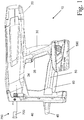
- Fig. 1 shows a driving-in device 10 for driving a fastener, such as a nail or bolt, into a ground in a side view.
- the driving-in device 10 has an energy transmission element (not shown) for transmitting energy to the fastening element and a housing 20, in which the energy transmission element and a likewise not shown drive device for conveying the energy transmission element are accommodated.
- the driving-in device 10 furthermore has a handle 30, a magazine 40 and a bridge 50 connecting the handle 30 to the magazine 40.
- the magazine is not removable. Attached to the bridge 50 are a scaffold hook 60 for suspending the driving-in device 10 on a scaffold or the like, and an electrical energy store designed as a battery 590.
- a trigger 34 and designed as a hand switch 35 Grifflagler are arranged.
- the driving-in device 10 has a guide channel 700 for guiding the fastening element and a pressing device 750 for detecting a distance of the driving-in device 10 from a substrate, not shown. Aligning the driving device perpendicular to a substrate is supported by an alignment aid 45.
- Fig. 2 shows the driving device 10 with the housing 20 open.
- a drive device 70 for carrying a hidden in the drawing energy transfer element is added.
- the drive device 70 comprises an electric motor, not shown, for converting electrical energy from the battery 590 into rotational energy, a transmission 400 comprising a torque transfer device for transmitting a torque of the electric motor to a trained as a spindle drive motion converter 300, a roller train 260 comprehensive power transmission device for transmitting a force from the motion converter to a mechanical energy accumulator designed as a spring 200 and for transmitting a force from the spring to the energy transmission element.
- Fig. 3 shows an electric motor 480 with a motor output 490 in a longitudinal section.
- the motor 480 is configured as a brushless DC motor and has motor coils 495 for driving the motor output 490, which comprises a permanent magnet 491.
- the motor 480 is held by a motor holder, not shown, and supplied by means of the crimp contacts 506 with electrical energy and controlled by the control line 505.
- a motor-side rotary element designed as a motor pinion 410 is fixed against rotation by a press fit.
- the rotating element is cohesively, in particular by gluing or spraying, or positively secured.
- the motor pinion 410 is driven by the motor output 490 and in turn drives a not shown Torque transmission device on.
- a holding device 450 is rotatably mounted on the one hand by means of a bearing 452 on the motor output 490 and on the other hand by means of an annular mounting member 470 rotatably connected to the motor housing. Between the holding device 450 and the mounting member 470, a likewise annular sealing element 460 is arranged, which serves the seal against dust and the like. Together with the line seal 570, the motor housing 24 is sealed from the rest of the housing, wherein the fan 565 sucks air through the ventilation slots 33 for cooling the motor 480 and the remaining drive device is protected from dust.
- the holding device 450 has a magnetic coil 455, which exerts an attraction force on one or more magnet armatures 456 when energized.
- the armature 456 extend in trained as openings anchor recesses 457 of the motor pinion 410 and are thus rotationally fixed to the motor pinion 410 and thus arranged on the motor output 490. Due to the attraction, the armature 456 are pressed against the holding device 450, so that a rotational movement of the motor output 490 is braked or prevented relative to the motor housing.
- FIG. 12 shows another example of a drive-in device 800 having a motor 810 and a support structure 820, which is part of a housing of the drive-in device 800 and supports the motor 810, which is held on the support structure 820 by means of two damping elements 830 designed as ring elements.
- the damping elements 830 each span the motor 810 in a plane extending perpendicular to the drive-in direction of the driving-in device.
- the motor 810 is motion decoupled in all directions relative to the support structure 820.
- the damping elements 830 are made of an elastomer and are annular. They have a circular cross-section and are formed as O-rings.
- Fig. 5 shows a sectional view of the arrangement Fig. 4
- the support structure 820 has grooves 840 for partially receiving a respective damping element 830, wherein each groove 840 in the circumferential direction of the respective damping element 830 is formed completely circumferentially.
- the motor 810 has two grooves 850 for partially receiving a respective damping element 830, wherein each groove 850 is formed completely circumferentially in the circumferential direction of the respective damping element 830.
- Fig. 6 11 shows another example of a driving device 900 with a motor 910 and a support structure 920, which is part of a housing of the driving device 900 and supports the motor 910, which is held on the support structure 920 by means of two damping elements 930 designed as ring elements.
- the damping elements 930 each span the motor 910 in a plane extending perpendicular to the drive-in direction of the drive-in device.
- the damping elements 830 are made of an elastomer and are annular. They have a circular cross-section and are formed as O-rings.
- the driver 900 To cool the engine 910, which is a source of heat, the driver 900 has a fan 960 powered by the same power source as the motor 910, which is supported on the support structure 920 by a fan dam 970.
- the fan is held by means of the Lviderdämpfelements to the engine and thus additionally damped by means of the damping elements of the engine.
- the L intendederdämpfelement 970 is made of an elastomer and forms a housing of the fan 960 and has a preferably T-shaped projection 980, which is accommodated in a receptacle 990 of the support structure 920.
- the projection 980 engages in an undercut of the recording.
Landscapes
- Engineering & Computer Science (AREA)
- Mechanical Engineering (AREA)
- Portable Nailing Machines And Staplers (AREA)
Priority Applications (2)
| Application Number | Priority Date | Filing Date | Title |
|---|---|---|---|
| EP17209518.4A EP3501751A1 (fr) | 2017-12-21 | 2017-12-21 | Dispositif d'enfoncement |
| PCT/EP2018/083712 WO2019121027A1 (fr) | 2017-12-21 | 2018-12-06 | Dispositif d'enfoncement |
Applications Claiming Priority (1)
| Application Number | Priority Date | Filing Date | Title |
|---|---|---|---|
| EP17209518.4A EP3501751A1 (fr) | 2017-12-21 | 2017-12-21 | Dispositif d'enfoncement |
Publications (1)
| Publication Number | Publication Date |
|---|---|
| EP3501751A1 true EP3501751A1 (fr) | 2019-06-26 |
Family
ID=60781859
Family Applications (1)
| Application Number | Title | Priority Date | Filing Date |
|---|---|---|---|
| EP17209518.4A Withdrawn EP3501751A1 (fr) | 2017-12-21 | 2017-12-21 | Dispositif d'enfoncement |
Country Status (2)
| Country | Link |
|---|---|
| EP (1) | EP3501751A1 (fr) |
| WO (1) | WO2019121027A1 (fr) |
Citations (4)
| Publication number | Priority date | Publication date | Assignee | Title |
|---|---|---|---|---|
| US20090236387A1 (en) * | 2005-05-12 | 2009-09-24 | Stanley Fastening Systems, L.P. | Fastener driving device |
| EP2397270A2 (fr) * | 2010-06-15 | 2011-12-21 | HILTI Aktiengesellschaft | outil d'enfoncement d'éléments de fixation |
| EP2881222A1 (fr) * | 2013-12-04 | 2015-06-10 | HILTI Aktiengesellschaft | Dispositif d'entraînement |
| US20160023342A1 (en) * | 2014-07-28 | 2016-01-28 | Black & Decker Inc. | Sound damping for power tools |
-
2017
- 2017-12-21 EP EP17209518.4A patent/EP3501751A1/fr not_active Withdrawn
-
2018
- 2018-12-06 WO PCT/EP2018/083712 patent/WO2019121027A1/fr active Application Filing
Patent Citations (4)
| Publication number | Priority date | Publication date | Assignee | Title |
|---|---|---|---|---|
| US20090236387A1 (en) * | 2005-05-12 | 2009-09-24 | Stanley Fastening Systems, L.P. | Fastener driving device |
| EP2397270A2 (fr) * | 2010-06-15 | 2011-12-21 | HILTI Aktiengesellschaft | outil d'enfoncement d'éléments de fixation |
| EP2881222A1 (fr) * | 2013-12-04 | 2015-06-10 | HILTI Aktiengesellschaft | Dispositif d'entraînement |
| US20160023342A1 (en) * | 2014-07-28 | 2016-01-28 | Black & Decker Inc. | Sound damping for power tools |
Also Published As
| Publication number | Publication date |
|---|---|
| WO2019121027A1 (fr) | 2019-06-27 |
Similar Documents
| Publication | Publication Date | Title |
|---|---|---|
| DE102006038576B4 (de) | Hochpoliger, permanentmagneterregter Synchronmotor mit transversaler Flussführung, hohem Drehmoment und kleiner Drehmassenträgheit | |
| DE102016224265A1 (de) | Elektromotor | |
| EP3727763B1 (fr) | Dispositif d'enfoncement | |
| DE102016224245A1 (de) | Handwerkzeugmaschine mit einem Feder-Rastwerk | |
| DE2031834A1 (de) | Elektromotorischer Regel- und Steuerantrieb mit eingebauter elektromagnetischer Scheibenkupplung und Bremse | |
| DE102013000416A1 (de) | Verfahren zur Anordnung einer Antriebseinheit in einer Karusselltür | |
| EP1662637A2 (fr) | Machine électrique, en particulier motor brushless, et procédé d'ajustement d'une unité de détection dans une machine électrique | |
| WO2019121027A1 (fr) | Dispositif d'enfoncement | |
| EP2607022A2 (fr) | Outil d'enfoncement | |
| DE102010030057A1 (de) | Elektrisch betätigbares Bolzensetzgerät | |
| DE102012208890A1 (de) | Handwerkzeugmaschine | |
| EP2607023A2 (fr) | Outil d'enfoncement | |
| WO2019030031A1 (fr) | Dispositif d'enfoncement et procédé pour utiliser un dispositif d'enfoncement | |
| DE102018216702A1 (de) | Verfahren zur Steuerung oder Regelung einer Handwerkzeugmaschine | |
| WO2019121016A1 (fr) | Dispositif d'enfoncement | |
| EP2794138A2 (fr) | Dispositif d'enfoncement | |
| DE202016103204U1 (de) | Bürstenloser Gleichstrommotor | |
| EP3898111B1 (fr) | Dispositif d'enfoncement | |
| DE202013006345U1 (de) | Schwingungserzeuger | |
| CN215316094U (zh) | 弹簧机倒角装置 | |
| DE1291824B (de) | Einseitig befestigter kleiner Elektromotor mit Aussenlaeufer | |
| EP2532075B1 (fr) | Corps exterieur d'un convertisseur d'énergie électromécanique | |
| DE4405367A1 (de) | Elektromotor, insbesondere Kommutatormotor | |
| EP3323563A1 (fr) | Appareil de pose entraîné par volant d'inertie | |
| DE102013011777A1 (de) | Schwingungserzeuger |
Legal Events
| Date | Code | Title | Description |
|---|---|---|---|
| PUAI | Public reference made under article 153(3) epc to a published international application that has entered the european phase |
Free format text: ORIGINAL CODE: 0009012 |
|
| AK | Designated contracting states |
Kind code of ref document: A1 Designated state(s): AL AT BE BG CH CY CZ DE DK EE ES FI FR GB GR HR HU IE IS IT LI LT LU LV MC MK MT NL NO PL PT RO RS SE SI SK SM TR |
|
| AX | Request for extension of the european patent |
Extension state: BA ME |
|
| STAA | Information on the status of an ep patent application or granted ep patent |
Free format text: STATUS: THE APPLICATION IS DEEMED TO BE WITHDRAWN |
|
| 18D | Application deemed to be withdrawn |
Effective date: 20200103 |