EP3501621A1 - Absorption rotor, rotor element, absorption rotor manufacturing method, and rotor element manufacturing method - Google Patents
Absorption rotor, rotor element, absorption rotor manufacturing method, and rotor element manufacturing method Download PDFInfo
- Publication number
- EP3501621A1 EP3501621A1 EP16885454.5A EP16885454A EP3501621A1 EP 3501621 A1 EP3501621 A1 EP 3501621A1 EP 16885454 A EP16885454 A EP 16885454A EP 3501621 A1 EP3501621 A1 EP 3501621A1
- Authority
- EP
- European Patent Office
- Prior art keywords
- absorption
- drop
- rotor
- plate
- absorption member
- Prior art date
- Legal status (The legal status is an assumption and is not a legal conclusion. Google has not performed a legal analysis and makes no representation as to the accuracy of the status listed.)
- Granted
Links
Images




Classifications
-
- B—PERFORMING OPERATIONS; TRANSPORTING
- B01—PHYSICAL OR CHEMICAL PROCESSES OR APPARATUS IN GENERAL
- B01D—SEPARATION
- B01D53/00—Separation of gases or vapours; Recovering vapours of volatile solvents from gases; Chemical or biological purification of waste gases, e.g. engine exhaust gases, smoke, fumes, flue gases, aerosols
- B01D53/02—Separation of gases or vapours; Recovering vapours of volatile solvents from gases; Chemical or biological purification of waste gases, e.g. engine exhaust gases, smoke, fumes, flue gases, aerosols by adsorption, e.g. preparative gas chromatography
- B01D53/04—Separation of gases or vapours; Recovering vapours of volatile solvents from gases; Chemical or biological purification of waste gases, e.g. engine exhaust gases, smoke, fumes, flue gases, aerosols by adsorption, e.g. preparative gas chromatography with stationary adsorbents
- B01D53/0407—Constructional details of adsorbing systems
-
- B—PERFORMING OPERATIONS; TRANSPORTING
- B01—PHYSICAL OR CHEMICAL PROCESSES OR APPARATUS IN GENERAL
- B01D—SEPARATION
- B01D53/00—Separation of gases or vapours; Recovering vapours of volatile solvents from gases; Chemical or biological purification of waste gases, e.g. engine exhaust gases, smoke, fumes, flue gases, aerosols
- B01D53/02—Separation of gases or vapours; Recovering vapours of volatile solvents from gases; Chemical or biological purification of waste gases, e.g. engine exhaust gases, smoke, fumes, flue gases, aerosols by adsorption, e.g. preparative gas chromatography
- B01D53/06—Separation of gases or vapours; Recovering vapours of volatile solvents from gases; Chemical or biological purification of waste gases, e.g. engine exhaust gases, smoke, fumes, flue gases, aerosols by adsorption, e.g. preparative gas chromatography with moving adsorbents, e.g. rotating beds
-
- B—PERFORMING OPERATIONS; TRANSPORTING
- B01—PHYSICAL OR CHEMICAL PROCESSES OR APPARATUS IN GENERAL
- B01D—SEPARATION
- B01D2253/00—Adsorbents used in seperation treatment of gases and vapours
- B01D2253/10—Inorganic adsorbents
- B01D2253/102—Carbon
-
- B—PERFORMING OPERATIONS; TRANSPORTING
- B01—PHYSICAL OR CHEMICAL PROCESSES OR APPARATUS IN GENERAL
- B01D—SEPARATION
- B01D2253/00—Adsorbents used in seperation treatment of gases and vapours
- B01D2253/10—Inorganic adsorbents
- B01D2253/106—Silica or silicates
- B01D2253/108—Zeolites
-
- B—PERFORMING OPERATIONS; TRANSPORTING
- B01—PHYSICAL OR CHEMICAL PROCESSES OR APPARATUS IN GENERAL
- B01D—SEPARATION
- B01D2257/00—Components to be removed
- B01D2257/70—Organic compounds not provided for in groups B01D2257/00 - B01D2257/602
- B01D2257/708—Volatile organic compounds V.O.C.'s
Definitions
- the present invention relates to an absorption rotor arranged in a flow passage of a gas containing a substance to be absorbed, the absorption rotor that absorbs the substance to be absorbed when the gas passes through, a rotor element, a method of manufacturing an absorption rotor, and a method of manufacturing a rotor element.
- the absorption rotor described in Patent Literature 1 includes a honeycomb body (absorption member) placed between a boss positioned in a center portion and spokes extending from the boss to an outer circumferential ring, the honeycomb body that absorbs a VOC.
- a honeycomb body absorption member
- the honeycomb body absorbs a VOC.
- the spoke and the honeycomb body are adhered to each other via a caulking material.
- the gas passing through the absorption rotor at the time of absorbing and detaching the VOC has a high temperature, there is a fear that adhesion between the spoke and the honeycomb body is removed upon continuous usage.
- the honeycomb body could be dropped off when the absorption rotor is rotated.
- an edge portion of an end surface (surface through which the gas passes) of the honeycomb body and the spoke are fixed by a metal fitting or the like.
- the end surface of the honeycomb body is a flow passage of the gas.
- the honeycomb body may be buckled by the metal fitting due to an influence of wind pressure, so that the honeycomb body may be damaged.
- a problem to tackle is to prevent the honeycomb body from dropping off the absorption rotor without damaging the honeycomb body (absorption member).
- the present invention is achieved to address the above problem, and an object thereof is to provide an absorption rotor capable of preventing an absorption member from dropping off while reducing damage to the absorption member, a rotor element, a method of manufacturing an absorption rotor, and a method of manufacturing a rotor element.
- an absorption rotor being provided in a flow passage of a gas containing a substance to be absorbed, the absorption rotor through which the gas passes while the absorption rotor is rotated about the rotation axis, the absorption rotor including plural plate members extending in a radial manner from the circumference of the rotation axis, a tubular outer edge member coupling end portions of the plural plate members, an absorption member accommodated in a space which is surrounded by the plural plate members and the outer edge member, the absorption member that absorbs the substance to be absorbed when the gas passes through, and a drop-off prevention member respectively fixed to the plate member and the absorption member, the drop-off prevention member that prevents the absorption member from dropping off the plate member, wherein the drop-off prevention member is arranged between the absorption member and the plate member, and between a surface from which the gas flows into the absorption member and a surface from which the gas flows out of the absorption member
- the absorption member can be prevented from dropping off the plate member.
- the drop-off prevention member is not attached to the surfaces through which the gas passes in the absorption member.
- the absorption member is not buckled by the drop-off prevention member due to wind pressure.
- the absorption member can be prevented from dropping off while reducing damage to the absorption member.
- the drop-off prevention member is provided at a position not exposed to the exterior.
- a design property of the absorption rotor becomes favorable.
- the drop-off prevention member may have an embedded portion embedded in the absorption member, and an exposed portion exposed from the absorption member, and the embedded portion may be fixed to the absorption member, and the exposed portion may be fixed to the plate member.
- the plate member and the drop-off prevention member may be respectively made of metal, and an outer end portion of the exposed portion on the side close to the outer edge member and the end portion of the plate member may be welded to each other.
- a hole from which the outer end portion of the drop-off prevention member and the end portion of the plate member are exposed may be formed in the outer edge member.
- the drop-off prevention member and the plate member can be welded from the outside of the outer edge member. Thereby, a working property in assembling of the absorption rotor can be improved.
- the exposed portion may be a flat plate extending from the vicinity of the center portion toward the outer edge member, and the embedded portion may have plural extending portions extending substantially perpendicularly from the exposed portion toward the absorption member.
- the drop-off prevention member can be strongly fixed to the absorption member.
- the plate member may have a holding portion that holds an inner end portion of the exposed portion on the side close to the center portion.
- the holding portion may be formed by two metal blocks provided on a surface of the plate member facing the absorption member, the metal blocks that nip the inner end portion of the exposed portion.
- the holding portion can function as a guide at the time of attaching the absorption member to which the drop-off prevention member is attached to the plate member.
- the absorption member can be attached to the spoke at the right position.
- the above absorption rotor may include reinforcement members attached to the absorption member at positions across the drop-off prevention member with respect to the flow passage of the gas, the reinforcement members that reinforce fixing of the drop-off prevention member.
- a rotor element being provided in an absorption rotor which is provided in a flow passage of a gas containing a substance to be absorbed, the absorption rotor through which the gas passes while the absorption rotor is rotated about the rotation axis, the rotor element including an absorption member accommodated in a space which is surrounded by plural plate members extending in a radial manner from the circumference of the rotation axis and a tubular outer edge member coupling end portions of the plural plate members, the absorption member that absorbs the substance to be absorbed when the gas passes through, and a drop-off prevention member respectively fixed to the plate member and the absorption member, the drop-off prevention member that prevents the absorption member from dropping off the plate member, wherein the drop-off prevention member is arranged between the absorption member and the plate member, and between a surface from which the gas flows into the absorption member and a surface from which the gas flows out of the absorption member.
- a method of manufacturing an absorption rotor according to the present invention is a method of manufacturing an absorption rotor including plural plate members extending in a radial manner from the circumference of the rotation axis, a tubular outer edge member coupling end portions of the plural plate members, an absorption member accommodated in a space which is surrounded by the plural plate members and the outer edge member, the absorption member that absorbs a substance to be absorbed when a gas containing the substance to be absorbed passes through, and a drop-off prevention member respectively fixed to the plate member and the absorption member, the drop-off prevention member that prevents the absorption member from dropping off the plate member, the method including the step of arranging the drop-off prevention member between the absorption member and the plate member, and between a surface from which the gas flows into the absorption member and a surface from which the gas flows out of the absorption member.
- a method of manufacturing a rotor element according to the present invention is a method of manufacturing a rotor element including an absorption member accommodated in a space which is surrounded by plural plate members extending in a radial manner from the circumference of the rotation axis and a tubular outer edge member coupling end portions of the plural plate members, the absorption member that absorbs a substance to be absorbed when a gas containing the substance to be absorbed passes through, and a drop-off prevention member respectively fixed to the plate member and the absorption member, the drop-off prevention member that prevents the absorption member from dropping off the plate member, the method including the step of arranging the drop-off prevention member between the absorption member and the plate member, and between a surface from which the gas flows into the absorption member and a surface from which the gas flows out of the absorption member.
- the absorption member can be prevented from dropping off while reducing damage to the absorption member.
- an absorption rotor 1 according to an embodiment of the present invention (hereinafter, referred to as the present embodiment) will be described with reference to FIGS. 1 to 9 .
- the embodiment to be described below does not limit the present invention but only serves one example for facilitating understanding of the present invention. That is, the shape, size, arrangement, and the like of members to be described below can be modified or improved without departing from the gist of the present invention, and the present invention includes equivalents thereof as a matter of course.
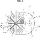
- FIG. 1 is a perspective view of the absorption rotor 1 according to the present embodiment.
- FIG. 2 is an exploded perspective view of a partial configuration of the absorption rotor 1.
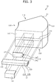
- FIG. 3 is an exploded perspective view of a rotor element 10.
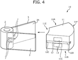
- FIG. 4 is a view for illustrating attachment of the rotor element 10 to a spoke 3.
- FIG. 5 is a view showing a state where the rotor element 10 is attached to the spoke 3.
- FIG. 6 is a sectional view taken along the line VI-VI of FIG. 5 .
- FIG. 7 is an enlarged view of the vicinity of a hole 6 formed in a rim 4.
- the absorption rotor 1 is a device provided in a flow passage of a gas containing a VOC which serves as a substance to be absorbed, for example, the device that absorbs the VOC when the gas passes through the interior of the absorption rotor 1.
- an input gas Ga containing a substance P to be absorbed flows into an inflow surface Fa of the absorption rotor 1.
- the substance P to be absorbed is absorbed.
- an output gas Gb from which the substance P to be absorbed is removed is discharged from an outflow surface Fb.
- the absorption rotor 1 has a hub 2 provided in a center portion, the spokes 3 extending in a radial manner from the hub 2, and the tubular rim 4 coupling end portions of the spokes 3 as frame members.
- an axial hole 2A is formed in a center portion of the hub 2, and an axial member 5 is inserted into the axial hole 2A.
- the absorption rotor 1 can be rotated with the axial member 5 as the rotation axis, and the gas passes through while the absorption rotor is rotated about the axial member 5.
- FIG. 2 shows a state where the rotor element 10 and the axial member 5 are detached from the frame members of the absorption rotor 1.
- the rotor element 10 having a substantially fan-shaped end surface is respectively accommodated.
- the rotor element 10 includes an absorption member 11 that absorbs the substance P to be absorbed, a drop-off prevention member 12, and reinforcement members 13.
- the drop-off prevention member 12 and the reinforcement members 13 are provided on a side surface 11C (surface facing the spoke 3) of the absorption member 11.
- the absorption member 11 is an absorption element of a honeycomb structure, in which the flow passage of the gas is formed in the direction along the axial member 5.
- an absorbent such as activated carbon and hydrophobic zeolite is supported by a honeycomb structure body formed by corrugating an inorganic fabric paper, for example.
- a substantially fan-shaped end surface 11A and an end surface 11B of a back surface thereof in the absorption member 11 serve as surfaces through which the gas passes.
- the drop-off prevention member 12 is a metal member (such as a steel plate) having a substantially U-shaped section and extending substantially from an inner end portion 11E to an outer end portion 11F.
- the drop-off prevention member 12 includes a flat plate-shaped exposed portion 12A placed along the side surface 11C of the absorption member 11, and embedded portions 12B extending from the exposed portion 12A to the side of the absorption member 11.
- the drop-off prevention member 12 is attached to the absorption member 11 as follows, for example. That is, in a state where a caulking material 14A is applied to a surface of the drop-off prevention member 12 on the side facing the absorption member 11, the embedded portions 12B are inserted into slits 11D formed on the side surface 11C of the absorption member 11.
- the slits 11D are formed in a substantially center part of the side surface 11C (specifically, in a substantially center portion in the thickness direction which is orthogonal to the radial direction and the circumferential direction of the substantially fan-shaped absorption member 11 shown in FIG. 3 ) .
- the drop-off prevention member 12 is attached to the substantially center part of the side surface 11C.
- An outer end portion 12D of the drop-off prevention member 12 is attached at the substantially same position as the outer end portion 11F of the absorption member 11.
- the reinforcement member 13 is a metal member having an L-shaped section. Specifically, as shown in FIGS. 3 and 6 , the reinforcement member 13 has a flat plate-shaped exposed portion 13A placed along the side surface 11C of the absorption member 11, and an embedded portion 13B extending from the exposed portion 13A to the side of the absorption member 11.
- the reinforcement member 13 is attached to the absorption member 11 as follows, for example. That is, in a state where an adhesion layer made of the caulking material 14A such as silicon is formed on a surface of the reinforcement member 13 on the side facing the absorption member 11, the embedded portion 13B is inserted at a position adjacent to the embedded portion 12B.
- the insertion position of the embedded portion 13B may be the slit 11D, for example, or may be a slit separately formed at a position adjacent to the slit 11D.
- the reinforcement members 13 are attached on both the sides of the drop-off prevention member 12. By attaching the reinforcement members 13 on both the sides of the drop-off prevention member 12 in such a way, position displacement or warp of the drop-off prevention member 12 is suppressed.
- a side surface on the opposite side of the side surface 11C shown in FIG. 3 has the same configuration.
- FIG. 4 extracts and shows part of the spoke 3. As shown in FIG. 4 , holding portions 7 are formed in a part coupled to the hub 2 on an attachment surface 3A of the spoke 3 to which the rotor element 10 is attached.
- the holding portions 7 are formed by plural nipping bodies that nip an inner end portion 12C, and the above nipping bodies are, for example, blocks made of metal (such as steel plates) .
- the above nipping bodies are, for example, blocks made of metal (such as steel plates) .
- two nipping bodies are attached to the attachment surface 3A of the spoke 3.
- the two nipping bodies are separated from each other so that the drop-off prevention member 12 can be inserted between both the nipping bodies.
- the holding portions 7 may be attached to the attachment surface 3A of the spoke 3 by, for example, welding.
- the above method of welding is not particularly limited but, for example, arc welding, laser welding, and the like can be used.
- the step of attaching the rotor element 10 between the two spokes 3 extending from the hub 2 is as follows, for example. That is, in a state where an adhesion layer made of a caulking material 14B such as silicon is formed on the attachment surface 3A, the rotor element 10 is attached between the two spokes 3 extending from the hub 2. The rotor element 10 is pushed into the spoke 3 in such a manner that the inner end portion 12C of the drop-off prevention member 12 is nipped between the two holding portions 7.
- the absorption rotor 1 is manufactured.
- the rotor element 10 in which the drop-off prevention member 12 is arranged between the absorption member 11 and the spoke 3, and between the end surface 11A from which the gas flows into the absorption member 11 and the end surface 11B from which the gas flows out of the absorption member, and the absorption rotor 1 including such a rotor element 10 can be manufactured.
- FIG. 5 shows a state where the rotor element 10 is attached to the spoke 3.
- the side surface 11C of the rotor element 10 and the attachment surface 3A are adhered to each other via the caulking material 14B. Thereby, in a state where a gap between the rotor element 10 and the spoke 3 is charged with the caulking material 14B, the rotor element 10 is fixed to the spoke 3.
- the gap between the rotor element 10 and the spoke 3 is filled with the caulking material 14B.
- the gas flowing into the absorption rotor 1 can be secured to pass through the absorption member 11.
- both ends of the drop-off prevention member 12 are fixed to the spoke 3.
- the attachment between the rotor element 10 and the spoke 3 can be more strengthened, so that the rotor element 10 is prevented from dropping off the spoke 3.
- the hole 6 may be formed at a position where the spoke 3 and the outer end portion 12D of the drop-off prevention member 12 are abutted with each other.
- the spoke 3 and the outer end portion 12D exposed from the hole 6 may be welded from the exterior of the rim 4.
- a welded portion 15 shown in FIG. 7 shows a welding mark of the outer end portion 12D of the drop-off prevention member 12 and the spoke 3.
- the above method of welding is not particularly limited but, for example, arc welding, laser welding, and the like can be used.
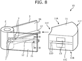
- FIG. 8 is a view for illustrating another example of the attachment of the rotor element to the spoke.
- FIG. 9 is a sectional view taken along the line IX-IX of FIG. 8 in a state where the rotor element is attached to the spoke.
- the drop-off prevention member 12 is attached to the spoke 3 in advance, and then the absorption member 11 is attached to the spoke 3 to which the drop-off prevention member 12 is attached.
- a through hole 21 is formed in a rear end of the spoke 3 which is a part facing the drop-off prevention member 12.
- a through hole is also formed in a part of the drop-off prevention member 12 facing the through hole 21.
- two drop-off prevention members 12 are arranged to face each other across the spoke 3.
- the inner end portion 12C of the drop-off prevention member 12 is nipped by the holding portions 7.
- drop-off prevention members 12 arranged to face each other across the spoke 3, in a state where a bolt 22 is inserted into the through hole 21 via a washer 24, an end portion of the bolt 22 is fastened by a nut 23. Thereby, the drop-off prevention members 12 are fixed to the spoke 3.
- the adhesion layer made of the caulking material such as silicon is formed on the attachment surface 3A of the spoke 3 to which the drop-off prevention member 12 is attached.
- the absorption member 11 to which the reinforcement members 13 are attached is pushed in to the spoke 3 to which the drop-off prevention member 12 is attached, so that the embedded portions 12B of the drop-off prevention member 12 are inserted into the slits 11D of the absorption member 11. In such a way, the rotor element 10 can be attached to the spoke 3.
- the absorption rotor 1 is manufactured.
- the rotor element 10 in which the drop-off prevention member 12 is arranged between the absorption member 11 and the spoke 3, and between the end surface 11A from which the gas flows into the absorption member 11 and the end surface 11B from which the gas flows out of the absorption member, and the absorption rotor 1 including such a rotor element 10 are manufactured.
- the absorption member 11 can be prevented from dropping off the spoke 3.
- the drop-off prevention member 12 is not attached to the end surface 11A and the end surface 11B through which the gas passes in the absorption member 11.
- the absorption member 11 is not buckled by the drop-off prevention member 12 due to wind pressure of the gas.
- the absorption member 11 can be prevented from dropping off while reducing damage to the absorption member 11.
- the drop-off prevention member 12 is provided at a position not exposed to the exterior. Thus, a design property of the absorption rotor becomes favorable.
- welding points for fixing the drop-off prevention member 12 to the spoke 3 may be only the outer end portion 12D of the drop-off prevention member 12 .
- the number of the welding points can be reduced. Thereby, a burden of a welding task at the time of attaching the drop-off prevention member 12 to the spoke 3 can be reduced.
- the hole 6 from which the outer end portion 12D of the drop-off prevention member 12 and the end portion of the spoke 3 are exposed is formed in the rim 4.
- the drop-off prevention member 12 and the spoke 3 can be welded from the outside of the rim 4. Thereby, a working property in assembling of the absorption rotor is improved.
- the drop-off prevention member 12 is formed by a metal member having a substantially U-shaped section, and both the end portions are embedded in the drop-off prevention member 12. Thus, the drop-off prevention member 12 can be strongly fixed to the absorption member 11.
- the spoke 3 With the absorption rotor 1, the spoke 3 includes the holding portions 7 that hold the inner end portion 12C of the drop-off prevention member 12 (exposed portion 12A) on the side close to the hub 2. Thus, the position displacement of the drop-off prevention member 12 can be prevented. Thereby, the drop-off prevention member 12 is not easily dropped off the spoke 3.
- the holding portions 7 function as a guide at the time of attaching the rotor element 10 to the spoke 3.
- the rotor element 10 is easily attached to the spoke 3 at the right position.
- the absorption rotor 1 includes the reinforcement members 13 attached to the absorption member 11 at positions across the drop-off prevention member 12 with respect to the flow passage of the gas. Thus, the position displacement of the drop-off prevention member 12 can be prevented.
- the present invention is not limited to the above embodiment.
- the absorption rotor 1 may be applied to a dehumidifying device, a deodorizing device, and the like.
- the outer end portion 12D of the drop-off prevention member 12 and the spoke 3 are joined to each other by welding.
- the outer end portion and the spoke may be joined mechanically by using bolts, nuts, and the like.
- the number of the reinforcement members 13 may be one, three, or more.
- Arrangement of the reinforcement members 13 is also not limited to the one shown in FIG. 3 and the like.
- right and left positions of the reinforcement members 13 arranged on the upper and lower sides of the drop-off prevention member 12 may be displaced from each other.
- the drop-off prevention member 12 has the exposed portion 12A and the embedded portions 12B.
- the drop-off prevention member 12 may be formed only by an embedded portion 12B. In this case, one end portion of the embedded portion 12B can be fixed to the spoke 3 and the other end portion can be embedded in the absorption member 11.
- the two (two streaks of) embedded portions 12B of the drop-off prevention member 12 are provided.
- one, three, or more (streaks of) embedded portions 12B may be provided.
- the holding portions 7 are formed by the two nipping bodies.
- the holding portions may be formed by three or more nipping bodies.
- the drop-off prevention member 12 is attached to the spoke 3 in advance as in FIGS. 8 and 9 , and then the absorption member 11 (rotor element 10) is attached to the drop-off prevention member 12.
- the present invention is not limited to this.
- the drop-off prevention member 12 may be attached to the absorption member 11 in advance, and then the drop-off prevention member 12 may be attached to the spoke 3.
Landscapes
- Chemical & Material Sciences (AREA)
- Engineering & Computer Science (AREA)
- Analytical Chemistry (AREA)
- General Chemical & Material Sciences (AREA)
- Oil, Petroleum & Natural Gas (AREA)
- Chemical Kinetics & Catalysis (AREA)
- Separation Of Gases By Adsorption (AREA)
- Structures Of Non-Positive Displacement Pumps (AREA)
- Treating Waste Gases (AREA)
Abstract
Description
- The present invention relates to an absorption rotor arranged in a flow passage of a gas containing a substance to be absorbed, the absorption rotor that absorbs the substance to be absorbed when the gas passes through, a rotor element, a method of manufacturing an absorption rotor, and a method of manufacturing a rotor element.
- There is a need for detoxifying a gas containing a VOC (volatile organic compound) which is discharged from various plants such as a printing plant, a painting plant, and a semiconductor plant to discharge to the atmosphere. As a technology to treat such a gas containing a VOC, for example, there is a known system using an absorption rotor described in
Patent Literature 1 below. - The absorption rotor described in
Patent Literature 1 includes a honeycomb body (absorption member) placed between a boss positioned in a center portion and spokes extending from the boss to an outer circumferential ring, the honeycomb body that absorbs a VOC. In the above system, after the VOC is absorbed by letting the gas pass through while the absorption rotor is rotated about the rotation axis, the heated air is blown to a portion onto which the VOC is absorbed, so that the VOC is detached. - PATENT LITERATURE 1:
JP 2004-113844 A - In the above conventional technology, the spoke and the honeycomb body are adhered to each other via a caulking material. However, since the gas passing through the absorption rotor at the time of absorbing and detaching the VOC has a high temperature, there is a fear that adhesion between the spoke and the honeycomb body is removed upon continuous usage. When the adhesion between the spoke and the honeycomb body is removed, the honeycomb body could be dropped off when the absorption rotor is rotated.
- Therefore, in order to prevent the honeycomb body from dropping off, it is thought that an edge portion of an end surface (surface through which the gas passes) of the honeycomb body and the spoke are fixed by a metal fitting or the like. However, the end surface of the honeycomb body is a flow passage of the gas. Thus, the honeycomb body may be buckled by the metal fitting due to an influence of wind pressure, so that the honeycomb body may be damaged.
- In such a way, a problem to tackle is to prevent the honeycomb body from dropping off the absorption rotor without damaging the honeycomb body (absorption member).
- The present invention is achieved to address the above problem, and an object thereof is to provide an absorption rotor capable of preventing an absorption member from dropping off while reducing damage to the absorption member, a rotor element, a method of manufacturing an absorption rotor, and a method of manufacturing a rotor element.
- The above problem is solved by an absorption rotor according to the present invention, the absorption rotor being provided in a flow passage of a gas containing a substance to be absorbed, the absorption rotor through which the gas passes while the absorption rotor is rotated about the rotation axis, the absorption rotor including plural plate members extending in a radial manner from the circumference of the rotation axis, a tubular outer edge member coupling end portions of the plural plate members, an absorption member accommodated in a space which is surrounded by the plural plate members and the outer edge member, the absorption member that absorbs the substance to be absorbed when the gas passes through, and a drop-off prevention member respectively fixed to the plate member and the absorption member, the drop-off prevention member that prevents the absorption member from dropping off the plate member, wherein the drop-off prevention member is arranged between the absorption member and the plate member, and between a surface from which the gas flows into the absorption member and a surface from which the gas flows out of the absorption member.
- With the above absorption rotor, by providing the drop-off prevention member fixed both to the absorption member and the plate member, the absorption member can be prevented from dropping off the plate member.
- With the above absorption rotor, the drop-off prevention member is not attached to the surfaces through which the gas passes in the absorption member. Thus, the absorption member is not buckled by the drop-off prevention member due to wind pressure.
- That is, with the above absorption rotor, the absorption member can be prevented from dropping off while reducing damage to the absorption member.
- With the above absorption rotor, the drop-off prevention member is provided at a position not exposed to the exterior. Thus, a design property of the absorption rotor becomes favorable.
- In the above absorption rotor, the drop-off prevention member may have an embedded portion embedded in the absorption member, and an exposed portion exposed from the absorption member, and the embedded portion may be fixed to the absorption member, and the exposed portion may be fixed to the plate member.
- By doing so, by embedding and attaching part of the drop-off prevention member into the absorption member, attachment of the drop-off prevention member to the absorption member can be strengthened.
- In the above absorption rotor, the plate member and the drop-off prevention member may be respectively made of metal, and an outer end portion of the exposed portion on the side close to the outer edge member and the end portion of the plate member may be welded to each other.
- By doing so, the number of welding points for fixing the drop-off prevention member to the plate member can be reduced. Thereby, a burden of a welding task can be reduced.
- In the above absorption rotor, a hole from which the outer end portion of the drop-off prevention member and the end portion of the plate member are exposed may be formed in the outer edge member.
- By doing so, the drop-off prevention member and the plate member can be welded from the outside of the outer edge member. Thereby, a working property in assembling of the absorption rotor can be improved.
- From the hole formed in the outer edge member, a joining state between the drop-off prevention member and the plate member can be confirmed.
- In the above absorption rotor, the exposed portion may be a flat plate extending from the vicinity of the center portion toward the outer edge member, and the embedded portion may have plural extending portions extending substantially perpendicularly from the exposed portion toward the absorption member.
- By doing so, the drop-off prevention member can be strongly fixed to the absorption member.
- In the above absorption rotor, the plate member may have a holding portion that holds an inner end portion of the exposed portion on the side close to the center portion.
- By doing so, position displacement of the drop-off prevention member can be prevented. Thereby, the drop-off prevention member is not easily dropped off.
- In the above absorption rotor, the holding portion may be formed by two metal blocks provided on a surface of the plate member facing the absorption member, the metal blocks that nip the inner end portion of the exposed portion.
- By doing so, the holding portion can function as a guide at the time of attaching the absorption member to which the drop-off prevention member is attached to the plate member. Thereby, with the above absorption rotor, the absorption member can be attached to the spoke at the right position.
- The above absorption rotor may include reinforcement members attached to the absorption member at positions across the drop-off prevention member with respect to the flow passage of the gas, the reinforcement members that reinforce fixing of the drop-off prevention member.
- By doing so, the position displacement of the drop-off prevention member can be prevented.
- The above problem is solved by a rotor element according to the present invention, the rotor element being provided in an absorption rotor which is provided in a flow passage of a gas containing a substance to be absorbed, the absorption rotor through which the gas passes while the absorption rotor is rotated about the rotation axis, the rotor element including an absorption member accommodated in a space which is surrounded by plural plate members extending in a radial manner from the circumference of the rotation axis and a tubular outer edge member coupling end portions of the plural plate members, the absorption member that absorbs the substance to be absorbed when the gas passes through, and a drop-off prevention member respectively fixed to the plate member and the absorption member, the drop-off prevention member that prevents the absorption member from dropping off the plate member, wherein the drop-off prevention member is arranged between the absorption member and the plate member, and between a surface from which the gas flows into the absorption member and a surface from which the gas flows out of the absorption member.
- A method of manufacturing an absorption rotor according to the present invention is a method of manufacturing an absorption rotor including plural plate members extending in a radial manner from the circumference of the rotation axis, a tubular outer edge member coupling end portions of the plural plate members, an absorption member accommodated in a space which is surrounded by the plural plate members and the outer edge member, the absorption member that absorbs a substance to be absorbed when a gas containing the substance to be absorbed passes through, and a drop-off prevention member respectively fixed to the plate member and the absorption member, the drop-off prevention member that prevents the absorption member from dropping off the plate member, the method including the step of arranging the drop-off prevention member between the absorption member and the plate member, and between a surface from which the gas flows into the absorption member and a surface from which the gas flows out of the absorption member.
- A method of manufacturing a rotor element according to the present invention is a method of manufacturing a rotor element including an absorption member accommodated in a space which is surrounded by plural plate members extending in a radial manner from the circumference of the rotation axis and a tubular outer edge member coupling end portions of the plural plate members, the absorption member that absorbs a substance to be absorbed when a gas containing the substance to be absorbed passes through, and a drop-off prevention member respectively fixed to the plate member and the absorption member, the drop-off prevention member that prevents the absorption member from dropping off the plate member, the method including the step of arranging the drop-off prevention member between the absorption member and the plate member, and between a surface from which the gas flows into the absorption member and a surface from which the gas flows out of the absorption member.
- According to the present invention, the absorption member can be prevented from dropping off while reducing damage to the absorption member.
-
-
FIG. 1 is a perspective view of an absorption rotor according to the present embodiment. -
FIG. 2 is an exploded perspective view of a partial configuration of the absorption rotor. -
FIG. 3 is an exploded perspective view of a rotor element. -
FIG. 4 is a view for illustrating attachment of the rotor element to a spoke. -
FIG. 5 is a view showing a state where the rotor element is attached to the spoke. -
FIG. 6 is a sectional view taken along the line VI-VI ofFIG. 5 . -
FIG. 7 is an enlarged view of the vicinity of a hole formed in a rim. -
FIG. 8 is a view for illustrating another example of the attachment of the rotor element to the spoke. -
FIG. 9 is a sectional view taken along the line IX-IX ofFIG. 8 in a state where the rotor element is attached to the spoke. - Hereinafter, an
absorption rotor 1 according to an embodiment of the present invention (hereinafter, referred to as the present embodiment) will be described with reference toFIGS. 1 to 9 . The embodiment to be described below does not limit the present invention but only serves one example for facilitating understanding of the present invention. That is, the shape, size, arrangement, and the like of members to be described below can be modified or improved without departing from the gist of the present invention, and the present invention includes equivalents thereof as a matter of course. - Firstly, outlines of
FIGS. 1 to 7 will be described.FIG. 1 is a perspective view of theabsorption rotor 1 according to the present embodiment.FIG. 2 is an exploded perspective view of a partial configuration of theabsorption rotor 1.FIG. 3 is an exploded perspective view of arotor element 10.FIG. 4 is a view for illustrating attachment of therotor element 10 to aspoke 3.FIG. 5 is a view showing a state where therotor element 10 is attached to thespoke 3.FIG. 6 is a sectional view taken along the line VI-VI ofFIG. 5 .FIG. 7 is an enlarged view of the vicinity of ahole 6 formed in arim 4. - The
absorption rotor 1 according to the present embodiment is a device provided in a flow passage of a gas containing a VOC which serves as a substance to be absorbed, for example, the device that absorbs the VOC when the gas passes through the interior of theabsorption rotor 1. - That is, as shown in
FIG. 1 , an input gas Ga containing a substance P to be absorbed flows into an inflow surface Fa of theabsorption rotor 1. At the time of passing through theabsorption rotor 1, the substance P to be absorbed is absorbed. In such a way, an output gas Gb from which the substance P to be absorbed is removed is discharged from an outflow surface Fb. Hereinafter, a configuration of theabsorption rotor 1 will be described. - As shown in
FIG. 1 , theabsorption rotor 1 has ahub 2 provided in a center portion, thespokes 3 extending in a radial manner from thehub 2, and thetubular rim 4 coupling end portions of thespokes 3 as frame members. - As shown in
FIGS. 1 and2 , anaxial hole 2A is formed in a center portion of thehub 2, and anaxial member 5 is inserted into theaxial hole 2A. In such a way, theabsorption rotor 1 can be rotated with theaxial member 5 as the rotation axis, and the gas passes through while the absorption rotor is rotated about theaxial member 5. -
FIG. 2 shows a state where therotor element 10 and theaxial member 5 are detached from the frame members of theabsorption rotor 1. - As shown in
FIGS. 1 and2 , in each of spaces surrounded by thespokes 3 and the rim 4 (eight spaces in the present embodiment), therotor element 10 having a substantially fan-shaped end surface is respectively accommodated. - As shown in
FIGS. 2 and3 , therotor element 10 includes anabsorption member 11 that absorbs the substance P to be absorbed, a drop-off prevention member 12, andreinforcement members 13. The drop-off prevention member 12 and thereinforcement members 13 are provided on aside surface 11C (surface facing the spoke 3) of theabsorption member 11. - The
absorption member 11 is an absorption element of a honeycomb structure, in which the flow passage of the gas is formed in the direction along theaxial member 5. In theabsorption member 11, an absorbent such as activated carbon and hydrophobic zeolite is supported by a honeycomb structure body formed by corrugating an inorganic fabric paper, for example. - As shown in
FIG. 3 , a substantially fan-shapedend surface 11A and anend surface 11B of a back surface thereof in theabsorption member 11 serve as surfaces through which the gas passes. - As shown in
FIG. 3 , the drop-off prevention member 12 is a metal member (such as a steel plate) having a substantially U-shaped section and extending substantially from aninner end portion 11E to anouter end portion 11F. - Specifically, as shown in
FIGS. 3 and6 , the drop-off prevention member 12 includes a flat plate-shaped exposedportion 12A placed along theside surface 11C of theabsorption member 11, and embeddedportions 12B extending from the exposedportion 12A to the side of theabsorption member 11. - The drop-
off prevention member 12 is attached to theabsorption member 11 as follows, for example. That is, in a state where acaulking material 14A is applied to a surface of the drop-off prevention member 12 on the side facing theabsorption member 11, the embeddedportions 12B are inserted intoslits 11D formed on theside surface 11C of theabsorption member 11. - The
slits 11D are formed in a substantially center part of theside surface 11C (specifically, in a substantially center portion in the thickness direction which is orthogonal to the radial direction and the circumferential direction of the substantially fan-shapedabsorption member 11 shown inFIG. 3 ) . Thereby, the drop-off prevention member 12 is attached to the substantially center part of theside surface 11C. - An
outer end portion 12D of the drop-off prevention member 12 is attached at the substantially same position as theouter end portion 11F of theabsorption member 11. - As shown in
FIG. 3 , thereinforcement member 13 is a metal member having an L-shaped section. Specifically, as shown inFIGS. 3 and6 , thereinforcement member 13 has a flat plate-shaped exposedportion 13A placed along theside surface 11C of theabsorption member 11, and an embeddedportion 13B extending from the exposedportion 13A to the side of theabsorption member 11. - The
reinforcement member 13 is attached to theabsorption member 11 as follows, for example. That is, in a state where an adhesion layer made of thecaulking material 14A such as silicon is formed on a surface of thereinforcement member 13 on the side facing theabsorption member 11, the embeddedportion 13B is inserted at a position adjacent to the embeddedportion 12B. The insertion position of the embeddedportion 13B may be theslit 11D, for example, or may be a slit separately formed at a position adjacent to theslit 11D. - The
reinforcement members 13 are attached on both the sides of the drop-off prevention member 12. By attaching thereinforcement members 13 on both the sides of the drop-off prevention member 12 in such a way, position displacement or warp of the drop-off prevention member 12 is suppressed. - A side surface on the opposite side of the
side surface 11C shown inFIG. 3 has the same configuration. - Next, the attachment of the
rotor element 10 to thespoke 3 will be described with reference toFIGS. 4 to 6 . -
FIG. 4 extracts and shows part of thespoke 3. As shown inFIG. 4 , holdingportions 7 are formed in a part coupled to thehub 2 on anattachment surface 3A of thespoke 3 to which therotor element 10 is attached. - The holding
portions 7 are formed by plural nipping bodies that nip aninner end portion 12C, and the above nipping bodies are, for example, blocks made of metal (such as steel plates) . In the present embodiment, two nipping bodies are attached to theattachment surface 3A of thespoke 3. The two nipping bodies are separated from each other so that the drop-off prevention member 12 can be inserted between both the nipping bodies. The holdingportions 7 may be attached to theattachment surface 3A of thespoke 3 by, for example, welding. The above method of welding is not particularly limited but, for example, arc welding, laser welding, and the like can be used. - The step of attaching the
rotor element 10 between the twospokes 3 extending from thehub 2 is as follows, for example. That is, in a state where an adhesion layer made of acaulking material 14B such as silicon is formed on theattachment surface 3A, therotor element 10 is attached between the twospokes 3 extending from thehub 2. Therotor element 10 is pushed into thespoke 3 in such a manner that theinner end portion 12C of the drop-off prevention member 12 is nipped between the two holdingportions 7. - By attaching the
rotor element 10 between thespokes 3, theabsorption rotor 1 is manufactured. - By the above step, the
rotor element 10 in which the drop-off prevention member 12 is arranged between theabsorption member 11 and thespoke 3, and between theend surface 11A from which the gas flows into theabsorption member 11 and theend surface 11B from which the gas flows out of the absorption member, and theabsorption rotor 1 including such arotor element 10 can be manufactured. -
FIG. 5 shows a state where therotor element 10 is attached to thespoke 3. Theside surface 11C of therotor element 10 and theattachment surface 3A are adhered to each other via thecaulking material 14B. Thereby, in a state where a gap between therotor element 10 and thespoke 3 is charged with thecaulking material 14B, therotor element 10 is fixed to thespoke 3. - In such a way, the gap between the
rotor element 10 and thespoke 3 is filled with thecaulking material 14B. Thus, the gas flowing into theabsorption rotor 1 can be secured to pass through theabsorption member 11. - In a state where the
inner end portion 12C of the drop-off prevention member 12 provided in therotor element 10 is nipped by the two holdingportions 7 provided in thespoke 3, theouter end portion 12D of the drop-off prevention member 12 is welded to thespoke 3. - Thereby, both ends of the drop-
off prevention member 12 are fixed to thespoke 3. As a result, the attachment between therotor element 10 and thespoke 3 can be more strengthened, so that therotor element 10 is prevented from dropping off thespoke 3. - As shown in
FIGS. 1 and7 , in therim 4, thehole 6 may be formed at a position where thespoke 3 and theouter end portion 12D of the drop-off prevention member 12 are abutted with each other. Thespoke 3 and theouter end portion 12D exposed from thehole 6 may be welded from the exterior of therim 4. - A welded
portion 15 shown inFIG. 7 shows a welding mark of theouter end portion 12D of the drop-off prevention member 12 and thespoke 3. The above method of welding is not particularly limited but, for example, arc welding, laser welding, and the like can be used. - Another example of the attachment of the
rotor element 10 to thespoke 3 will be described with reference toFIGS. 8 and9 . -
FIG. 8 is a view for illustrating another example of the attachment of the rotor element to the spoke.FIG. 9 is a sectional view taken along the line IX-IX ofFIG. 8 in a state where the rotor element is attached to the spoke. - In the example to be described below, the drop-
off prevention member 12 is attached to thespoke 3 in advance, and then theabsorption member 11 is attached to thespoke 3 to which the drop-off prevention member 12 is attached. - As shown in
FIG. 8 , a throughhole 21 is formed in a rear end of thespoke 3 which is a part facing the drop-off prevention member 12. A through hole is also formed in a part of the drop-off prevention member 12 facing the throughhole 21. - As shown in
FIG. 9 , two drop-off prevention members 12 are arranged to face each other across thespoke 3. Theinner end portion 12C of the drop-off prevention member 12 is nipped by the holdingportions 7. - For the drop-
off prevention members 12 arranged to face each other across thespoke 3, in a state where abolt 22 is inserted into the throughhole 21 via awasher 24, an end portion of thebolt 22 is fastened by anut 23. Thereby, the drop-off prevention members 12 are fixed to thespoke 3. - Next, the adhesion layer made of the caulking material such as silicon is formed on the
attachment surface 3A of thespoke 3 to which the drop-off prevention member 12 is attached. Theabsorption member 11 to which thereinforcement members 13 are attached is pushed in to thespoke 3 to which the drop-off prevention member 12 is attached, so that the embeddedportions 12B of the drop-off prevention member 12 are inserted into theslits 11D of theabsorption member 11. In such a way, therotor element 10 can be attached to thespoke 3. - By attaching the
rotor element 10 between thespokes 3, theabsorption rotor 1 is manufactured. - By the above step, the
rotor element 10 in which the drop-off prevention member 12 is arranged between theabsorption member 11 and thespoke 3, and between theend surface 11A from which the gas flows into theabsorption member 11 and theend surface 11B from which the gas flows out of the absorption member, and theabsorption rotor 1 including such arotor element 10 are manufactured. - With the
absorption rotor 1 according to the present embodiment described above, by providing the drop-off prevention member 12 fixed both to theabsorption member 11 and thespoke 3, theabsorption member 11 can be prevented from dropping off thespoke 3. - With the
absorption rotor 1, the drop-off prevention member 12 is not attached to theend surface 11A and theend surface 11B through which the gas passes in theabsorption member 11. Thus, theabsorption member 11 is not buckled by the drop-off prevention member 12 due to wind pressure of the gas. - That is, with the
absorption rotor 1, theabsorption member 11 can be prevented from dropping off while reducing damage to theabsorption member 11. - With the
absorption rotor 1, the drop-off prevention member 12 is provided at a position not exposed to the exterior. Thus, a design property of the absorption rotor becomes favorable. - With the
absorption rotor 1, by embedding and attaching part of the drop-off prevention member 12 into theabsorption member 11, attachment of the drop-off prevention member 12 to theabsorption member 11 can be strengthened. - With the
absorption rotor 1, welding points for fixing the drop-off prevention member 12 to thespoke 3 may be only theouter end portion 12D of the drop-off prevention member 12 . Thus, the number of the welding points can be reduced. Thereby, a burden of a welding task at the time of attaching the drop-off prevention member 12 to thespoke 3 can be reduced. - With the
absorption rotor 1, thehole 6 from which theouter end portion 12D of the drop-off prevention member 12 and the end portion of thespoke 3 are exposed is formed in therim 4. Thus, the drop-off prevention member 12 and thespoke 3 can be welded from the outside of therim 4. Thereby, a working property in assembling of the absorption rotor is improved. - From the
hole 6 formed in therim 4, a joining state between the drop-off prevention member 12 and thespoke 3 can be confirmed. - With the
absorption rotor 1, the drop-off prevention member 12 is formed by a metal member having a substantially U-shaped section, and both the end portions are embedded in the drop-off prevention member 12. Thus, the drop-off prevention member 12 can be strongly fixed to theabsorption member 11. - With the
absorption rotor 1, thespoke 3 includes the holdingportions 7 that hold theinner end portion 12C of the drop-off prevention member 12 (exposedportion 12A) on the side close to thehub 2. Thus, the position displacement of the drop-off prevention member 12 can be prevented. Thereby, the drop-off prevention member 12 is not easily dropped off thespoke 3. - The holding
portions 7 function as a guide at the time of attaching therotor element 10 to thespoke 3. Thus, therotor element 10 is easily attached to thespoke 3 at the right position. - The
absorption rotor 1 includes thereinforcement members 13 attached to theabsorption member 11 at positions across the drop-off prevention member 12 with respect to the flow passage of the gas. Thus, the position displacement of the drop-off prevention member 12 can be prevented. - With the
absorption rotor 1, for therotor element 10 and thespoke 3, two types of joining including the joining using the caulking material and the joining by welding are used. Thus, redundancy of the joining between therotor element 10 and thespoke 3 can be enhanced. Thereby, therotor element 10 is not easily dropped off thespoke 3. - The present invention is not limited to the above embodiment. For example, in the above embodiment, the example in which the
absorption rotor 1 is applied to a VOC treatment device is described. However, theabsorption rotor 1 may be applied to a dehumidifying device, a deodorizing device, and the like. - In the above embodiment, the
outer end portion 12D of the drop-off prevention member 12 and thespoke 3 are joined to each other by welding. However, the outer end portion and the spoke may be joined mechanically by using bolts, nuts, and the like. - In the above embodiment, the example in which the two
reinforcement members 13 are provided for the drop-off prevention member 12 is described. However, the number of thereinforcement members 13 may be one, three, or more. - Arrangement of the
reinforcement members 13 is also not limited to the one shown inFIG. 3 and the like. For example, regarding therotor element 10 shown inFIG. 3 , right and left positions of thereinforcement members 13 arranged on the upper and lower sides of the drop-off prevention member 12 may be displaced from each other. - In the above embodiment, the drop-
off prevention member 12 has the exposedportion 12A and the embeddedportions 12B. However, the drop-off prevention member 12 may be formed only by an embeddedportion 12B. In this case, one end portion of the embeddedportion 12B can be fixed to thespoke 3 and the other end portion can be embedded in theabsorption member 11. - In the above embodiment, the two (two streaks of) embedded
portions 12B of the drop-off prevention member 12 are provided. However, one, three, or more (streaks of) embeddedportions 12B may be provided. - In the above embodiment, the holding
portions 7 are formed by the two nipping bodies. However, the holding portions may be formed by three or more nipping bodies. - In the above embodiment, as one example of the attachment of the
rotor element 10 to thespoke 3, the drop-off prevention member 12 is attached to thespoke 3 in advance as inFIGS. 8 and9 , and then the absorption member 11 (rotor element 10) is attached to the drop-off prevention member 12. However, the present invention is not limited to this. For example, the drop-off prevention member 12 may be attached to theabsorption member 11 in advance, and then the drop-off prevention member 12 may be attached to thespoke 3. In this case, at the time of attaching one drop-off prevention member 12 to thespoke 3, firstly, part of a portion of theabsorption member 11, the portion to which the drop-off prevention member 12 is attached is cut out, and a space for installing any one of a head portion of a bolt and a nut to be screwed onto the leading end side of a threaded portion of the bolt is provided in theabsorption member 11. Then, the head portion of the bolt or the nut is arranged in the space, and the drop-off prevention member 12 and thespoke 3 are fixed by the bolt and the nut. -
- 1:
- Absorption rotor
- 2:
- Hub (center portion)
2A: Axial hole - 3:
- Spoke (plate member)
3A: Attachment surface - 4:
- Rim (outer edge member)
- 5:
- Axial member (rotation axis)
- 6:
- Hole
- 7:
- Holding portion (nipping body)
- 10:
- Rotor element
- 11:
- Absorption member
11A: End surface
11B: End surface
11C: Side surface
11D: Slit
11E: Inner end portion
11F: Outer end portion - 12:
- Drop-off prevention member
12A: Exposed portion
12B: Embedded portion
12C: Inner end portion
12D: Outer end portion - 13:
- Reinforcement member
13A: Exposed portion
13B: Embedded portion
14A: Caulking material
14B: Caulking material - 15:
- Welded portion
- 20:
- Vicinity of hole
- 21:
- Through hole
- 22:
- Bolt
- 23:
- Nut
- 24:
- Washer
- Fa:
- Inflow surface
- Fb:
- Outflow surface
- Ga:
- Input gas
- Gb:
- Output gas
- P:
- Substance to be absorbed
Claims (11)
- An absorption rotor provided in a flow passage of a gas containing a substance to be absorbed, the absorption rotor through which the gas passes while the absorption rotor is rotated about the rotation axis, comprising:plural plate members extending in a radial manner from the circumference of the rotation axis;a tubular outer edge member coupling end portions of the plural plate members;an absorption member accommodated in a space which is surrounded by the plural plate members and the outer edge member, the absorption member that absorbs the substance to be absorbed when the gas passes through; anda drop-off prevention member respectively fixed to the plate member and the absorption member, the drop-off prevention member that prevents the absorption member from dropping off the plate member, whereinthe drop-off prevention member is arranged between the absorption member and the plate member, and between a surface from which the gas flows into the absorption member and a surface from which the gas flows out of the absorption member.
- The absorption rotor according to claim 1, wherein
the drop-off prevention member has an embedded portion embedded in the absorption member, and an exposed portion exposed from the absorption member, and
the embedded portion is fixed to the absorption member, and the exposed portion is fixed to the plate member. - The absorption rotor according to claim 2, wherein
the plate member and the drop-off prevention member are respectively made of metal, and
an outer end portion of the exposed portion on the side close to the outer edge member and the end portion of the plate member are welded to each other. - The absorption rotor according to claim 3, wherein
a hole from which the outer end portion of the drop-off prevention member and the end portion of the plate member are exposed is formed in the outer edge member. - The absorption rotor according to any of claims 2 to 4, wherein
the exposed portion is a flat plate extending from the vicinity of the rotation axis toward the outer edge member, and
the embedded portion has one or plural extending portions extending substantially perpendicularly from the exposed portion toward the absorption member. - The absorption rotor according to any of claims 2 to 5, wherein
the plate member has a holding portion that holds an inner end portion of the exposed portion on the side close to the rotation axis. - The absorption rotor according to claim 6, wherein
the holding portion is formed by plural nipping bodies provided on a surface of the plate member facing the absorption member, the nipping bodies that nip the inner end portion of the exposed portion. - The absorption rotor according to any of claims 1 to 7, comprising:
reinforcement members attached to the absorption member at positions across the drop-off prevention member with respect to the flow passage of the gas, the reinforcement members that reinforce fixing of the drop-off prevention member. - A rotor element provided in an absorption rotor which is provided in a flow passage of a gas containing a substance to be absorbed, the absorption rotor through which the gas passes while the absorption rotor is rotated about the rotation axis, the rotor element comprising:an absorption member accommodated in a space which is surrounded by plural plate members extending in a radial manner from the circumference of the rotation axis and a tubular outer edge member coupling end portions of the plural plate members, the absorption member that absorbs the substance to be absorbed when the gas passes through; anda drop-off prevention member respectively fixed to the plate member and the absorption member, the drop-off prevention member that prevents the absorption member from dropping off the plate member, whereinthe drop-off prevention member is arranged between the absorption member and the plate member, and between a surface from which the gas flows into the absorption member and a surface from which the gas flows out of the absorption member.
- A method of manufacturing an absorption rotor including plural plate members extending in a radial manner from the circumference of the rotation axis, a tubular outer edge member coupling end portions of the plural plate members, an absorption member accommodated in a space which is surrounded by the plural plate members and the outer edge member, the absorption member that absorbs a substance to be absorbed when a gas containing the substance to be absorbed passes through, and a drop-off prevention member respectively fixed to the plate member and the absorption member, the drop-off prevention member that prevents the absorption member from dropping off the plate member,
the method comprising the step of:
arranging the drop-off prevention member between the absorption member and the plate member, and between a surface from which the gas flows into the absorption member and a surface from which the gas flows out of the absorption member. - A method of manufacturing a rotor element including an absorption member accommodated in a space which is surrounded by plural plate members extending in a radial manner from the circumference of the rotation axis and a tubular outer edge member coupling end portions of the plural plate members, the absorption member that absorbs a substance to be absorbed when a gas containing the substance to be absorbed passes through, and a drop-off prevention member respectively fixed to the plate member and the absorption member, the drop-off prevention member that prevents the absorption member from dropping off the plate member,
the method comprising the step of:
arranging the drop-off prevention member between the absorption member and the plate member, and between a surface from which the gas flows into the absorption member and a surface from which the gas flows out of the absorption member.
Applications Claiming Priority (1)
| Application Number | Priority Date | Filing Date | Title |
|---|---|---|---|
| PCT/JP2016/073989 WO2018033971A1 (en) | 2016-08-17 | 2016-08-17 | Absorption rotor, rotor element, absorption rotor manufacturing method, and rotor element manufacturing method |
Publications (3)
| Publication Number | Publication Date |
|---|---|
| EP3501621A1 true EP3501621A1 (en) | 2019-06-26 |
| EP3501621A4 EP3501621A4 (en) | 2020-05-27 |
| EP3501621B1 EP3501621B1 (en) | 2021-07-14 |
Family
ID=61196536
Family Applications (1)
| Application Number | Title | Priority Date | Filing Date |
|---|---|---|---|
| EP16885454.5A Active EP3501621B1 (en) | 2016-08-17 | 2016-08-17 | Absorption rotor and absorption rotor manufacturing method |
Country Status (7)
| Country | Link |
|---|---|
| US (1) | US11027233B2 (en) |
| EP (1) | EP3501621B1 (en) |
| JP (1) | JP6408162B2 (en) |
| KR (1) | KR101948458B1 (en) |
| CN (1) | CN108136315A (en) |
| TW (1) | TWI642470B (en) |
| WO (1) | WO2018033971A1 (en) |
Families Citing this family (1)
| Publication number | Priority date | Publication date | Assignee | Title |
|---|---|---|---|---|
| US12691405B2 (en) | 2023-04-12 | 2026-07-28 | Howden Group Limited | Rotary adsorption machine and a housing therefor |
Family Cites Families (14)
| Publication number | Priority date | Publication date | Assignee | Title |
|---|---|---|---|---|
| GB682278A (en) * | 1949-07-05 | 1952-11-05 | David Dalin | Improvements in regenerative type heat exchangers |
| US3789916A (en) * | 1971-04-06 | 1974-02-05 | Munters Ab Carl | Rotor for exchangers of the thermodynamic characteristics of two gas currents |
| US5057128A (en) * | 1990-07-03 | 1991-10-15 | Flakt, Inc. | Rotary adsorption assembly |
| US5595238A (en) | 1994-09-16 | 1997-01-21 | Engelhard/Icc | Rotatably supported regenerative fluid treatment wheel assemblies |
| CA2316827C (en) * | 1998-01-06 | 2005-11-08 | Donald F. Steele | Rotary heat exchange wheel |
| EP1547666B1 (en) * | 2000-03-30 | 2011-10-19 | Nichias Corporation | A rotor for a rotary adsorber |
| JP3948248B2 (en) * | 2001-10-29 | 2007-07-25 | ダイキン工業株式会社 | Adsorption rotor and adsorption apparatus using the same |
| JP3482409B1 (en) * | 2002-05-30 | 2003-12-22 | 東京エレクトロン株式会社 | Dehumidifying device and method |
| JP2004025132A (en) | 2002-06-28 | 2004-01-29 | Seibu Giken Co Ltd | Adsorption rotor |
| JP3818508B2 (en) | 2002-09-24 | 2006-09-06 | 株式会社西部技研 | Honeycomb adsorption rotor |
| CN104067005B (en) * | 2011-12-15 | 2016-01-20 | 佛吉亚内部系统印度私人有限公司 | Form the assembly of a part for vehicle and be used for the method for the element producing this assembly |
| JP5826627B2 (en) | 2011-12-27 | 2015-12-02 | 株式会社西部技研 | Adsorption rotor |
| TWI549739B (en) | 2014-12-12 | 2016-09-21 | 張豐堂 | Rotating wheel, fluid treatment apparatus, method for removing treatment block of the rotating wheel, and method for removing treatment frame of the rotating wheel |
| TWI624297B (en) * | 2016-11-22 | 2018-05-21 | 傑智環境科技股份有限公司 | Rotary Wheel Having Enhanced Structural Strength And Fluid Processing Equipment Including The Same |
-
2016
- 2016-08-17 EP EP16885454.5A patent/EP3501621B1/en active Active
- 2016-08-17 US US15/763,565 patent/US11027233B2/en active Active
- 2016-08-17 KR KR1020177021496A patent/KR101948458B1/en active Active
- 2016-08-17 WO PCT/JP2016/073989 patent/WO2018033971A1/en not_active Ceased
- 2016-08-17 JP JP2017539698A patent/JP6408162B2/en active Active
- 2016-08-17 CN CN201680006704.7A patent/CN108136315A/en active Pending
-
2017
- 2017-07-26 TW TW106125161A patent/TWI642470B/en active
Also Published As
| Publication number | Publication date |
|---|---|
| CN108136315A (en) | 2018-06-08 |
| EP3501621B1 (en) | 2021-07-14 |
| TWI642470B (en) | 2018-12-01 |
| JPWO2018033971A1 (en) | 2018-08-16 |
| TW201806658A (en) | 2018-03-01 |
| WO2018033971A1 (en) | 2018-02-22 |
| US20180264397A1 (en) | 2018-09-20 |
| EP3501621A4 (en) | 2020-05-27 |
| KR101948458B1 (en) | 2019-02-14 |
| US11027233B2 (en) | 2021-06-08 |
| KR20180029947A (en) | 2018-03-21 |
| JP6408162B2 (en) | 2018-10-17 |
Similar Documents
| Publication | Publication Date | Title |
|---|---|---|
| US20090199523A1 (en) | Compressed Air Supply Device | |
| US11027233B2 (en) | Absorption rotor, rotor element, method of manufacturing absorption rotor, and method of manufacturing rotor element | |
| CN102686419A (en) | Electronic unit including electronic module and inflation valve for measuring wheel operating parameters | |
| JP5132585B2 (en) | Bolt fastening method and fastening bolt device used in the method | |
| FI123263B (en) | Fasteners | |
| US9212680B2 (en) | Tie bar for purposes of connecting equipment fitting of an equipment module, in particular an overhead compartment, to a structure fitting of a fuselage cell structure of an aeronautical vehicle | |
| JP6458837B2 (en) | Double paper tube | |
| US9650931B2 (en) | Exhaust gas treatment device and corresponding method for manufacturing same | |
| US10704414B2 (en) | Airfoil containment structure including a notched and tapered inner shell | |
| JP5919115B2 (en) | Liquid control device and mesh assembly applied to liquid control device | |
| JP2010121496A (en) | Supporting structure of exhaust component cover | |
| US20050217113A1 (en) | Wheel bearing on an axle body for vehicles | |
| CA2766070A1 (en) | Arrangement for securing a lining material | |
| WO2015175669A2 (en) | Tire shield mounting system | |
| ES2785403T3 (en) | Key system to ensure correct use of inserts | |
| KR20110048183A (en) | Lamp with photocatalyst cover | |
| CA2793095A1 (en) | Device for aerating a suspension held in a treatment tank | |
| KR20240143819A (en) | Split type adsorption rotor | |
| JP4899995B2 (en) | Wheel protective cover | |
| WO2010144032A1 (en) | Rotor for a rotating heat exchanger and a method for manufacturing such rotor | |
| JP2016070469A (en) | Piping joint cover, piping joint cover mounting method, and splash prevention device of piping joint part | |
| ES2218039T3 (en) | FIXING ELEMENT FOR THE FIXING OF COATING PLATES ON THE INTERNAL WALLS OF THE MOTOR VEHICLES. | |
| JP2007055764A (en) | Tape reel and reinforcement plate for tape reel | |
| JP6672071B2 (en) | Steam valve valve box and method of assembling the same | |
| KR20080079083A (en) | NBC Filter Fixture |
Legal Events
| Date | Code | Title | Description |
|---|---|---|---|
| STAA | Information on the status of an ep patent application or granted ep patent |
Free format text: STATUS: UNKNOWN |
|
| STAA | Information on the status of an ep patent application or granted ep patent |
Free format text: STATUS: THE INTERNATIONAL PUBLICATION HAS BEEN MADE |
|
| PUAI | Public reference made under article 153(3) epc to a published international application that has entered the european phase |
Free format text: ORIGINAL CODE: 0009012 |
|
| STAA | Information on the status of an ep patent application or granted ep patent |
Free format text: STATUS: REQUEST FOR EXAMINATION WAS MADE |
|
| 17P | Request for examination filed |
Effective date: 20170727 |
|
| AK | Designated contracting states |
Kind code of ref document: A1 Designated state(s): AL AT BE BG CH CY CZ DE DK EE ES FI FR GB GR HR HU IE IS IT LI LT LU LV MC MK MT NL NO PL PT RO RS SE SI SK SM TR |
|
| AX | Request for extension of the european patent |
Extension state: BA ME |
|
| DAV | Request for validation of the european patent (deleted) | ||
| DAX | Request for extension of the european patent (deleted) | ||
| A4 | Supplementary search report drawn up and despatched |
Effective date: 20200424 |
|
| RIC1 | Information provided on ipc code assigned before grant |
Ipc: B01D 53/06 20060101AFI20200420BHEP |
|
| GRAP | Despatch of communication of intention to grant a patent |
Free format text: ORIGINAL CODE: EPIDOSNIGR1 |
|
| STAA | Information on the status of an ep patent application or granted ep patent |
Free format text: STATUS: GRANT OF PATENT IS INTENDED |
|
| INTG | Intention to grant announced |
Effective date: 20210129 |
|
| RIN1 | Information on inventor provided before grant (corrected) |
Inventor name: YAMAZAKI, TERUZI Inventor name: YAMASHITA, KATSUHIRO Inventor name: DEGUCHI, TOMOHIRO Inventor name: TSUZAKI, MASAHIRO Inventor name: CHIGIRA, YUSUKE |
|
| GRAS | Grant fee paid |
Free format text: ORIGINAL CODE: EPIDOSNIGR3 |
|
| GRAA | (expected) grant |
Free format text: ORIGINAL CODE: 0009210 |
|
| STAA | Information on the status of an ep patent application or granted ep patent |
Free format text: STATUS: THE PATENT HAS BEEN GRANTED |
|
| AK | Designated contracting states |
Kind code of ref document: B1 Designated state(s): AL AT BE BG CH CY CZ DE DK EE ES FI FR GB GR HR HU IE IS IT LI LT LU LV MC MK MT NL NO PL PT RO RS SE SI SK SM TR |
|
| REG | Reference to a national code |
Ref country code: GB Ref legal event code: FG4D |
|
| REG | Reference to a national code |
Ref country code: IE Ref legal event code: FG4D |
|
| REG | Reference to a national code |
Ref country code: DE Ref legal event code: R096 Ref document number: 602016060768 Country of ref document: DE |
|
| REG | Reference to a national code |
Ref country code: AT Ref legal event code: REF Ref document number: 1410215 Country of ref document: AT Kind code of ref document: T Effective date: 20210815 |
|
| REG | Reference to a national code |
Ref country code: SE Ref legal event code: TRGR |
|
| REG | Reference to a national code |
Ref country code: LT Ref legal event code: MG9D |
|
| REG | Reference to a national code |
Ref country code: NL Ref legal event code: MP Effective date: 20210714 |
|
| REG | Reference to a national code |
Ref country code: AT Ref legal event code: MK05 Ref document number: 1410215 Country of ref document: AT Kind code of ref document: T Effective date: 20210714 |
|
| PG25 | Lapsed in a contracting state [announced via postgrant information from national office to epo] |
Ref country code: LT Free format text: LAPSE BECAUSE OF FAILURE TO SUBMIT A TRANSLATION OF THE DESCRIPTION OR TO PAY THE FEE WITHIN THE PRESCRIBED TIME-LIMIT Effective date: 20210714 Ref country code: AT Free format text: LAPSE BECAUSE OF FAILURE TO SUBMIT A TRANSLATION OF THE DESCRIPTION OR TO PAY THE FEE WITHIN THE PRESCRIBED TIME-LIMIT Effective date: 20210714 Ref country code: BG Free format text: LAPSE BECAUSE OF FAILURE TO SUBMIT A TRANSLATION OF THE DESCRIPTION OR TO PAY THE FEE WITHIN THE PRESCRIBED TIME-LIMIT Effective date: 20211014 Ref country code: NL Free format text: LAPSE BECAUSE OF FAILURE TO SUBMIT A TRANSLATION OF THE DESCRIPTION OR TO PAY THE FEE WITHIN THE PRESCRIBED TIME-LIMIT Effective date: 20210714 Ref country code: PT Free format text: LAPSE BECAUSE OF FAILURE TO SUBMIT A TRANSLATION OF THE DESCRIPTION OR TO PAY THE FEE WITHIN THE PRESCRIBED TIME-LIMIT Effective date: 20211115 Ref country code: NO Free format text: LAPSE BECAUSE OF FAILURE TO SUBMIT A TRANSLATION OF THE DESCRIPTION OR TO PAY THE FEE WITHIN THE PRESCRIBED TIME-LIMIT Effective date: 20211014 Ref country code: HR Free format text: LAPSE BECAUSE OF FAILURE TO SUBMIT A TRANSLATION OF THE DESCRIPTION OR TO PAY THE FEE WITHIN THE PRESCRIBED TIME-LIMIT Effective date: 20210714 Ref country code: FI Free format text: LAPSE BECAUSE OF FAILURE TO SUBMIT A TRANSLATION OF THE DESCRIPTION OR TO PAY THE FEE WITHIN THE PRESCRIBED TIME-LIMIT Effective date: 20210714 Ref country code: ES Free format text: LAPSE BECAUSE OF FAILURE TO SUBMIT A TRANSLATION OF THE DESCRIPTION OR TO PAY THE FEE WITHIN THE PRESCRIBED TIME-LIMIT Effective date: 20210714 Ref country code: RS Free format text: LAPSE BECAUSE OF FAILURE TO SUBMIT A TRANSLATION OF THE DESCRIPTION OR TO PAY THE FEE WITHIN THE PRESCRIBED TIME-LIMIT Effective date: 20210714 |
|
| PG25 | Lapsed in a contracting state [announced via postgrant information from national office to epo] |
Ref country code: PL Free format text: LAPSE BECAUSE OF FAILURE TO SUBMIT A TRANSLATION OF THE DESCRIPTION OR TO PAY THE FEE WITHIN THE PRESCRIBED TIME-LIMIT Effective date: 20210714 Ref country code: LV Free format text: LAPSE BECAUSE OF FAILURE TO SUBMIT A TRANSLATION OF THE DESCRIPTION OR TO PAY THE FEE WITHIN THE PRESCRIBED TIME-LIMIT Effective date: 20210714 Ref country code: GR Free format text: LAPSE BECAUSE OF FAILURE TO SUBMIT A TRANSLATION OF THE DESCRIPTION OR TO PAY THE FEE WITHIN THE PRESCRIBED TIME-LIMIT Effective date: 20211015 |
|
| REG | Reference to a national code |
Ref country code: CH Ref legal event code: PL |
|
| REG | Reference to a national code |
Ref country code: DE Ref legal event code: R097 Ref document number: 602016060768 Country of ref document: DE |
|
| REG | Reference to a national code |
Ref country code: BE Ref legal event code: MM Effective date: 20210831 |
|
| PG25 | Lapsed in a contracting state [announced via postgrant information from national office to epo] |
Ref country code: LI Free format text: LAPSE BECAUSE OF NON-PAYMENT OF DUE FEES Effective date: 20210831 Ref country code: DK Free format text: LAPSE BECAUSE OF FAILURE TO SUBMIT A TRANSLATION OF THE DESCRIPTION OR TO PAY THE FEE WITHIN THE PRESCRIBED TIME-LIMIT Effective date: 20210714 Ref country code: CH Free format text: LAPSE BECAUSE OF NON-PAYMENT OF DUE FEES Effective date: 20210831 |
|
| PLBE | No opposition filed within time limit |
Free format text: ORIGINAL CODE: 0009261 |
|
| STAA | Information on the status of an ep patent application or granted ep patent |
Free format text: STATUS: NO OPPOSITION FILED WITHIN TIME LIMIT |
|
| PG25 | Lapsed in a contracting state [announced via postgrant information from national office to epo] |
Ref country code: SM Free format text: LAPSE BECAUSE OF FAILURE TO SUBMIT A TRANSLATION OF THE DESCRIPTION OR TO PAY THE FEE WITHIN THE PRESCRIBED TIME-LIMIT Effective date: 20210714 Ref country code: SK Free format text: LAPSE BECAUSE OF FAILURE TO SUBMIT A TRANSLATION OF THE DESCRIPTION OR TO PAY THE FEE WITHIN THE PRESCRIBED TIME-LIMIT Effective date: 20210714 Ref country code: RO Free format text: LAPSE BECAUSE OF FAILURE TO SUBMIT A TRANSLATION OF THE DESCRIPTION OR TO PAY THE FEE WITHIN THE PRESCRIBED TIME-LIMIT Effective date: 20210714 Ref country code: MC Free format text: LAPSE BECAUSE OF FAILURE TO SUBMIT A TRANSLATION OF THE DESCRIPTION OR TO PAY THE FEE WITHIN THE PRESCRIBED TIME-LIMIT Effective date: 20210714 Ref country code: LU Free format text: LAPSE BECAUSE OF NON-PAYMENT OF DUE FEES Effective date: 20210817 Ref country code: EE Free format text: LAPSE BECAUSE OF FAILURE TO SUBMIT A TRANSLATION OF THE DESCRIPTION OR TO PAY THE FEE WITHIN THE PRESCRIBED TIME-LIMIT Effective date: 20210714 Ref country code: CZ Free format text: LAPSE BECAUSE OF FAILURE TO SUBMIT A TRANSLATION OF THE DESCRIPTION OR TO PAY THE FEE WITHIN THE PRESCRIBED TIME-LIMIT Effective date: 20210714 Ref country code: AL Free format text: LAPSE BECAUSE OF FAILURE TO SUBMIT A TRANSLATION OF THE DESCRIPTION OR TO PAY THE FEE WITHIN THE PRESCRIBED TIME-LIMIT Effective date: 20210714 |
|
| 26N | No opposition filed |
Effective date: 20220419 |
|
| GBPC | Gb: european patent ceased through non-payment of renewal fee |
Effective date: 20211014 |
|
| PG25 | Lapsed in a contracting state [announced via postgrant information from national office to epo] |
Ref country code: IE Free format text: LAPSE BECAUSE OF NON-PAYMENT OF DUE FEES Effective date: 20210817 Ref country code: GB Free format text: LAPSE BECAUSE OF NON-PAYMENT OF DUE FEES Effective date: 20211014 Ref country code: FR Free format text: LAPSE BECAUSE OF NON-PAYMENT OF DUE FEES Effective date: 20210914 Ref country code: BE Free format text: LAPSE BECAUSE OF NON-PAYMENT OF DUE FEES Effective date: 20210831 |
|
| P01 | Opt-out of the competence of the unified patent court (upc) registered |
Effective date: 20230512 |
|
| PG25 | Lapsed in a contracting state [announced via postgrant information from national office to epo] |
Ref country code: CY Free format text: LAPSE BECAUSE OF FAILURE TO SUBMIT A TRANSLATION OF THE DESCRIPTION OR TO PAY THE FEE WITHIN THE PRESCRIBED TIME-LIMIT Effective date: 20210714 |
|
| PG25 | Lapsed in a contracting state [announced via postgrant information from national office to epo] |
Ref country code: HU Free format text: LAPSE BECAUSE OF FAILURE TO SUBMIT A TRANSLATION OF THE DESCRIPTION OR TO PAY THE FEE WITHIN THE PRESCRIBED TIME-LIMIT; INVALID AB INITIO Effective date: 20160817 |
|
| PG25 | Lapsed in a contracting state [announced via postgrant information from national office to epo] |
Ref country code: MK Free format text: LAPSE BECAUSE OF FAILURE TO SUBMIT A TRANSLATION OF THE DESCRIPTION OR TO PAY THE FEE WITHIN THE PRESCRIBED TIME-LIMIT Effective date: 20210714 |
|
| PG25 | Lapsed in a contracting state [announced via postgrant information from national office to epo] |
Ref country code: MT Free format text: LAPSE BECAUSE OF FAILURE TO SUBMIT A TRANSLATION OF THE DESCRIPTION OR TO PAY THE FEE WITHIN THE PRESCRIBED TIME-LIMIT Effective date: 20210714 |
|
| PGFP | Annual fee paid to national office [announced via postgrant information from national office to epo] |
Ref country code: SE Payment date: 20240702 Year of fee payment: 9 |
|
| PGFP | Annual fee paid to national office [announced via postgrant information from national office to epo] |
Ref country code: DE Payment date: 20250702 Year of fee payment: 10 |
|
| PGFP | Annual fee paid to national office [announced via postgrant information from national office to epo] |
Ref country code: IT Payment date: 20250722 Year of fee payment: 10 |
|
| PG25 | Lapsed in a contracting state [announced via postgrant information from national office to epo] |
Ref country code: TR Free format text: LAPSE BECAUSE OF FAILURE TO SUBMIT A TRANSLATION OF THE DESCRIPTION OR TO PAY THE FEE WITHIN THE PRESCRIBED TIME-LIMIT Effective date: 20210714 |
|
| PG25 | Lapsed in a contracting state [announced via postgrant information from national office to epo] |
Ref country code: SE Free format text: LAPSE BECAUSE OF NON-PAYMENT OF DUE FEES Effective date: 20250818 |