EP3500732B1 - Unité de refoulement - Google Patents
Unité de refoulement Download PDFInfo
- Publication number
- EP3500732B1 EP3500732B1 EP17731127.1A EP17731127A EP3500732B1 EP 3500732 B1 EP3500732 B1 EP 3500732B1 EP 17731127 A EP17731127 A EP 17731127A EP 3500732 B1 EP3500732 B1 EP 3500732B1
- Authority
- EP
- European Patent Office
- Prior art keywords
- drive shaft
- bearing sleeve
- rotor
- delivery unit
- unit according
- Prior art date
- Legal status (The legal status is an assumption and is not a legal conclusion. Google has not performed a legal analysis and makes no representation as to the accuracy of the status listed.)
- Active
Links
- 238000005086 pumping Methods 0.000 title 1
- 229920001187 thermosetting polymer Polymers 0.000 claims description 9
- 238000007789 sealing Methods 0.000 claims description 8
- 229920001169 thermoplastic Polymers 0.000 claims description 7
- 239000004416 thermosoftening plastic Substances 0.000 claims description 7
- 239000004033 plastic Substances 0.000 claims description 4
- 229920003023 plastic Polymers 0.000 claims description 4
- 229910000831 Steel Inorganic materials 0.000 claims 1
- 230000000717 retained effect Effects 0.000 claims 1
- 239000010959 steel Substances 0.000 claims 1
- 239000000565 sealant Substances 0.000 description 4
- 229910001220 stainless steel Inorganic materials 0.000 description 4
- 239000010935 stainless steel Substances 0.000 description 4
- 239000000463 material Substances 0.000 description 3
- 239000012530 fluid Substances 0.000 description 2
- 229920002943 EPDM rubber Polymers 0.000 description 1
- 239000004696 Poly ether ether ketone Substances 0.000 description 1
- XSQUKJJJFZCRTK-UHFFFAOYSA-N Urea Chemical compound NC(N)=O XSQUKJJJFZCRTK-UHFFFAOYSA-N 0.000 description 1
- JUPQTSLXMOCDHR-UHFFFAOYSA-N benzene-1,4-diol;bis(4-fluorophenyl)methanone Chemical compound OC1=CC=C(O)C=C1.C1=CC(F)=CC=C1C(=O)C1=CC=C(F)C=C1 JUPQTSLXMOCDHR-UHFFFAOYSA-N 0.000 description 1
- 239000004202 carbamide Substances 0.000 description 1
- 238000011161 development Methods 0.000 description 1
- 230000018109 developmental process Effects 0.000 description 1
- 229920002457 flexible plastic Polymers 0.000 description 1
- 238000011990 functional testing Methods 0.000 description 1
- 230000001050 lubricating effect Effects 0.000 description 1
- 238000004519 manufacturing process Methods 0.000 description 1
- 239000002184 metal Substances 0.000 description 1
- 229920002530 polyetherether ketone Polymers 0.000 description 1
- 239000004810 polytetrafluoroethylene Substances 0.000 description 1
- 229920001343 polytetrafluoroethylene Polymers 0.000 description 1
- 238000012805 post-processing Methods 0.000 description 1
- 230000000284 resting effect Effects 0.000 description 1
- 238000004804 winding Methods 0.000 description 1
Images


Classifications
-
- F—MECHANICAL ENGINEERING; LIGHTING; HEATING; WEAPONS; BLASTING
- F01—MACHINES OR ENGINES IN GENERAL; ENGINE PLANTS IN GENERAL; STEAM ENGINES
- F01C—ROTARY-PISTON OR OSCILLATING-PISTON MACHINES OR ENGINES
- F01C21/00—Component parts, details or accessories not provided for in groups F01C1/00 - F01C20/00
- F01C21/02—Arrangements of bearings
-
- F—MECHANICAL ENGINEERING; LIGHTING; HEATING; WEAPONS; BLASTING
- F04—POSITIVE - DISPLACEMENT MACHINES FOR LIQUIDS; PUMPS FOR LIQUIDS OR ELASTIC FLUIDS
- F04C—ROTARY-PISTON, OR OSCILLATING-PISTON, POSITIVE-DISPLACEMENT MACHINES FOR LIQUIDS; ROTARY-PISTON, OR OSCILLATING-PISTON, POSITIVE-DISPLACEMENT PUMPS
- F04C11/00—Combinations of two or more machines or pumps, each being of rotary-piston or oscillating-piston type; Pumping installations
- F04C11/008—Enclosed motor pump units
-
- F—MECHANICAL ENGINEERING; LIGHTING; HEATING; WEAPONS; BLASTING
- F04—POSITIVE - DISPLACEMENT MACHINES FOR LIQUIDS; PUMPS FOR LIQUIDS OR ELASTIC FLUIDS
- F04C—ROTARY-PISTON, OR OSCILLATING-PISTON, POSITIVE-DISPLACEMENT MACHINES FOR LIQUIDS; ROTARY-PISTON, OR OSCILLATING-PISTON, POSITIVE-DISPLACEMENT PUMPS
- F04C3/00—Rotary-piston machines or pumps, with non-parallel axes of movement of co-operating members, e.g. of screw type
- F04C3/06—Rotary-piston machines or pumps, with non-parallel axes of movement of co-operating members, e.g. of screw type the axes being arranged otherwise than at an angle of 90 degrees
- F04C3/08—Rotary-piston machines or pumps, with non-parallel axes of movement of co-operating members, e.g. of screw type the axes being arranged otherwise than at an angle of 90 degrees of intermeshing engagement type, i.e. with engagement of co-operating members similar to that of toothed gearing
-
- F—MECHANICAL ENGINEERING; LIGHTING; HEATING; WEAPONS; BLASTING
- F04—POSITIVE - DISPLACEMENT MACHINES FOR LIQUIDS; PUMPS FOR LIQUIDS OR ELASTIC FLUIDS
- F04C—ROTARY-PISTON, OR OSCILLATING-PISTON, POSITIVE-DISPLACEMENT MACHINES FOR LIQUIDS; ROTARY-PISTON, OR OSCILLATING-PISTON, POSITIVE-DISPLACEMENT PUMPS
- F04C2240/00—Components
- F04C2240/40—Electric motor
-
- F—MECHANICAL ENGINEERING; LIGHTING; HEATING; WEAPONS; BLASTING
- F04—POSITIVE - DISPLACEMENT MACHINES FOR LIQUIDS; PUMPS FOR LIQUIDS OR ELASTIC FLUIDS
- F04C—ROTARY-PISTON, OR OSCILLATING-PISTON, POSITIVE-DISPLACEMENT MACHINES FOR LIQUIDS; ROTARY-PISTON, OR OSCILLATING-PISTON, POSITIVE-DISPLACEMENT PUMPS
- F04C2240/00—Components
- F04C2240/50—Bearings
- F04C2240/56—Bearing bushings or details thereof
-
- F—MECHANICAL ENGINEERING; LIGHTING; HEATING; WEAPONS; BLASTING
- F04—POSITIVE - DISPLACEMENT MACHINES FOR LIQUIDS; PUMPS FOR LIQUIDS OR ELASTIC FLUIDS
- F04C—ROTARY-PISTON, OR OSCILLATING-PISTON, POSITIVE-DISPLACEMENT MACHINES FOR LIQUIDS; ROTARY-PISTON, OR OSCILLATING-PISTON, POSITIVE-DISPLACEMENT PUMPS
- F04C2240/00—Components
- F04C2240/60—Shafts
- F04C2240/605—Shaft sleeves or details thereof
Definitions
- the invention relates to a conveyor unit according to the type of the main claim. It is already a conveyor unit from the DE102014209140 A1 known, with a drive shaft and a rotor driven by the drive shaft, rotatably arranged in a pump stator.
- the drive shaft has an inclined sliding plane which interacts with the rotor and causes the rotor with its rotor axis to wobble around a drive axis of the drive shaft.
- the rotor has a toothing on its end facing away from the drive shaft, which meshes with a toothing formed on the pump stator. Working spaces for conveying media are formed between the teeth of the rotor and the teeth of the pump stator.
- the drive shaft, the rotor and the pump stator are individual pump components that work together to achieve certain properties, such as delivery volume, efficiency and pressure build-up, within certain tolerances. Whether the pump components can jointly meet these required properties can only be tested in a functional test on the finished product, i.e. after the delivery unit has been completely assembled.
- the delivery unit according to the invention with the characterizing features of the main claim has the advantage that the drive shaft, the rotor and the pump stator form a pump unit that can be tested for the fulfillment of the necessary properties alone.
- a drive of a test bench is used to drive the pump unit.
- the pump unit is achieved in that the drive shaft is arranged in a bearing sleeve which has a shoulder which projects in the radial direction with respect to the drive axis has, on which the pump stator is held by means of at least one holding means. If the pump unit does not meet the required properties in the function test, the pump unit is improved in a post-processing step. This rectification can take place immediately after the pump unit has been assembled and not only after the pump unit and drive have been assembled, that is, not only after the entire delivery unit has been completed. This reduces manufacturing costs.
- the at least one holding means can advantageously achieve a positive and / or non-positive connection between the shoulder of the bearing sleeve and the pump stator, in particular a snap-in, clamp, press or screw connection.
- the at least one holding means is formed by a deformed ring collar which is provided on the shoulder of the bearing sleeve and engages behind the pump stator.
- the at least one holding means is formed by a holding ring which is arranged on the side of the pump stator facing away from the rotor and engages behind the shoulder of the bearing sleeve with latching means.
- the pump stator can be pressed against the shoulder of the bearing sleeve by a housing of the delivery unit.
- the bearing sleeve is attached to the pump stator in such a way that the bearing sleeve is arranged concentrically to the drive axis of the drive shaft. In this way, an alignment or centering of the components of the pump unit with respect to one another is achieved, so that the radial forces on the rotating components can be reduced and the wear and the reduction in pump efficiency resulting from the internal leakage can be minimized.
- At least one sealant is provided which seals a gap between the bearing sleeve and the drive shaft. In this way, the internal losses between the high-pressure side and the low-pressure side in the form of returning medium to the suction point of the delivery unit are reduced and the pump efficiency is increased.
- the bearing sleeve has three step sections with different diameters, a sliding bearing being provided on each of the two outer step sections and the at least one sealing means being provided on the middle step section. In this way, the tread for the sealant can be produced particularly inexpensively.
- the bearing sleeve is conical, since this simplifies the deep-drawing of the bearing sleeve.
- the drive shaft In order to obtain a constant sealing gap, seen in the axial direction, in spite of the taper of the bearing sleeve, the drive shaft must also be conical in a corresponding manner. Due to the constant sealing gap seen in the axial direction, a good seal is achieved and a hydrodynamic lubricating film is generated.
- the bearing sleeve is made of a stainless steel and the drive shaft, the rotor and the pump stator are made of a plastic, in particular a thermoset. This selection of materials makes the conveyor unit suitable for conveying aqueous urea solutions.
- the drive shaft is coupled to a rotatably mounted magnet armature which surrounds the drive shaft in a ring and is rotatably mounted on the bearing sleeve.
- the bearing sleeve provides a plain bearing for the drive shaft and a plain bearing for the magnet armature.
- the pump stator has an upper layer facing the rotor and a carrier layer facing away from the rotor, the upper layer being made of a thermosetting plastic and the carrier layer being made of a thermoplastic. Due to the more flexible plastic of the carrier layer, the stator can adapt better to the rotor, so that gaps between the teeth of the rotor and pump stator are reduced.
- the drive shaft has an upper layer facing the bearing sleeve and a carrier layer facing away from the bearing sleeve, the The top layer is made of a thermosetting plastic and the backing layer is made of a thermoplastic. In this way, the dimensional accuracy of the drive shaft is improved.
- Fig. 1 shows a sectional view of a delivery unit with a pump unit according to the invention according to a first embodiment.
- the delivery unit according to the invention is used to deliver fluid delivery media.
- the conveyor unit 1 comprises a drive shaft 2 and a rotor 4 driven by the drive shaft 2 and rotatably arranged in a pump stator 3.
- the drive shaft 2, the pump stator 3 and the rotor 4 are made, for example, of a plastic, in particular a thermoset.
- the drive shaft 2 has an inclined sliding plane 5 which interacts with the rotor 4 and causes the rotor 4 with its rotor axis 6 to wobble around a drive axis 7 of the drive shaft 2.
- the inclined sliding plane 5 is provided, for example, on an end face of a shoulder section 10 of the drive shaft 2.
- the rotor 4 has on its end facing away from the drive shaft 2 a toothing 11 which meshes with a toothing 12 formed on the pump stator 3, 3 working spaces for conveying the conveying medium being formed between the toothing 11 of the rotor 4 and the toothing 12 of the pump stator.
- the pump stator 3 can be made of a single material or alternatively can comprise a top layer facing the rotor 4 and a carrier layer facing away from the rotor 4, the top layer being made of a thermosetting plastic and the carrier layer being made of a thermoplastic.
- magnets 14 are provided, by means of which the drive shaft 2 can be driven in cooperation with a magnetic field of an electrical winding 15 of a stator 16.
- the stator 16 is designed, for example, as a stator laminated core.
- the magnets 14 are provided on a magnet armature 17 which is rotatably mounted about the drive axis 7 and which surrounds the drive shaft 2 in a ring shape and is mechanically connected to the drive shaft 2.
- the magnet armature 17 is positively connected to the magnet armature 17, according to the exemplary embodiment via a toothing 18, 19.
- the magnet armature 17 has a through opening 22 for receiving a section of the drive shaft 2.
- the toothing 18 is formed, which interacts mechanically with the toothing 19 of the drive shaft 2.
- the teeth 18, 19 are designed as straight teeth, for example as involute teeth or circular arc teeth.
- the drive shaft 2 can be displaced in the axial direction with respect to the drive axis 7 with respect to the magnet armature 17, so that the weight of the magnets 14 is supported on the bearing sleeve 24 via the support disk 30 and does not act on the drive shaft 2.
- the magnet armature 17 has a magnet carrier 20 holding the magnets 14, which is made of plastic and encloses the magnets 14 in the radial direction on the inside facing the drive shaft 2, in the circumferential direction between the magnets 14 and in the axial direction on the end faces.
- the hollow cylindrical magnet armature 17 is surrounded by the stator 16 and arranged in a first, for example pot-shaped, housing section 23.
- the stator 16 is provided, for example, on the outer circumference of the first housing section 23.
- a bearing sleeve 24 is provided for mounting the drive shaft 2, which extends into the through opening 22 of the magnet armature 17 and in which the drive shaft 2 is rotatably mounted.
- the bearing sleeve 24 is, for example, cylindrical and / or sheet-shaped.
- the section of the drive shaft 2 which is mounted in the bearing sleeve 24 is also cylindrical.
- the Bearing sleeve 24 is slightly conical and the corresponding section of the drive shaft 2 is also conical at the same angle.
- the bearing sleeve 24 is made of a sheet metal, which consists for example of stainless steel.
- the drive shaft 2 projects in the axial direction with respect to the drive axis 7 with the shoulder section 10 from the bearing sleeve 24.
- the drive shaft 2 can be made from a single material or alternatively can have an upper layer facing the bearing sleeve 24 and a carrier layer facing away from the bearing sleeve 24, the top layer being made of a thermosetting plastic and the carrier layer being made of a thermoplastic.
- a bearing ring 25 is fastened to an end face of the magnet armature 17 and has a sleeve section 28 and a disk section 29 which projects in the radial direction with respect to the drive axis 7.
- the sleeve section 28 of the bearing ring 25 is rotatably mounted on the bearing sleeve 24.
- the disk section 29 of the bearing ring 25 forms an axial slide bearing with a support disk 30 resting on the housing section 23.
- the support disk 30 is made of stainless steel, for example, and the bearing ring 25 is made of high-temperature-resistant thermoplastic, in particular PEEK.
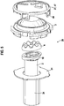
- the drive shaft 2, the pump stator 3, the rotor 4 and the bearing sleeve 24 form a pump unit 26.
- the bearing sleeve 24 has at its end facing the rotor 4 a shoulder 31 which is in the form of an annular disk in the radial direction with respect to the drive axis 7 protrudes and on which the pump stator 3 is held by means of at least one holding means 27.
- the at least one holding means 27 establishes a positive and / or non-positive connection between the shoulder 31 of the bearing sleeve 24 and the pump stator 3, for example a snap, clamp, press or screw connection.
- the at least one holding means 27 is formed by a deformed ring collar 46 which is provided on the shoulder 31 of the bearing sleeve 24 and engages behind the pump stator 3.
- a receiving section 32 for receiving the pump stator 3 is formed by the shoulder 31 and the annular collar 46 of the bearing sleeve 24.
- the bearing sleeve 24 is fastened to the pump stator 3 in such a way that the bearing sleeve 24 is concentric with the drive axis 7 the drive shaft 2 is arranged.
- the pump stator 3 and the receiving section 32 of the bearing sleeve 24 enclose a space in which the shoulder section 10 of the drive shaft 2 and the rotor 4 are arranged.
- the shoulder 31 of the bearing sleeve 24 bears against the support disk 30.
- a second, for example lid-shaped, housing section 34 which closes the first housing section 23, presses the support disk 30 with at least one holding section 36 against a shoulder 35 of the first housing section 23 and the pump stator 3 against the shoulder 31 of the bearing sleeve 24.
- the first housing section 23 and the second housing section 34 together form a housing of the conveying unit 1.
- the second housing section 34 together with the support disk 30 and the receiving section 32 of the bearing sleeve 24, encloses an annular space 37 in which, for example, an annular sealing element 38 is arranged.
- a channel 40 is formed in the drive shaft 2, in which a spring 41 is provided, which is biased at one end by a bearing pin 42 protruding into the channel 40 and presses the drive shaft 2 against the rotor 4 with its other end.
- the bearing pin 42 is fastened, for example, to a bottom 43 of the cup-shaped first housing section 23.
- a ball 44 can be provided, which rotates with the spring 41 and the drive shaft 2 and represents a low-wear connection to the bearing pin 42.
- the channel 40 is, for example, a through-channel extending in the axial direction, which runs from an end facing away from the rotor 4 to the end facing the rotor 4 with the inclined sliding plane 5 and leads fluid on the suction side to the working chambers or discharges it on the pressure side.
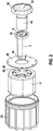
- Fig. 2 shows an exploded view of the conveyor unit after Fig. 1 .
- Fig. 2 shows an exploded view of the conveyor unit after Fig. 1 .
- Fig. 1 parts that remain the same or have the same function are identified by the same reference numerals.
- Fig. 3 shows the pump unit according to the first embodiment.
- Fig. 4 shows a pump unit according to the second embodiment.
- the at least one holding means 27 is designed as a separate retaining ring 47, which is arranged on the side of the pump stator 3 facing away from the rotor 4 and engages behind the shoulder 31 of the bearing sleeve 24 with locking means 48, for example resilient locking arms.
- the retaining ring 47 is made of stainless steel, for example.
- Fig. 5 shows an exploded view of the pump unit according to Fig. 4 .
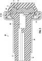
- Fig. 6 shows a pump unit according to a third embodiment.
- At least one sealant 50 is provided on a gap 51 between the bearing sleeve 24 and the drive shaft 2, which seals the gap 51.
- the bearing sleeve 24 has, for example, four step sections 24.1, each with a different diameter.
- a slide bearing is formed on each of the two outer step sections 24.1 of the bearing sleeve 24.
- the at least one sealing means 50 is provided on the drive shaft 2 in a groove 53.
- the sealant 50 comprises, for example, a PTFE sealing ring which interacts in the groove 53 with an EPDM O-ring.
- a shim can be provided between the shoulder 31 of the bearing sleeve 24 and the pump stator 24 in order to determine the gap dimension between the drive shaft 2 and the bearing sleeve 24. This gap dimension is important in order to generate a hydrodynamic sliding film on the rotating drive shaft 2.
Landscapes
- Engineering & Computer Science (AREA)
- Mechanical Engineering (AREA)
- General Engineering & Computer Science (AREA)
- Details And Applications Of Rotary Liquid Pumps (AREA)
- Structures Of Non-Positive Displacement Pumps (AREA)
- Rotary Pumps (AREA)
Claims (11)
- Unité de refoulement (1) comprenant un arbre d'entraînement (2) et un rotor (4) entraîné par l'arbre d'entraînement (2), disposé de manière rotative dans un stator de pompe (3), l'arbre d'entraînement (2) présentant un plan de glissement oblique (5) coopérant avec le rotor (4), qui met en nutation le rotor (4) avec son axe de rotor (6) autour d'un axe d'entraînement (7) de l'arbre d'entraînement (2), le rotor (4) présentant au niveau de son côté frontal opposé à l'arbre d'entraînement (2) une denture (11) qui s'engrène avec une denture (12) réalisée au niveau du stator de pompe (3), des espaces de travail étant formés entre la denture (11) du rotor (4) et la denture (12) du stator de pompe (3), caractérisée en ce que l'arbre d'entraînement (2) est disposé dans une douille palier (24) qui présente un épaulement (31) faisant saillie dans la direction radiale par rapport à l'axe d'entraînement (7), au niveau duquel le stator de pompe (3) est retenu au moyen d'au moins un moyen de retenue (27).
- Unité de refoulement selon la revendication 1, caractérisée en ce que l'au moins un moyen de retenue (27) établit une liaison par engagement par correspondance de formes et/ou par force entre l'épaulement (31) de la douille palier (24) et le stator de pompe (3), en particulier une liaison par encliquetage, serrage, pressage ou vissage.
- Unité de refoulement selon l'une quelconque des revendications 1 et 2, caractérisée en ce que l'au moins un moyen de retenue (27) est un collet annulaire façonné (46) qui est prévu au niveau de l'épaulement (31) de la douille palier (24) et qui vient en prise par l'arrière avec le stator de pompe (3), ou comprend une bague de retenue (47) qui est disposée du côté du stator de pompe (3) opposé au rotor (4) et vient en prise par l'arrière par des moyens d'encliquetage (48) avec l'épaulement (31) de la douille palier (24).
- Unité de refoulement selon l'une quelconque des revendications précédentes, caractérisée en ce que la douille palier (24) est fixée au stator de pompe (3) de telle sorte que la douille palier (24) soit disposée concentriquement par rapport à l'axe d'entraînement (7) de l'arbre d'entraînement (2) .
- Unité de refoulement selon l'une quelconque des revendications précédentes, caractérisée en ce qu'au moins un moyen d'étanchéité (50) est prévu, lequel étanchéifie une fente (51) entre la douille palier (24) et l'arbre d'entraînement (2).
- Unité de refoulement selon la revendication 5, caractérisée en ce que la douille palier (24) présente trois ou quatre portions étagées (24.1) avec un diamètre différent, un palier lisse étant à chaque fois prévu au niveau des deux portions étagées extérieures (24.1) et, vu dans la direction axiale entre les paliers lisses, l'au moins un moyen d'étanchéité (50) étant prévu dans une rainure (53) de l'arbre d'entraînement (2).
- Unité de refoulement selon l'une quelconque des revendications précédentes, caractérisée en ce que les portions de l'arbre d'entraînement (2) et de la douille palier (24) coopérant l'une avec l'autre sont réalisées sous forme conique.
- Unité de refoulement selon l'une quelconque des revendications précédentes, caractérisée en ce que la douille palier (24) est fabriquée en acier inoxydable et l'arbre d'entraînement (2), le rotor (4) et le stator de pompe (3) sont fabriqués en plastique, en particulier en plastique thermodurcissable.
- Unité de refoulement selon l'une quelconque des revendications précédentes, caractérisée en ce que l'arbre d'entraînement (2) est accouplé à un induit magnétique (17) supporté à rotation, qui entoure sous forme annulaire l'arbre d'entraînement (2) et qui est supporté de manière rotative sur la douille palier (24).
- Unité de refoulement selon l'une quelconque des revendications précédentes, caractérisée en ce que le stator de pompe présente une couche supérieure tournée vers le rotor et une couche de support opposée au rotor, la couche supérieure étant fabriquée en plastique thermodurcissable et la couche de support étant fabriquée en plastique thermoplastique.
- Unité de refoulement selon l'une quelconque des revendications précédentes, caractérisée en ce que l'arbre d'entraînement présente une couche supérieure tournée vers la douille palier et une couche de support opposée à la douille palier, la couche supérieure étant fabriquée en plastique thermodurcissable et la couche de support étant fabriquée en plastique thermoplastique.
Applications Claiming Priority (2)
| Application Number | Priority Date | Filing Date | Title |
|---|---|---|---|
| DE102016215474.5A DE102016215474A1 (de) | 2016-08-18 | 2016-08-18 | Förderaggregat |
| PCT/EP2017/064621 WO2018033273A1 (fr) | 2016-08-18 | 2017-06-14 | Groupe de refoulement |
Publications (2)
| Publication Number | Publication Date |
|---|---|
| EP3500732A1 EP3500732A1 (fr) | 2019-06-26 |
| EP3500732B1 true EP3500732B1 (fr) | 2020-04-15 |
Family
ID=59078058
Family Applications (1)
| Application Number | Title | Priority Date | Filing Date |
|---|---|---|---|
| EP17731127.1A Active EP3500732B1 (fr) | 2016-08-18 | 2017-06-14 | Unité de refoulement |
Country Status (5)
| Country | Link |
|---|---|
| EP (1) | EP3500732B1 (fr) |
| KR (1) | KR20190034673A (fr) |
| CN (1) | CN109563739B (fr) |
| DE (1) | DE102016215474A1 (fr) |
| WO (1) | WO2018033273A1 (fr) |
Families Citing this family (2)
| Publication number | Priority date | Publication date | Assignee | Title |
|---|---|---|---|---|
| DE102020124825A1 (de) | 2020-09-23 | 2022-03-24 | Kolektor Group D.O.O. | Motor-Pumpe-Einheit |
| DE102021103306A1 (de) | 2021-02-12 | 2022-08-18 | Kolektor Group D.O.O. | Handgeführtes Druckflüssigkeitsgerät |
Family Cites Families (7)
| Publication number | Priority date | Publication date | Assignee | Title |
|---|---|---|---|---|
| US3687578A (en) * | 1970-09-04 | 1972-08-29 | Trw Inc | Hydraulic pump motor |
| US5708311A (en) * | 1996-07-17 | 1998-01-13 | Vickers, Inc. | Integrated electric motor driven in line hydraulic pump |
| DE29709007U1 (de) * | 1997-05-22 | 1997-07-24 | Lieu Chen Ta | Magnetisch kuppelbare Pumpe |
| WO2000064031A1 (fr) * | 1999-04-20 | 2000-10-26 | Forschungszentrum Jülich GmbH | Dispositif a rotor |
| DE102010064190A1 (de) * | 2010-12-27 | 2012-06-28 | Robert Bosch Gmbh | Elektrische Maschine mit verbesserten Wärmemanagement |
| DE102011015110B3 (de) * | 2011-03-19 | 2012-01-26 | Ebm-Papst St. Georgen Gmbh & Co. Kg | Dosiersystem |
| DE102014209140A1 (de) | 2013-05-23 | 2014-11-27 | Robert Bosch Gmbh | Förderaggregat |
-
2016
- 2016-08-18 DE DE102016215474.5A patent/DE102016215474A1/de not_active Withdrawn
-
2017
- 2017-06-14 CN CN201780050434.4A patent/CN109563739B/zh active Active
- 2017-06-14 EP EP17731127.1A patent/EP3500732B1/fr active Active
- 2017-06-14 WO PCT/EP2017/064621 patent/WO2018033273A1/fr unknown
- 2017-06-14 KR KR1020197007317A patent/KR20190034673A/ko unknown
Non-Patent Citations (1)
| Title |
|---|
| None * |
Also Published As
| Publication number | Publication date |
|---|---|
| CN109563739A (zh) | 2019-04-02 |
| CN109563739B (zh) | 2021-04-30 |
| WO2018033273A1 (fr) | 2018-02-22 |
| KR20190034673A (ko) | 2019-04-02 |
| EP3500732A1 (fr) | 2019-06-26 |
| DE102016215474A1 (de) | 2018-02-22 |
Similar Documents
| Publication | Publication Date | Title |
|---|---|---|
| EP2459879B1 (fr) | Pompe à roue dentée | |
| DE3152000A1 (de) | Elektrisch betaetigbare fluessigkeitspumpe | |
| EP1725775A1 (fr) | Ensemble comprenant un moteur a induit exterieur a commutation electronique | |
| EP2056432A1 (fr) | Agencement d'entraînement magnétique | |
| EP3500732B1 (fr) | Unité de refoulement | |
| DE102016202417A1 (de) | Kreiselpumpe | |
| DE102014226002B4 (de) | Innenzahnradpumpe | |
| EP0918932B1 (fr) | Groupe motopompe electrique | |
| EP3084126B1 (fr) | Pompe oscillante avec arbre monté dans le stator | |
| DE102011017339A1 (de) | Kreiselpumpe | |
| DE102019118708A1 (de) | Druckversorgungseinrichtung mit einer Zahnradpumpe | |
| DE2922731A1 (de) | Kraftstoff-foerderaggregat | |
| DE102016200013B4 (de) | Pumpe | |
| EP3501088B1 (fr) | Groupe d'alimentation | |
| DE3219513C2 (fr) | ||
| DE3516061A1 (de) | Kreiselpumpe | |
| WO2020161116A1 (fr) | Pompe à engrenage | |
| WO2018033275A1 (fr) | Unité de refoulement | |
| DE102015108923B3 (de) | Elektrisch angetriebene Flüssigkeits-Verdrängerpumpe | |
| DE2922710A1 (de) | Kraftstoff-foerderaggregat | |
| DE102010041237A1 (de) | Pumpe mit Elektromotor | |
| DE102012220522A1 (de) | Hydraulikaggregat | |
| DE102010041244A1 (de) | Pumpe mit Elektromotor | |
| WO2018158112A1 (fr) | Unité de transport | |
| DE202013005458U1 (de) | Vakuumpumpe |
Legal Events
| Date | Code | Title | Description |
|---|---|---|---|
| STAA | Information on the status of an ep patent application or granted ep patent |
Free format text: STATUS: UNKNOWN |
|
| STAA | Information on the status of an ep patent application or granted ep patent |
Free format text: STATUS: THE INTERNATIONAL PUBLICATION HAS BEEN MADE |
|
| PUAI | Public reference made under article 153(3) epc to a published international application that has entered the european phase |
Free format text: ORIGINAL CODE: 0009012 |
|
| STAA | Information on the status of an ep patent application or granted ep patent |
Free format text: STATUS: REQUEST FOR EXAMINATION WAS MADE |
|
| 17P | Request for examination filed |
Effective date: 20190318 |
|
| AK | Designated contracting states |
Kind code of ref document: A1 Designated state(s): AL AT BE BG CH CY CZ DE DK EE ES FI FR GB GR HR HU IE IS IT LI LT LU LV MC MK MT NL NO PL PT RO RS SE SI SK SM TR |
|
| AX | Request for extension of the european patent |
Extension state: BA ME |
|
| DAV | Request for validation of the european patent (deleted) | ||
| DAX | Request for extension of the european patent (deleted) | ||
| GRAP | Despatch of communication of intention to grant a patent |
Free format text: ORIGINAL CODE: EPIDOSNIGR1 |
|
| STAA | Information on the status of an ep patent application or granted ep patent |
Free format text: STATUS: GRANT OF PATENT IS INTENDED |
|
| INTG | Intention to grant announced |
Effective date: 20200108 |
|
| GRAS | Grant fee paid |
Free format text: ORIGINAL CODE: EPIDOSNIGR3 |
|
| GRAA | (expected) grant |
Free format text: ORIGINAL CODE: 0009210 |
|
| STAA | Information on the status of an ep patent application or granted ep patent |
Free format text: STATUS: THE PATENT HAS BEEN GRANTED |
|
| AK | Designated contracting states |
Kind code of ref document: B1 Designated state(s): AL AT BE BG CH CY CZ DE DK EE ES FI FR GB GR HR HU IE IS IT LI LT LU LV MC MK MT NL NO PL PT RO RS SE SI SK SM TR |
|
| REG | Reference to a national code |
Ref country code: CH Ref legal event code: EP |
|
| RAP2 | Party data changed (patent owner data changed or rights of a patent transferred) |
Owner name: ROBERT BOSCH GMBH |
|
| REG | Reference to a national code |
Ref country code: DE Ref legal event code: R096 Ref document number: 502017004773 Country of ref document: DE |
|
| REG | Reference to a national code |
Ref country code: IE Ref legal event code: FG4D Free format text: LANGUAGE OF EP DOCUMENT: GERMAN |
|
| REG | Reference to a national code |
Ref country code: AT Ref legal event code: REF Ref document number: 1257508 Country of ref document: AT Kind code of ref document: T Effective date: 20200515 |
|
| REG | Reference to a national code |
Ref country code: NL Ref legal event code: MP Effective date: 20200415 |
|
| REG | Reference to a national code |
Ref country code: LT Ref legal event code: MG4D |
|
| PG25 | Lapsed in a contracting state [announced via postgrant information from national office to epo] |
Ref country code: NO Free format text: LAPSE BECAUSE OF FAILURE TO SUBMIT A TRANSLATION OF THE DESCRIPTION OR TO PAY THE FEE WITHIN THE PRESCRIBED TIME-LIMIT Effective date: 20200715 Ref country code: FI Free format text: LAPSE BECAUSE OF FAILURE TO SUBMIT A TRANSLATION OF THE DESCRIPTION OR TO PAY THE FEE WITHIN THE PRESCRIBED TIME-LIMIT Effective date: 20200415 Ref country code: GR Free format text: LAPSE BECAUSE OF FAILURE TO SUBMIT A TRANSLATION OF THE DESCRIPTION OR TO PAY THE FEE WITHIN THE PRESCRIBED TIME-LIMIT Effective date: 20200716 Ref country code: LT Free format text: LAPSE BECAUSE OF FAILURE TO SUBMIT A TRANSLATION OF THE DESCRIPTION OR TO PAY THE FEE WITHIN THE PRESCRIBED TIME-LIMIT Effective date: 20200415 Ref country code: IS Free format text: LAPSE BECAUSE OF FAILURE TO SUBMIT A TRANSLATION OF THE DESCRIPTION OR TO PAY THE FEE WITHIN THE PRESCRIBED TIME-LIMIT Effective date: 20200815 Ref country code: SE Free format text: LAPSE BECAUSE OF FAILURE TO SUBMIT A TRANSLATION OF THE DESCRIPTION OR TO PAY THE FEE WITHIN THE PRESCRIBED TIME-LIMIT Effective date: 20200415 Ref country code: NL Free format text: LAPSE BECAUSE OF FAILURE TO SUBMIT A TRANSLATION OF THE DESCRIPTION OR TO PAY THE FEE WITHIN THE PRESCRIBED TIME-LIMIT Effective date: 20200415 Ref country code: PT Free format text: LAPSE BECAUSE OF FAILURE TO SUBMIT A TRANSLATION OF THE DESCRIPTION OR TO PAY THE FEE WITHIN THE PRESCRIBED TIME-LIMIT Effective date: 20200817 |
|
| PG25 | Lapsed in a contracting state [announced via postgrant information from national office to epo] |
Ref country code: RS Free format text: LAPSE BECAUSE OF FAILURE TO SUBMIT A TRANSLATION OF THE DESCRIPTION OR TO PAY THE FEE WITHIN THE PRESCRIBED TIME-LIMIT Effective date: 20200415 Ref country code: HR Free format text: LAPSE BECAUSE OF FAILURE TO SUBMIT A TRANSLATION OF THE DESCRIPTION OR TO PAY THE FEE WITHIN THE PRESCRIBED TIME-LIMIT Effective date: 20200415 Ref country code: LV Free format text: LAPSE BECAUSE OF FAILURE TO SUBMIT A TRANSLATION OF THE DESCRIPTION OR TO PAY THE FEE WITHIN THE PRESCRIBED TIME-LIMIT Effective date: 20200415 Ref country code: BG Free format text: LAPSE BECAUSE OF FAILURE TO SUBMIT A TRANSLATION OF THE DESCRIPTION OR TO PAY THE FEE WITHIN THE PRESCRIBED TIME-LIMIT Effective date: 20200715 |
|
| PG25 | Lapsed in a contracting state [announced via postgrant information from national office to epo] |
Ref country code: AL Free format text: LAPSE BECAUSE OF FAILURE TO SUBMIT A TRANSLATION OF THE DESCRIPTION OR TO PAY THE FEE WITHIN THE PRESCRIBED TIME-LIMIT Effective date: 20200415 |
|
| REG | Reference to a national code |
Ref country code: DE Ref legal event code: R097 Ref document number: 502017004773 Country of ref document: DE |
|
| PG25 | Lapsed in a contracting state [announced via postgrant information from national office to epo] |
Ref country code: MC Free format text: LAPSE BECAUSE OF FAILURE TO SUBMIT A TRANSLATION OF THE DESCRIPTION OR TO PAY THE FEE WITHIN THE PRESCRIBED TIME-LIMIT Effective date: 20200415 Ref country code: IT Free format text: LAPSE BECAUSE OF FAILURE TO SUBMIT A TRANSLATION OF THE DESCRIPTION OR TO PAY THE FEE WITHIN THE PRESCRIBED TIME-LIMIT Effective date: 20200415 Ref country code: DK Free format text: LAPSE BECAUSE OF FAILURE TO SUBMIT A TRANSLATION OF THE DESCRIPTION OR TO PAY THE FEE WITHIN THE PRESCRIBED TIME-LIMIT Effective date: 20200415 Ref country code: SM Free format text: LAPSE BECAUSE OF FAILURE TO SUBMIT A TRANSLATION OF THE DESCRIPTION OR TO PAY THE FEE WITHIN THE PRESCRIBED TIME-LIMIT Effective date: 20200415 Ref country code: EE Free format text: LAPSE BECAUSE OF FAILURE TO SUBMIT A TRANSLATION OF THE DESCRIPTION OR TO PAY THE FEE WITHIN THE PRESCRIBED TIME-LIMIT Effective date: 20200415 Ref country code: RO Free format text: LAPSE BECAUSE OF FAILURE TO SUBMIT A TRANSLATION OF THE DESCRIPTION OR TO PAY THE FEE WITHIN THE PRESCRIBED TIME-LIMIT Effective date: 20200415 Ref country code: ES Free format text: LAPSE BECAUSE OF FAILURE TO SUBMIT A TRANSLATION OF THE DESCRIPTION OR TO PAY THE FEE WITHIN THE PRESCRIBED TIME-LIMIT Effective date: 20200415 Ref country code: CZ Free format text: LAPSE BECAUSE OF FAILURE TO SUBMIT A TRANSLATION OF THE DESCRIPTION OR TO PAY THE FEE WITHIN THE PRESCRIBED TIME-LIMIT Effective date: 20200415 |
|
| REG | Reference to a national code |
Ref country code: CH Ref legal event code: PL |
|
| PLBE | No opposition filed within time limit |
Free format text: ORIGINAL CODE: 0009261 |
|
| STAA | Information on the status of an ep patent application or granted ep patent |
Free format text: STATUS: NO OPPOSITION FILED WITHIN TIME LIMIT |
|
| PG25 | Lapsed in a contracting state [announced via postgrant information from national office to epo] |
Ref country code: PL Free format text: LAPSE BECAUSE OF FAILURE TO SUBMIT A TRANSLATION OF THE DESCRIPTION OR TO PAY THE FEE WITHIN THE PRESCRIBED TIME-LIMIT Effective date: 20200415 Ref country code: SK Free format text: LAPSE BECAUSE OF FAILURE TO SUBMIT A TRANSLATION OF THE DESCRIPTION OR TO PAY THE FEE WITHIN THE PRESCRIBED TIME-LIMIT Effective date: 20200415 |
|
| 26N | No opposition filed |
Effective date: 20210118 |
|
| PG25 | Lapsed in a contracting state [announced via postgrant information from national office to epo] |
Ref country code: LU Free format text: LAPSE BECAUSE OF NON-PAYMENT OF DUE FEES Effective date: 20200614 |
|
| REG | Reference to a national code |
Ref country code: BE Ref legal event code: MM Effective date: 20200630 |
|
| PG25 | Lapsed in a contracting state [announced via postgrant information from national office to epo] |
Ref country code: IE Free format text: LAPSE BECAUSE OF NON-PAYMENT OF DUE FEES Effective date: 20200614 Ref country code: CH Free format text: LAPSE BECAUSE OF NON-PAYMENT OF DUE FEES Effective date: 20200630 Ref country code: LI Free format text: LAPSE BECAUSE OF NON-PAYMENT OF DUE FEES Effective date: 20200630 |
|
| PG25 | Lapsed in a contracting state [announced via postgrant information from national office to epo] |
Ref country code: BE Free format text: LAPSE BECAUSE OF NON-PAYMENT OF DUE FEES Effective date: 20200630 Ref country code: SI Free format text: LAPSE BECAUSE OF FAILURE TO SUBMIT A TRANSLATION OF THE DESCRIPTION OR TO PAY THE FEE WITHIN THE PRESCRIBED TIME-LIMIT Effective date: 20200415 |
|
| GBPC | Gb: european patent ceased through non-payment of renewal fee |
Effective date: 20210614 |
|
| PG25 | Lapsed in a contracting state [announced via postgrant information from national office to epo] |
Ref country code: GB Free format text: LAPSE BECAUSE OF NON-PAYMENT OF DUE FEES Effective date: 20210614 |
|
| PG25 | Lapsed in a contracting state [announced via postgrant information from national office to epo] |
Ref country code: TR Free format text: LAPSE BECAUSE OF FAILURE TO SUBMIT A TRANSLATION OF THE DESCRIPTION OR TO PAY THE FEE WITHIN THE PRESCRIBED TIME-LIMIT Effective date: 20200415 Ref country code: MT Free format text: LAPSE BECAUSE OF FAILURE TO SUBMIT A TRANSLATION OF THE DESCRIPTION OR TO PAY THE FEE WITHIN THE PRESCRIBED TIME-LIMIT Effective date: 20200415 Ref country code: CY Free format text: LAPSE BECAUSE OF FAILURE TO SUBMIT A TRANSLATION OF THE DESCRIPTION OR TO PAY THE FEE WITHIN THE PRESCRIBED TIME-LIMIT Effective date: 20200415 |
|
| PG25 | Lapsed in a contracting state [announced via postgrant information from national office to epo] |
Ref country code: MK Free format text: LAPSE BECAUSE OF FAILURE TO SUBMIT A TRANSLATION OF THE DESCRIPTION OR TO PAY THE FEE WITHIN THE PRESCRIBED TIME-LIMIT Effective date: 20200415 |
|
| PGFP | Annual fee paid to national office [announced via postgrant information from national office to epo] |
Ref country code: FR Payment date: 20230622 Year of fee payment: 7 |
|
| REG | Reference to a national code |
Ref country code: AT Ref legal event code: MM01 Ref document number: 1257508 Country of ref document: AT Kind code of ref document: T Effective date: 20220614 |
|
| PG25 | Lapsed in a contracting state [announced via postgrant information from national office to epo] |
Ref country code: AT Free format text: LAPSE BECAUSE OF NON-PAYMENT OF DUE FEES Effective date: 20220614 |
|
| PGFP | Annual fee paid to national office [announced via postgrant information from national office to epo] |
Ref country code: DE Payment date: 20230817 Year of fee payment: 7 |