EP3500491B1 - Système de contrôle de givrage - Google Patents
Système de contrôle de givrage Download PDFInfo
- Publication number
- EP3500491B1 EP3500491B1 EP17755194.2A EP17755194A EP3500491B1 EP 3500491 B1 EP3500491 B1 EP 3500491B1 EP 17755194 A EP17755194 A EP 17755194A EP 3500491 B1 EP3500491 B1 EP 3500491B1
- Authority
- EP
- European Patent Office
- Prior art keywords
- icing
- electro
- aircraft
- thermal
- detection system
- Prior art date
- Legal status (The legal status is an assumption and is not a legal conclusion. Google has not performed a legal analysis and makes no representation as to the accuracy of the status listed.)
- Active
Links
- 238000004422 calculation algorithm Methods 0.000 claims description 119
- 238000001514 detection method Methods 0.000 claims description 101
- 238000000034 method Methods 0.000 claims description 66
- 238000005259 measurement Methods 0.000 claims description 52
- 238000010438 heat treatment Methods 0.000 claims description 29
- OKTJSMMVPCPJKN-UHFFFAOYSA-N Carbon Chemical compound [C] OKTJSMMVPCPJKN-UHFFFAOYSA-N 0.000 claims description 25
- 230000004044 response Effects 0.000 claims description 24
- 238000013178 mathematical model Methods 0.000 claims description 10
- 239000002041 carbon nanotube Substances 0.000 claims description 6
- 229910021393 carbon nanotube Inorganic materials 0.000 claims description 5
- 239000003575 carbonaceous material Substances 0.000 claims description 5
- 230000005291 magnetic effect Effects 0.000 claims description 5
- 229910021389 graphene Inorganic materials 0.000 claims description 4
- 239000006229 carbon black Substances 0.000 claims description 3
- 239000000203 mixture Substances 0.000 claims description 3
- 238000013528 artificial neural network Methods 0.000 description 27
- 230000015572 biosynthetic process Effects 0.000 description 17
- 239000012530 fluid Substances 0.000 description 17
- 238000004088 simulation Methods 0.000 description 17
- 229910052799 carbon Inorganic materials 0.000 description 14
- 230000008569 process Effects 0.000 description 12
- 230000008859 change Effects 0.000 description 11
- 230000001419 dependent effect Effects 0.000 description 11
- 238000012546 transfer Methods 0.000 description 11
- 238000010801 machine learning Methods 0.000 description 10
- 230000000116 mitigating effect Effects 0.000 description 10
- 238000001816 cooling Methods 0.000 description 9
- 239000000523 sample Substances 0.000 description 9
- 238000003745 diagnosis Methods 0.000 description 8
- 230000033001 locomotion Effects 0.000 description 8
- 238000013459 approach Methods 0.000 description 7
- 238000009529 body temperature measurement Methods 0.000 description 7
- 239000000835 fiber Substances 0.000 description 6
- 230000002265 prevention Effects 0.000 description 6
- 230000008901 benefit Effects 0.000 description 5
- 238000009530 blood pressure measurement Methods 0.000 description 5
- 238000013461 design Methods 0.000 description 5
- 230000015654 memory Effects 0.000 description 5
- 238000009826 distribution Methods 0.000 description 4
- 239000000463 material Substances 0.000 description 4
- 238000012544 monitoring process Methods 0.000 description 4
- 239000002086 nanomaterial Substances 0.000 description 4
- RYGMFSIKBFXOCR-UHFFFAOYSA-N Copper Chemical compound [Cu] RYGMFSIKBFXOCR-UHFFFAOYSA-N 0.000 description 3
- 238000004458 analytical method Methods 0.000 description 3
- 125000004429 atom Chemical group 0.000 description 3
- 230000006399 behavior Effects 0.000 description 3
- 239000010949 copper Substances 0.000 description 3
- 229910052802 copper Inorganic materials 0.000 description 3
- 239000013078 crystal Substances 0.000 description 3
- 238000010586 diagram Methods 0.000 description 3
- 230000006870 function Effects 0.000 description 3
- 230000003287 optical effect Effects 0.000 description 3
- 239000007787 solid Substances 0.000 description 3
- 238000003860 storage Methods 0.000 description 3
- 238000012549 training Methods 0.000 description 3
- 229910000831 Steel Inorganic materials 0.000 description 2
- 230000004913 activation Effects 0.000 description 2
- 239000004411 aluminium Substances 0.000 description 2
- XAGFODPZIPBFFR-UHFFFAOYSA-N aluminium Chemical compound [Al] XAGFODPZIPBFFR-UHFFFAOYSA-N 0.000 description 2
- 229910052782 aluminium Inorganic materials 0.000 description 2
- 230000015556 catabolic process Effects 0.000 description 2
- 239000011248 coating agent Substances 0.000 description 2
- 238000000576 coating method Methods 0.000 description 2
- 238000004891 communication Methods 0.000 description 2
- 238000010276 construction Methods 0.000 description 2
- 238000006731 degradation reaction Methods 0.000 description 2
- 238000009792 diffusion process Methods 0.000 description 2
- 230000007613 environmental effect Effects 0.000 description 2
- 230000005284 excitation Effects 0.000 description 2
- 229910002804 graphite Inorganic materials 0.000 description 2
- 239000010439 graphite Substances 0.000 description 2
- 238000012417 linear regression Methods 0.000 description 2
- 239000007788 liquid Substances 0.000 description 2
- 239000000615 nonconductor Substances 0.000 description 2
- 239000002245 particle Substances 0.000 description 2
- 239000010959 steel Substances 0.000 description 2
- 230000001052 transient effect Effects 0.000 description 2
- 230000007704 transition Effects 0.000 description 2
- XLYOFNOQVPJJNP-UHFFFAOYSA-N water Substances O XLYOFNOQVPJJNP-UHFFFAOYSA-N 0.000 description 2
- 230000005653 Brownian motion process Effects 0.000 description 1
- XMWRBQBLMFGWIX-UHFFFAOYSA-N C60 fullerene Chemical class C12=C3C(C4=C56)=C7C8=C5C5=C9C%10=C6C6=C4C1=C1C4=C6C6=C%10C%10=C9C9=C%11C5=C8C5=C8C7=C3C3=C7C2=C1C1=C2C4=C6C4=C%10C6=C9C9=C%11C5=C5C8=C3C3=C7C1=C1C2=C4C6=C2C9=C5C3=C12 XMWRBQBLMFGWIX-UHFFFAOYSA-N 0.000 description 1
- WHXSMMKQMYFTQS-UHFFFAOYSA-N Lithium Chemical compound [Li] WHXSMMKQMYFTQS-UHFFFAOYSA-N 0.000 description 1
- 241001229889 Metis Species 0.000 description 1
- 230000004075 alteration Effects 0.000 description 1
- 238000003491 array Methods 0.000 description 1
- 230000003416 augmentation Effects 0.000 description 1
- 230000003190 augmentative effect Effects 0.000 description 1
- 125000004432 carbon atom Chemical group C* 0.000 description 1
- 238000012512 characterization method Methods 0.000 description 1
- 239000003610 charcoal Substances 0.000 description 1
- 239000003795 chemical substances by application Substances 0.000 description 1
- 238000005352 clarification Methods 0.000 description 1
- 230000009194 climbing Effects 0.000 description 1
- 230000001427 coherent effect Effects 0.000 description 1
- 238000002485 combustion reaction Methods 0.000 description 1
- 239000002131 composite material Substances 0.000 description 1
- 239000004035 construction material Substances 0.000 description 1
- 238000012937 correction Methods 0.000 description 1
- 238000013500 data storage Methods 0.000 description 1
- 230000000694 effects Effects 0.000 description 1
- 229920001971 elastomer Polymers 0.000 description 1
- 230000005611 electricity Effects 0.000 description 1
- 238000005265 energy consumption Methods 0.000 description 1
- 230000005294 ferromagnetic effect Effects 0.000 description 1
- 238000001914 filtration Methods 0.000 description 1
- 230000010006 flight Effects 0.000 description 1
- 238000007710 freezing Methods 0.000 description 1
- 230000008014 freezing Effects 0.000 description 1
- 229910003472 fullerene Inorganic materials 0.000 description 1
- 230000004927 fusion Effects 0.000 description 1
- 230000002068 genetic effect Effects 0.000 description 1
- 229930195733 hydrocarbon Natural products 0.000 description 1
- 150000002430 hydrocarbons Chemical class 0.000 description 1
- 239000012212 insulator Substances 0.000 description 1
- 230000010354 integration Effects 0.000 description 1
- 229910052744 lithium Inorganic materials 0.000 description 1
- 238000007477 logistic regression Methods 0.000 description 1
- 238000004519 manufacturing process Methods 0.000 description 1
- 238000013507 mapping Methods 0.000 description 1
- 238000007620 mathematical function Methods 0.000 description 1
- 238000002844 melting Methods 0.000 description 1
- 230000008018 melting Effects 0.000 description 1
- 238000012986 modification Methods 0.000 description 1
- 230000004048 modification Effects 0.000 description 1
- 239000002071 nanotube Substances 0.000 description 1
- 239000008188 pellet Substances 0.000 description 1
- 229920000642 polymer Polymers 0.000 description 1
- 229920002635 polyurethane Polymers 0.000 description 1
- 239000004814 polyurethane Substances 0.000 description 1
- 239000000843 powder Substances 0.000 description 1
- 239000002243 precursor Substances 0.000 description 1
- 238000012545 processing Methods 0.000 description 1
- 230000001902 propagating effect Effects 0.000 description 1
- 238000011002 quantification Methods 0.000 description 1
- 230000009467 reduction Effects 0.000 description 1
- 238000000926 separation method Methods 0.000 description 1
- 239000003381 stabilizer Substances 0.000 description 1
- 230000003068 static effect Effects 0.000 description 1
- 238000006467 substitution reaction Methods 0.000 description 1
- 238000012706 support-vector machine Methods 0.000 description 1
- 238000012360 testing method Methods 0.000 description 1
- AGGKEGLBGGJEBZ-UHFFFAOYSA-N tetramethylenedisulfotetramine Chemical compound C1N(S2(=O)=O)CN3S(=O)(=O)N1CN2C3 AGGKEGLBGGJEBZ-UHFFFAOYSA-N 0.000 description 1
- 238000005979 thermal decomposition reaction Methods 0.000 description 1
- 230000032258 transport Effects 0.000 description 1
Images


Classifications
-
- B—PERFORMING OPERATIONS; TRANSPORTING
- B64—AIRCRAFT; AVIATION; COSMONAUTICS
- B64D—EQUIPMENT FOR FITTING IN OR TO AIRCRAFT; FLIGHT SUITS; PARACHUTES; ARRANGEMENT OR MOUNTING OF POWER PLANTS OR PROPULSION TRANSMISSIONS IN AIRCRAFT
- B64D15/00—De-icing or preventing icing on exterior surfaces of aircraft
- B64D15/12—De-icing or preventing icing on exterior surfaces of aircraft by electric heating
- B64D15/14—De-icing or preventing icing on exterior surfaces of aircraft by electric heating controlled cyclically along length of surface
-
- B—PERFORMING OPERATIONS; TRANSPORTING
- B64—AIRCRAFT; AVIATION; COSMONAUTICS
- B64D—EQUIPMENT FOR FITTING IN OR TO AIRCRAFT; FLIGHT SUITS; PARACHUTES; ARRANGEMENT OR MOUNTING OF POWER PLANTS OR PROPULSION TRANSMISSIONS IN AIRCRAFT
- B64D15/00—De-icing or preventing icing on exterior surfaces of aircraft
- B64D15/20—Means for detecting icing or initiating de-icing
- B64D15/22—Automatic initiation by icing detector
Definitions
- the field of the invention is both the detection of icing formation on surfaces of an aircraft and the control of the heating of the surfaces when icing is detected. More particularly, a new icing control system is provided that allows accurate icing detection to be performed in an energy efficient manner. The heating of the surfaces is also controlled so that the removal of any icing formation is performed efficiently. A particularly advantageous application of the icing control system is in small unmanned aerial vehicles.
- Icing is a weather hazard that affects many industries, in particular the aviation industry. For all aircraft, the formation of icing on wing surfaces disrupts air flows and is a serious problem. Icing can result in a loss of lift, an increase in drag and cause an aircraft to stall at a higher airspeed than otherwise. Icing also adds weight to the aircraft. Icing typically reduces the manoeuvrability and increases the power consumption for an aircraft.
- US 5 191 791 A discloses an icing detection system using piezoelectric sensors.
- WO 2011/094347 A2 discloses an icing detection system configured to determine presence of ice on an object based on a temperature change rate of the object.
- Unmanned aerial vehicles are aircraft without human pilots on board.
- the use of UAVs in commercial, scientific, recreational and many other civilian applications is increasing.
- civilian applications for UAVs include environmental monitoring (such as pollution and weather), forest fire monitoring, traffic monitoring, precision agriculture, disaster relief, ad hoc communications networks, rural search and rescue, ice flow monitoring and ice flow tracking.
- Advantages of UAVs over human piloted aircraft are the much lower manufacturing and operating costs of UAVs as well as UAVs being inherently safer as there is never any risk to a human pilot.
- UAVs are particularly serious problems due to their small size and power restraints. UAVs also tend to fly at relatively low air speeds and low altitudes and, in particular during cold and cloudy weather conditions, this increases the likelihood of ice formation.
- Icing detection in human piloted aircraft is often performed visually by the pilot but automatically detecting icing with optical icing detectors is also known. Although it may be possible to provide UAVs with optical icing detectors, this would increase the cost and weight of the UAV.
- a method for detecting icing on a surface of an aircraft according to claim 1.
- an icing control system according to claim 5.
- Embodiments of the invention provide improved techniques for the detection of icing and the prevention, or mitigation, of icing when it has formed. Embodiments are particularly advantageous when implemented on small UAVs in civilian applications for which autonomous and energy efficient operation is particularly important.
- Embodiments of the invention include an icing control system that comprises icing detectors and heating elements, provided by electro-thermal sources.
- the icing control system operates to accurately detect icing formation. It then controls the electro-thermal sources to prevent, or mitigate, the icing when icing is detected. Both detecting the formation of icing and the operations to prevent, or mitigate, the icing are performed autonomously without human control. In addition, detecting the formation of icing and the operation of the electro-thermal sources is performed in an energy efficient way so as to prevent undue power consumption.
- the icing control system is integrated within the aircraft design so that it causes little, or no, loss of performance of the aircraft. The icing control system is also low cost and low weight.
- Embodiments of the invention also include a new technique for detecting icing using electro-thermal sources. Heating and then measuring the temperature of the electro-thermal sources as they are cooled down by their external environment allows the formation of icing on the electro-thermal source to be accurately detected.
- this provides an accurate way of detecting icing.
- the same electro-thermal sources are used for both icing detection and icing prevention, or icing mitigation. This is therefore an efficient use of the components of a UAV.
- Embodiments of the invention also include a new technique for obtaining air data estimates using a machine learning technique in combination with a self-calibration technique.
- the air data estimates are used to build a mathematical model of the aircraft that is built using measured and estimated data. Icing is detected if the modelled behaviour of the aircraft differs from the expected behaviour of the aircraft when icing is not present.
- this way of detecting icing has low power consumption.
- the icing control system provides an intelligent icing protection solution, IPS, that uses intelligent algorithms for both detecting icing and controlling processes for preventing, or mitigating, icing formation on the exposed surfaces of a UAV.
- IPS intelligent icing protection solution
- the icing control system comprises a plurality of components.
- the implementation of the system is advantageously small, reliable, lightweight, and comprised of inexpensive materials and components.
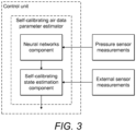
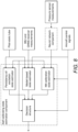
- Figure 1 shows components of the icing control system.
- embodiments of the icing control system include implementations with more blocks in the control unit than shown in Figure 1 and more blocks external of the control unit.
- a preferred implementation comprises the aircraft having only one set of sensors that provide atmospheric sensor measurements; only one set of sensors that provide external sensor measurements; only one set of sensors that provide air data estimates, which include pressure sensor measurements; only one power source; and only one self-calibrating air data parameter estimator component within the control unit. All of the other components, internal and external to the control unit, preferably have one or more duplicates.
- each wing has its own electro-thermal source and corresponding set of sensors for providing the surface temperature sensor measurements. Separate icing detection algorithms are implemented respectively for each arrangement of electro-thermal source and temperature sensors.
- the icing control system comprises the primary elements of:
- the control unit receives inputs from on-board sensors of atmospheric and other ambient conditions. If icing is detected, an intelligent control algorithm controls the power supplied to the electro-thermal sources in a way that is both appropriate for mitigating the ice formation and also minimizing power consumption.
- the External Sensor Measurements component includes an inertial measurement unit, IMU.
- An IMU is an electronic device that measures and reports a body's specific force, angular rate and the magnetic field surrounding the body. These measurements are obtained using a combination of accelerometers, gyroscopes, and magnetometers. The IMU supplies measurements of the specific force and angular rate of the aircraft.
- the External Sensor Measurements also include a pitot-static tube providing measurements of the relative velocity in the longitudinal axis of the aircraft; an engine speed sensor and control surface input measurements.
- the External Sensor Measurements also include a satellite receiver for obtaining location data from GNSS-based ground velocity measurements.
- the Air Data Measurements is data from a number of sensors, that are appropriately located about the aircraft, and provide pressure measurements and preferably also temperature measurements.
- the Atmospheric Sensor Measurements provides both ambient temperature and relative humidity measurements.
- the Surface Temperature Sensor Measurements is comprised of a sensor array preferably embedded at least in each wing. These sensor arrays supply the control unit with temperature measurements of the electro-thermal sources.
- Each electro-thermal source is a heating element.
- Each electro-thermal source may be made from carbon materials.
- each electro-thermal source is in the form of an electrically conductive carbon nanomaterial coating that is applied in a layer through a liquid carrier.
- the coating preferably comprises a mixture of graphene, carbon black and a bonding system in the form of polyurethane.
- Carbon black is virtually pure elemental carbon (approximately 97% pure) in the form of colloidal particles that are produced by incomplete combustion or thermal decomposition of gaseous or liquid hydrocarbons under controlled conditions. Its physical appearance is that of a black, finely divided pellet or powder.
- Graphene is an allotrope of carbon in the form of a two-dimensional, atomic-scale, honeycomb lattice in which one atom forms each vertex. It is the basic structural element of other allotropes, including graphite, charcoal, carbon nanotubes and fullerenes. Graphene has many extraordinary properties. It is about 100 times stronger than the strongest steel. It conducts heat and electricity efficiently and is nearly transparent.
- the electro-thermal sources may also be constructed form carbon nanotubes.
- Carbon nanotubes are seamless cylindrical hollow fibres, comprised of a single sheet of pure graphite (a hexagonal lattice of carbon, similar to a chain link fence), having a diameter of 0.7 to 50 nanometres with lengths generally in the range of tens of microns. Being a hollow tube comprised entirely of carbon, they are also extremely lightweight. The type of bond holding the carbon atoms together is very strong, plus the hexagonal pattern of the atoms themselves gives rise to a phenomenon known as electron delocalization. This means that under the right conditions electrical charge can move freely in a nanotube.
- the regular arrangement of the atoms also can vibrate in ways that effectively move heat through the tube, so thermal conductivity is high as well as electrical conductivity.
- these unique structures exhibit 200 times the strength and 5 times the elasticity of steel; 5 times the electrical conductivity, 15 times the thermal conductivity and 1,000 times the current capacity of copper.
- the structures also have almost half the density of aluminium.
- a preferred construction material for a UAV is carbon fibre.
- Carbon fibre is made of carbon crystals aligned in a long axis. These honeycomb shaped crystals organize themselves in long flattened ribbons. This crystal alignment makes the ribbon strong in the long axis. In turn these ribbons align themselves within fibres.
- the fibre shape is the original shape of the material (its precursor) used to produce the carbon fibre.
- electro-thermal source as a layered carbon material allows for good integration with a laminate carbon fibre structure.
- embodiments also include the use of other known types of electro-thermal source, such as aluminium or copper based electro-thermal sources.
- the internal resistivity, and therefore heating provided by the electro-thermal source is dependent on the thickness of the applied layer and the surface area of said layer.
- CNT Carbon Nanotube
- Figure 2 shows a preferable arrangement of an electro-thermal source on a wing and how power is supplied to the electro-thermal source.
- the electro-thermal source is only provided on the leading edge of a wing, which is the part of the wing that is most likely to experience icing.
- the top view shows the four steps in the process of applying an electro-thermal source as a layer on a wing.
- Step 1 is to apply a layer of an electrical insulator on the surface of the wing.
- step 2 a conductive bus bar, that is preferably copper, is then positioned on the layer of insulator.
- step 3 the electro-thermal source is then applied in a layer above the bus bar.
- step 4 another layer of electrical insulator is applied above the electro-thermal source. Power is supplied to the electro-thermal source through the bus bar. The power consumption of the electro-thermal source, and therefore heating of the surface of the wing, is dependent on the thickness, location, and layout of the electro-thermal source.
- an electro-thermal source is located at least in each wing of the aircraft.
- electro-thermal sources may also be provided on any other surfaces of the aircraft on which it is particularly important that icing is prevented of mitigated and/or if it is known that the surface is likely to experience icing.
- the power source for each electro-thermal source may be a battery pack, such as lithium polymer batteries. Alternatively, or in addition, electrical power can be supplied that is derived from the aircraft engine.
- the control unit receives inputs from external components that comprise measurement sensors. These inputs are processed by the internal components of the control unit to provide inputs to the control algorithm so that the control algorithm can determine how and when the power source is controlled to heat each electro-thermal source.
- control unit The internal components of the control unit are described below.
- the Self-Calibrating Air Data Parameter Estimator component obtains measurements from an array of sensors that are appropriately positioned about the aircraft.
- the sensors are comprised by the Air Data Measurements component and provide data for estimating the angle-of-attack (AOA), side-slip angle (SSA) and airspeed of the aircraft (commonly referred to collectively as the air data parameters).
- AOA angle-of-attack
- SSA side-slip angle
- air data parameters airspeed of the aircraft
- These parameters are directly related to the performance of the aircraft.
- the AOA will for example determine when the wing is under stall conditions which leads to a significant drop in lift force and large increase in separation of flow behind the wing.
- flying in icing conditions can result in an accretion of ice on the wings, which will alter the aerodynamic capabilities. This degradation in performance can be detected if the AOA is known.
- Each sensor preferably provides a pressure measurement and a temperature measurement. At least the pressure measurement, and preferably both the pressure and temperature measurements, are used as inputs to a machine-learning algorithm, that is preferably a neural networks algorithm, that provides the air data estimates, i.e. angle-of-attack, side-slip angle and airspeed.
- a machine-learning algorithm that is preferably a neural networks algorithm, that provides the air data estimates, i.e. angle-of-attack, side-slip angle and airspeed.
- These neural network obtained air data estimates are processed by a nonlinear observer algorithm that uses a model of the aircraft and optionally live data such as IMU measurements and/or location data (e.g. from a satellite navigation component), provided by the External Sensor Measurements component. This enables the nonlinear observer algorithm to estimate a correction term of the aircraft model and the neural network air data estimates, hence providing a method for online calibration of the complete air data estimation.
- the model-based icing detection algorithm receives inputs from the external sensor measurements component, in the form of, for example, angular velocities, specific force, and engine speed measurements, as well as estimates provided by the Self-Calibrating Air Data Parameter Estimator component. These inputs are used, by the model-based icing detection algorithm, to generate a mathematical model for detecting icing.
- the model-based icing detection algorithm detects ice when it forms on the aircraft during flight operations. It uses a mathematical model, that is an aerodynamic model, of the aircraft to detect structural, or aerodynamic faults, which are an indication that icing has formed.
- the algorithm uses estimates of aerodynamic parameters, that are obtained under standard flight conditions as reference data, and the mathematical model of the aircraft. Should the differences between the aerodynamic parameters and the mathematical model become substantial, and/or unexpected changes occur, a structural fault is detected. If the structural fault is indicative of icing forming on, for example, the leading edge of the wings of the aircraft, the algorithm generates a signal that alerts the central fault diagnosis algorithm component of the risk.
- the model-based icing detection algorithm may use the specific control signals of thrust and deflection angles. These can be either commanded or measured.
- the model-based icing detection algorithm preferably detects icing by implementing the icing detection techniques as disclosed in K.L. Sorensen, M. Blanke, T. A. Johansen; ⁇ Diagnosis of Wing Icing Through Lift and Drag Coefficient Change Detection for Small Unmanned Aircraft'; IFAC Safeprocess'15 - Paris, France; Volume 48; Issue number 21; Pages 541-546; ISSN: 1474-6670 .
- the electro-thermal-based detection algorithm provides another technique for icing detection.
- the icing detection performed by the electro-thermal-based detection algorithm and model-based icing detection algorithm are separate processes that make independent determinations on whether or not icing has occurred.
- the electro-thermal-based detection algorithm does not use an aerodynamic model of the aircraft. It instead uses a thermodynamic model of the system surrounding the aircraft wings and the electro-thermal sources.
- the thermodynamic model of the system includes the composite structure of each wing and the electro-thermal source in each wing, the airflow around the wing, water layers, and an ice layer.
- the inputs to the electro-thermal-based detection algorithm are supplied by the surface temperature sensors embedded in each wing and/or each electro-thermal source.
- each electro-thermal source is preferably located on the leading edge of an aircraft wing.
- the rate at which the temperature of the surface of a wing changes is dependent on whether or not ice has formed.
- the electro-thermal-based icing detection algorithm obtains measurements of wing surface temperatures after an electro thermal source has heated the wing surface. These are then used to determine temperature gradients as the wing is cooled by the environment. If the temperature gradients substantially differ, and/or change unexpectedly, from reference gradients, the formation of icing is detected and the algorithm produces a signal that alerts the central fault diagnosis algorithm.
- the Control Algorithm component preferably comprises a central fault diagnosis algorithm component that receives and assesses alert signals from the model-based icing detection algorithm component and electro-thermal-based detection algorithm component of the control unit.
- Embodiments also include the central fault diagnosis algorithm component being provided as a separate component to the Control Algorithm.
- the central fault diagnosis algorithm component uses external measurements and reference data to automatically assess the present situation and determine whether or not icing has occurred and/or is likely to occur. If the external measurements indicate a reduction in thrust, more thrust is required to achieve the desired altitude, or more thrust is required to maintain the desired airspeed, while the icing detection algorithms have raised alarms, then it is appropriate to determine that icing has occurred and is a cause for the need for more thrust.
- the central fault diagnosis algorithm component determines that icing has occurred, and/or that icing is likely to occur, then it outputs a signal that informs the control algorithm component of this.
- the control algorithm component can then change its mode of operation so that any icing formation is appropriately mitigated or prevented.
- the control algorithm has the purpose of controlling the supply of power by the power source to the electro-thermal sources.
- the power supply is controlled to be sufficient, and in the required manner, for the electro-thermal based detection of icing to be performed. If icing is detected, then the power supply is controlled to be sufficient, and in the required manner, for icing prevention, or icing mitigation, to be performed. By ensuring that only the required power is used for specific and necessary tasks, the power consumption as a result of providing an icing solution is minimised.
- the control algorithm sends a signal to the power source component that specifies how much current should flow through the electro-thermal source in the surface and for what time period.
- the operation of the control algorithm is dependent on the power source as well as the internal composition and structural layout of the electro-thermal source.
- the control of the power source by the control algorithm may be dependent on the amount of power remaining in the power source and/or the power that the power source is able to provide at that particular time.
- the control algorithm receives signals from the central fault diagnosis algorithm component that informs it if icing has been detected.
- the control algorithm also receives inputs from the Atmospheric Sensor Measurements component, that indicate possible icing conditions through ambient temperature and relative humidity measurements, and from the surface temperature sensors.
- the control algorithm can automatically change its mode of operation in dependence on the received data.
- the data received by the control algorithm from the Atmospheric Sensor Measurements component allows the control algorithm to determine if the present weather conditions are conditions in which icing can, or is likely to occur. If the data received by the control algorithm from the Atmospheric Sensor Measurements component indicates that icing is not likely to occur, then the control algorithm preferably operates in a mode in which no icing detection or prevention/mitigation is performed. Advantageously this prevents unnecessary power consumption caused by operating the icing detection and icing prevention/mitigation systems when icing is unlikely to occur. As soon as the data received by the control algorithm from the Atmospheric Sensor Measurements component indicates that icing can occur, or is likely to occur, then the control algorithm preferably starts to operate one or both of the icing detection algorithms according to embodiments.
- the control algorithm can operate in different modes as required for:
- the icing detection mode provides a combined operation of the electro-thermal-based icing detection algorithm and the control algorithm.
- the control algorithm provides heating of the electro-thermal sources by controlling the power source component to provide rapid power bursts to the electro-thermal sources that result in a corresponding heating of the electro-thermal sources.
- the electro-thermal-based icing detection algorithm uses this heating pattern to obtain estimates of surface temperature gradients and thereby detect if icing has occurred. This may be the default mode of operation of the control algorithm under all flight conditions until the mode of the control algorithm changes due to icing being detected.
- the anti-icing mode prevents icing from forming on surfaces by ensuring that the electro-thermal sources heat the surfaces to maintain the surface temperature at a specified level above freezing. This can be achieved through a feedback control in which the control algorithm uses the input received from the surface temperature sensor measurements and a pre-defined temperature set-point, i.e. desired electro-thermal source temperature. This mode is only active when it has been primed, i.e. activated. The activation may be performed in response to feedback from the atmospheric sensor measurements.
- the purpose of the de-icing mode is to reduce power consumption by mitigating, rather than preventing, ice formation.
- Ice is allowed to form on surfaces.
- the de-icing procedure is activated and the control algorithm generates a signal to the power source.
- the power source provides the electro-thermal sources with a succession of shorter power bursts, each burst followed by a longer period where no power is supplied by the power source. This process should result in short period of ice formation on a surface, followed by a rapid temperature increase of the surface and therefore aerodynamic ice shedding.
- the anti-icing procedure typically has a lower peak-power requirement than that of the de-icing procedure.
- anti-icing requires a larger average power than de-icing and is therefore a greater drain on the power source.
- the anti-icing procedure requires maximum power from the power source only to achieve a desired set point temperature. Once that temperature has been achieved, the power consumption required to maintain the desired temperature is lower than maximum, depending primarily on atmospheric conditions and the electro-thermal source layout.
- the de-icing procedure requires maximum power to achieve a desired set point temperature, like the anti-icing approach.
- the set point temperature for the de-icing however is higher and more time with the maximum power is required.
- the maximum power is only required until the set point temperature has been reached, or until icing has been shed.
- the difference from the anti-icing approach is that the set point temperature for the de-icing approach is not maintained throughout operations in icing conditions.
- the de-icing is only active when icing is present and then power is only required for shorter bursts, typically less than 60 seconds, followed by a cooling period, where potential icing is allowed to form on the exposed surface.
- the icing control system comprises components for automatically detecting icing and automatically preventing, or mitigating, the presence of icing in an energy efficient way.
- the icing can be detected by the model-based icing detection algorithm and/or the electro-thermal-based detection algorithm.
- An advantage of the model-based icing detection algorithm is that it does not require heating of the electro-thermal sources and it therefore requires less power than the electro-thermal-based detection algorithm.
- An advantage of the electro-thermal-based detection algorithm is that it can generally be expected to be more accurate than the model-based icing detection algorithm because the detection is based on temperature measurements from the actual surface on which it is desired to detect icing rather than a model of any of the conditions at the surface.
- Embodiments include the model-based icing detection algorithm and the electro-thermal-based detection algorithm both operating simultaneously and in parallel with each other from as soon as it is determined to start icing detection (which may be either from the start of the flight or in response to potential icing conditions being detected). The icing control system then determines whether or not icing has occurred in dependence on the outputs of both of the detection algorithms.
- embodiments also include the icing control system alternatively operating with only the model-based icing detection algorithm or only the electro-thermal-based detection algorithm and only one of the model-based icing detection algorithm and electro-thermal-based detection algorithm ever being used for icing detection.
- a preferred way of operating the icing control system is for the model-based icing detection algorithm to be operated continuously either from as soon as a flight has started, or, preferably, from as soon as atmospheric conditions with icing potential are detected.
- the electro-thermal-based detection algorithm which requires more energy to operate, is initially operated infrequently, or, preferably, not operated at all.
- the electro-thermal-based detection algorithm is then operated either on its own or together with the model-bases icing detection algorithm in order to corroborate the determination by the model-based icing detection algorithm.
- Embodiments also include the electro-thermal-based detection algorithm being operated more frequently, such as continuously from as soon as the flight has started or from as soon as atmospheric conditions with icing potential are detected.
- the de-icing or anti-icing modes are only started once the electro-thermal-based detection algorithm detects icing.
- the icing detection is performed in an energy efficient way since the more accurate, but more power consuming, electro-thermal-based detection algorithm is only used frequently after icing has already been detected as occurring, or likely to occur, by the model-based icing detection algorithm.
- the icing control system is highly suited to implementation on small UAVs.
- Embodiments therefore provide an icing control system that is an intelligent icing protection solution, IPS, that uses intelligent algorithms for both detecting icing and controlling processes for preventing, or mitigating, icing formation on the exposed surfaces of a UAV.
- the icing protection solution is based on the primary elements of: 1) electro-thermal sources 2) an intelligent control unit, and 3) a power source.
- the control unit is primed by an on-board atmospheric sensor package, measuring ambient environmental conditions. Once the risk of icing is established, two ice detection algorithms - working in parallel - are activated. This approach ensures robustness and accuracy. If icing is detected, the control algorithm controls the supply of power to the electro-thermal sources, thereby achieving temperature control of each thermal source, while minimising power consumption.
- Whether or not anti-icing or de-icing is performed may be predetermined prior to each flight based on the weather conditions, or automatically determined during a flight based on the weather conditions. For example, if there are many clouds at the altitude of operation, then only performing anti-icing would be appropriate, as the risk of icing would be more or less permanent. However, if the altitude of operation was above a cloud cover, only performing de-icing would be appropriate as icing would only be an issue climbing or descending through the cloud cover.
- Embodiments of the invention that provide the new technique for detecting icing using electro-thermal sources are described in more detail below.
- the determination made by the electro-thermal-based icing detection algorithm is based on the thermodynamic system surrounding each electro-thermal source, the corresponding aircraft surface and ambient conditions.
- the algorithm uses residuals and statistical change detection to determine if ice formation has occurred.
- thermodynamic system When an aircraft is operating in non-icing conditions, there is a thermodynamic system that comprises the aircraft wings, the electro-thermal sources, a water layer (depending on atmospheric conditions), and the airflow surrounding the aircraft. When icing occurs then the thermodynamic system comprises another element and this results in a significant change to the flow of energy in the system. It is this change in energy flow that the electro-thermal-based icing detection algorithm uses to determine that icing has occurred.
- a specific embodiment is now considered in which there is an array of K-type thermocouples embedded in an electro-thermal source/wing that provide temperature measurements of the surface of an aircraft wing.
- the electro-thermal source is activated in a specific on/off pattern in which the either the entire electro-thermal source is heated or none of the electro-thermal source is heated.
- the heating pattern enables temperature gradient estimation.
- thermodynamic theory is proved below.
- T ETS the average temperature of the electro-thermal source
- Eqn. 1 is based on thermal energy balance for a given thermodynamic system.
- the energy out of the system is assumed to be a result of thermal convection alone and the generated energy comes from the electrical heating of the electro-thermal source.
- the rate of thermal convection, q ⁇ C can be equated with the temperature drop of the body volume, i.e. the volume of the electro-thermal source, overtime, as shown in Eqn. 2.
- ⁇ and c p are the density and specific heat capacity of the electro-thermal source, respectively.
- V and A are the volume and area of the electro-thermal source, respectively.
- h is the convective heat transfer coefficient.
- Eqn. 6 is a mathematical expression that implies that the electro-thermal source assumes the temperature of the surroundings at an exponentially decaying rate governed by the thermal time constant ⁇ .
- Eqn. 6 For detection purposes the expression on the right hand side of Eqn. 6, including the theoretical thermal time constant of Eqn. 4 serves as a reference. The left hand side of Eqn. 6 is the measurable quantity. Consequently the resultant residual can be defined as: r ⁇ ⁇ T 0 e ⁇ t / ⁇ ⁇ ⁇ T t where r ⁇ 0 when no icing has occurred and r ⁇ 0 when icing has occurred.
- a robust criterion should evaluate average
- ⁇ T 0 e - t / ⁇ in Eqn. 7 is the theoretical (or nominal) response and ⁇ T ( t ) is its measured equivalent. Icing is said to be present when the measured temperature response (or signature) deviates from the nominal response.
- Thermal convection occurs as energy transfer due to diffusion and by bulk (or macroscopic) motion of a fluid. This motion is attributed to large number of molecules moving collectively or as aggregates. In the presence of a temperature gradient such motion contributes to the transfer of thermal energy. As molecules in aggregate maintain their random motion, the combined thermal transfer is due to the superposition of energy transferral by random motion of the molecules and the bulk motion of the fluid.
- the coefficient h [ W /( m ⁇ K )] is termed the convective heat transfer coefficient.
- the convective heat transfer coefficient is a highly intricate quantity to predict and it is tightly linked to the motion of the fluid flowing around the body that is heated or cooled.
- the boundary layer can be in either a turbulent or laminar flow regime, where the latter is characterised by the fluid flowing in parallel layers, i.e. there is no transferral of fluid particles between the parallel layers, nor any swirls or eddies.
- Properties concerning the laminar flow regime is a high momentum of diffusion and a lower momentum of convection. We assume here that the flow around relevant areas of a given aerofoil is laminar.
- Re is a dimensionless quantity that aides the characterisation and quantification of different flow regimes and is known as the Reynolds number, Re, which is defined as the ratio of momentum forces to viscous forces. Laminar flow generally occurs at low Reynolds numbers (though still at Re > Re >10 4 for aerofoils, where viscous forces are more dominant, or where the flow velocity is less dominant).
- Re is defined as where V ⁇ is the free stream flow velocity, x c is a characteristic linear dimension (for aerofoils this corresponds to the chord line), and v is the kinematic viscosity of the fluid in which the aerofoil operates.
- Pr The Prandtl number ( Pr ) is another significant parameter. It can be summarised as the ratio of molecular kinematic viscosity to the molecular thermal diffusivity, and is defined as
- a thermal boundary layer When a temperature difference exists between a solid and the free stream of a fluid flowing past, a thermal boundary layer is present, with thickness ⁇ t , different from the thickness of the boundary layer ⁇ .
- Heat transfer at the surface is by conduction and, as such where k f is the conductivity of the fluid, T is the temperature at a given point in the thermal boundary layer, and y is a perpendicular distance from the surface of the solid.
- the term on the left of the equality corresponds to Fourier's law (of thermal conduction) in one-dimensional space. Rearranging Eqn. 11 and multiplying by the inverse of a characteristic linear dimension results in which is known as the Nusselt number ( Nu ) and can be summarised as the ratio of conductive thermal resistance to the convective thermal resistance of the fluid.
- a Nusselt number close to 1 signifies laminar flow, where larger values for Nu correspond to a turbulent flow.
- Thermal convection is generally divided into two main classifications. These are related to the driving force causing the flow. For the work presented in this document focus is limited to forced convection, as opposed to free or natural convection. Forced convection is the classification applied for describing convection, where fluid circulation is produced by an external agent, such as wind, a fan, or the forced movement of a body through a fluid.
- Methods such as this in which icing is detected based on comparing a response to a known response for non-icing conditions, benefit from requiring less energy consumption than methods which detect icing by detecting when the temperature response flattens for melting due to the input energy supplying the latent heat of fusion.
- the model parameters are as follows:
- the simulation environment was generated using the commercial COMSOL Multiphysics finite-element software package.
- COMSOL supports fully transient, multi-dimensional, nonlinear, thermal finite-element modelling, including temperature dependent material properties and complex boundary conditions.
- the simulation environment developed mimics that of a wind icing tunnel.
- the total simulation time is 60 seconds and for the remainder of the simulation period the electro-thermal source does not have any electrical power supplied to it such that, after sufficient time, the thermodynamic system returns to equilibrium.
- the icing detection is based at least on the temperature profile that starts as soon as the heating of the electro-thermal source is stopped, i.e. when the temperature of the surface is falling due to cooling of a surface by its external environment.
- the temperature profile in the cooling phase is advantageous over that in the heating phase since it depends on changes in heat convection coefficient rather than specific heat coefficient. That is to say, the temperature profile in the heating phase is dominated by the heat capacity of the surface.
- the temperature profile during the cooling phase is influenced more by the convective flow of heat from the surface to the environment.
- the temperature profile during the cooling phase can be determined over a longer period of time than in the heating phase and is therefore both more affected by convective flow and the longer measurement period allows it to be determined more accurately.
- Using the temperature profile during the cooling phase also does not require accurate control of the heating of the electro-thermal source and a temperature profile for determining if icing has occurred is still obtained when the electro-thermal source is heated intermittently and with a variable and unknown amount of power.
- a simulated dataset has been obtained with an icing layer applied to the leading edge of the aerofoil and another dataset has been obtained under the same condition but without the icing layer.
- the icing layer is 2 mm at its thickest, which coincides with the leading edge of the aerofoil.
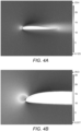
- Figures 4A and 4B show the simulation environment with an ice layer applied to the leading edge of an aerofoil of the X8 Skywalker.
- the X8 Skywalker is a UAV that is a commercially available for civilian applications. See, for example: http://www.fpvmodel.com/latest-version-skywalker-black-x8-flying-wing-_g632.html (as viewed on 10/8/2016).
- the X8 Skywalker is a UAV that the icing control system according to embodiments can be integrated into in order to improve the performance of the UAV in icing conditions.
- Figure 4A shows the airflow distribution around the X8 Skywalker's aerofoil.
- Figure 4B is a close up view of the leading edge of the aerofoil and shows the applied ice layer.
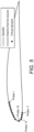
- probes i.e. virtual sensors
- Their locations are provided in Table 1 and shown in Figure 5 .
- the location is expressed by 'a' for 'atop' (i.e. on the top surface) or 'u' for 'under' (i.e. on the bottom surface) and by the chord line length from the leading edge of the aerofoil.
- Table 1 Probe No. Chord Line Length (mm) Location (a/u) [1, 9] [45.00, 5.00] a 10 0.00 - [11, 14] [20.00, 5.00] u
- the temperature of the aircraft surface is an acceptable proxy. Positioning the sensors to measure the temperature of the aircraft surface, rather than the surrounding air, allows for more accurate temperature control in anti-icing and de-icing modes. Thus, positioning the sensors on/in the aircraft surface means that only one set of sensors is required for both icing detection and anti-icing/de-icing control.
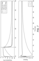
- the results of the simulations are shown in Figure 6 .
- the responses form probes 1, 2 and 3 when obtained from simulations conducted in icing conditions show a different type of behaviour from the other sensors. This is because the icing layer did not cover these three specific probes. Modelling not all of the virtual sensors being covered with the ice layer was appropriate as it models a likely circumstance in actual icing conditions. Aside from these three deviating virtual sensor responses, there are clear thermal patterns in the data. The most relevant is a comparison of the profile of each response when in icing and in non-icing conditions. These temperature profiles clearly show the impact of the ice layer on the thermal time constant. Another characteristic that can be seen in the data is the temperature deviation of the virtual sensor located at the very leading edge, to the rest of the sensors.
- Figure 7 shows simulated responses of the average temperature for datasets obtained in non-icing and icing conditions. The figure also shows the simulated residual signal.
- ⁇ T n ( t ) is the average electro-thermal source temperature for simulations conducted for non-icing conditions, while the response identified by ⁇ T t ( t ) shows the average temperature of the electro-thermal source for simulations conducted for icing conditions.
- ⁇ T ⁇ n ( t ) is the response of the expression found in Eqn. 6 with the thermal constant determined by Eqn. 4. This latter response serves as a reference of the temperature profile for non-icing conditions.
- the two signals r n and r i denote the residual signal for non-icing and icing conditions, respectively.
- the temperature profile for when no icing has occurred may be a predetermined profile that is permanently stored and used for all icing detection measurements.
- the predetermined profile may be the same for all of the specific type of UAV with the specific electro-thermal source and temperature sensor arrangements.
- the predetermined temperature profile may be determined for each specific UAV by measuring the temperature profile in non-icing conditions and then storing this profile.
- a preferred implementation is for the temperature profile to be measured for each flight by the UAV by measuring the temperature profile at the start of the flight as it is known that at this time substantially no icing has occurred. The measured temperature is then stored and re-used later as the temperature profile for when no icing has occurred.
- the residual has a very different characteristic when icing has occurred and can therefore be used to detect icing.
- an algorithm may determine that icing has occurred if the average magnitude of the residual, in the time period between 2 seconds after heating has stopped and 5 seconds after heating has stopped, is greater than or equal to 0.5, and that icing has not occurred if the average magnitude of the residual, in the time period between 2 seconds after heating has stopped and 5 seconds after heating has stopped, is less than 0.5.
- These detection criteria are exemplary and embodiments include many other icing detection criteria based on measured temperatures, and/or a measured temperature profile being used.
- the determination that icing has occurred may be made in dependence on a comparison with one or more reference profiles of responses when icing has or has not occurred. Reference profiles may be generated from previously measured data for the aircraft or theoretically calculated data.
- Embodiments also include using any of the above techniques to further estimate how thick the ice layer is when icing has occurred.
- An estimation of the thickness of the ice layer is obtained from the gradient/shape of the temperature profile, the temperature profile being dependent on the thickness of the ice layer.
- a preferred implementation is for separate electro-thermal sources to be provided on the leading edges of each wing of a UAV.
- Each electro-thermal source is provided in the surface of a wing.
- each electro-thermal source is a layer of Carbon material as described earlier in the present document.
- each electro-thermal source is integrated within the wing, the wing itself having a laminate structure and being made from Carbon fibre.
- each electro-thermal source arranged on a surface of a UAV is dependent on the type of UAV, which surface of the UAV the electro-thermal source is arranged on and the specific arrangement of the electro-thermal source on the surface.
- the length of time for which the electro-thermal source is heated is preferably in the range 1 to 15 seconds, and more preferably less than 10 seconds.
- the applied power to the electro-thermal source is preferably in the range 1000W to 10000W for each 1m 2 of the surface that is covered by the heating element.
- each wing there are temperature sensors arranged on and/or in the surface of each wing that cover the region of the wing that is heated by the electro-thermal sources.
- the temperature profile is preferably based an average of some, or all, of the temperatures of the plurality of temperature sensors as the surface of the wing cools.
- the temperature of the surface is also measured when the surface is being heated.
- the determination if icing has occurred on the surface can then be dependent on measured temperatures of the surface when the surface is heated as well as when the surface cools.
- an accurate determination can be made based on temperature data as the surface cools alone, this embodiment allows a determination to be based on more measured temperature data.
- Embodiments also include providing a plurality of electro-thermal sources in a same wing with each electro-thermal source arranged to heat a different part of the surface of the wing.
- each electro-thermal source By operating separate icing detection processes for each electro-thermal source, a determination can be made of which surfaces of the wing icing has occurred on. This allows efficient anti-icing or de-icing to be performed as only the surfaces of the wing on which icing has occurred need to be heated.
- the electro-thermal sources are preferably sequentially heated, either individually or in groups, so that power is not supplied to all of the electro-thermal sources at the same time.
- this lowers the peak instantaneous power that the power source of the electro-thermal sources has to provide to the electro-thermal sources and allows for easier implementation and more efficient operation of the power source.
- Embodiments also include applying the techniques as disclosed in K.L. Sorensen A.S, Helland, T.A. Johansen; 'Carbon nanomaterial-based wing temperature control system for in-flight anti-icing and de-icing of unmanned aerial vehicles'; 2015 IEEE Aerospace Conference; 7-14 March 2015; Pages:1 - 6; ISSN :1095-323X; Print ISBN:978-1-4799-5379-0 .
- Embodiments also include applying the techniques as disclosed in K.L. Sorensen A.S, T.A. Johansen; 'Thermodynamics of a Carbon nano-materials based icing protection system for unmanned aerial vehicle'; 2016 IEEE Aerospace Conference; 5-12 March 2016; pages: 1 - 10; INSPEC Accession Number:16121843 .
- Embodiments of the invention that provide the new Self-Calibrating Air Data Parameter Estimator component, that is more generally an air data estimation component, for the model-based icing detection algorithm for detecting icing are described in more detail below.
- Embodiments solve this problem by providing an air data parameter estimation system that only requires measurements that are obtainable for a UAV through a combination of standard sensor suite measurements and small sensors embedded in the surface of the UAV.
- the model-based technique according to embodiments is based on a combination of a machine learning algorithm, preferably a neural network (NN) algorithm, together with air data parameter state estimators.
- NN neural network
- embodiments provide an accurate, robust and low-cost method of estimating the air data parameters for a UAV.
- the techniques according to embodiments are particularly appropriate for UAVs but may also be applied to other aircraft than UAVs.
- Embodiments provide a two layered approach to estimating air data parameters.
- the first layer is the application of a machine learning algorithm.
- the second layer is the application of one or more state estimation algorithms that operate on the outputs of the machine learning algorithm.
- the ML approach is normally associated with higher accuracy, but comes with the weakness of being sensitive to structural changes in the sensor setup. If one sensor output changes slightly due to wear or a tiny change in position/alignment of sensor, the output of the ML component can potentially degrade a significant amount.
- the machine learning algorithm maps a pressure distribution, and preferably also a temperature distribution, over the UAV to air data parameters.
- the ML component is trained using data that contains information on these input-output relations and approximates the underlying unknown mathematical function from input to output, so that the ML component is capable of providing a set of air data parameter estimates if given a set of pressure measurements.
- a particularly preferred embodiment is for the machine learning algorithm to be a neural network and embodiments are presented herein with the machine algorithm being a neural network.
- the method has been tested using two different ML algorithms, artificial neural networks (NNs) and linear regression (LR).
- embodiments include the use of any parameter estimation algorithm capable of mapping pressures and/or temperatures over the UAV to air data parameters.
- embodiments include the use of genetic algorithms, logistic regression and support vector machines.
- a plurality of pressure and/or temperature sensors are positioned over, and embedded in, the external surface of the UAV.
- An advantage of embodiments is that there is a lot of flexibility in the sensor placement and so embodiments can be used with a large range of sizes and designs of UAV. Depending on the subject aircraft of implementation, this potentially allows equipping a UAV with an air data parameter estimator system, where other solutions are not viable.
- An example could be a UAV that is driven by a propeller on the nose of the aircraft, which denies use of a nose flush air data sensing (FADS) system.
- FADS nose flush air data sensing
- each specific sensor arrangement on each specific design of UAV will preferably be provided with a new set of training data for the neural network.
- the below described second layer of the air data parameter estimation technique corrects the small inaccuracies between individual UAVs with the same design and sensor arrangement. There is therefore no need to individually calibrate each individual UAV and techniques according to the embodiments are therefore highly scalable.
- Each sensor is preferably a MEMS-based Piezo-resistive pressure sensor.
- An example of a particularly preferably sensor is the Bosch280: https://www.bosch-sensortec.com/bst/products/all_products/bmp280, as viewed on 16 th August 2016. This is a combined pressure and temperature sensor that has a low cost, small size and low power consumption. This type of sensor can be used with small UAVs, whereas large and expensive pitot probes cannot. It can be connected to a microcontroller, for example via an SCSI (small computer system interface) parallel interface (SPI). Wire-based communication relieves the setup of rubber tubes connected to an expensive pressure scanner.
- SCSI small computer system interface
- SPI small computer system interface
- a positioning of the sensors over the surface of the UAV is four sensors on the top of each wing, one sensor on the bottom of each wing, three sensors on the top of the nose of the UAV, two sensors on the front-sides of the nose of the UAV and one sensor on the bottom of the nose of the UAV.
- the positioning of the sensors is therefore strategically chosen so that sensors are provided in the most appropriate locations for measuring temperatures and/or pressures.
- the training data for the neural network may be obtained from one or more of measured data in a wind tunnel, measured data during actual flights or from software simulations, for example created using computational fluid dynamic (CFD) software or panel method software.
- CFD computational fluid dynamic
- PTU pan-tilt unit
- the inputs to the neural network preferably have little filtering and a high update rate. Although this will, at least initially, result in less accurate estimates by the neural network, it will provide the basis for more accurate estimates in highly dynamic flight conditions.
- the output of the first layer neural network component is an estimate of the air data parameters of the UAV.
- This output is provided to the second layer of the air data parameter estimation technique according to embodiments, that automatically applies a calibration to the air data parameter estimates. Any inaccuracies in the sensor outputs due to wear or applying the sensor set-up to a UAV that the neural network was not specifically trained for are advantageously compensated for by the applied calibration by the second layer to thereby provide a robust and fault tolerant system.
- the first layer algorithm implements a further, separate, neural network in addition to that for providing the main air data estimates as described above.
- the further neural network is configured to detect whether the sensor measurements are coherent with respect to each other and to exclude any faulty sensor readings. This allows the training of a number of new individual neural networks to handle the situation in which there is a specific loss of a sensor. For example, if one of the sensors starts outputting measurements that are estimated to be faulty, a network is trained using the other sensors and is used for air data parameter estimation instead.
- the second layer of the air data parameter estimator system can be a signal-based or model-based observer. According to embodiments it is a state estimator component structure. This component consists of one or more state estimation algorithms running simultaneously that filter the neural network component estimates by using a mathematical model of the UAV, and optionally sensor measurements, to correct any inaccuracies of the neural network component estimates.
- the state estimator can either be combined with the ML component by a frequency-based addition of the signals, or by having the state estimator component treating the ML component as a virtual air data parameter sensor.
- the state estimation component is preferably configured to obtain estimates of the air data parameters by using a different state estimation algorithm that does not utilise the neural network component estimates. This provides a complete air data parameter estimation system that is capable of handling any situation that a UAV may experience.
- FIG. 8 A block diagram of an embodiment of the air data parameter estimation system is shown in Figure 8 .
- a number of different state estimators are provided in parallel and the different state estimators may operate simultaneously.
- Embodiments also include the use of other state estimation algorithms for obtaining estimates of the air data parameters further to those specifically shown in Figure 8 .
- the inertial measurement unit (IMU), global navigation satellite system (GNNS) receiver, and differential pressure pitot-static probe are provided as a sensor suite on a UAV. Note that the differential pressure pitot-static probe only provides a relative velocity measurement in the forward direction of the UAV.
- the air data estimation system of embodiments obtains air data estimates in all three dimensions.
- the Persistency-of-Excitation State Estimator component preferably estimates air data parameters by implementing the techniques as disclosed in Johansen, T. A., Cristofaro, A., Sorensen, K. L., Hansen, J. M., & Fossen, T. I. (2015, June); 'On estimation of wind velocity, angle-of-attack and sideslip angle of small UAVs using standard sensors'; in 2015 international conference on unmanned aircraft systems (icuas); (pp. 510-519). IEEE .
- the Persistency-of-Excitation State Estimator component is an observer component that requires only standard sensors and does not rely on a mathematical model of the aircraft. Although the observer component does require a flight pattern that is consistently excited, the excitation arising from the environment and normal flight envelopes is sufficient. Furthermore, implementing the ML component as a virtual sensor removes this requirement.
- the Persistency-of-Excitation State Estimator component further preferably estimates air data parameters by implementing the techniques as disclosed in A.W. Wenz, T. A. Johansen, A. Cristofaro; ⁇ Combining model-free and model-based Angle of Attack estimation for small fixed-wing UAVs using a standard sensor suite'; 2016 International Conference on Unmanned Aircraft Systems (ICUAS); 7-10 June 2016; Page(s):624 - 632 .
- This state estimator also includes a lift coefficient estimation.
- the Model-Based State Estimator component preferably estimates air data parameters by implementing the techniques for estimating air data parameters as disclosed in K.L. Sorensen, M. Blanke, T. A. Johansen; ⁇ Diagnosis of Wing Icing Through Lift and Drag Coefficient Change Detection for Small Unmanned Aircraft'; IFAC Safeprocess'15 - Paris, France; Volume 48; Issue number 21; Pages 541-546; ISSN: 1474-6670 , or Borup, K. T., Fossen, T. I., & Johansen, T. A. (2016) 'A Nonlinear Model-Based Wind Velocity Observer for Unmanned Aerial Vehicles In Non-linear control systems (nolcos) '. This relies on a mathematical model of the UAV, a standard sensor suite, and the aircraft control signals. There is no restriction on flight pattern with respect to excitation of this estimator.
- the NN Calibration State Estimator component is a model-based state estimator that receives the neural network component air data parameter estimates as inputs.
- This state estimator uses measurements from the UAV sensor suite along with the aircraft control signals.
- the NN Calibration State Estimator may use the specific control signals of thrust and deflection angles. These can be either commanded or measured.
- the state estimator functions as a filter for the neural network component air data parameter estimates.
- the resulting output is more accurate air data parameter estimates that include a self-calibration that corrects inaccuracies that are a consequence of changes in pressure sensor setup (such as small structural differences that occur when installing the pressure sensors on a new UAV).
- the Decision Structure component receives as inputs the outputs of the state estimators and determines to generate a state estimate, that is an estimate of the air data parameters, as its output in dependence on one or more of the received inputs, the determination being dependent on the input data and the current flight trajectory of the UAV.
- the output air data parameters from the Decision Structure component may be the same as one of the received inputs of the Decision Structure component, the determination by the Decision Structure component being only to select which of the received air data parameters to output given the current flight conditions.
- Embodiments therefore advantageously obtain air data parameter estimates by one of a plurality of techniques that include the new technique of combining machine learning or parameter estimation techniques with observer theory-based state estimation algorithms. This provides self-calibration for small structural changes between individual sensor setups and reduces the effect of any errors caused by minor sensor degradation. Embodiments are highly scalable and allow for flexible placement of the pressure/temperature sensors.
- a possible augmentation of the method is adding a third layer to the estimator structure (before or incorporated into the Decision Structure).
- This could consist of a Kalman filter that takes any number of air data parameter estimators as input and treats the input as Wiener processes, white nose, or Markov models.
- This method allows for a modular approach to estimating the air data parameters where any number of combinations of the above mentioned estimators can be combined into a single output structure, where specifics of the Kalman filter is chosen based on the performance characteristics of the input estimators.
- a sensor-based air data parameter estimator and a self-calibrating air data parameter estimator could both be connected to a third layer Kalman filter that in turn produces the final output of the augmented system.
- This structure could consist of any number of different configurations, e.g. the self-calibrating air data parameter estimator in parallel with two model-based estimators and three sensor-based estimators into the third layer Kalman filter.
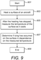
- FIG. 9 is a flowchart that shows a process for determining if icing has occurred on a surface of an aircraft according to an embodiment.
- the process begins.
- the surface of an aircraft is heated.
- the temperature of the surface is measured as it cools, after the heating has stopped.
- a determination is made if icing has occurred on the surface in dependence on the measured temperature.
- the process ends.
- the icing control system comprises a computing system for implementing all of the algorithms and other processes according to embodiments.
- methods and processes described herein can be embodied as code (e.g., software code) and/or data.
- code and data can be stored on one or more computer-readable media, which may include any device or medium that can store code and/or data for use by a computer system.
- a computer system reads and executes the code and/or data stored on a computer-readable medium, the computer system performs the methods and processes embodied as data structures and code stored within the computer-readable storage medium.
- one or more of the steps of the methods and processes described herein can be performed by a processor (e.g., a processor of a computer system or data storage system).
- a processor e.g., a processor of a computer system or data storage system.
- computer-readable media include removable and non-removable structures/devices that can be used for storage of information, such as computer-readable instructions, data structures, program modules, and other data used by a computing system/environment.
- a computer-readable medium includes, but is not limited to, volatile memory such as random access memories (RAM, DRAM, SRAM); and non-volatile memory such as flash memory, various read-only-memories (ROM, PROM, EPROM, EEPROM), magnetic and ferromagnetic/ferroelectric memories (MRAM, FeRAM), and magnetic and optical storage devices (hard drives, magnetic tape, CDs, DVDs); network devices; or other media now known or later developed that is capable of storing computer-readable information/data.
- Computer-readable media should not be construed or interpreted to include any propagating signals. Embodiments include a number of modifications and variations to the embodiments as described above.
- Embodiments implement both a model-based icing detection algorithm and an electro-thermal-based detection algorithm.
- the use of two algorithms increases the robustness and reliability of the system.
- Embodiments can be used to detect and/or prevent icing on any surface of an aircraft. These include any of aircraft's wings, rotary wings, stabilisers, propellers, rotors, exposed measurement instruments (such as pitot tubes) and antennas.
- Embodiments include the use of more than one power source.
- the power source that is used to heat the electro-thermal sources may be separate from that used to power the processing by the icing control system.
- the control unit as shown in Figure 1 may comprise more than one of any of the shown blocks.
- the central fault diagnosis algorithm as shown in Figure 1 is configured to detect faults that are related to icing. Embodiments also include this component detecting all faults that may occur, not only those related to icing. An example of a non-icing fault is the loss of a sensor measurement. Icing is therefore just one of a plurality of faults that can be mitigated, or prevented by the control system.
- Embodiments also include using the machine learning component, that is preferably a neural network, for other applications.
- the air data parameter estimation system of embodiments provides accurate measurements in three dimensions. However, this may not be necessary for certain applications.
- AOA and airspeed estimates may be made during cruise immediately after take-off, and then a change detection algorithm may be run on these values continuously after the UAV transitions into unknown flight conditions that could result in icing. This results in estimate biases and inaccuracies cancelling out and thereby providing a simple means for detecting icing.
- the machine learning component is capable of functioning as a standalone algorithm with its output directly connected to an icing detection algorithm.
- Embodiments are particularly appropriate for implementation in UAVs, more particularly in small UAVs. However, embodiments are also applicable to other aircraft, including standard human piloted aircraft.
- Embodiments include the use of any other type of electro-thermal source form that described above.
Landscapes
- Engineering & Computer Science (AREA)
- Aviation & Aerospace Engineering (AREA)
- Control Of Resistance Heating (AREA)
- Traffic Control Systems (AREA)
- Investigating Or Analyzing Materials Using Thermal Means (AREA)
Claims (10)
- Procédé de détection de givrage sur une surface d'un aéronef présentant des ailes et une source électro-thermique située au moins dans chaque aile, le procédé comprenant :la réception d'une détermination du fait qu'un givrage s'est produit par un premier système de détection de givrage ;dans lequel le premier système de détection de givrage comprend un algorithme à base électro-thermique utilisant un modèle thermodynamique d'un système entourant les ailes d'aéronef et les sources électro-thermiques ; dans lequel le premier système de détection de givrage détecte un givrage par un procédé comprenant :le chauffage d'une surface de l'aéronef ;après l'arrêt du chauffage, la mesure de la température de la surface pendant qu'elle refroidit ; etla détermination du fait qu'un givrage s'est produit sur la surface en fonction de la température mesurée ;dans lequel la détermination du fait qu'un givrage s'est produit sur la surface comprend : le calcul d'un résidu en fonction de températures mesurées et de températures de référence ; etla détermination du fait qu'un givrage s'est produit si le résidu est sensiblement non nul ; etdans lequel la source électrothermique est utilisée pour chauffer la surface de l'aéronef ;la réception d'une détermination qu'un givrage s'est produit par un second système de détection de givrage, dans lequel le second système de détection de givrage utilise une technique de détection de givrage différente de celle du premier système de détection de givrage, et dans lequel le second système de détection de givrage détecte un givrage en fonction d'un modèle mathématique de l'aéronef qui est un modèle aérodynamique pour détecter des défauts structurels ou aérodynamiques qui sont une indication qu'un givrage s'est formé ; etla détermination du fait qu'un givrage s'est produit en fonction des déterminations reçues à la fois du premier et du second système de détection de givrage.
- Procédé selon la revendication 1, dans lequel le premier système de détection de givrage détecte un givrage en fonction d'un profil de température mesuré d'une surface de l'aéronef au fur et à mesure que la surface refroidit.
- Procédé selon la revendication 1 ou 2, dans lequel le second système de détection de givrage détecte un givrage par un procédé comprenant :la réception d'estimations de données aériennes de l'aéronef, dans lequel les estimations de données aériennes comprennent l'angle d'attaque, l'angle de dérapage latéral et la vitesse de l'aéronef ;la réception de données de mesure de capteur externe pour l'aéronef, dans lequel les données de mesure externe comprennent des données sur la force spécifique, la vitesse angulaire, le champ magnétique et la vitesse du moteur de l'aéronef ;l'utilisation des estimations de données aériennes reçues et des données de mesure de capteur externe pour générer le modèle mathématique de l'aéronef ;la détermination du fait qu'un givrage s'est produit sur une surface de l'aéronef en fonction d'une comparaison du modèle généré avec des données de référence.
- Procédé selon une quelconque revendication précédente, le procédé comprenant : le démarrage du fonctionnement du second système de détection de givrage en réponse à une détermination du fait que des conditions de givrage potentielles sont présentes ;le démarrage du fonctionnement du premier système de détection de givrage en réponse au fait que le second système de détection de givrage a détecté un givrage ; etla détermination du fait qu'un givrage s'est produit en réponse au fait que le premier système de détection de givrage a déterminé qu'un givrage s'est produit.
- Système de commande de givrage comprenant un premier système de détection de givrage comprenant une source électro-thermique et un capteur de température de surface, un second système de détection de givrage, et un système de calcul configuré pour effectuer le procédé selon une quelconque revendication précédente.
- Aéronef comprenant des ailes, une source électro-thermique située au moins dans chaque aile, et le système de commande de givrage selon la revendication 5.
- Aéronef selon la revendication 6, dans lequel l'aéronef est un véhicule aérien sans pilote, UAV.
- Aéronef selon la revendication 6 ou 7, dans lequel la source électro-thermique est agencée en une couche.
- Aéronef selon la revendication 8, dans lequel la source électrothermique comprend des matériaux carbonés électroconducteurs.
- Aéronef selon la revendication 9, dans lequel les matériaux carbonés électroconducteurs sont des nanotubes de carbone et/ou un mélange de noir de carbone et de graphène.
Applications Claiming Priority (2)
| Application Number | Priority Date | Filing Date | Title |
|---|---|---|---|
| GB1614339.8A GB2554062A (en) | 2016-08-22 | 2016-08-22 | Icing control system |
| PCT/EP2017/071172 WO2018037022A1 (fr) | 2016-08-22 | 2017-08-22 | Système de contrôle de givrage |
Publications (2)
| Publication Number | Publication Date |
|---|---|
| EP3500491A1 EP3500491A1 (fr) | 2019-06-26 |
| EP3500491B1 true EP3500491B1 (fr) | 2024-02-28 |
Family
ID=57045676
Family Applications (1)
| Application Number | Title | Priority Date | Filing Date |
|---|---|---|---|
| EP17755194.2A Active EP3500491B1 (fr) | 2016-08-22 | 2017-08-22 | Système de contrôle de givrage |
Country Status (6)
| Country | Link |
|---|---|
| US (1) | US11034457B2 (fr) |
| EP (1) | EP3500491B1 (fr) |
| CN (1) | CN109661348B (fr) |
| CA (1) | CA3034546A1 (fr) |
| GB (1) | GB2554062A (fr) |
| WO (1) | WO2018037022A1 (fr) |
Families Citing this family (30)
| Publication number | Priority date | Publication date | Assignee | Title |
|---|---|---|---|---|
| DE102016111902B4 (de) * | 2016-06-29 | 2024-08-01 | Deutsches Zentrum für Luft- und Raumfahrt e.V. | Verfahren und Assistenzsystem zur Detektion einer Flugleistungsdegradierung |
| RU2666886C1 (ru) * | 2017-11-14 | 2018-09-12 | Акционерное общество "Объединенная двигателестроительная корпорация" (АО "ОДК") | Способ управления противообледенительной системой воздухозаборника газотурбинного двигателя самолета |
| US11209816B2 (en) * | 2018-01-26 | 2021-12-28 | Above Daas, Inc. | Autonomous long range aerial vehicles and fleet management system |
| US20190377064A1 (en) * | 2018-06-06 | 2019-12-12 | GM Global Technology Operations LLC | Method and apparatus for deicing of sensor systems in a vehicle |
| US11119507B2 (en) * | 2018-06-27 | 2021-09-14 | Intel Corporation | Hardware accelerator for online estimation |
| EP3620379A1 (fr) * | 2018-09-10 | 2020-03-11 | INTA, Instituto Nacional de Technica Aeroespacial | Système et procédé pour détecter la formation de glace sur un corps |
| CN109375642B (zh) * | 2018-09-20 | 2021-06-22 | 太原理工大学 | 一种无人机节能控制方法 |
| US11618575B2 (en) * | 2019-07-11 | 2023-04-04 | Goodrich Corporation | Ice detector apparatus, system, and method |
| CN110969238A (zh) * | 2019-12-31 | 2020-04-07 | 安徽建筑大学 | 一种校准用电数据的方法及装置 |
| CN111874234B (zh) * | 2020-07-22 | 2022-06-24 | 南京航空航天大学 | 一种基于Ic指数和相对涡度的积冰预测方法和机载设备 |
| CN112046761B (zh) * | 2020-08-04 | 2021-10-15 | 中国空气动力研究与发展中心计算空气动力研究所 | 一种基于统计检验和滤波的飞机结冰在线探测方法 |
| EP4036565A1 (fr) * | 2021-01-27 | 2022-08-03 | Université Libre de Bruxelles | Dispositif et procédé pour détecter la formation de glace |
| GB2603814B (en) | 2021-02-16 | 2023-06-28 | Ubiq Aerospace As | Electrical power transmission for propeller deicing |
| CN113093183B (zh) * | 2021-04-02 | 2022-03-08 | 国家卫星海洋应用中心 | 阈值确定方法、海冰厚度反演方法、装置、设备及介质 |
| CN113420503B (zh) * | 2021-06-11 | 2022-08-12 | 中国民航大学 | 基于温度序列相似性度量的积冰检测方法、系统、终端及应用 |
| US12079010B2 (en) * | 2022-08-17 | 2024-09-03 | Beta Air, Llc | Apparatus for pre-flight preparation for electric aircraft |
| CN113777931B (zh) * | 2021-11-09 | 2022-02-11 | 中国空气动力研究与发展中心计算空气动力研究所 | 结冰翼型气动模型构造方法、装置、设备及介质 |
| CN113899527B (zh) * | 2021-12-06 | 2022-03-01 | 中国空气动力研究与发展中心低速空气动力研究所 | 一种试验模型表面温度的修正方法 |
| CN114117822B (zh) * | 2021-12-06 | 2024-04-12 | 大连理工大学 | 一种基于管壁温度条件检测瞬态增压供水管道结冰厚度方法 |
| CN114295079B (zh) * | 2021-12-16 | 2023-11-17 | 大连理工大学 | 一种基于管壁热流条件检测增压供水管道结冰厚度方法 |
| CN114353708B (zh) * | 2021-12-24 | 2023-04-07 | 大连理工大学 | 一种增压供水系统低流量供水工况管道结冰厚度检测方法 |
| CN114476079B (zh) * | 2021-12-27 | 2023-10-20 | 武汉航空仪表有限责任公司 | 一种基于结冰条件判断的传感器及方法 |
| CN114476083A (zh) * | 2021-12-31 | 2022-05-13 | 中国航空工业集团公司西安飞机设计研究所 | 一种保形式结冰探测系统及方法 |
| CN114625159B (zh) * | 2022-01-21 | 2023-07-28 | 中国空气动力研究与发展中心计算空气动力研究所 | 一种基于被控变量的结冰飞机控制方法 |
| CN114166460B (zh) * | 2022-02-11 | 2022-04-19 | 中国空气动力研究与发展中心低速空气动力研究所 | 飞行器进气道试验装置、系统和热气防冰试验判稳方法 |
| CN114180072B (zh) * | 2022-02-16 | 2022-04-12 | 中国空气动力研究与发展中心低速空气动力研究所 | 一种结冰厚度探测方法 |
| CN114785944A (zh) * | 2022-04-06 | 2022-07-22 | 浙江大华技术股份有限公司 | 设备控制方法、装置、摄像系统、电子装置和存储介质 |
| US11970971B2 (en) | 2022-04-27 | 2024-04-30 | General Electric Company | Heat transfer system for gas turbine engine |
| CN117906900B (zh) * | 2024-02-22 | 2024-05-14 | 中国空气动力研究与发展中心低速空气动力研究所 | 一种结冰风洞试验中旋转帽罩的残留冰获取方法及装置 |
| CN118134985B (zh) * | 2024-05-08 | 2024-07-09 | 中国空气动力研究与发展中心低速空气动力研究所 | 一种基于稠密时序的复杂冰形三维重构方法及介质 |
Citations (5)
| Publication number | Priority date | Publication date | Assignee | Title |
|---|---|---|---|---|
| US5191791A (en) * | 1989-01-10 | 1993-03-09 | Gerardi Joseph J | Piezoelectric sensor |
| WO2011094347A2 (fr) * | 2010-01-26 | 2011-08-04 | Metis Design Corporation | Structures d'ingénierie cnt multifonctionnelles |
| KR20140092638A (ko) * | 2013-01-16 | 2014-07-24 | 한국항공우주산업 주식회사 | 전산해석기능이 구비된 항공기 방제빙시스템 및 그 처리방법 |
| GB2511344A (en) * | 2013-02-28 | 2014-09-03 | Gkn Aerospace Services Ltd | Ice detection |
| US9221548B1 (en) * | 2011-09-27 | 2015-12-29 | Rockwell Collins, Inc. | Engine system and method using a mode for icing conditions |
Family Cites Families (14)
| Publication number | Priority date | Publication date | Assignee | Title |
|---|---|---|---|---|
| GB665291A (en) * | 1949-01-19 | 1952-01-23 | Napier & Son Ltd | Apparatus for detecting the occurrence or approach of icing conditions |
| GB1582673A (en) | 1977-02-18 | 1981-01-14 | Gauting Gmbh Apparatebau | Ice detector |
| US6328467B1 (en) * | 1999-05-07 | 2001-12-11 | University Of Tennessee Research Corp. | Method and apparatus for detecting ice or frost deposition |
| US8550402B2 (en) * | 2005-04-06 | 2013-10-08 | Sikorsky Aircraft Corporation | Dual-channel deicing system for a rotary wing aircraft |
| GB0823121D0 (en) | 2008-12-18 | 2009-01-28 | Penny & Giles Controls Ltd | Ice detection system |
| DE102008064038A1 (de) * | 2008-12-22 | 2010-07-01 | Ksb Aktiengesellschaft | Vorrichtung und Verfahren zur Detektion von Belägen |
| BRPI1016136A2 (pt) | 2009-04-09 | 2019-09-24 | Prad Research And Development Limited | sistema par monitorar e detectar invasão de fluido de um espaço anular de uma estrutura de tubo, e método para detectar invasão de fluido de um espaço anular de uma estrutura de tubo. |
| GB2475553A (en) | 2009-11-24 | 2011-05-25 | Qinetiq Ltd | A sensor arrangement for determining the rate of ice formation |
| US9346550B2 (en) * | 2012-12-05 | 2016-05-24 | Mesoscribe Technologies, Inc. | Ice detection and mitigation device |
| GB2511343B (en) * | 2013-02-28 | 2015-07-22 | Gkn Aerospace Services Ltd | Ice protection system |
| EP2969757B1 (fr) * | 2013-03-15 | 2017-08-23 | Unmanned Aerospace Technologies Ltd | Procédés et système pour dégivrer une surface |
| US9284043B2 (en) * | 2013-11-21 | 2016-03-15 | Aai Corporation | Evaluating aileron deflection while an unmanned aerial vehicle is in flight |
| US9957053B2 (en) * | 2014-08-21 | 2018-05-01 | Northrop Grumman Systems Corporation | Helicopter rotor icing detection system and method |
| IT201600069279A1 (it) * | 2016-07-04 | 2018-01-04 | Leonardo Spa | Elemento strutturale con riscaldatore per un veicolo, metodo di fabbricazione e metodo di funzionamento |
-
2016
- 2016-08-22 GB GB1614339.8A patent/GB2554062A/en not_active Withdrawn
-
2017
- 2017-08-22 CA CA3034546A patent/CA3034546A1/fr active Pending
- 2017-08-22 EP EP17755194.2A patent/EP3500491B1/fr active Active
- 2017-08-22 US US16/326,762 patent/US11034457B2/en active Active
- 2017-08-22 CN CN201780054454.9A patent/CN109661348B/zh active Active
- 2017-08-22 WO PCT/EP2017/071172 patent/WO2018037022A1/fr active Application Filing
Patent Citations (5)
| Publication number | Priority date | Publication date | Assignee | Title |
|---|---|---|---|---|
| US5191791A (en) * | 1989-01-10 | 1993-03-09 | Gerardi Joseph J | Piezoelectric sensor |
| WO2011094347A2 (fr) * | 2010-01-26 | 2011-08-04 | Metis Design Corporation | Structures d'ingénierie cnt multifonctionnelles |
| US9221548B1 (en) * | 2011-09-27 | 2015-12-29 | Rockwell Collins, Inc. | Engine system and method using a mode for icing conditions |
| KR20140092638A (ko) * | 2013-01-16 | 2014-07-24 | 한국항공우주산업 주식회사 | 전산해석기능이 구비된 항공기 방제빙시스템 및 그 처리방법 |
| GB2511344A (en) * | 2013-02-28 | 2014-09-03 | Gkn Aerospace Services Ltd | Ice detection |
Also Published As
| Publication number | Publication date |
|---|---|
| CN109661348A (zh) | 2019-04-19 |
| CN109661348B (zh) | 2023-07-28 |
| GB201614339D0 (en) | 2016-10-05 |
| US20190202568A1 (en) | 2019-07-04 |
| CA3034546A1 (fr) | 2018-03-01 |
| EP3500491A1 (fr) | 2019-06-26 |
| WO2018037022A1 (fr) | 2018-03-01 |
| US11034457B2 (en) | 2021-06-15 |
| GB2554062A (en) | 2018-03-28 |
Similar Documents
| Publication | Publication Date | Title |
|---|---|---|
| EP3500491B1 (fr) | Système de contrôle de givrage | |
| Liu et al. | Experimental investigation on the dynamic icing process over a rotating propeller model | |
| KR101982071B1 (ko) | 자율 결빙방지장치의 제어방법 | |
| US9650152B2 (en) | Flight envelope protection system for unmanned aerial vehicles | |
| Hann et al. | Experimental investigations of an icing protection system for uavs | |
| Broeren et al. | Aerodynamic effects of anti-icing fluids on a thin high-performance wing section | |
| WO2020009871A1 (fr) | Système et procédé de détermination de vitesse anémométrique | |
| Jain et al. | Modeling of aerodynamic disturbances for proximity flight of multirotors | |
| Lombaerts et al. | On-line safe flight envelope determination for impaired aircraft | |
| Mark et al. | Review of microscale flow-sensor-enabled mechanosensing in small unmanned aerial vehicles | |
| Müller et al. | UAV icing: Development of an ice protection system for the propeller of a small UAV | |
| Jäckel et al. | A review on Pitot tube icing in aeronautics: Research-design and characterization–future trends | |
| Müller et al. | UAV Icing: Numerical Simulation of Propeller Ice Accretion | |
| Liang et al. | Aircraft nonlinear stability analysis and multidimensional stability region estimation under icing conditions | |
| WO2017187276A2 (fr) | Système et procédé de régulation thermique de système aérien | |
| Cristofaro et al. | Icing detection and identification for unmanned aerial vehicles using adaptive nested multiple models | |
| Johansen | Flight test results for autonomous icing protection solution for small unmanned aircraft | |
| Cristofaro et al. | An unknown input observer approach to icing detection for unmanned aerial vehicles with linearized longitudinal motion | |
| Müller et al. | UAV Icing: 3D simulations of propeller icing effects and anti-icing heat loads | |
| Samad et al. | Experimental assessment of the ice protection effectiveness of electrothermal heating for a hovering drone rotor | |
| Lie et al. | Sensitivity analysis of model-based synthetic air data estimators | |
| Tjhai | Developing stochastic model of thrust and flight dynamics for small UAVs | |
| Lampton et al. | Prediction of icing effects on the coupled dynamic response of light airplanes | |
| Ostler et al. | Flight testing of small, electric powered unmanned aerial vehicles | |
| Hann et al. | Experimental Heat Loads for Electrothermal Anti-Icing and De-Icing on UAVs. Aerospace 2021, 8, 83 |
Legal Events
| Date | Code | Title | Description |
|---|---|---|---|
| STAA | Information on the status of an ep patent application or granted ep patent |
Free format text: STATUS: UNKNOWN |
|
| STAA | Information on the status of an ep patent application or granted ep patent |
Free format text: STATUS: THE INTERNATIONAL PUBLICATION HAS BEEN MADE |
|
| PUAI | Public reference made under article 153(3) epc to a published international application that has entered the european phase |
Free format text: ORIGINAL CODE: 0009012 |
|
| STAA | Information on the status of an ep patent application or granted ep patent |
Free format text: STATUS: REQUEST FOR EXAMINATION WAS MADE |
|
| 17P | Request for examination filed |
Effective date: 20190226 |
|
| AK | Designated contracting states |
Kind code of ref document: A1 Designated state(s): AL AT BE BG CH CY CZ DE DK EE ES FI FR GB GR HR HU IE IS IT LI LT LU LV MC MK MT NL NO PL PT RO RS SE SI SK SM TR |
|
| AX | Request for extension of the european patent |
Extension state: BA ME |
|
| DAV | Request for validation of the european patent (deleted) | ||
| DAX | Request for extension of the european patent (deleted) | ||
| PUAG | Search results despatched under rule 164(2) epc together with communication from examining division |
Free format text: ORIGINAL CODE: 0009017 |
|
| STAA | Information on the status of an ep patent application or granted ep patent |
Free format text: STATUS: EXAMINATION IS IN PROGRESS |
|
| 17Q | First examination report despatched |
Effective date: 20200904 |
|
| B565 | Issuance of search results under rule 164(2) epc |
Effective date: 20200904 |
|
| RIC1 | Information provided on ipc code assigned before grant |
Ipc: B64D 15/12 20060101ALI20200901BHEP Ipc: B64D 15/20 20060101AFI20200901BHEP Ipc: B64D 15/22 20060101ALI20200901BHEP |
|
| STAA | Information on the status of an ep patent application or granted ep patent |
Free format text: STATUS: EXAMINATION IS IN PROGRESS |
|
| STAA | Information on the status of an ep patent application or granted ep patent |
Free format text: STATUS: EXAMINATION IS IN PROGRESS |
|
| RAP1 | Party data changed (applicant data changed or rights of an application transferred) |
Owner name: UBIQ AEROSPACE AS |
|
| GRAP | Despatch of communication of intention to grant a patent |
Free format text: ORIGINAL CODE: EPIDOSNIGR1 |
|
| STAA | Information on the status of an ep patent application or granted ep patent |
Free format text: STATUS: GRANT OF PATENT IS INTENDED |
|
| INTG | Intention to grant announced |
Effective date: 20230512 |
|
| GRAJ | Information related to disapproval of communication of intention to grant by the applicant or resumption of examination proceedings by the epo deleted |
Free format text: ORIGINAL CODE: EPIDOSDIGR1 |
|
| STAA | Information on the status of an ep patent application or granted ep patent |
Free format text: STATUS: EXAMINATION IS IN PROGRESS |
|
| GRAP | Despatch of communication of intention to grant a patent |
Free format text: ORIGINAL CODE: EPIDOSNIGR1 |
|
| STAA | Information on the status of an ep patent application or granted ep patent |
Free format text: STATUS: GRANT OF PATENT IS INTENDED |
|
| INTC | Intention to grant announced (deleted) | ||
| INTG | Intention to grant announced |
Effective date: 20231005 |
|
| GRAS | Grant fee paid |
Free format text: ORIGINAL CODE: EPIDOSNIGR3 |
|
| GRAA | (expected) grant |
Free format text: ORIGINAL CODE: 0009210 |
|
| STAA | Information on the status of an ep patent application or granted ep patent |
Free format text: STATUS: THE PATENT HAS BEEN GRANTED |
|
| AK | Designated contracting states |
Kind code of ref document: B1 Designated state(s): AL AT BE BG CH CY CZ DE DK EE ES FI FR GB GR HR HU IE IS IT LI LT LU LV MC MK MT NL NO PL PT RO RS SE SI SK SM TR |
|
| REG | Reference to a national code |
Ref country code: GB Ref legal event code: FG4D |
|
| REG | Reference to a national code |
Ref country code: CH Ref legal event code: EP |
|
| REG | Reference to a national code |
Ref country code: DE Ref legal event code: R096 Ref document number: 602017079541 Country of ref document: DE |
|
| REG | Reference to a national code |
Ref country code: IE Ref legal event code: FG4D |
|
| REG | Reference to a national code |
Ref country code: LT Ref legal event code: MG9D |
|
| PG25 | Lapsed in a contracting state [announced via postgrant information from national office to epo] |
Ref country code: IS Free format text: LAPSE BECAUSE OF FAILURE TO SUBMIT A TRANSLATION OF THE DESCRIPTION OR TO PAY THE FEE WITHIN THE PRESCRIBED TIME-LIMIT Effective date: 20240628 |
|
| REG | Reference to a national code |
Ref country code: NL Ref legal event code: MP Effective date: 20240228 |
|
| PG25 | Lapsed in a contracting state [announced via postgrant information from national office to epo] |
Ref country code: LT Free format text: LAPSE BECAUSE OF FAILURE TO SUBMIT A TRANSLATION OF THE DESCRIPTION OR TO PAY THE FEE WITHIN THE PRESCRIBED TIME-LIMIT Effective date: 20240228 |
|
| PG25 | Lapsed in a contracting state [announced via postgrant information from national office to epo] |
Ref country code: GR Free format text: LAPSE BECAUSE OF FAILURE TO SUBMIT A TRANSLATION OF THE DESCRIPTION OR TO PAY THE FEE WITHIN THE PRESCRIBED TIME-LIMIT Effective date: 20240529 |
|
| PG25 | Lapsed in a contracting state [announced via postgrant information from national office to epo] |
Ref country code: HR Free format text: LAPSE BECAUSE OF FAILURE TO SUBMIT A TRANSLATION OF THE DESCRIPTION OR TO PAY THE FEE WITHIN THE PRESCRIBED TIME-LIMIT Effective date: 20240228 Ref country code: RS Free format text: LAPSE BECAUSE OF FAILURE TO SUBMIT A TRANSLATION OF THE DESCRIPTION OR TO PAY THE FEE WITHIN THE PRESCRIBED TIME-LIMIT Effective date: 20240528 Ref country code: NL Free format text: LAPSE BECAUSE OF FAILURE TO SUBMIT A TRANSLATION OF THE DESCRIPTION OR TO PAY THE FEE WITHIN THE PRESCRIBED TIME-LIMIT Effective date: 20240228 |
|
| PG25 | Lapsed in a contracting state [announced via postgrant information from national office to epo] |
Ref country code: ES Free format text: LAPSE BECAUSE OF FAILURE TO SUBMIT A TRANSLATION OF THE DESCRIPTION OR TO PAY THE FEE WITHIN THE PRESCRIBED TIME-LIMIT Effective date: 20240228 |
|
| PG25 | Lapsed in a contracting state [announced via postgrant information from national office to epo] |
Ref country code: RS Free format text: LAPSE BECAUSE OF FAILURE TO SUBMIT A TRANSLATION OF THE DESCRIPTION OR TO PAY THE FEE WITHIN THE PRESCRIBED TIME-LIMIT Effective date: 20240528 Ref country code: NO Free format text: LAPSE BECAUSE OF FAILURE TO SUBMIT A TRANSLATION OF THE DESCRIPTION OR TO PAY THE FEE WITHIN THE PRESCRIBED TIME-LIMIT Effective date: 20240528 Ref country code: NL Free format text: LAPSE BECAUSE OF FAILURE TO SUBMIT A TRANSLATION OF THE DESCRIPTION OR TO PAY THE FEE WITHIN THE PRESCRIBED TIME-LIMIT Effective date: 20240228 Ref country code: LT Free format text: LAPSE BECAUSE OF FAILURE TO SUBMIT A TRANSLATION OF THE DESCRIPTION OR TO PAY THE FEE WITHIN THE PRESCRIBED TIME-LIMIT Effective date: 20240228 Ref country code: IS Free format text: LAPSE BECAUSE OF FAILURE TO SUBMIT A TRANSLATION OF THE DESCRIPTION OR TO PAY THE FEE WITHIN THE PRESCRIBED TIME-LIMIT Effective date: 20240628 Ref country code: HR Free format text: LAPSE BECAUSE OF FAILURE TO SUBMIT A TRANSLATION OF THE DESCRIPTION OR TO PAY THE FEE WITHIN THE PRESCRIBED TIME-LIMIT Effective date: 20240228 Ref country code: GR Free format text: LAPSE BECAUSE OF FAILURE TO SUBMIT A TRANSLATION OF THE DESCRIPTION OR TO PAY THE FEE WITHIN THE PRESCRIBED TIME-LIMIT Effective date: 20240529 Ref country code: FI Free format text: LAPSE BECAUSE OF FAILURE TO SUBMIT A TRANSLATION OF THE DESCRIPTION OR TO PAY THE FEE WITHIN THE PRESCRIBED TIME-LIMIT Effective date: 20240228 Ref country code: ES Free format text: LAPSE BECAUSE OF FAILURE TO SUBMIT A TRANSLATION OF THE DESCRIPTION OR TO PAY THE FEE WITHIN THE PRESCRIBED TIME-LIMIT Effective date: 20240228 Ref country code: BG Free format text: LAPSE BECAUSE OF FAILURE TO SUBMIT A TRANSLATION OF THE DESCRIPTION OR TO PAY THE FEE WITHIN THE PRESCRIBED TIME-LIMIT Effective date: 20240228 |
|
| PG25 | Lapsed in a contracting state [announced via postgrant information from national office to epo] |
Ref country code: PT Free format text: LAPSE BECAUSE OF FAILURE TO SUBMIT A TRANSLATION OF THE DESCRIPTION OR TO PAY THE FEE WITHIN THE PRESCRIBED TIME-LIMIT Effective date: 20240628 Ref country code: PL Free format text: LAPSE BECAUSE OF FAILURE TO SUBMIT A TRANSLATION OF THE DESCRIPTION OR TO PAY THE FEE WITHIN THE PRESCRIBED TIME-LIMIT Effective date: 20240228 |
|
| REG | Reference to a national code |
Ref country code: AT Ref legal event code: MK05 Ref document number: 1661052 Country of ref document: AT Kind code of ref document: T Effective date: 20240228 |
|
| PG25 | Lapsed in a contracting state [announced via postgrant information from national office to epo] |
Ref country code: SE Free format text: LAPSE BECAUSE OF FAILURE TO SUBMIT A TRANSLATION OF THE DESCRIPTION OR TO PAY THE FEE WITHIN THE PRESCRIBED TIME-LIMIT Effective date: 20240228 Ref country code: PT Free format text: LAPSE BECAUSE OF FAILURE TO SUBMIT A TRANSLATION OF THE DESCRIPTION OR TO PAY THE FEE WITHIN THE PRESCRIBED TIME-LIMIT Effective date: 20240628 Ref country code: PL Free format text: LAPSE BECAUSE OF FAILURE TO SUBMIT A TRANSLATION OF THE DESCRIPTION OR TO PAY THE FEE WITHIN THE PRESCRIBED TIME-LIMIT Effective date: 20240228 Ref country code: LV Free format text: LAPSE BECAUSE OF FAILURE TO SUBMIT A TRANSLATION OF THE DESCRIPTION OR TO PAY THE FEE WITHIN THE PRESCRIBED TIME-LIMIT Effective date: 20240228 |