EP3500468B1 - Steuerung eines nutzfahrzeugs - Google Patents
Steuerung eines nutzfahrzeugs Download PDFInfo
- Publication number
- EP3500468B1 EP3500468B1 EP17751033.6A EP17751033A EP3500468B1 EP 3500468 B1 EP3500468 B1 EP 3500468B1 EP 17751033 A EP17751033 A EP 17751033A EP 3500468 B1 EP3500468 B1 EP 3500468B1
- Authority
- EP
- European Patent Office
- Prior art keywords
- phase
- drivetrain
- motor vehicle
- driver
- predetermined
- Prior art date
- Legal status (The legal status is an assumption and is not a legal conclusion. Google has not performed a legal analysis and makes no representation as to the accuracy of the status listed.)
- Not-in-force
Links
Images


Classifications
-
- B—PERFORMING OPERATIONS; TRANSPORTING
- B60—VEHICLES IN GENERAL
- B60W—CONJOINT CONTROL OF VEHICLE SUB-UNITS OF DIFFERENT TYPE OR DIFFERENT FUNCTION; CONTROL SYSTEMS SPECIALLY ADAPTED FOR HYBRID VEHICLES; ROAD VEHICLE DRIVE CONTROL SYSTEMS FOR PURPOSES NOT RELATED TO THE CONTROL OF A PARTICULAR SUB-UNIT
- B60W50/00—Details of control systems for road vehicle drive control not related to the control of a particular sub-unit, e.g. process diagnostic or vehicle driver interfaces
- B60W50/08—Interaction between the driver and the control system
- B60W50/082—Selecting or switching between different modes of propelling
-
- B—PERFORMING OPERATIONS; TRANSPORTING
- B60—VEHICLES IN GENERAL
- B60W—CONJOINT CONTROL OF VEHICLE SUB-UNITS OF DIFFERENT TYPE OR DIFFERENT FUNCTION; CONTROL SYSTEMS SPECIALLY ADAPTED FOR HYBRID VEHICLES; ROAD VEHICLE DRIVE CONTROL SYSTEMS FOR PURPOSES NOT RELATED TO THE CONTROL OF A PARTICULAR SUB-UNIT
- B60W30/00—Purposes of road vehicle drive control systems not related to the control of a particular sub-unit, e.g. of systems using conjoint control of vehicle sub-units
- B60W30/14—Adaptive cruise control
- B60W30/143—Speed control
- B60W30/146—Speed limiting
-
- B—PERFORMING OPERATIONS; TRANSPORTING
- B60—VEHICLES IN GENERAL
- B60W—CONJOINT CONTROL OF VEHICLE SUB-UNITS OF DIFFERENT TYPE OR DIFFERENT FUNCTION; CONTROL SYSTEMS SPECIALLY ADAPTED FOR HYBRID VEHICLES; ROAD VEHICLE DRIVE CONTROL SYSTEMS FOR PURPOSES NOT RELATED TO THE CONTROL OF A PARTICULAR SUB-UNIT
- B60W30/00—Purposes of road vehicle drive control systems not related to the control of a particular sub-unit, e.g. of systems using conjoint control of vehicle sub-units
- B60W30/14—Adaptive cruise control
- B60W30/16—Control of distance between vehicles, e.g. keeping a distance to preceding vehicle
- B60W30/162—Speed limiting therefor
-
- B—PERFORMING OPERATIONS; TRANSPORTING
- B60—VEHICLES IN GENERAL
- B60W—CONJOINT CONTROL OF VEHICLE SUB-UNITS OF DIFFERENT TYPE OR DIFFERENT FUNCTION; CONTROL SYSTEMS SPECIALLY ADAPTED FOR HYBRID VEHICLES; ROAD VEHICLE DRIVE CONTROL SYSTEMS FOR PURPOSES NOT RELATED TO THE CONTROL OF A PARTICULAR SUB-UNIT
- B60W50/00—Details of control systems for road vehicle drive control not related to the control of a particular sub-unit, e.g. process diagnostic or vehicle driver interfaces
- B60W50/08—Interaction between the driver and the control system
- B60W50/087—Interaction between the driver and the control system where the control system corrects or modifies a request from the driver
-
- B—PERFORMING OPERATIONS; TRANSPORTING
- B60—VEHICLES IN GENERAL
- B60W—CONJOINT CONTROL OF VEHICLE SUB-UNITS OF DIFFERENT TYPE OR DIFFERENT FUNCTION; CONTROL SYSTEMS SPECIALLY ADAPTED FOR HYBRID VEHICLES; ROAD VEHICLE DRIVE CONTROL SYSTEMS FOR PURPOSES NOT RELATED TO THE CONTROL OF A PARTICULAR SUB-UNIT
- B60W2300/00—Indexing codes relating to the type of vehicle
- B60W2300/10—Buses
-
- B—PERFORMING OPERATIONS; TRANSPORTING
- B60—VEHICLES IN GENERAL
- B60W—CONJOINT CONTROL OF VEHICLE SUB-UNITS OF DIFFERENT TYPE OR DIFFERENT FUNCTION; CONTROL SYSTEMS SPECIALLY ADAPTED FOR HYBRID VEHICLES; ROAD VEHICLE DRIVE CONTROL SYSTEMS FOR PURPOSES NOT RELATED TO THE CONTROL OF A PARTICULAR SUB-UNIT
- B60W2540/00—Input parameters relating to occupants
- B60W2540/10—Accelerator pedal position
- B60W2540/103—Accelerator thresholds, e.g. kickdown
-
- B—PERFORMING OPERATIONS; TRANSPORTING
- B60—VEHICLES IN GENERAL
- B60W—CONJOINT CONTROL OF VEHICLE SUB-UNITS OF DIFFERENT TYPE OR DIFFERENT FUNCTION; CONTROL SYSTEMS SPECIALLY ADAPTED FOR HYBRID VEHICLES; ROAD VEHICLE DRIVE CONTROL SYSTEMS FOR PURPOSES NOT RELATED TO THE CONTROL OF A PARTICULAR SUB-UNIT
- B60W2720/00—Output or target parameters relating to overall vehicle dynamics
- B60W2720/10—Longitudinal speed
- B60W2720/103—Speed profile
-
- B—PERFORMING OPERATIONS; TRANSPORTING
- B60—VEHICLES IN GENERAL
- B60W—CONJOINT CONTROL OF VEHICLE SUB-UNITS OF DIFFERENT TYPE OR DIFFERENT FUNCTION; CONTROL SYSTEMS SPECIALLY ADAPTED FOR HYBRID VEHICLES; ROAD VEHICLE DRIVE CONTROL SYSTEMS FOR PURPOSES NOT RELATED TO THE CONTROL OF A PARTICULAR SUB-UNIT
- B60W2720/00—Output or target parameters relating to overall vehicle dynamics
- B60W2720/10—Longitudinal speed
- B60W2720/106—Longitudinal acceleration
Definitions
- the invention relates to the control of a motor vehicle.
- the invention relates to the implementation of a special driving mode for a motor vehicle.
- a regular service bus for inner-city or suburban traffic should be as economical as possible in operation.
- each bus can be driven on a predefined driving cycle and the fuel consumed can be determined.
- preference is given to an on-road test in which the bus is actually driven and not operated in a stationary manner on a test bench.
- DE 10 2013 211 346 A1 proposes determining during operation of a motor vehicle that a known driving profile is being driven through, and carrying out a special operating mode of the motor vehicle as a function of the driving profile.
- the special operating mode can relate in particular to the control of a diesel particle filter in order to bring about adjusted emissions in a test operation.
- EP 1 672 348 A1 proposes a method for operating a motor vehicle on a roller dynamometer. Predetermined driving cycles are recorded on the test bench. The engine is controlled on the test bench via an external control unit that replaces the engine control.
- a driving cycle includes a first phase of predetermined constant acceleration, a second phase of predetermined constant speed, a third phase of deceleration and a fourth phase of standstill.
- a method for controlling a motor vehicle includes the steps of detecting a selection of a predetermined driving cycle; the driver-independent control of a drive train of the motor vehicle during the first phase in order to maintain the predetermined acceleration; controlling the powertrain independently of the driver during the second phase to maintain the predetermined speed; and detecting a driver controlled deceleration of the motor vehicle.
- a SORT test cycle which can be used to assess fuel consumption by a motor vehicle, in particular a commercial vehicle, more preferably a city bus or regular-service bus.
- the method makes it possible to drive the motor vehicle through the driving cycle in an optimized manner.
- a test cycle is preferably selected manually, with a sequence of driving cycles within the test cycle preferably already being defined and being able to be processed automatically.
- a large number of test cycles can be carried out in order to allow the formation of a statistical mean value of the fuel consumption.
- the aim of the method is to run through a predefined test scenario as precisely as possible in such a way that specifications for a valid measurement are met and at the same time the fuel consumption of the motor vehicle is minimized as much as possible.
- the procedure is intended to simulate an ideal driver in order to eliminate human imperfections as far as possible during the test drive. An advantage over an optimally knowledgeable and practiced driver should not be achieved, so that the result of the measurement can be more meaningful.
- the driver-independent control of the first and second phases is performed while an accelerator pedal for acceleration control of the motor vehicle is fully operated.
- Control of the powertrain can be transferred to the process by the driver fully depressing the accelerator pedal.
- Control can be reassigned by a reduced actuation of the accelerator pedal can be effected.
- the test mode can be aborted quickly and intuitively, so that driving safety can be increased.
- the full actuation of the accelerator pedal can be understood as a signal that the drive train is no longer controlled by the driver but by a control device or a method running on it.
- it can also be ensured in this way that the method is not carried out accidentally or unnoticed, for example as part of normal driving operations.
- Other conditions may also be specified to initiate or maintain driver independent control.
- the drive train usually includes a drive motor, a clutch and a gearbox. It is preferred that in the first or second phase at least one of the elements of the drive train is controlled in such a way that fuel consumption of the drive engine is minimized as much as possible. In this way, further boundary conditions that are specified for the correct or advantageous running of the driving cycle can be complied with, for example a predetermined gear, a predetermined switching point or a predetermined load point of the drive motor.
- Valid completion of the driving cycle can include compliance with predetermined movement parameters by the motor vehicle, the drive train being controlled in the first and second phase in such a way that the fuel consumption of the drive motor is minimized as much as possible.
- tolerances that may be added to the movement parameter can be used. If, for example, a speed of 30 km/h is to be driven in the second phase and a measurement is only valid if the speed actually driven deviates from it by no more than ⁇ 0.5 km/h, the drive train of the motor vehicle can be controlled in this way that the speed is 29.5 km/h over as large a portion of the second phase as possible.
- Other validity or invalidity conditions are also possible to ensure the comparability of the measurements.
- a signal is output if one of the validity conditions is violated, so that the measurement run can be terminated prematurely or repeated.
- the second phase can end when the motor vehicle has driven a predetermined distance.
- the drive motor is controlled to reduce its output drive torque.
- the predetermined point can be defined as a point in time, in particular with regard to the start of the second phase, or as a location point, in particular with regard to the point at which the motor vehicle was located when the second phase entered.
- the driver can be signaled that he is about to take over control of the drive train for the third phase.
- the drive motor can be decoupled from the drive train, for example by opening the clutch or engaging a neutral position (idle) in the transmission. So-called coasting can then take place up to the end of the second phase, through which further fuel can be saved.
- the drive train includes a transmission with a differential converter.
- the differential converter includes a combination of an epicyclic gear, a hydrodynamic torque converter and usually a manual transmission.
- the differential converter can transmit torque by means of a positive wheel set of the transmission and at the same time by means of the torque converter, with a torque ratio between wheel set and torque converter being able to be continuously variable.
- the torque ratio is preferably dependent on a speed of the output side of the transmission.
- the differential converter can be activated in an improved manner by means of the method described above in order to control the motor vehicle in an optimized manner through the driving cycle.
- the driver-controlled deceleration can be supported independently of the driver in the third phase. For example, a direct transition from a second gear to a neutral position can take place instead of the usual transition from the second gear to the first gear.
- the deceleration process can be supported by a retarder functionality of the torque converter.
- a computer program product includes program code means for performing the method described above when the computer program product runs on a processing device or is stored on a computer-readable data medium.
- the processing device can in particular comprise a programmable microcomputer.
- FIG 1 shows a motor vehicle 100, in particular a commercial vehicle, more preferably a bus, for example a city bus, in a schematic representation.
- the motor vehicle 100 includes a drive train 105, a drive motor 110, a clutch 115, a transmission 120, a differential gear 125 and a drive wheel 130 may include.
- the drive motor 110 is usually an Otto or diesel engine and requires fuel as an energy carrier for operation.
- the drive motor 110 may also include another motor, such as an electric motor, that uses electrical energy, which may also be considered fuel for the purposes of the application.
- transmission 120 is embodied as a differential converter (“DIWA") that may be functionally integrated with clutch 115 .
- the differential converter usually includes an epicyclic gear with an input side, an intermediate side and an output side, and a hydrodynamic torque converter with an impeller and a turbine wheel, which are hydrodynamically coupled to one another by means of a fluid.
- the input or output side of the epicyclic gear also forms the input or output side of the gear 120.
- the intermediate side of the epicyclic gear is connected to the impeller and the turbine wheel acts preferably via a freewheel on the output side.
- the planetary gear operates in three-shaft mode and the reduction ratio of the planetary gear depends on the rotational speed of the torque converter.
- the transmission 120 transmits torque in parallel through the epicyclic gear and the torque converter, a ratio of the transmitted torques depending on a rotational speed of the output side.
- the intermediate side can be braked or locked to a speed of zero, so that the epicyclic gear changes to two-shaft operation.
- the freewheel between the turbine wheel and the output side can decouple the torque converter from the output side.
- the torque is then only transmitted by means of the planetary gear.
- a manual transmission is preferably also provided between the output side and the differential gear 125 .
- the differential converter can also be controlled to work as a retarder, with kinetic energy on the output side being converted into heating of the fluid in the torque converter.
- a control device 150 is set up to control the transmission 120 .
- the drive motor 110 can also be influenced, for example by a torque that the drive motor 110 is available provides, is limited or reduced.
- the clutch 115 which can be designed as a friction disk clutch, can also be opened or closed by the control device 150. A slip operation can also be possible.
- Control device 150 is preferably connected to a first sensing device 155 for sensing the position of an accelerator pedal 160, which can be actuated by a driver of motor vehicle 105 in order to control a torque provided by drive motor 110 or drive train 105.
- a second sensing device 165 for sensing an actuation of a brake pedal 170 may also be connected to control device 150 .
- the brake pedal 170 is provided for actuating a braking device (not shown), the braking device being able to comprise a service brake, a retarder or a recuperator, which can also be controlled in combination.
- An interface 175 for the transmission of control parameters is preferably connected to the control device 150 .
- the interface 175 can in particular enable a connection to a vehicle-internal data bus, such as a CAN bus. Signals from the scanning devices 165, 170 or control or operating parameters of the drive motor 110 can be transmitted via the data bus.
- An operating unit 180 can be connected to the control device 150 or temporarily connected to the control device 150 via the interface 175 . In both variants, the control device 150 can allow parameters of the control device 150 to be input and/or output.
- the control device 150 is set up to control the drive train 105 when running through a predetermined driving cycle, and preferably also in normal operation. Parameters of the driving cycle can be stored in a memory 185 and can be selected using the operating unit 180 . Alternatively, the parameters can also be entered directly using the operating unit 180, for example as a data record.
- the control device is intended to support the driver when driving through the predetermined driving cycle in order to achieve the lowest possible fuel consumption values by drive motor 110 .
- figure 2 shows a driving cycle 200 for motor vehicle 100 figure 1 in the manner of a SORT driving cycle of the UITP.
- a route 205 with a first section 210, a second section 215 and a third section 220.
- a stop 225 is provided at the end of the third section 220 .
- pylons 230 are located between the route sections 210, 215 and 220; when driving cycle 200 is actually carried out, these are usually actually set up as orientation for the driver of motor vehicle 100 on route 205 .
- FIG. 2 In a lower range of figure 2 an exemplary parameterization of the driving cycle is shown.
- the example shown essentially corresponds to the "Heavy Urban" specification of the SORT.
- a speed (vertical) over a path (horizontal) on the route 205 is shown in a left-hand area and a speed (vertical) over time (horizontal) is shown in a right-hand area, with both representations relating to the same situation.
- Both representations each include three driving cycles 200, which together usually form a predetermined test cycle.
- the chronological sequence of the three driving cycles 200 is fixed and a complete test cycle is usually always run through during implementation, preferably several times in succession.
- the individual driving cycles 200 are parameterized exactly, ie at which points on the route 205 or after what time a phase 240 to 255 begins or ends, and which driving dynamics parameters (e.g. acceleration or speed of the motor vehicle 100) are to be provided may depend on a specific application.
- driving dynamics parameters e.g. acceleration or speed of the motor vehicle 100
- Each driving cycle 200 preferably includes a first phase 240 of constant acceleration, a second phase 245 of constant speed, a third phase 250 of deceleration and a fourth phase 255 of standstill of motor vehicle 100.
- Phases 240 to 255 correspond in pairs to route sections 210 to 220 and the fourth phase 255 corresponds to the stop 225. Transitions between the phases 240 to 250 are determined with respect to certain waypoints on the route 205, the phase 255 in which the motor vehicle 100 is stationary is defined with respect to a time.
- other conditions can also be defined that require a valid measurement, such as a shift pattern for gears of the transmission 120 or a maximum permissible deviation of the acceleration, speed or waiting time of the motor vehicle 100 from predefined values.
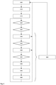
- figure 3 shows a flowchart of a method 300 for controlling motor vehicle 100 in driving cycle 200.
- motor vehicle 100 or drive train 105 is controlled in normal operation.
- a request for a special mode that is provided for controlling motor vehicle 100 on driving cycle 200 can be detected.
- the request can be made in particular by means of the operating unit 180 and is preferably implemented in such a way that unnoticed or unintentional activation is made more difficult.
- a test cycle can be selected or entered.
- step 315 it is preferably checked whether one or more starting conditions are met before method 300 continues and influences drive train 105 independently of the driver.
- a starting condition can be that motor vehicle 100 is stationary.
- Another start condition can include a successful check of the selected test cycle, for example to ensure that no acceleration or speed is specified that the motor vehicle 100 cannot reach.
- the starting condition can also be that a predetermined waiting time of a previously started fourth phase 255 has elapsed.
- a driver of the motor vehicle gives a start signal in a step 325, for example by fully actuating the accelerator pedal 160. If the accelerator pedal 160 is not fully actuated in the further course of the method 300, the drive train can be influenced independently of the driver 105 can be withdrawn immediately.
- a predetermined acceleration is to be achieved.
- Motor vehicle 100 is preferably started from a neutral position of transmission 120 (idle) without blocking the transmission. In normal operation, on the other hand, it is possible to start from an automatic neutral position (ANS) with an optional transmission block.
- the torque provided by the drive train 105 is preferably already guided along a characteristic curve from standstill (cf. lower area of figure 2 ). In this way, the predetermined target acceleration can be achieved or maintained and adjustment of a Acceleration limitation of the drive motor 110 can be reproducible in an improved manner.
- the acceleration limitation usually does not differ functionally from normal operation.
- An individual acceleration may be predetermined for each first phase 240 of a test cycle. If an engaged gear of the transmission 120 is changed, then the torque of the drive motor 110 can be specified during the shifting process.
- one or more partial load switching points can be specified individually for each first phase 240 of a driving cycle 200 in order to operate the drive motor 110 under full load as far as possible. In contrast to normal operation, these switching points can preferably also be used when accelerator pedal 160 is fully actuated.
- Such settings are usually not part of the definition of the driving cycle 200, but are selectable settings for the optimized running through of a predetermined driving cycle 200.
- the control of the drive train 105 in the first phase 240 takes place in particular taking into account the specified boundary conditions in terms of the lowest possible fuel consumption. For this purpose, a tolerance that is specified to comply with the acceleration can also be used. If a predefined condition cannot be met, method 300 can be terminated and, for example, return to first step 105 .
- a step 335 it is determined, for example on the basis of an on-board distance measurement, that motor vehicle 100 has completely driven through first route section 215 .
- the drive train 105 is controlled in the second phase 245 to the predetermined, constant speed.
- the driver still fully actuates the accelerator pedal 160.
- a preferred gear step can be specified for the second phase 245 in order to operate the drive motor 110 under full load as far as possible.
- the requirement to drive through the first phase 240 and/or the second phase 245 under full load of the drive engine 110 can be part of the definition of the driving cycle 200 .
- the control of the drive train 105 in the second phase 245 takes place taking into account the specified boundary conditions in terms of the lowest possible fuel consumption. In particular, a tolerance that is specified to maintain the speed can also be used for this purpose. If a predefined condition cannot be met, method 300 can be terminated and, for example, return to first step 105 .
- the driver can withdraw the complete actuation of the accelerator pedal 160 in order to express the desire to take over the control of the drive train 105.
- the withdrawal can take place approximately up to 10, up to 5 or up to 3 seconds before the third route section 220 is reached.
- the torque provided by the drive train 105 can be reduced independently of the driver, so that the drive motor 110 works in overrun mode.
- the driver can be prepared for the fact that he is to brake motor vehicle 100 in the following third phase 245 .
- the clutch 115 is opened and/or the transmission 120 is brought into the neutral position until the end of the second section 215 is reached.
- Such rolling without driving or decelerating the drive motor 110 is also known as coasting.
- a suitable gear in the transmission 120 is engaged in a step 350 and the clutch 15 is closed. From this, the driver receives a further indication that he should take control of the speed of motor vehicle 100 . The driver can then actuate the brake pedal 165 and decelerate the motor vehicle 105 as uniformly as possible so that it comes to a standstill at the end of the third route section 220 .
- a driver-independent control of the drive train 105 preferably no longer takes place in this step, but the drive train 105 can be controlled depending on the driver in order to support the driver and to dose or implement the deceleration. During deceleration, the gear ratio in transmission 120 can be immediately from second change gear to neutral.
- step 360 motor vehicle 100 comes to a standstill under driver control and preferably as precisely as possible at bus stop 230, and fourth phase 255, in which motor vehicle 100 stands still, begins.
- the method 300 can be run through again after the predetermined standstill time has elapsed, in particular with driving cycles 200 of different predetermined parameterizations (cf. 2 below).
- the driver can fully actuate accelerator pedal 160 again in step 360 and method 300 can branch to step 320, in which it is possible to wait for the predetermined waiting time to elapse before the next driving cycle 200 is run through.
- the driver can also decide to fully actuate accelerator pedal 160 again only after the waiting time has expired, whereupon method 300 can continue with step 320 or 325 .
- the method 300 can also terminate or return to the first step 305 .
- a step 365 carried out in parallel can be used to check whether the conditions for a valid measurement are still met. This is the case when all the conditions to be met for a valid measurement are met. If at least one condition is not met, a corresponding signal can be output, for example optically, acoustically or haptically, in particular by means of the on-board or temporarily installed operating unit 180.
- the method 300 makes it possible to control the drive train 105 of the motor vehicle 100 through a driving cycle 200 such that it is driven at least in the first phase 240 and the second phase 240 as by an ideal driver.
- the method 300 preferably does not carry out any control that could not also be provided by a human driver, so that the method 300 does not provide an unrealistic or unfair advantage when determining consumption is achieved.
- the method 300 can ensure that the driving cycle 200 or a test cycle of a plurality of successive, differently parameterized driving cycles 200 can be run with the motor vehicle 100 using as little fuel as possible. Inaccuracies or a limited repeatability of a human driver can be avoided.
Landscapes
- Engineering & Computer Science (AREA)
- Automation & Control Theory (AREA)
- Transportation (AREA)
- Mechanical Engineering (AREA)
- Human Computer Interaction (AREA)
- Electric Propulsion And Braking For Vehicles (AREA)
- Hybrid Electric Vehicles (AREA)
Description
- Die Erfindung betrifft die Steuerung eines Kraftfahrzeugs. Insbesondere betrifft die Erfindung die Durchführung eines Sonderfahrbetriebs für ein Kraftfahrzeug.
- Ein Linienbus für den innerstädtischen oder vorstädtischen Verkehr soll möglichst sparsam im Betrieb sein. Um verschiedene Busse bezüglich ihrer Kraftstoffverbräuche zu vergleichen kann jeder Bus auf einem vordefinierten Fahrzyklus gefahren und der dabei verbrauchte Kraftstoff ermittelt werden. Um ein möglichst realistisches Ergebnis zu erzielen ist ein On-Road-Test bevorzugt, bei dem der Bus tatsächlich gefahren und nicht auf einem Prüfstand stationär betrieben wird.
- Es sind zahlreiche unterschiedliche Fahrzyklen bekannt, von denen etwa 200 in T. J. Barlow, S. Latham, I. S. McCrae, P. G. Boulter: "A reference book of driving cycles for use in the measurement of road vehicle emissions", Published Project Report PPR354, TRL Limited 2009, veröffentlicht sind. Ein weiterer Fahrzyklus namens "SORT - Standardised On-Road Test Cycles" wurde 2014 vom internationalen Verband für öffentliches Verkehrswesen UITP definiert.
-
DE 10 2013 211 346 A1 schlägt vor, im Betrieb eines Kraftfahrzeugs zu bestimmen, dass ein bekanntes Fahrprofil durchfahren wird, und in Abhängigkeit des Fahrprofils eine Sonderbetriebsart des Kraftfahrzeugs durchzuführen. Die Sonderbetriebsart kann insbesondere die Steuerung eines Dieselpartikelfilters betreffen, um in einem Testbetrieb angepasste Emissionen zu bewirken. - Wird ein Kraftfahrzeug auf einem vorbestimmten Fahrzyklus durch einen menschlichen Fahrer gefahren, so können Verbrauchswerte aufgrund von Unzulänglichkeiten des Fahrers erhöht sein. Eine der vorliegenden Erfindung zu Grunde liegende Aufgabe besteht darin, eine verbesserte Steuerung des Kraftfahrzeugs beim Durchfahren des Fahrzyklus bereitzustellen. Die Erfindung löst diese Aufgabe mittels der Gegenstände der unabhängigen Ansprüche. Unteransprüche geben bevorzugte Ausführungsformen wieder.
-
EP 1 672 348 A1 schlägt ein Verfahren zum Betreiben eines Kraftfahrzeugs auf einem Rollenprüfstand vor. Auf dem Prüfstand werden vorbestimmte Fahrzyklen erfasst. Die Motorsteuerung erfolgt auf dem Prüfstand über eine externe Steuereinheit, die die Motorsteuerung ersetzt. - Ein Fahrzyklus umfasst eine erste Phase der vorbestimmten, konstanten Beschleunigung, eine zweite Phase der vorbestimmten, konstanten Geschwindigkeit, eine dritte Phase der Verzögerung und eine vierte Phase des Stillstands. Ein Verfahren zum Steuern eines Kraftfahrzeugs umfasst Schritte des Erfassens einer Auswahl eines vorbestimmten Fahrzyklus; des fahrerunabhängigen Steuerns eines Antriebsstrangs des Kraftfahrzeugs während der ersten Phase, um die vorbestimmte Beschleunigung einzuhalten; des fahrerunabhängigen Steuerns des Antriebsstrangs während der zweiten Phase, um die vorbestimmte Geschwindigkeit einzuhalten; und des Erfassens einer fahrergesteuerten Verzögerung des Kraftfahrzeugs.
- Mehrere aufeinander folgende Fahrzyklen können einen SORT-Testzyklus bilden, der zur Beurteilung eines Kraftstoffverbrauchs durch ein Kraftfahrzeug, insbesondere ein Nutzfahrzeug, weiter bevorzugt eines Stadt- oder Linienbusses verwendet werden kann. Das Verfahren ermöglicht es, das Kraftfahrzeug optimiert durch den Fahrzyklus zu fahren. Die Auswahl eines Testzyklus erfolgt bevorzugt manuell, wobei eine Abfolge von Fahrzyklen innerhalb des Testzyklus bevorzugt bereits festgelegt ist und automatisch abgearbeitet werden kann. Es kann eine Vielzahl von Testzyklen durchfahren werden, um die Bildung eines statistischen Mittelwerts des Kraftstoffverbrauchs zu erlauben.
- Ziel des Verfahrens ist, ein vordefiniertes Testszenario möglichst präzise so zu durchfahren, dass Vorgaben für eine gültige Messung erfüllt sind und gleichzeitig ein Kraftstoffverbrauch des Kraftfahrzeugs möglichst minimiert ist. Das Verfahren soll einen idealen Fahrer simulieren, um menschliche Unvollkommenheiten bei der Testfahrt möglichst auszuschalten. Ein Vorteil gegenüber einem optimal sachkundigen und geübten Fahrer soll dabei nicht erzielt werden, sodass das Ergebnis der Messung verbessert aussagekräftig sein kann.
- Es ist bevorzugt, dass die fahrerunabhängige Steuerung der ersten und zweiten Phase durchgeführt wird, während ein Fahrpedal zur Beschleunigungssteuerung des Kraftfahrzeugs vollständig betätigt ist. Die Kontrolle über den Antriebsstrang kann durch das vollständige Betätigen des Fahrpedals vom Fahrer auf das Verfahren übertragen werden. Eine Rückübertragung der Kontrolle kann durch eine verringerte Betätigung des Fahrpedals bewirkt werden. Der Testbetrieb kann so rasch und auf intuitive Weise abgebrochen werden, sodass eine Fahrsicherheit gesteigert sein kann. Das vollständige Betätigen des Fahrpedals kann als Signal verstanden werden, dass die Steuerung des Antriebsstrangs nicht mehr durch den Fahrer sondern durch eine Steuervorrichtung bzw. ein darauf ablaufendes Verfahren durchgeführt wird. Außerdem kann so zusätzlich sichergestellt werden, dass das Verfahren nicht versehentlich oder unbemerkt, etwa im Rahmen eines üblichen Fahrbetriebs, durchgeführt wird. Es können noch weitere Bedingungen vorgegeben sein, um die fahrerunabhängige Steuerung einzuleiten oder aufrecht zu erhalten.
- Der Antriebsstrang umfasst üblicherweise einen Antriebsmotor, eine Kupplung und ein Getriebe. Es ist bevorzugt, dass in der ersten oder zweiten Phase wenigstens eines der Elemente des Antriebsstrangs derart gesteuert wird, dass ein Kraftstoffverbrauch des Antriebsmotors möglichst minimiert ist. Dabei können weitere Randbedingungen, die zum korrekten oder vorteilhaften Befahren des Fahrzyklus vorgegeben sind, eingehalten werden, beispielsweise ein vorbestimmter Gang, ein vorbestimmter Schaltpunkt oder ein vorbestimmter Lastpunkt des Antriebsmotors.
- Ein gültiges Durchfahren des Fahrzyklus kann ein Einhalten vorbestimmter Bewegungsparameter durch das Kraftfahrzeug umfassen, wobei der Antriebsstrang in der ersten und zweiten Phase derart gesteuert wird, dass der Kraftstoffverbrauch des Antriebsmotors möglichst minimiert ist. Insbesondere können Toleranzen, die dem Bewegungsparameter aufgeschlagen werden dürfen, ausgenutzt werden. Soll etwa in der zweiten Phase eine Geschwindigkeit von 30 km/h gefahren werden und ist eine Messung nur gültig, falls die tatsächlich gefahrene Geschwindigkeit um nicht mehr als ±0,5 km/h davon abweicht, so kann der Antriebsstrang des Kraftfahrzeugs derart gesteuert werden, dass die Geschwindigkeit über einen möglichst großen Anteil der zweiten Phase 29,5 km/h beträgt. Es sind auch weitere Gültigkeits- bzw. Ungültigkeitsbedingungen möglich um die Vergleichbarkeit der Messungen sicher zu stellen. In einer Ausführungsform wird ein Signal ausgegeben, falls eine der Gültigkeitsbedingungen verletzt wird, sodass die Messfahrt vorzeitig abgebrochen oder wiederholt werden kann.
- Die zweite Phase kann beendet sein, wenn das Kraftfahrzeug eine vorbestimmte Strecke gefahren ist. In einer Ausführungsform wird an einem vorbestimmten Punkt bereits vor dem Ende der zweiten Phase der Antriebsmotor angesteuert, sein abgegebenes Antriebsmoment zu verringern. Der vorbestimmte Punkt kann als Zeitpunkt, insbesondere bezüglich des Beginns der zweiten Phase, oder als Ortspunkt, insbesondere bezüglich des Punkts, an dem sich das Kraftfahrzeug bei Eintritt in die zweite Phase befand, definiert sein. Durch das Rücknehmen des Antriebsmoments kann dem Fahrer signalisiert werden, dass eine Übernahme der Kontrolle über den Antriebsstrang durch ihn für die dritte Phase bevorsteht. Anstelle der Verringerung des Antriebsmoments kann der Antriebsmotor vom Antriebsstrang abgekoppelt werden, etwa durch Öffnen der Kupplung oder Einlegen einer Neutralstellung (Leerlauf) im Getriebe. Bis zum Ende der zweiten Phase kann dann ein sogenanntes Segeln erfolgen, durch das weiterer Kraftstoff eingespart werden kann.
- Es ist besonderes bevorzugt, dass der Antriebsstrang ein Getriebe mit Differenzwandler umfasst. Der Differenzwandler umfasst eine Kombination aus einem Umlaufgetriebe, einem hydrodynamischen Drehmomentwandler und üblicherweise noch einem Schaltgetriebe. Der Differenzwandler kann beim Anfahren des Kraftfahrzeugs Drehmoment mittels eines formschlüssigen Radsatzes des Getriebes und gleichzeitig mittels des Drehmomentwandlers übertragen, wobei ein Momentenverhältnis zwischen Radsatz und Drehmomentwandler stufenlos veränderlich sein kann. Insbesondere ist das Momentenverhältnis bevorzugt von einer Drehzahl der Ausgangsseite des Getriebes abhängig. Der Differenzwandler kann verbessert mittels des oben beschriebenen Verfahrens angesteuert werden, um das Kraftfahrzeug optimiert durch den Fahrzyklus zu steuern.
- In einer Weiterbildung des Verfahrens kann das fahrergesteuerte Verzögern in der dritten Phase fahrerunabhängig unterstützt werden. Beispielsweise kann ein direkter Übergang von einer zweiten Gangstufe in eine Neutralstellung erfolgen statt wie üblich ein Übergang von der zweiten Gangstufe zunächst in die erste Gangstufe. In einer weiteren Ausführungsform kann der Verzögerungsvorgang durch eine Retarderfunktionalität des Drehmomentwandlers unterstützt werden.
- Ein Computerprogrammprodukt umfasst Programmcodemittel zur Durchführung des oben beschriebenen Verfahrens, wenn das Computerprogrammprodukt auf einer Verarbeitungseinrichtung abläuft oder auf einem computerlesbaren Datenträger gespeichert ist. Die Verarbeitungseinrichtung kann insbesondere einen programmierbaren Mikrocomputer umfassen.
- Beispielhafte Ausführungsformen der Erfindung werden nun mit Bezug auf die beigefügten Figuren genauer beschrieben, in denen:
- Fig. 1
- eine schematische Darstellung eines Kraftfahrzeugs;
- Fig. 2
- einen beispielhaften Fahrzyklus für ein Kraftfahrzeug; und
- Fig. 3
- ein Ablaufdiagramm eines Verfahrens zum Steuern eines Kraftfahrzeugs
-
Figur 1 zeigt ein Kraftfahrzeug 100, insbesondere ein Nutzfahrzeug, weiter bevorzugt einen Bus, beispielsweise einen Stadtbus, in einer schematischen Darstellung. Das Kraftfahrzeug 100 umfasst einen Antriebsstrang 105, der einen Antriebsmotor 110, eine Kupplung 115, ein Getriebe 120, ein Differentialgetriebe 125 und ein Antriebsrad 130 umfassen kann. Der Antriebsmotor 110 ist üblicherweise ein Otto- oder Dieselmotor und benötigt zum Betrieb einen Kraftstoff als Energieträger. In einer anderen Ausführungsform kann der Antriebsmotor 110 auch einen anderen Motor wie einen Elektromotor umfassen, der elektrische Energie verwendet, die im Sinne der Anmeldung ebenfalls als Kraftstoff begriffen werden kann. - In der vorliegenden, bevorzugten Ausführungsform ist das Getriebe 120 als Differenzialwandler ("DIWA") ausgeführt, der mit der Kupplung 115 funktional integriert sein kann. Der Differenzialwandler umfasst üblicherweise ein Umlaufgetriebe mit einer Eingangsseite, einer Zwischenseite und einer Ausgangsseite, sowie einen hydrodynamischen Drehmomentwandler mit einem Pumpenrad und einem Turbinenrad, die mittels eines Fluids hydrodynamisch miteinander gekoppelt sind. Die Eingangs- bzw. Ausgangsseite des Umlaufgetriebes bildet auch die Eingangs- bzw. Ausgangsseite des Getriebes 120. Die Zwischenseite des Umlaufgetriebes ist mit dem Pumpenrad verbunden und das Turbinenrad wirkt bevorzugt über einen Freilauf auf die Ausgangsseite. Zum Anfahren des Kraftfahrzeugs arbeitet das Umlaufgetriebe im Dreiwellenbetrieb und das Untersetzungsverhältnis des Umlaufgetriebes ist von einer Drehzahl des Drehmomentwandlers abhängig. Das Getriebe 120 überträgt Drehmoment parallel durch das Umlaufgetriebe und den Drehmomentwandler, wobei ein Verhältnis der übertragenen Momente von einer Drehzahl der Ausgangsseite abhängig ist. Bei höherer Drehzahl kann die Zwischenseite auf eine Drehzahl von null abgebremst bzw. festgestellt werden, sodass das Umlaufgetriebe in den Zweiwellenbetrieb übergeht. Der Freilauf zwischen dem Turbinenrad und der Ausgangsseite kann dabei den Drehmomentwandler von der Ausgangsseite abkoppeln. Das Drehmoment wird dann nur noch mittels des Umlaufgetriebes übertragen. Bevorzugt ist zwischen der Ausgangsseite und dem Differentialgetriebe 125 noch ein Schaltgetriebe vorgesehen. Der Differenzialwandler kann auch angesteuert werden, als Retarder zu arbeiten, wobei Bewegungsenergie der Ausgangsseite in eine Erwärmung des Fluids des Drehmomentwandlers umgesetzt wird.
- Eine Steuervorrichtung 150 ist dazu eingerichtet, das Getriebe 120 zu steuern. Dabei kann auch Einfluss auf den Antriebsmotor 110 genommen werden, beispielsweise indem ein Drehmoment, das der Antriebsmotor 110 zur Verfügung stellt, begrenzt bzw. reduziert wird. Auch die Kupplung 115, die als Reibscheibenkupplung ausgeführt sein kann, kann durch die Steuervorrichtung 150 geöffnet oder geschlossen werden. Ein Schlupfbetrieb kann ebenfalls möglich sein.
- Die Steuervorrichtung 150 ist bevorzugt mit einer ersten Abtasteinrichtung 155 zur Abtastung der Stellung eines Fahrpedals 160 verbunden, das durch einen Fahrer des Kraftfahrzeugs 105 betätigt werden kann, um ein durch den Antriebsmotor 110 bzw. den Antriebsstrang 105 bereitgestelltes Drehmoment zu steuern. Eine zweite Abtasteinrichtung 165 zur Abtastung einer Betätigung eines Bremspedals 170 kann ebenfalls mit der Steuervorrichtung 150 verbunden sein. Das Bremspedal 170 ist zur Betätigung einer Bremseinrichtung (nicht dargestellt) vorgesehen, wobei die Bremseinrichtung eine Betriebsbremse, einen Retarder oder einen Rekuperator umfassen kann, die auch in Kombination angesteuert werden können.
- Bevorzugt ist eine Schnittstelle 175 zur Übertragung von Steuerparametern mit der Steuervorrichtung 150 verbunden. Die Schnittstelle 175 kann insbesondere einen Anschluss an einen fahrzeuginternen Datenbus, etwa einen CAN-Bus, ermöglichen. Signale der Abtasteinrichtungen 165, 170 oder Steuer- oder Betriebsparameter des Antriebsmotors 110 können über den Datenbus übermittelt werden. Eine Bedieneinheit 180 kann mit der Steuervorrichtung 150 verbunden sein oder über die Schnittstelle 175 temporär mit der Steuervorrichtung 150 verbunden werden. In beiden Varianten kann die Steuervorrichtung 150 eine Eingabe und/oder Ausgabe von Parametern der Steuervorrichtung 150 erlauben.
- Die Steuervorrichtung 150 ist dazu eingerichtet, den Antriebsstrang 105 beim Durchfahren eines vorbestimmten Fahrzyklus, und bevorzugt auch in einem Normalbetrieb, zu steuern. Parameter des Fahrzyklus können in einem Speicher 185 abgelegt sein und mittels der Bedieneinheit 180 ausgewählt werden. Alternativ können die Parameter auch unmittelbar mittels der Bedieneinheit 180 eingegeben werden, beispielsweise als Datensatz. Die Steuervorrichtung soll den Fahrer beim Durchfahren des vorbestimmten Fahrzyklus unterstützen, um möglichst geringe Verbrauchswerte von Kraftstoff durch den Antriebsmotor 110 zu erzielen.
-
Figur 2 zeigt einen Fahrzyklus 200 für das Kraftfahrzeug 100 ausFigur 1 nach Art eines SORT-Fahrzyklus der UITP. In einer oberen Darstellung ist eine Strecke 205 mit einem ersten Streckenabschnitt 210, einem zweitem Streckenabschnitt 215 und einem dritten Streckenabschnitt 220 dargestellt. Am Ende des dritten Streckenabschnitts 220 ist eine Haltestelle 225 vorgesehen. Zwischen den Streckenabschnitten 210, 215 und 220 sind zur Veranschaulichung Pylone 230 eingezeichnet; diese werden bei einer realen Durchführung des Fahrzyklus 200 üblicherweise tatsächlich als Orientierung für den Fahrer des Kraftfahrzeugs 100 an der Strecke 205 aufgestellt. - In einem unteren Bereich von
Figur 2 ist eine exemplarische Parametrierung des Fahrzyklus dargestellt. Das gezeigte Beispiel entspricht im Wesentlichen der Vorgabe "Heavy Urban" des SORT. In einem linken Bereich ist eine Geschwindigkeit (vertikal) über einem Weg (horizontal) auf der Strecke 205 und in einem rechten Bereich eine Geschwindigkeit (vertikal) über einer Zeit (horizontal) dargestellt, wobei beide Darstellungen den gleichen Sachverhalt betreffen. Beide Darstellungen umfassen je drei Fahrzyklen 200, die üblicherweise zusammen einen vorbestimmten Testzyklus bilden. Die zeitliche Reihenfolge der drei Fahrzyklen 200 ist dabei festgelegt und bei der Durchführung wird üblicherweise stets ein kompletter Testzyklus durchfahren, bevorzugt mehrfach hintereinander. Wie die einzelnen Fahrzyklen 200 dabei genau parametriert sind, also an welchen Stellen auf der Strecke 205 bzw. nach welcher Zeit eine Phase 240 bis 255 beginnt oder endet, sowie welche fahrdynamischen Parameter (z. B. Beschleunigung oder Geschwindigkeit des Kraftfahrzeugs 100) zu erbringen sind, kann von einem konkreten Anwendungsfall abhängen. - Jeder Fahrzyklus 200 umfasst bevorzugt eine erste Phase 240 der konstanten Beschleunigung, eine zweite Phase 245 der konstanten Geschwindigkeit, eine dritte Phase 250 der Verzögerung und eine vierte Phase 255 des Stillstands des Kraftfahrzeugs 100. Die Phasen 240 bis 255 korrespondieren paarweise zu den Streckenabschnitten 210 bis 220 und die vierte Phase 255 korrespondiert zur Haltestelle 225. Übergänge zwischen den Phasen 240 bis 250 sind bezüglich bestimmter Wegpunkte auf der Strecke 205 bestimmt, die Phase 255, in der das Kraftfahrzeug 100 stillsteht, ist bezüglich einer Zeit definiert. Außerdem können noch weitere Bedingungen definiert sein, die eine gültige Messung erfordert, etwa ein Schaltschema für Gänge des Getriebes 120 oder eine maximal zulässige Abweichung der Beschleunigung, Geschwindigkeit oder Wartezeit des Kraftfahrzeugs 100 von vorgegebenen Werten.
-
Figur 3 zeigt ein Ablaufdiagramm eines Verfahrens 300 zum Steuern des Kraftfahrzeugs 100 auf dem Fahrzyklus 200. In einem optionalen Schritt 305 wird das Kraftfahrzeug 100 bzw. der Antriebsstrang 105 in einem Normalbetrieb gesteuert. In einem Schritt 310 kann eine Anforderung für einen Sonderbetrieb erfasst werden, der zur Steuerung des Kraftfahrzeugs 100 auf dem Fahrzyklus 200 vorgesehen ist. Die Anforderung kann insbesondere mittels der Bedieneinheit 180 gegeben werden und ist bevorzugt so ausgeführt, dass eine unbemerkte oder unbeabsichtigte Aktivierung erschwert ist. In einem Schritt 315 kann ein Testzyklus ausgewählt oder eingegeben werden. - Bevorzugt wird in einem Schritt 315 überprüft, ob eine oder mehrere Startbedingungen erfüllt sind, bevor das Verfahren 300 fortfährt und den Antriebsstrang 105 fahrerunabhängig beeinflusst. Eine Startbedingung kann lauten, dass das Kraftfahrzeug 100 stillsteht. Eine andere Startbedingung kann eine erfolgreiche Überprüfung des ausgewählten Testzyklus umfassen, um beispielsweise sicher zu stellen, dass keine Beschleunigung oder Geschwindigkeit vorgegeben ist, die das Kraftfahrzeug 100 nicht erreichen kann. Insbesondere wenn ein Fahrzyklus mehrfach hintereinander durchfahren wird, kann außerdem als Startbedingung gelten, dass eine vorbestimmte Wartezeit einer zuvor begonnenen vierten Phase 255 abgelaufen ist. Um fortzufahren ist außerdem bevorzugt, dass ein Fahrer des Kraftfahrzeugs in einem Schritt 325 ein Startsignal gibt, beispielsweise durch das vollständige Betätigen des Fahrpedals 160. Bleibt die vollständige Betätigung des Fahrpedals 160 im weiteren Verlauf des Verfahrens 300 aus, so kann eine fahrerunabhängige Beeinflussung des Antriebsstrangs 105 sofort zurückgenommen werden.
- In einem Schritt 330 wird das Fahren des Kraftfahrzeugs 100 in der ersten Phase 240 gesteuert, eine vorbestimmte Beschleunigung zu erbringen ist. Das Anfahren des Kraftfahrzeugs 100 erfolgt bevorzugt aus einer Neutralstellung des Getriebes 120 (Leerlauf) ohne Getriebeblockierung. In einem Normalbetrieb hingegen kann bevorzugt aus einer automatischen Neutralstellung (ANS) mit optionaler Getriebeblockierung heraus angefahren werden. Das durch den Antriebsstrang 105 bereitgestellte Drehmoment wird vorzugsweise bereits ab dem Stillstand entlang einer Kennlinie geführt (vgl. unteren Bereich von
Figur 2 ). So kann die vorbestimmte Sollbeschleunigung erreicht bzw. eingehalten werden und ein Einregeln einer Beschleunigungslimitierung des Antriebsmotors 110 kann verbessert reproduzierbar sein. Die Beschleunigungslimitierung unterscheidet üblicherweise sich funktional nicht vom Normalbetrieb. - Für jede erste Phase 240 eines Testzyklus kann eine individuelle Beschleunigung vorbestimmt sein. Wird eine eingelegte Gangstufe des Getriebes 120 gewechselt, so kann das Drehmoment des Antriebsmotors 110 während des Schaltvorgangs vorgegeben werden. Außerdem können einer oder mehrere Teillast-Schaltpunkte individuell für jede erste Phase 240 eines Fahrzyklus 200 vorgegeben werden, um den Antriebsmotor 110 möglichst unter Volllast zu betreiben. Diese Schaltpunkte können, anders als im Normalbetrieb, bevorzugt auch bei vollständig betätigtem Fahrpedal 160 verwendet werden. Derartige Einstellungen sind üblicherweise nicht Bestandteil der Definition des Fahrzyklus 200, sondern es handelt sich um wählbare Einstellungen für das optimierte Durchfahren eines vorbestimmten Fahrzyklus 200.
- Die Steuerung des Antriebsstrangs 105 in der ersten Phase 240 erfolgt insbesondere unter Beachtung der vorgegebenen Randbedingungen im Sinne eines möglichst geringen Kraftstoffverbrauchs. Dazu kann eine Toleranz, die zur Einhaltung der Beschleunigung vorgegeben ist, mit ausgenutzt werden. Kann eine vorgegebene Bedingung nicht erfüllt werden, so kann das Verfahren 300 abbrechen und beispielsweise in den ersten Schritt 105 zurückkehren.
- In einem Schritt 335 wird bestimmt, etwa auf der Basis einer bordeigenen Wegstreckenmessung, dass das Kraftfahrzeug 100 den ersten Streckenabschnitt 215 vollständig durchfahren hat. Optional kann zusätzlich bestimmt werden, dass die für die zweite Phase 245 vorbestimmte Geschwindigkeit erreicht wurde. Ab einem Schritt 340 wird der Antriebsstrang 105 in der zweiten Phase 245 auf die vorbestimmte, konstante Geschwindigkeit gesteuert. In einer bevorzugten Ausführungsform betätigt der Fahrer dabei immer noch vollständig das Fahrpedal 160. Für die zweite Phase 245 kann eine bevorzugte Gangstufe vorgegeben werden, um den Antriebsmotor 110 möglichst unter Volllast zu betreiben. Die Anforderung, die erste Phase 240 und/oder die zweite Phase 245 unter Volllast des Antriebsmotors 110 zu durchfahren, kann Teil der Definition des Fahrzyklus 200 sein.
- Die Steuerung des Antriebsstrangs 105 in der zweiten Phase 245 erfolgt unter Beachtung der vorgegebenen Randbedingungen im Sinne eines möglichst geringen Kraftstoffverbrauchs. Dazu kann insbesondere eine Toleranz, die zur Einhaltung der Geschwindigkeit vorgegeben ist, mit ausgenutzt werden. Kann eine vorgegebene Bedingung nicht erfüllt werden, so kann das Verfahren 300 abbrechen und beispielsweise in den ersten Schritt 105 zurückkehren.
- Möglichst kurz vor dem Erreichen des Endes des zweiten Streckenabschnitts 215 kann der Fahrer die vollständige Betätigung des Fahrpedals 160 zurücknehmen, um den Wunsch nach einer Übernahme der Steuerung des Antriebsstrangs 105 auszudrücken. Die Rücknahme kann etwa bis zu 10, bis zu 5 oder bis zu 3 Sekunden vor dem Erreichen des dritten Streckenabschnitts 220 erfolgen.
- In einem vorbestimmten Abstand vor dem Ende des zweiten Streckenabschnitts 215, ausgedrückt als Entfernung oder als Zeit vor dem Erreichen bei der vorbestimmten Geschwindigkeit, kann das durch den Antriebsstrang 105 bereitgestellte Drehmoment fahrerunabhängig reduziert werden, sodass der Antriebsmotor 110 im Schiebebetrieb arbeitet. Dadurch kann der Fahrer darauf vorbereitet werden, dass er das Kraftfahrzeug 100 in der folgenden dritten Phase 245 abbremsen soll. In einer anderen Ausführungsform wird bis zum Erreichen des Endes des zweiten Streckenabschnitts 215 die Kupplung 115 geöffnet und/oder das Getriebe 120 in die Neutralstellung gebracht. Ein derartiges Rollen ohne Antrieb oder Verzögerung des Antriebsmotors 110 ist auch als Segeln bekannt.
- Mit dem Eintreten in die dritte Phase 250 wird, falls dies nicht bereits erfolgt ist, in einem Schritt 350 eine passende Gangstufe im Getriebe 120 eingelegt und die Kupplung 15 geschlossen. Der Fahrer erhält daraus einen weiteren Hinweis, dass er die Kontrolle über die Geschwindigkeit des Kraftfahrzeugs 100 übernehmen soll. Der Fahrer kann dann das Bremspedal 165 betätigen und das Kraftfahrzeug 105 möglichst gleichmäßig so verzögern, dass es am Ende des dritten Streckenabschnitts 220 zum Stillstand kommt. Eine fahrerunabhängige Steuerung des Antriebsstrangs 105 findet in diesem Schritt bevorzugt nicht mehr statt, jedoch kann der Antriebsstrang 105 fahrerabhängig gesteuert werden, um den Fahrer zu unterstützen und die Verzögerung zu dosieren bzw. realisieren. Während des Verzögerns kann die Gangstufe im Getriebe 120 unmittelbar vom zweiten Gang in die Neutralstellung gewechselt werden. Im Normalbetrieb wäre hingegen bevorzugt, die Kupplung 115 zu öffnen statt die Neutralstellung einzulegen. Durch die Neutralstellung kann sichergestellt werden, dass das Kraftfahrzeug 100 auch bei nur geringer Betätigung des Bremspedals 170 sicher zum Stillstand kommt und auch in diesem verbleibt. Außerdem kann verhindert werden, dass aufgrund einer anderen Logik die Kupplung 115 geschlossen wird, während ein Gang im Getriebe 120 eingelegt ist.
- In einem Schritt 360 kommt das Kraftfahrzeug 100 fahrergesteuert und bevorzugt möglichst genau an der Haltestelle 230 zum Stehen und die vierte Phase 255, in der das Kraftfahrzeug 100 stillsteht, beginnt. Das Verfahren 300 kann nach Ablauf der vorbestimmten Stillstandszeit erneut durchlaufen werden, insbesondere mit Fahrzyklen 200 unterschiedlicher vorbestimmter Parametrierungen (vgl.
Fig. 2 unten). Der Fahrer kann das Fahrpedal 160 bereits im Schritt 360 wieder vollständig betätigen und das Verfahren 300 kann in den in Schritt 320 verzweigen, in dem das Verstreichen der vorbestimmten Wartezeit abgewartet werden kann, bevor der nächste Fahrzyklus 200 durchfahren wird. Der Fahrer kann sich auch entscheiden, das Fahrpedal 160 erst nach Ablauf der Wartezeit wieder vollständig zu betätigen, worauf das Verfahren 300 mit dem Schritt 320 oder 325 fortfahren kann. Das Verfahren 300 kann aber auch terminieren oder zum ersten Schritt 305 zurückkehren. - Insbesondere während der Schritte 330 bis 360 kann in einem parallel durchgeführten Schritt 365 überprüft werden, ob noch die Bedingungen für eine gültige Messung erfüllt sind. Dies ist der Fall, wenn alle für eine gültige Messung zu erfüllenden Bedingungen eingehalten sind. Ist wenigstens eine Bedingung nicht erfüllt, so kann ein entsprechendes Signal ausgegeben werden, beispielsweise optisch, akustisch oder haptisch, insbesondere mittels der bordeigenen oder temporär angebrachten Bedieneinheit 180.
- Das Verfahren 300 ermöglicht es, den Antriebsstrang 105 des Kraftfahrzeugs 100 derart durch einen Fahrzyklus 200 zu steuern, dass es zumindest in der ersten Phase 240 und der zweiten Phase 240 wie von einem idealen Fahrer gefahren wird. Das Verfahren 300 führt bevorzugt keine Steuerung durch, die nicht auch von einem menschlichen Fahrer erbracht werden könnte, sodass durch das Verfahren 300 kein unrealistischer oder unfairer Vorteil bei der Verbrauchsbestimmung erzielt wird. Das Verfahren 300 kann sicher stellen, dass der Fahrzyklus 200 bzw. ein Testzyklus von mehreren aufeinander folgenden, unterschiedlich parametrisierten Fahrzyklen 200, unter Aufwand von möglichst wenig Kraftstoff mit dem Kraftfahrzeug 100 befahren werden kann. Ungenauigkeiten oder eine begrenzte Wiederholgenauigkeit eines menschlichen Fahrers können vermieden werden.
-
- 100
- Kraftfahrzeug
- 105
- Antriebsstrang
- 110
- Antriebsmotor
- 115
- Kupplung
- 120
- Getriebe
- 125
- Differentialgetriebe
- 130
- Antriebsrad
- 150
- Steuervorrichtung
- 155
- erste Abtasteinrichtung
- 160
- Fahrpedal
- 165
- zweite Abtasteinrichtung
- 170
- Bremspedal
- 175
- Schnittstelle
- 180
- Bedieneinheit
- 185
- Speicher
- 200
- Fahrzyklus
- 205
- Strecke
- 210
- erster Streckenabschnitt
- 215
- zweiter Streckenabschnitt
- 220
- dritter Streckenabschnitt
- 225
- Haltestelle
- 230
- Pylon
- 240
- erste Phase (Beschleunigung)
- 245
- zweite Phase (Konstantfahrt)
- 250
- dritte Phase (Verzögerung)
- 255
- vierte Phase (Stillstand)
- 300
- Verfahren
- 305
- Normalbetrieb
- 310
- Erfassen Anforderung
- 315
- Auswählen SORT-Zyklus
- 320
- Startbedingungen erfüllt?
- 325
- Losfahrbedingung erfüllt?
- 330
- Phase 1: Steuerung auf vorbestimmte Beschleunigung
- 335
- ersten Streckenabschnitt durchfahren?
- 340
- Phase 2: Steuerung auf vorbestimmte Geschwindigkeit
- 345
- zweiten Streckenabschnitt durchfahren?
- 350
- Übergabe an Fahrer
- 355
- Phase 3: Verzögerung. Unterstützen
- 360
- Phase 4: Stillstand
- 365
- Hinweis, falls Messung ungültig
Claims (9)
- Verfahren (300) zum Steuern eines Kraftfahrzeugs (100) mit einem Antriebsstrang (105), wobei das Verfahren (300) folgende Schritte umfasst:- Erfassen einer Auswahl eines vorbestimmten Fahrzyklus (200), wobei der Fahrzyklus (200) eine erste Phase (240) der vorbestimmten, konstanten Beschleunigung, eine zweite Phase (245) der vorbestimmten, konstanten Geschwindigkeit, eine dritte Phase (250) der Verzögerung und eine vierte Phase (255) des Stillstands umfasst;- fahrerunabhängiges Steuern des Antriebsstrangs (105) während der ersten Phase (240), um die vorbestimmte Beschleunigung einzuhalten;- fahrerunabhängiges Steuern des Antriebsstrangs (105) während der zweiten Phase (245), um die vorbestimmte Geschwindigkeit einzuhalten; und- Erfassen einer fahrergesteuerten Verzögerung des Kraftfahrzeugs (100).
- Verfahren (300) nach Anspruch 1, wobei die fahrerunabhängige Steuerung der ersten (240) und zweiten Phase (245) durchgeführt wird, während ein Fahrpedal (160) zur Beschleunigungssteuerung des Kraftfahrzeugs (100) vollständig betätigt ist.
- Verfahren (300) nach Anspruch 1 oder 2, wobei der Antriebsstrang (105) einen Antriebsmotor (110), eine Kupplung (115) und ein Getriebe (120) umfasst und wenigstens ein Element des Antriebsstrangs (105) in der ersten (240) oder zweiten Phase (245) derart gesteuert wird, dass ein Kraftstoffverbrauch des Antriebsmotors (110) möglichst minimiert ist.
- Verfahren (300) nach einem der vorangehenden Ansprüche, wobei ein gültiges Durchfahren des Fahrzyklus (200) ein Einhalten vorbestimmter Bewegungsparameter durch das Kraftfahrzeug (100) umfasst und der Antriebsstrang (105) in der ersten (240) und zweiten Phase (245) derart gesteuert wird, dass der Kraftstoffverbrauch eines Antriebsmotors (110) des Antriebsstrangs (105) möglichst minimiert ist.
- Verfahren (300) nach einem der vorangehenden Ansprüche, wobei die zweite Phase (245) beendet ist, wenn das Kraftfahrzeug (100) eine vorbestimmte Strecke gefahren ist und wobei vor dem Ende der zweiten Phase (245) ein Antriebsmotor (110) des Antriebsstrangs (105) angesteuert wird, sein abgegebenes Antriebsmoment zu verringern.
- Verfahren (300) nach Anspruch 5, wobei gleichzeitig eine Kupplung (115) des Antriebsstrangs (105) geöffnet oder ein Getriebe (120) des Antriebsstrangs (105) in eine Neutralstellung gebracht wird.
- Verfahren (300) nach einem der vorangehenden Ansprüche, wobei der Antriebsstrang (105) ein Getriebe (120) mit Differenzwandler umfasst.
- Verfahren (300) nach einem der vorangehenden Ansprüche, wobei das fahrergesteuerte Verzögern in der dritten Phase (250) fahrerunabhängig unterstützt wird.
- Computerprogrammprodukt mit Programmcodemitteln zur Durchführung des Verfahrens (300) nach einem der vorangehenden Ansprüche, wenn das Computerprogrammprodukt auf einer Verarbeitungseinrichtung abläuft oder auf einem computerlesbaren Datenträger gespeichert ist.
Priority Applications (1)
| Application Number | Priority Date | Filing Date | Title |
|---|---|---|---|
| PL17751033T PL3500468T3 (pl) | 2016-08-18 | 2017-07-19 | Sterowanie pojazdem użytkowym |
Applications Claiming Priority (2)
| Application Number | Priority Date | Filing Date | Title |
|---|---|---|---|
| DE102016215431.1A DE102016215431A1 (de) | 2016-08-18 | 2016-08-18 | Steuerung eines Nutzfahrzeugs |
| PCT/EP2017/068173 WO2018033331A1 (de) | 2016-08-18 | 2017-07-19 | Steuerung eines nutzfahrzeugs |
Publications (2)
| Publication Number | Publication Date |
|---|---|
| EP3500468A1 EP3500468A1 (de) | 2019-06-26 |
| EP3500468B1 true EP3500468B1 (de) | 2022-02-23 |
Family
ID=59579598
Family Applications (1)
| Application Number | Title | Priority Date | Filing Date |
|---|---|---|---|
| EP17751033.6A Not-in-force EP3500468B1 (de) | 2016-08-18 | 2017-07-19 | Steuerung eines nutzfahrzeugs |
Country Status (4)
| Country | Link |
|---|---|
| EP (1) | EP3500468B1 (de) |
| DE (1) | DE102016215431A1 (de) |
| PL (1) | PL3500468T3 (de) |
| WO (1) | WO2018033331A1 (de) |
Family Cites Families (5)
| Publication number | Priority date | Publication date | Assignee | Title |
|---|---|---|---|---|
| DE10051353A1 (de) * | 2000-10-17 | 2002-04-18 | Daimler Chrysler Ag | Verfahren zur Vorgabe eines Fahrpedalsollwertes |
| EP1672348A1 (de) * | 2004-12-14 | 2006-06-21 | Ford Global Technologies, LLC, A subsidary of Ford Motor Company | Verfahren zum Betreiben eines Kraftfahrzeuges auf einem Rollenprüfstand |
| DE102005044271A1 (de) * | 2005-09-16 | 2007-03-29 | Robert Bosch Gmbh | Verfahren und Vorrichtung zur Geschwindigkeitsregelung eines Kraftfahrzeuges |
| DE102013211346A1 (de) | 2013-06-18 | 2014-12-18 | Robert Bosch Gmbh | Verfahren zur Durchführung einer Sonderbetriebsart für ein Kraftfahrzeug |
| SE539688C2 (en) * | 2014-12-05 | 2017-10-31 | Scania Cv Ab | Apparatus and method for controlling a velocity of a bus |
-
2016
- 2016-08-18 DE DE102016215431.1A patent/DE102016215431A1/de not_active Withdrawn
-
2017
- 2017-07-19 WO PCT/EP2017/068173 patent/WO2018033331A1/de not_active Ceased
- 2017-07-19 PL PL17751033T patent/PL3500468T3/pl unknown
- 2017-07-19 EP EP17751033.6A patent/EP3500468B1/de not_active Not-in-force
Also Published As
| Publication number | Publication date |
|---|---|
| WO2018033331A1 (de) | 2018-02-22 |
| PL3500468T3 (pl) | 2022-06-20 |
| DE102016215431A1 (de) | 2018-02-22 |
| EP3500468A1 (de) | 2019-06-26 |
Similar Documents
| Publication | Publication Date | Title |
|---|---|---|
| DE69309003T2 (de) | Steuerung für Betriebsarten einer Kupplung | |
| DE10307462B4 (de) | Verfahren zur Steuerung der Antriebseinheit eines Fahrzeugs | |
| DE102010060079B4 (de) | Verfahren und Steuerungssystem zum Öffnen des Antriebsstrangs eines Kraftfahrzeuges | |
| DE19916637C1 (de) | Verfahren zum Steuern des Antriebsstrangs eines Kraftfahrzeugs und Antriebsstrangsteuerung eines Kraftfahrzeugs | |
| DE102009046340A1 (de) | Verfahren zur Steuerung einer Roll- oder Segelfunktion eines Fahrzeugs | |
| DE102011008363A1 (de) | Anfahrkupplungsschutz auf einer Neigung bei Fahrzeugstart | |
| WO2017108309A1 (de) | Verfahren zum betreiben eines kraftfahrzeugs durch kriechbetrieb der kupplung | |
| EP2788231B1 (de) | Abkoppelbarer hydrodynamischer retarder und steuerungsverfahren hierfür | |
| WO2017182384A1 (de) | Verfahren und steuereinheit zum betrieb eines getriebes | |
| DE102013210925A1 (de) | Steuerung eines zurücksetzenden Fahrzeugs | |
| DE10236620A1 (de) | Kraftfahrzeug, Fahrprüfeinrichtung, Fahrprüfprogramm und Prüfstand | |
| EP1439336B1 (de) | Automatisiertes Getriebesystem mit einer Getriebebremse | |
| EP2358575A1 (de) | Verfahren zum betreiben eines antriebsstrangs | |
| WO2013083336A1 (de) | Steuerungseinrichtung eines hybridfahrzeugs und verfahren zum betreiben desselben | |
| EP1194783B1 (de) | Verfahren zur erkennung des fahrzustands beim anrollen eines kraftfahrzeugs | |
| DE10146742A1 (de) | Verfahren zur Steuerung und/oder Regelung des Schleppmomentes in einem Antriebsstrang und Steuer- und Regelsystem | |
| DE102018119796A1 (de) | Steuern eines Segelbetriebs eines Kraftfahrzeugs | |
| WO2022037892A1 (de) | Verfahren und vorrichtung zur steuerung einer elektrischen maschine bei einem rekuperationsvorgang | |
| WO2018145918A1 (de) | Verfahren zum erkennen eines fahrzustandes eines fahrzeugs | |
| DE102011101997A1 (de) | Verfahren zur Steuerung einer Anfahrt eines Kraftfahrzeugs mit automatisiertem Getriebe | |
| EP2651736B1 (de) | Verfahren zum betreiben einer antriebsvorrichtung eines fahrzeugs, vorrichtung, computer-programmprodukt | |
| WO2020104245A1 (de) | Verfahren zum steuern eines roll- oder segelzustands | |
| DE102008026530A1 (de) | Verfahren und Vorrichtung zur Erkennung und/oder Durchführung eines Anfahrvorgangs eines Kraftfahrzeugs | |
| DE102015211996B4 (de) | Verfahren zur automatischen Betätigung einer Betriebsbremse eines Kraftfahrzeuges | |
| EP3500468A1 (de) | Steuerung eines nutzfahrzeugs |
Legal Events
| Date | Code | Title | Description |
|---|---|---|---|
| STAA | Information on the status of an ep patent application or granted ep patent |
Free format text: STATUS: UNKNOWN |
|
| STAA | Information on the status of an ep patent application or granted ep patent |
Free format text: STATUS: THE INTERNATIONAL PUBLICATION HAS BEEN MADE |
|
| PUAI | Public reference made under article 153(3) epc to a published international application that has entered the european phase |
Free format text: ORIGINAL CODE: 0009012 |
|
| STAA | Information on the status of an ep patent application or granted ep patent |
Free format text: STATUS: REQUEST FOR EXAMINATION WAS MADE |
|
| 17P | Request for examination filed |
Effective date: 20190318 |
|
| AK | Designated contracting states |
Kind code of ref document: A1 Designated state(s): AL AT BE BG CH CY CZ DE DK EE ES FI FR GB GR HR HU IE IS IT LI LT LU LV MC MK MT NL NO PL PT RO RS SE SI SK SM TR |
|
| AX | Request for extension of the european patent |
Extension state: BA ME |
|
| DAV | Request for validation of the european patent (deleted) | ||
| DAX | Request for extension of the european patent (deleted) | ||
| RAP1 | Party data changed (applicant data changed or rights of an application transferred) |
Owner name: VOITH PATENT GMBH |
|
| GRAP | Despatch of communication of intention to grant a patent |
Free format text: ORIGINAL CODE: EPIDOSNIGR1 |
|
| STAA | Information on the status of an ep patent application or granted ep patent |
Free format text: STATUS: GRANT OF PATENT IS INTENDED |
|
| INTG | Intention to grant announced |
Effective date: 20210914 |
|
| GRAS | Grant fee paid |
Free format text: ORIGINAL CODE: EPIDOSNIGR3 |
|
| GRAA | (expected) grant |
Free format text: ORIGINAL CODE: 0009210 |
|
| STAA | Information on the status of an ep patent application or granted ep patent |
Free format text: STATUS: THE PATENT HAS BEEN GRANTED |
|
| AK | Designated contracting states |
Kind code of ref document: B1 Designated state(s): AL AT BE BG CH CY CZ DE DK EE ES FI FR GB GR HR HU IE IS IT LI LT LU LV MC MK MT NL NO PL PT RO RS SE SI SK SM TR |
|
| REG | Reference to a national code |
Ref country code: GB Ref legal event code: FG4D Free format text: NOT ENGLISH |
|
| REG | Reference to a national code |
Ref country code: CH Ref legal event code: EP |
|
| REG | Reference to a national code |
Ref country code: DE Ref legal event code: R096 Ref document number: 502017012649 Country of ref document: DE |
|
| REG | Reference to a national code |
Ref country code: AT Ref legal event code: REF Ref document number: 1470248 Country of ref document: AT Kind code of ref document: T Effective date: 20220315 |
|
| REG | Reference to a national code |
Ref country code: IE Ref legal event code: FG4D Free format text: LANGUAGE OF EP DOCUMENT: GERMAN |
|
| REG | Reference to a national code |
Ref country code: NL Ref legal event code: FP |
|
| REG | Reference to a national code |
Ref country code: SE Ref legal event code: TRGR |
|
| REG | Reference to a national code |
Ref country code: LT Ref legal event code: MG9D |
|
| PG25 | Lapsed in a contracting state [announced via postgrant information from national office to epo] |
Ref country code: RS Free format text: LAPSE BECAUSE OF FAILURE TO SUBMIT A TRANSLATION OF THE DESCRIPTION OR TO PAY THE FEE WITHIN THE PRESCRIBED TIME-LIMIT Effective date: 20220223 Ref country code: PT Free format text: LAPSE BECAUSE OF FAILURE TO SUBMIT A TRANSLATION OF THE DESCRIPTION OR TO PAY THE FEE WITHIN THE PRESCRIBED TIME-LIMIT Effective date: 20220623 Ref country code: NO Free format text: LAPSE BECAUSE OF FAILURE TO SUBMIT A TRANSLATION OF THE DESCRIPTION OR TO PAY THE FEE WITHIN THE PRESCRIBED TIME-LIMIT Effective date: 20220523 Ref country code: LT Free format text: LAPSE BECAUSE OF FAILURE TO SUBMIT A TRANSLATION OF THE DESCRIPTION OR TO PAY THE FEE WITHIN THE PRESCRIBED TIME-LIMIT Effective date: 20220223 Ref country code: HR Free format text: LAPSE BECAUSE OF FAILURE TO SUBMIT A TRANSLATION OF THE DESCRIPTION OR TO PAY THE FEE WITHIN THE PRESCRIBED TIME-LIMIT Effective date: 20220223 Ref country code: ES Free format text: LAPSE BECAUSE OF FAILURE TO SUBMIT A TRANSLATION OF THE DESCRIPTION OR TO PAY THE FEE WITHIN THE PRESCRIBED TIME-LIMIT Effective date: 20220223 Ref country code: BG Free format text: LAPSE BECAUSE OF FAILURE TO SUBMIT A TRANSLATION OF THE DESCRIPTION OR TO PAY THE FEE WITHIN THE PRESCRIBED TIME-LIMIT Effective date: 20220523 |
|
| PG25 | Lapsed in a contracting state [announced via postgrant information from national office to epo] |
Ref country code: LV Free format text: LAPSE BECAUSE OF FAILURE TO SUBMIT A TRANSLATION OF THE DESCRIPTION OR TO PAY THE FEE WITHIN THE PRESCRIBED TIME-LIMIT Effective date: 20220223 Ref country code: GR Free format text: LAPSE BECAUSE OF FAILURE TO SUBMIT A TRANSLATION OF THE DESCRIPTION OR TO PAY THE FEE WITHIN THE PRESCRIBED TIME-LIMIT Effective date: 20220524 Ref country code: FI Free format text: LAPSE BECAUSE OF FAILURE TO SUBMIT A TRANSLATION OF THE DESCRIPTION OR TO PAY THE FEE WITHIN THE PRESCRIBED TIME-LIMIT Effective date: 20220223 |
|
| PG25 | Lapsed in a contracting state [announced via postgrant information from national office to epo] |
Ref country code: IS Free format text: LAPSE BECAUSE OF FAILURE TO SUBMIT A TRANSLATION OF THE DESCRIPTION OR TO PAY THE FEE WITHIN THE PRESCRIBED TIME-LIMIT Effective date: 20220623 |
|
| PG25 | Lapsed in a contracting state [announced via postgrant information from national office to epo] |
Ref country code: SM Free format text: LAPSE BECAUSE OF FAILURE TO SUBMIT A TRANSLATION OF THE DESCRIPTION OR TO PAY THE FEE WITHIN THE PRESCRIBED TIME-LIMIT Effective date: 20220223 Ref country code: SK Free format text: LAPSE BECAUSE OF FAILURE TO SUBMIT A TRANSLATION OF THE DESCRIPTION OR TO PAY THE FEE WITHIN THE PRESCRIBED TIME-LIMIT Effective date: 20220223 Ref country code: RO Free format text: LAPSE BECAUSE OF FAILURE TO SUBMIT A TRANSLATION OF THE DESCRIPTION OR TO PAY THE FEE WITHIN THE PRESCRIBED TIME-LIMIT Effective date: 20220223 Ref country code: EE Free format text: LAPSE BECAUSE OF FAILURE TO SUBMIT A TRANSLATION OF THE DESCRIPTION OR TO PAY THE FEE WITHIN THE PRESCRIBED TIME-LIMIT Effective date: 20220223 Ref country code: DK Free format text: LAPSE BECAUSE OF FAILURE TO SUBMIT A TRANSLATION OF THE DESCRIPTION OR TO PAY THE FEE WITHIN THE PRESCRIBED TIME-LIMIT Effective date: 20220223 |
|
| REG | Reference to a national code |
Ref country code: DE Ref legal event code: R097 Ref document number: 502017012649 Country of ref document: DE |
|
| PG25 | Lapsed in a contracting state [announced via postgrant information from national office to epo] |
Ref country code: AL Free format text: LAPSE BECAUSE OF FAILURE TO SUBMIT A TRANSLATION OF THE DESCRIPTION OR TO PAY THE FEE WITHIN THE PRESCRIBED TIME-LIMIT Effective date: 20220223 |
|
| PLBE | No opposition filed within time limit |
Free format text: ORIGINAL CODE: 0009261 |
|
| STAA | Information on the status of an ep patent application or granted ep patent |
Free format text: STATUS: NO OPPOSITION FILED WITHIN TIME LIMIT |
|
| 26N | No opposition filed |
Effective date: 20221124 |
|
| PG25 | Lapsed in a contracting state [announced via postgrant information from national office to epo] |
Ref country code: SI Free format text: LAPSE BECAUSE OF FAILURE TO SUBMIT A TRANSLATION OF THE DESCRIPTION OR TO PAY THE FEE WITHIN THE PRESCRIBED TIME-LIMIT Effective date: 20220223 Ref country code: MC Free format text: LAPSE BECAUSE OF FAILURE TO SUBMIT A TRANSLATION OF THE DESCRIPTION OR TO PAY THE FEE WITHIN THE PRESCRIBED TIME-LIMIT Effective date: 20220223 |
|
| REG | Reference to a national code |
Ref country code: CH Ref legal event code: PL |
|
| REG | Reference to a national code |
Ref country code: BE Ref legal event code: MM Effective date: 20220731 |
|
| PG25 | Lapsed in a contracting state [announced via postgrant information from national office to epo] |
Ref country code: LU Free format text: LAPSE BECAUSE OF NON-PAYMENT OF DUE FEES Effective date: 20220719 Ref country code: LI Free format text: LAPSE BECAUSE OF NON-PAYMENT OF DUE FEES Effective date: 20220731 Ref country code: CH Free format text: LAPSE BECAUSE OF NON-PAYMENT OF DUE FEES Effective date: 20220731 |
|
| PG25 | Lapsed in a contracting state [announced via postgrant information from national office to epo] |
Ref country code: BE Free format text: LAPSE BECAUSE OF NON-PAYMENT OF DUE FEES Effective date: 20220731 |
|
| PG25 | Lapsed in a contracting state [announced via postgrant information from national office to epo] |
Ref country code: IE Free format text: LAPSE BECAUSE OF NON-PAYMENT OF DUE FEES Effective date: 20220719 |
|
| PGFP | Annual fee paid to national office [announced via postgrant information from national office to epo] |
Ref country code: NL Payment date: 20230719 Year of fee payment: 7 |
|
| REG | Reference to a national code |
Ref country code: AT Ref legal event code: MM01 Ref document number: 1470248 Country of ref document: AT Kind code of ref document: T Effective date: 20220719 |
|
| PG25 | Lapsed in a contracting state [announced via postgrant information from national office to epo] |
Ref country code: AT Free format text: LAPSE BECAUSE OF NON-PAYMENT OF DUE FEES Effective date: 20220719 |
|
| PGFP | Annual fee paid to national office [announced via postgrant information from national office to epo] |
Ref country code: IT Payment date: 20230724 Year of fee payment: 7 Ref country code: GB Payment date: 20230721 Year of fee payment: 7 Ref country code: CZ Payment date: 20230711 Year of fee payment: 7 |
|
| PGFP | Annual fee paid to national office [announced via postgrant information from national office to epo] |
Ref country code: SE Payment date: 20230719 Year of fee payment: 7 Ref country code: PL Payment date: 20230707 Year of fee payment: 7 Ref country code: FR Payment date: 20230726 Year of fee payment: 7 Ref country code: DE Payment date: 20230719 Year of fee payment: 7 |
|
| PG25 | Lapsed in a contracting state [announced via postgrant information from national office to epo] |
Ref country code: HU Free format text: LAPSE BECAUSE OF FAILURE TO SUBMIT A TRANSLATION OF THE DESCRIPTION OR TO PAY THE FEE WITHIN THE PRESCRIBED TIME-LIMIT; INVALID AB INITIO Effective date: 20170719 |
|
| PG25 | Lapsed in a contracting state [announced via postgrant information from national office to epo] |
Ref country code: MK Free format text: LAPSE BECAUSE OF FAILURE TO SUBMIT A TRANSLATION OF THE DESCRIPTION OR TO PAY THE FEE WITHIN THE PRESCRIBED TIME-LIMIT Effective date: 20220223 Ref country code: CY Free format text: LAPSE BECAUSE OF FAILURE TO SUBMIT A TRANSLATION OF THE DESCRIPTION OR TO PAY THE FEE WITHIN THE PRESCRIBED TIME-LIMIT Effective date: 20220223 |
|
| PG25 | Lapsed in a contracting state [announced via postgrant information from national office to epo] |
Ref country code: TR Free format text: LAPSE BECAUSE OF FAILURE TO SUBMIT A TRANSLATION OF THE DESCRIPTION OR TO PAY THE FEE WITHIN THE PRESCRIBED TIME-LIMIT Effective date: 20220223 |
|
| PG25 | Lapsed in a contracting state [announced via postgrant information from national office to epo] |
Ref country code: MT Free format text: LAPSE BECAUSE OF FAILURE TO SUBMIT A TRANSLATION OF THE DESCRIPTION OR TO PAY THE FEE WITHIN THE PRESCRIBED TIME-LIMIT Effective date: 20220223 |
|
| REG | Reference to a national code |
Ref country code: DE Ref legal event code: R119 Ref document number: 502017012649 Country of ref document: DE |
|
| REG | Reference to a national code |
Ref country code: SE Ref legal event code: EUG |
|
| REG | Reference to a national code |
Ref country code: NL Ref legal event code: MM Effective date: 20240801 |
|
| GBPC | Gb: european patent ceased through non-payment of renewal fee |
Effective date: 20240719 |
|
| PG25 | Lapsed in a contracting state [announced via postgrant information from national office to epo] |
Ref country code: DE Free format text: LAPSE BECAUSE OF NON-PAYMENT OF DUE FEES Effective date: 20250201 |
|
| PG25 | Lapsed in a contracting state [announced via postgrant information from national office to epo] |
Ref country code: NL Free format text: LAPSE BECAUSE OF NON-PAYMENT OF DUE FEES Effective date: 20240801 |
|
| PG25 | Lapsed in a contracting state [announced via postgrant information from national office to epo] |
Ref country code: FR Free format text: LAPSE BECAUSE OF NON-PAYMENT OF DUE FEES Effective date: 20240731 Ref country code: CZ Free format text: LAPSE BECAUSE OF NON-PAYMENT OF DUE FEES Effective date: 20240719 |
|
| PG25 | Lapsed in a contracting state [announced via postgrant information from national office to epo] |
Ref country code: GB Free format text: LAPSE BECAUSE OF NON-PAYMENT OF DUE FEES Effective date: 20240719 |
|
| PG25 | Lapsed in a contracting state [announced via postgrant information from national office to epo] |
Ref country code: IT Free format text: LAPSE BECAUSE OF NON-PAYMENT OF DUE FEES Effective date: 20240719 |
|
| PG25 | Lapsed in a contracting state [announced via postgrant information from national office to epo] |
Ref country code: SE Free format text: LAPSE BECAUSE OF NON-PAYMENT OF DUE FEES Effective date: 20240720 |
|
| PG25 | Lapsed in a contracting state [announced via postgrant information from national office to epo] |
Ref country code: PL Free format text: LAPSE BECAUSE OF NON-PAYMENT OF DUE FEES Effective date: 20240719 |