EP3499862A1 - Vehicle-mounted device - Google Patents
Vehicle-mounted device Download PDFInfo
- Publication number
- EP3499862A1 EP3499862A1 EP17839000.1A EP17839000A EP3499862A1 EP 3499862 A1 EP3499862 A1 EP 3499862A1 EP 17839000 A EP17839000 A EP 17839000A EP 3499862 A1 EP3499862 A1 EP 3499862A1
- Authority
- EP
- European Patent Office
- Prior art keywords
- dirt
- region
- unit
- attached
- information
- Prior art date
- Legal status (The legal status is an assumption and is not a legal conclusion. Google has not performed a legal analysis and makes no representation as to the accuracy of the status listed.)
- Granted
Links
- 238000001514 detection method Methods 0.000 claims abstract description 362
- 238000003860 storage Methods 0.000 claims abstract description 88
- 230000008030 elimination Effects 0.000 claims description 224
- 238000003379 elimination reaction Methods 0.000 claims description 224
- XLYOFNOQVPJJNP-UHFFFAOYSA-N water Substances O XLYOFNOQVPJJNP-UHFFFAOYSA-N 0.000 claims description 161
- 238000012544 monitoring process Methods 0.000 claims description 76
- 238000004140 cleaning Methods 0.000 claims description 52
- 230000008859 change Effects 0.000 claims description 23
- 238000012545 processing Methods 0.000 description 76
- 230000004048 modification Effects 0.000 description 31
- 238000012986 modification Methods 0.000 description 31
- 238000010586 diagram Methods 0.000 description 15
- 230000000694 effects Effects 0.000 description 14
- 230000010354 integration Effects 0.000 description 12
- 230000006870 function Effects 0.000 description 10
- 239000000284 extract Substances 0.000 description 6
- 238000000605 extraction Methods 0.000 description 5
- 230000002123 temporal effect Effects 0.000 description 4
- 238000003708 edge detection Methods 0.000 description 3
- 239000003550 marker Substances 0.000 description 3
- 238000000034 method Methods 0.000 description 3
- 101150002629 TAS1 gene Proteins 0.000 description 2
- 238000009826 distribution Methods 0.000 description 2
- 230000003213 activating effect Effects 0.000 description 1
- 230000004913 activation Effects 0.000 description 1
- 230000002776 aggregation Effects 0.000 description 1
- 238000004220 aggregation Methods 0.000 description 1
- 230000008901 benefit Effects 0.000 description 1
- 238000004364 calculation method Methods 0.000 description 1
- 238000004891 communication Methods 0.000 description 1
- 230000007423 decrease Effects 0.000 description 1
- 230000003247 decreasing effect Effects 0.000 description 1
- 238000013135 deep learning Methods 0.000 description 1
- 238000005516 engineering process Methods 0.000 description 1
- 230000003287 optical effect Effects 0.000 description 1
- 238000003672 processing method Methods 0.000 description 1
- 230000000644 propagated effect Effects 0.000 description 1
- 239000007921 spray Substances 0.000 description 1
- 238000002834 transmittance Methods 0.000 description 1
- 230000000007 visual effect Effects 0.000 description 1
Images


Classifications
-
- H—ELECTRICITY
- H04—ELECTRIC COMMUNICATION TECHNIQUE
- H04N—PICTORIAL COMMUNICATION, e.g. TELEVISION
- H04N23/00—Cameras or camera modules comprising electronic image sensors; Control thereof
- H04N23/80—Camera processing pipelines; Components thereof
- H04N23/81—Camera processing pipelines; Components thereof for suppressing or minimising disturbance in the image signal generation
- H04N23/811—Camera processing pipelines; Components thereof for suppressing or minimising disturbance in the image signal generation by dust removal, e.g. from surfaces of the image sensor or processing of the image signal output by the electronic image sensor
-
- G—PHYSICS
- G02—OPTICS
- G02B—OPTICAL ELEMENTS, SYSTEMS OR APPARATUS
- G02B27/00—Optical systems or apparatus not provided for by any of the groups G02B1/00 - G02B26/00, G02B30/00
- G02B27/0006—Optical systems or apparatus not provided for by any of the groups G02B1/00 - G02B26/00, G02B30/00 with means to keep optical surfaces clean, e.g. by preventing or removing dirt, stains, contamination, condensation
-
- G06T5/77—
-
- G—PHYSICS
- G06—COMPUTING; CALCULATING OR COUNTING
- G06T—IMAGE DATA PROCESSING OR GENERATION, IN GENERAL
- G06T7/00—Image analysis
-
- G—PHYSICS
- G06—COMPUTING; CALCULATING OR COUNTING
- G06T—IMAGE DATA PROCESSING OR GENERATION, IN GENERAL
- G06T7/00—Image analysis
- G06T7/10—Segmentation; Edge detection
- G06T7/11—Region-based segmentation
-
- H—ELECTRICITY
- H04—ELECTRIC COMMUNICATION TECHNIQUE
- H04N—PICTORIAL COMMUNICATION, e.g. TELEVISION
- H04N23/00—Cameras or camera modules comprising electronic image sensors; Control thereof
-
- H—ELECTRICITY
- H04—ELECTRIC COMMUNICATION TECHNIQUE
- H04N—PICTORIAL COMMUNICATION, e.g. TELEVISION
- H04N23/00—Cameras or camera modules comprising electronic image sensors; Control thereof
- H04N23/60—Control of cameras or camera modules
-
- B—PERFORMING OPERATIONS; TRANSPORTING
- B60—VEHICLES IN GENERAL
- B60R—VEHICLES, VEHICLE FITTINGS, OR VEHICLE PARTS, NOT OTHERWISE PROVIDED FOR
- B60R2300/00—Details of viewing arrangements using cameras and displays, specially adapted for use in a vehicle
- B60R2300/30—Details of viewing arrangements using cameras and displays, specially adapted for use in a vehicle characterised by the type of image processing
Definitions
- the present invention relates to an in-vehicle device.
- a technology of mounting a camera in a vehicle, performing image recognition processing or the like on an image acquired from the camera, and using this for a support for driving a vehicle has been known.
- a foreign object such as a water drop or mud
- a device to detect an object attached to a lens is disclosed, for example, in PTL 1.
- An in-vehicle device includes an image acquisition unit that acquires an image photographed by a camera including a lens, a storage unit, a dirt detection unit that detects dirt on the lens on the basis of the image acquired by the image acquisition unit and that stores dirt region information indicating a region where the dirt exists in the image into the storage unit, a dirt removal information generation unit that generates dirt removal information indicating a region where the dirt on the lens is removed, and a rewriting unit that rewrites the dirt region information on the basis of the dirt removal information.
- the present invention by rewriting dirt region information on the basis of dirt removal information indicating a region where dirt is removed, it is possible to accurately recognize a region of dirt even in a case where dirt detection cannot be performed.
- FIG. 1 is a hardware configuration view of a vehicle 1.
- the vehicle 1 includes a camera 2, a vehicle monitoring unit 3, an in-vehicle device 4, and an annunciation unit 5.
- the camera 2 is provided outwardly in the vehicle 1 and a photographing region thereof includes a road surface around the vehicle 1.
- the camera 2 performs photographing at predetermined time intervals and outputs an image acquired by the photographing (photographed image, in the following) to the in-vehicle device 4.
- the camera 2 includes a lens. When the lens becomes dirty due to mud or a water drop, a region corresponding to the dirt in a photographed image is influenced.
- the vehicle monitoring unit 3 acquires information related to a traveling state of the vehicle 1.
- the vehicle monitoring unit 3 includes a rudder angle monitoring unit 31 and a vehicle speed monitoring unit 32.
- the rudder angle monitoring unit 31 is, for example, an angle sensor and acquires rudder angle information of the vehicle 1.
- the vehicle speed monitoring unit 32 is, for example, a rotary encoder and acquires a traveling speed, that is, a vehicle speed of the vehicle 1.
- the vehicle monitoring unit 3 outputs vehicle information such as an acquired rudder angle or vehicle speed to the in-vehicle device 4.
- the in-vehicle device 4 includes an arithmetic processing unit 41 and an image acquisition unit 42.
- the arithmetic processing unit 41 includes a CPU, a RAM, and a ROM.
- the CPU performs processing (described later) by deploying and executing, in the RAM, a program stored in the ROM.
- the image acquisition unit 42 acquires a photographed image from the camera 2 and performs an output thereof to the arithmetic processing unit 41.
- the arithmetic processing unit 41 stores the input photographed image in the RAM and performs predetermined image processing on the stored photographed image.
- processing such as pedestrian detection of detecting a shape of a person from a photographed image, vehicle detection of detecting a vehicle therefrom, or attached-object detection of detecting an attached object on the lens which object appears on a photographed image is performed.
- An output of these kinds of image processing is arbitrarily stored in the RAM. Then, the arithmetic processing unit 41 controls the annunciation unit 5 on the basis of the output of these kinds of image processing.
- the annunciation unit 5 makes annunciation to a passenger of a vehicle.
- the annunciation unit 5 includes an alarm outputting unit 51 and a state display unit 52.
- the alarm outputting unit 51 is a device that gives an alarm to a passenger of a vehicle by using at least one of sound and light and is, for example, an alarm lamp or an alarm buzzer.
- An operation of the alarm outputting unit 51 is controlled by the arithmetic processing unit 41 of the in-vehicle device 4. For example, in a case where the arithmetic processing unit 41 detects an attached object on the lens of the camera 2 by attached-object detection processing, it is possible to give a warning to clean the lens of the camera 2 to a passenger of a vehicle by turning on the alarm buzzer.
- the state display unit 52 is a screen display device such as a display and outputs visual information to a passenger of a vehicle.
- An operation of the state display unit 52 is controlled by the arithmetic processing unit 41 of the in-vehicle device 4. For example, on the basis of an operation command from the CPU, the state display unit 52 synthesizes, on a photographed image from the camera 2, a position of a pedestrian on the photographed image which position is detected by pedestrian detection processing by the arithmetic processing unit 41, and performs a display thereof.
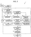
- FIG. 2 is a control block diagram of the arithmetic processing unit 41 according to the first embodiment.
- the arithmetic processing unit 41 functions as an attached-object detection unit 6, an attached-object region storage unit 7, an attached-object elimination monitoring unit 8, an attached-object region integration unit 9, a control signal outputting unit 10, an attached-object detection control unit 11, and an attached-object elimination management unit 12.
- the attached-object detection unit 6 detects an attached object on the lens of the camera 2 by using a photographed image output from the camera 2.
- the attached-object detection unit 6 includes a water drop detection unit 61 that detects a water drop, and a mud detection unit 62 that detects mud.
- Each of the water drop detection unit 61 and the mud detection unit 62 is operated on the basis of an operation command from the attached-object detection control unit 11. In other words, each of the water drop detection unit 61 and the mud detection unit 62 is switched between an operated state and a stopped state on the basis of an operation command from the attached-object detection
- the water drop detection unit 61 detects a water drop attached to the lens and outputs information indicating a region where the water drop is attached (water drop region, in the following) in a photographed image (water drop region information, in the following) to the attached-object region storage unit 7. A detailed operation of the water drop detection unit 61 will be described later.
- the mud detection unit 62 detects mud attached to the lens and outputs information indicating a region where the mud is attached (mud region, in the following) in a photographed image (mud region information, in the following) to the attached-object region storage unit 7.
- mud region information a region where the mud is attached
- mud region information a photographed image
- attached-object region storage unit 7 the water drop region and the mud region are collectively called an "attached-object region.”
- the water drop region information and the mud region information are collectively called “attached-object region information" in the following.
- the attached-object region storage unit 7 stores attached-object region information input from the attached-object detection unit 6.
- the attached-object region storage unit 7 includes a water drop region storage unit 71 corresponding to the water drop detection unit 61, and a mud region storage unit 72 corresponding to the mud detection unit 62.
- the water drop region storage unit 71 stores attached-object information input from the water drop detection unit 61, that is, water drop region information.
- the mud region storage unit 72 stores attached-object information input from the mud detection unit 62, that is, mud region information.
- FIG. 3 is a view illustrating an example of attached-object region information stored in the attached-object region storage unit 7.
- a region 14 where an attached object is detected is indicated on a detection surface 131 that is a photographed image divided in a grid manner.
- the region 14 where an attached object is detected is a region specified by attached-object region information.
- the attached-object elimination monitoring unit 8 monitors attached-object region information stored in each storage unit of the attached-object region storage unit 7 and detects a region where an attached object on the lens of the camera 2 is removed.
- the attached-object elimination monitoring unit 8 outputs information indicating a region where removal of an attached object is detected (attached-object elimination region information, in the following) to the attached-object elimination management unit 12.
- the attached-object elimination monitoring unit 8 includes monitoring units respectively corresponding to the storage units of the attached-object region storage unit 7, that is, a water drop elimination monitoring unit 81 and a mud elimination monitoring unit 82.
- the water drop elimination monitoring unit 81 monitors water drop region information stored in the water drop region storage unit 71 and detects a region where a water drop is eliminated (water drop elimination region, in the following) from a temporal change in the water drop region information. Then, the water drop elimination monitoring unit 81 outputs information indicating a water drop elimination region (water drop elimination region information, in the following).
- the mud elimination monitoring unit 82 monitors mud region information stored in the mud region storage unit 72 and detects a region where mud is eliminated (mud elimination region, in the following) from a temporal change in the mud region information. Then, the mud elimination monitoring unit 82 outputs information indicating a mud elimination region (mud elimination region information, in the following).
- the attached-object detection control unit 11 includes a state switching table 17 in which a condition for switching operations of the water drop detection unit 61 and the mud detection unit 62 is described.
- the attached-object detection control unit 11 performs the following two operations when determining that there is correspondence to the condition described in the state switching table 17.
- a first operation is outputting, to the attached-object detection unit 6, a command for switching an operation, that is, an operation command indicating switching to an operated state or an operation command indicating switching to a stopped state.
- a second operation is outputting information of an operation state of the attached-object detection unit 6 to the attached-object elimination management unit 12.
- the conditions described in the state switching table 17 include a vehicle speed of the vehicle 1.
- FIG. 4 is a view illustrating an example of the state switching table 17.
- the state switching table 17 includes a column of a processing name 171, a column of a state 172, and a column of a state switching condition 173. Processing to be controlled is described in the column of the processing name 171, and "water drop detection” indicates that the water drop detection unit 61 is to be controlled and “mud detection” indicates that the mud detection unit 62 is to be controlled. A state after switching is described in the column of the state 172, and “stopped” indicates that switching to a stopped state is performed and “operated” indicates that switching to an operated state is performed. A switching condition is described in the column of the state switching condition 173. For example, the second row in FIG.
- the attached-object detection control unit 11 may refer to a clock (not illustrated) included in the vehicle 1 or the in-vehicle device 4 or may use illuminance detected by the camera 2 or average luminance of a photographed image. Also, time to be a reference in determination whether it is day or night may vary depending on a season.
- the attached-object elimination management unit 12 rewrites the attached-object region information of an attached-object region storage unit 7 corresponding to a detection unit in a stopped state by using attached-object elimination region information.
- attached-object region information stored in the mud region storage unit 72 corresponding to the mud detection unit 62 in the stopped state is rewritten by utilization of attached-object elimination region information. That is, in this case, the mud region information is rewritten by utilization of water drop elimination region information. Rewriting of attached-object region information will be described in detail with reference to FIG. 3 , FIG. 5, and FIG. 6 .
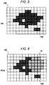
- FIG. 5 is a view illustrating mud regions 151 and 152 detected previously by the mud detection unit 62 in the stopped state.
- the mud regions 151 and 152 are displayed as regions on a detection surface 132 that is a photographed image divided in a grid manner.
- FIG. 6 is a view illustrating a mud region indicated by mud region information rewritten by the attached-object elimination management unit 12.
- FIG. 6 is generated through the following processing.
- the mud detection unit 62 detects a mud region from a photographed image and outputs mud region information to the attached-object region storage unit 7.
- This mud region information is illustrated as the region 151 and the region 152 in FIG. 5 .
- the mud detection unit 62 is switched to the stopped state by the attached-object detection control unit 11.
- the water drop elimination monitoring unit 81 detects the region 14, which is illustrated in FIG. 3 , as a water drop elimination region.
- the attached-object elimination management unit 12 excludes the region 14, which is the water drop elimination region, from the mud region 151 and region 152 illustrated in FIG. 5 .
- the mud region 151 illustrated in FIG. 5 is rewritten into a mud region 151A in FIG. 6 and is output to the attached-object region storage unit 7 as new mud region information along with the mud region 152 that is not rewritten.
- the attached-object region integration unit 9 acquires water drop region information and mud region information from the attached-object region storage unit 7.
- the attached-object region integration unit 9 integrates, as an integrated attached-object region, a water drop region and a mud region included in the acquired information and outputs integrated attached-object region information that is information indicating the integrated attached-object region to the control signal outputting unit 10.
- the control signal outputting unit 10 generates a control signal to drive the annunciation unit 5 on the basis of the input integrated attached-object region information and performs an output thereof to the annunciation unit 5. For example, the control signal outputting unit 10 generates a specific control signal in a case where an area of the integrated attached-object region indicated by the integrated attached-object region information is larger than a predetermined area.
- This specified control signal is a control signal for the annunciation unit 5 to give an alarm to a passenger of a vehicle to wipe an attached object on the lens of the camera 2.
- FIG. 7 is a flowchart illustrating processing by the water drop detection unit 61.
- An execution subject of each step described in the following is the CPU of the arithmetic processing unit 41.
- the CPU performs edge extraction processing with respect to a photographed image output from the camera 2 and generates an edge image.
- various means to extract a change amount in an image can be used.
- a Prewitt filter or a Sobel filter can be used.
- the CPU extracts a blurred pixel with low edge strength from the edge image generated in step S181.
- the CPU extracts an edge which is included in the edge image and edge strength of which is equal to or higher than a predetermined threshold Th1 and equal to or lower than a threshold Th2.
- step S183 the CPU accumulates an extraction result in step S182 for the predetermined number of times N for each pixel.
- the CPU specifies a pixel in which the edge strength accumulated in step S183 is equal to or higher than a predetermined threshold Th3, and outputs information indicating the pixel as water drop region information to the attached-object region storage unit 7.
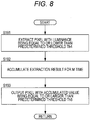
- FIG. 8 is a flowchart illustrating processing by the mud detection unit 62.
- An execution subject of each step described in the following is the CPU of the arithmetic processing unit 41.
- the CPU extracts a pixel, luminance of which is equal to or lower than a predetermined threshold Th4, in a photographed image output from the camera 2.
- the CPU accumulates an extraction result in step S191 for the predetermined number of times M for each pixel.
- the CPU outputs information, which indicates a pixel with the luminance value accumulated in step S192 being equal to or larger than a predetermined threshold Th5, as mud region information to the attached-object region storage unit 7.
- FIG. 9 is a flowchart illustrating processing by the attached-object elimination management unit 12. An execution subject of each step described in the following is the CPU of the arithmetic processing unit 41.
- step S161 the CPU determines whether the attached-object elimination management unit 12 receives water drop elimination region information from the water drop elimination monitoring unit 81.
- the processing advances to step S162 in a case where it is determined that the water drop elimination region information is received, and advances to step S164 in a case where it is determined that the water drop elimination region information is not received.
- step S162 the CPU determines whether the mud detection unit 62 is in a stopped state on the basis of an output from the attached-object detection control unit 11. This determination is performed on the basis of information of an operation state of the attached-object detection unit 6 which information is output from the attached-object detection control unit 11.
- step S163 in a case where it is determined that the mud detection unit 62 is in the stopped state, and advances to step S164 in a case where it is determined that the mud detection unit 62 is not in the stopped state, that is, the mud detection unit 62 is in an operated state.
- step S163 the CPU rewrites mud region information on the basis of the water drop elimination region information and goes to step S164.
- step S164 the CPU determines whether the attached-object elimination management unit 12 receives mud elimination region information from the mud elimination monitoring unit 82.
- the processing illustrated in FIG. 9 advances to step S165 in a case where it is determined that the mud elimination region information is received, and is ended in a case where it is determined that the water drop elimination region information is not received.
- step S165 the CPU determines whether the water drop detection unit 61 is in a stopped state on the basis of an output from the attached-object detection control unit 11. The processing illustrated in FIG.
- step S166 the CPU rewrites water drop region information on the basis of the mud elimination region information and ends the processing illustrated in FIG. 9 .
- the attached-object elimination management unit 12 can determine which of water drop region information and mud region information is to be rewritten.
- a vehicle monitoring unit 3 of a vehicle 1 and an attached-object detection control unit 11 of an in-vehicle device 4 may be omitted.
- an attached-object elimination management unit 12 rewrites attached-object region information of a water drop region storage unit 71 and a mud region storage unit 72 on the basis of attached-object elimination region information regardless of an operation state of a water drop detection unit 61 and a mud detection unit 62.
- An attached-object detection control unit 11 may control an operation of a water drop detection unit 61 and a mud detection unit 62 with reference to a state of a manual switch that can be operated by a passenger of a vehicle 1 instead of referring to a state switching table 17.
- An in-vehicle device 4 may not include any one of a water drop elimination monitoring unit 81 and a mud elimination monitoring unit 82. That is, an attached-object elimination monitoring unit 8 may generate attached-object elimination region information by using only a detection result of any one of a water drop detection unit 61 and a mud detection unit 62.
- the attached-object elimination monitoring unit 8 preferably includes the water drop elimination monitoring unit 81.
- a second embodiment of an in-vehicle device will be described with reference to FIG. 10 to FIG. 11 .
- the same sign is assigned to a configuration element that is the same with that of the first embodiment, and a different point will be mainly described.
- a point that is not specifically described is the same with the first embodiment.
- the present embodiment is different from the first embodiment mainly in a point that attached-object elimination region information is generated on the basis of a result of image recognition and in a point that it is changed according to a condition which attached-object elimination region information by which generation method is used to rewrite an attached-object region storage unit 7.
- a hardware configuration of each of a vehicle 1 and an in-vehicle device 4 in the second embodiment is similar to that of the first embodiment.
- a program stored in a ROM of an arithmetic processing unit 41 is different from that of the first embodiment.
- FIG. 10 is a control block diagram of the in-vehicle device 4 in the second embodiment of the present invention.
- An arithmetic processing unit 41 functions as an image recognition unit 20, an image recognition region storage unit 21, an attached-object detection unit 6, an attached-object region storage unit 7, an attached-object elimination monitoring unit 8, an attached-object region integration unit 9, a control signal outputting unit 10, and an attached-object elimination management unit 12.
- a different point between the control block diagram illustrated in FIG. 10 and the control block diagram in the first embodiment is that the image recognition unit 20 and the image recognition region storage unit 21 are added and that an output from the image recognition region storage unit 21 and that from a vehicle monitoring unit 3 are input into the attached-object elimination management unit 12.
- a line that connects the vehicle monitoring unit 3 and an attached-object detection control unit 11 is omitted in FIG. 10 .
- an output from the vehicle monitoring unit 3 is input into the attached-object detection control unit 11.
- a point that the attached-object detection control unit 11 includes a state switching table 17 is similar to the first embodiment. In the following, these different points will be described.
- the image recognition unit 20 includes a pedestrian detection unit 201 that detects a pedestrian from a photographed image, and a vehicle detection unit 202 that detects a vehicle from the photographed image.
- a region of the pedestrian, which is detected by the pedestrian detection unit 201, on the photographed image and a region of the vehicle, which is detected by the vehicle detection unit 202, on the photographed image are called an "image recognition region" in the following.
- the pedestrian detection unit 201 and the vehicle detection unit 202 respectively detect a pedestrian and a vehicle from the photographed image by using a known image processing method.
- image processing for example, a method of extracting a Hog feature amount from an image and extracting a region corresponding to a feature amount of a pedestrian or a vehicle, or a method of detecting a pedestrian or a vehicle by using deep learning can be used.
- Each of the pedestrian detection unit 201 and the vehicle detection unit 202 outputs, to the image recognition region storage unit 21, information of an image recognition region such as a position, shape, or size of a detected object on a photographed image as image recognition information.
- the image recognition region storage unit 21 includes a pedestrian region storage unit 211 and a vehicle region storage unit 212.
- the pedestrian region storage unit 211 stores the latest image recognition information input from the pedestrian detection unit 201.
- the vehicle region storage unit 212 stores the latest image recognition information input from the vehicle detection unit 202.
- the image recognition region storage unit 21 eliminates the image recognition information. It is because when previously-output image recognition information is held, erroneous determination is made that a pedestrian or a vehicle is currently recognized although none is currently recognized.
- image recognition information stored in the image recognition region storage unit 21 and an operation situation of a vehicle such as a vehicle speed from the vehicle monitoring unit 3 are input into the attached-object elimination management unit 12.
- the attached-object elimination management unit 12 includes an elimination relation table 22.
- the attached-object elimination management unit 12 rewrites water drop region information and mud region information stored in the attached-object region storage unit 7 on the basis of the elimination relation table 22.
- the elimination relation table 22 is a table for specification of information to be rewritten according to a processing result of each of the attached-object detection unit 6 and the image recognition unit 20 on the basis of a period of time, and an operation situation of a vehicle which situation is input from the vehicle monitoring unit 3. Note that it can be said that the elimination relation table 22 indicates a condition for the attached-object elimination management unit 12 to be operated.
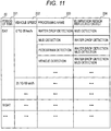
- FIG. 11 is a view illustrating an example of the elimination relation table 22.
- the elimination relation table 22 includes a column of a period of time 221, a column of a vehicle speed 222, a column of a processing name 223, and a column of an elimination region reflected object 224.
- the column of the period of time 221 information indicating a division of time such as day or night is described.
- the column of the vehicle speed 222 a condition for a vehicle speed of the vehicle 1 is described.
- a name of any detection unit of the attached-object detection unit 6 and the image recognition unit 20 is described.
- a storage region to be rewritten that is, any of a water drop region storage unit 71 and a mud region storage unit 72 is described.
- the following is indicated according to the second row of the elimination relation table 22 in FIG. 11 . That is, in a case where traveling is performed at a vehicle speed of 20 km/h during the day, it is assumed that mud in a region, which corresponds to a water drop elimination region detected by a water drop elimination monitoring unit 81, in a mud region stored in the mud region storage unit 72 is removed and mud region information indicating that mud is attached to the region is eliminated from the mud region storage unit 72.
- the period of time 221 and the vehicle speed 222 are used as conditions of changing an elimination region reflected object. However, these are not the limitation. Also, an operation state or the like of each detection unit of the attached-object detection unit 6 can be used.
- the elimination relation table 22 By appropriately setting the elimination relation table 22, with an elimination region of an attached object detected by a different attached-object detection unit that corresponds to the state switching condition in FIG. 4 and that is currently operated, it is possible to eliminate an attached-object region that is stored by an attached-object detection unit, which corresponds to the state switching condition in FIG. 4 and which is currently stopped, during operation before stoppage. Also, a wiping relationship according to a kind of an attached object can be reflected to the elimination relation table 22. For example, since a water drop makes many attached objects including mud come off and washes these away, a water drop elimination region acquired by water drop detection processing can be easily used for elimination of a dirt region acquired by different dirt detection processing. However, mud has a property of being easily mixed with a different attached object and it is difficult to use a mud elimination region acquired by mud detection processing for elimination of a dirt region acquired by different dirt detection processing.
- the in-vehicle device 4 can rewrite attached-object region information by using a recognition result of the image recognition unit 20 or a detection result of the attached-object detection unit 6 on the basis of the speed of the vehicle 1 and the elimination relation table 22.
- An in-vehicle device 4 may not include an image recognition unit 20 and an image recognition region storage unit 21.
- an attached-object elimination management unit 12 rewrites attached-object region information stored in an attached-object region storage unit 7 on the basis of an elimination relation table 22 instead of an operation state of an attached-object detection unit 6.
- an attached-object elimination monitoring unit 8 in the in-vehicle device 4.
- the attached-object elimination management unit 12 eliminates a region of image recognition information, which is input from an image recognition region storage unit 21, from attached-object region information described in the attached-object region storage unit 7.
- An attached-object elimination management unit 12 may not refer to a column of a vehicle speed 222 in an elimination relation table 22. Moreover, the attached-object elimination management unit 12 may not refer to a column of a period of time in the elimination relation table 22. In these cases, the elimination relation table 22 may not include a column that is not referred to by the attached-object elimination management unit 12.
- an attached-object elimination management unit 12 may consider accuracy when eliminating attached-object information stored in an attached-object region storage unit 7.
- a water drop detection unit 61 of the attached-object detection unit 6 sets a pixel with an accumulated value being equal to or larger than Th3 as a water drop region. Accuracy can be determined by utilization of the accumulated value.
- the water drop detection unit 61 sets that accuracy is high, that is, a detection result is more likely to be certain as an accumulated value becomes large.
- a mud detection unit 62 of the attached-object detection unit 6 sets a pixel with an accumulated value being equal to or larger than Th5 as a mud region. Accuracy can be determined by utilization of the accumulated value.
- the mud detection unit 62 sets that accuracy is high, that is, a detection result is more likely to be certain as an accumulated value becomes large.
- a water drop elimination monitoring unit 81 of the attached-object elimination monitoring unit 8 sets accuracy, which is set in the pixel before the elimination, as accuracy of elimination of a water drop in the pixel.
- a mud elimination monitoring unit 82 sets accuracy, which is set in the pixel before the elimination, as accuracy of elimination of mud in the pixel.
- Each detection unit of the image recognition unit 20 assigns, to a detected image recognition region, certainty of the detection as accuracy information, makes each storage unit of an image recognition region storage unit 21 store this, and inputs this into the attached-object elimination management unit 12.
- the attached-object elimination management unit 12 assigns positive weight corresponding to accuracy to each image recognition region and assigns negative weight corresponding to accuracy to each attached-object elimination region. Then, the attached-object elimination management unit 12 extracts a region in which the sum of the weight is equal to or smaller than a predetermined value and eliminates the extracted region from the attached-object region storage unit 7 on the basis of the elimination relation table 22 in the above-described manner.
- An image recognition unit 20 only needs to be able to detect some kind of object from a photographed image from a camera 2 and a kind or the number of detection objects are not limited to the above configuration.
- an image recognition unit 20 may include only a pedestrian detection unit 201 or may include a detection unit that detects a traffic light or a guard rail in addition to a pedestrian or a vehicle.
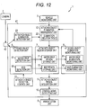
- a third embodiment of an in-vehicle device according to the present invention will be described with reference to FIG. 12 to FIG. 13 .
- the same sign is assigned to a configuration element that is the same with that of the second embodiment, and a different point will be mainly described.
- a point that is not specifically described is the same with the second embodiment.
- the present embodiment is different from the second embodiment mainly in a point that an attached-object detection unit that detects an elimination point of an attached object without limitation to a specific kind of dirt is included.
- a hardware configuration of each of a vehicle 1 and an in-vehicle device 4 in the third embodiment is similar to that of the second embodiment.
- a program stored in a ROM of an arithmetic processing unit 41 is different from that of the second embodiment.
- FIG. 12 is a control block diagram of the in-vehicle device 4 in the third embodiment of the present invention.
- An arithmetic processing unit 41 includes an attached-object elimination detection unit 23, an attached-object detection unit 6, an attached-object region storage unit 7, an attached-object elimination monitoring unit 8, an attached-object region integration unit 9, a control signal outputting unit 10, and an attached-object elimination management unit 12.
- a point different from the control block diagram in the second embodiment is that an image recognition unit 20 and an image recognition region storage unit 21 are omitted, an attached-object elimination detection unit 23 is added, and an output from the attached-object elimination detection unit 23 is input into the attached-object elimination management unit 12.
- a line that connects a vehicle monitoring unit 3 and an attached-object detection control unit 11 is omitted in FIG. 12 .
- an output from the vehicle monitoring unit 3 is input into the attached-object detection control unit 11.
- a point that the attached-object detection control unit 11 includes a state switching table 17 is similar to the second embodiment. In the following, these different points will be described.
- the attached-object elimination detection unit 23 detects a region, in which an attached object is removed, from a photographed image input from a camera 2.
- the attached-object elimination detection unit 23 detects, for example, a region where an attached object is removed (attached-object elimination detection region, in the following) by using a temporal change in the photographed image input from the camera 2, and outputs attached-object elimination detection region information indicating the region to the attached-object elimination management unit 12.
- the attached-object elimination management unit 12 rewrites a water drop region and a mud region of the attached-object region storage unit 7 on the basis of attached-object elimination region information input from the attached-object elimination monitoring unit 8 and attached-object elimination detection region information input from the attached-object elimination detection unit 23. That is, in the present embodiment, the attached-object elimination region information and the attached-object elimination detection region information are dirt removal information.
- an elimination region reflected object 224 of the attached-object elimination detection unit 23 is set to both of water drop detection and mud detection. That is, both of water drop region information and mud region information are rewritten on the basis of the attached-object elimination detection region information output from the attached-object elimination detection unit 23.
- FIG. 13 is a flowchart illustrating an operation of the attached-object elimination detection unit 23.
- An execution subject of each step described in the following is a CPU of the arithmetic processing unit 41.
- the CPU accumulates a photographed image output from the camera 2 for a long time, estimates that an attached object is attached to a region with no change, and extracts this as a no-change region.
- processing in the present step is processing to detect an attached object on a lens of the camera 2 and a processing result of the attached-object detection unit 6 can be also used.
- the CPU evaluates a difference such as a luminance difference in each pixel of two successive photographed images output from the camera 2.
- the CPU extracts, as an instantaneous change region, an aggregation of pixels with the difference being larger than a predetermined threshold.
- the extraction of an instantaneous change region in the present step intends the following. That is, when a photographing cycle of the camera 2 is adequately short, there is little change in two successive photographed images and a difference region is not usually extracted by the processing in step 242. However, at a moment at which an attached object is attached to the lens of the camera 2 or a moment at which the attached object is removed, a great change is generated in a position where the attached object is attached and the region is extracted as an instantaneous change region.
- the CPU outputs, as an attached-object elimination detection region, a region that is included in the instantaneous change region extracted in step 242 and that is extracted as the no-change region in step 241.
- the following effect can be acquired in addition to the effects of (1) to (5) in the first embodiment and the effects of (1), (2), and (4) in the second embodiment.
- the attached-object elimination detection unit 23 detects a region where an attached object is removed. In other words, a region where no attached object is detected in the latest photographed image and where an attached object is detected in a previous photographed image is detected. However, a region where no attached object is detected (non attached-object region, in the following) may be detected without consideration of previous existence/non-existence of an attached object. Detection of a non attached-object region by an attached-object elimination detection unit 23 can be performed, for example, by utilization of a change in a photographed image, which is output from a camera 2, along with traveling of a vehicle.
- FIG. 14 is a flowchart illustrating an operation of an attached-object elimination detection unit 23 in the present modification example.
- An execution subject of each step in the flowchart described in the following is a CPU of an arithmetic processing unit 41.
- the CPU accumulates a photographed image output from the camera 2 for a certain period of time.
- the CPU divides a plurality of successive photographed images accumulated in step 251 into a plurality of regions and outputs a distribution value of luminance, that is, a degree of a temporal luminance variation in each of the regions.
- the plurality of regions is, for example, a total of one hundred regions that are a photographed image equally divided into ten in each of a vertical direction and a horizontal direction.
- the CPU refers to the output in step 252 and outputs, as a non attached-object region, a region where a distribution value of luminance is equal to or larger than a predetermined threshold Th6. It is because in a region with no attached object, luminance of the region in a photographed image changes along with traveling of a vehicle 1.
- An in-vehicle device 4 may include, as an attached-object elimination detection unit 23, the image recognition unit 20 and the image recognition region storage unit 21 in the second embodiment.
- an attached-object elimination detection unit 23 a region of an object that is detected by the image recognition unit 20 from a photographed image, that is, an image recognition region is output as a non attached-object region to an attached-object elimination management unit 12.
- a reason why the image recognition region is output as the non attached-object region is as follows. That is, since the image recognition region is a region where an object is detected by the image recognition unit 20, it can be estimated that there is no attached object in the image recognition region.
- a fourth embodiment of an in-vehicle device according to the present invention will be described with reference to FIG. 15 to FIG. 16 .
- the same sign is assigned to a configuration element that is the same with that of the second embodiment, and a different point will be mainly described.
- a point that is not specifically described is the same with the second embodiment.
- the present embodiment is different from the second embodiment mainly in a point that a region where a lens is cleaned is treated as a region where an attached object is eliminated.
- a hardware configuration of an in-vehicle device 4 in the fourth embodiment is similar to that of the second embodiment.
- a program stored in a ROM of an arithmetic processing unit 41 is different from that of the second embodiment.
- a hardware configuration of the vehicle 1 includes, in addition to the configuration in the second embodiment, a device (not illustrated) that executes a program using a photographed image from,a camera 2 (image utilization program, in the following) such as a program of detecting a white line from a photographed image and controlling the vehicle 1.
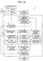
- FIG. 15 is a control block diagram of an in-vehicle device 4 according to the fourth embodiment of the present invention.
- an arithmetic processing unit 41 functions as a lens cleaning control unit 26, an attached-object detection unit 6, an attached-object region storage unit 7, an attached-object elimination monitoring unit 8, an attached-object region integration unit 9, a control signal outputting unit 10, and an attached-object elimination management unit 12.
- the vehicle 1 includes a lens cleaning unit 27 that cleans a lens of the camera 2.
- the lens cleaning unit 27 includes a wiper 271 that rubs off (wipe) an attached object on a lens, and a washer 272 that sprays a cleaning solution to the lens and washes off the attached object on the lens.
- the lens cleaning unit 27 is operated on the basis of a cleaning operation command from the lens cleaning control unit 26 (described later).
- Different points between the control block diagram illustrated in FIG. 15 and the control block diagram in the second embodiment are the following five points. That is, these are a point that the vehicle 1 includes the lens cleaning unit 27, a point that an image recognition unit 20 and an image recognition region storage unit 21 are omitted, a point that the in-vehicle device 4 includes the lens cleaning control unit 26, a point that an output from the lens cleaning control unit 26 is input into the attached-object elimination management unit 12, and a point that an output from the control signal outputting unit 10 is input into the lens cleaning control unit 26. Note that a line that connects a vehicle monitoring unit 3 and an attached-object detection control unit 11 is omitted in FIG. 15 .
- an output from the vehicle monitoring unit 3 is input into the attached-object detection control unit 11.
- a point that the attached-object detection control unit 11 includes a state switching table 17 is similar to the second embodiment. In the following, these different points will be described.
- the control signal outputting unit 10 determines whether a photographed image from the camera 2 fits to the above-described image utilization program. When determining that the photographed image does not fit to the image utilization program, the control signal outputting unit 10 outputs a control operation command to the lens cleaning control unit 26.
- the determination by the control signal outputting unit 10 whether a photographed image fits to the image utilization program is performed, for example, on the basis of a rate of an area of an integrated attached-object region in the photographed image or a position of the integrated attached-object region in the photographed image.
- the control operation command output from the control signal outputting unit 10 to the lens cleaning control unit 26 may be a control operation command that constantly makes both of the wiper 271 and the washer 272 operated, or a control operation command that makes only one of the wiper 271 and the washer 272 operated on the basis of the integrated attached-object region.
- control signal outputting unit 10 may switch an activated function of the lens cleaning unit 27 according to a kind of an attached object on the lens of the camera 2. For example, in a case of determining that a water drop is attached, the control signal outputting unit 10 outputs a control operation command of operating the wiper 271. Also, in a case of determining that mud is attached, the control signal outputting unit 10 outputs a control operation command of activating, in addition to the wiper 271, the washer 272 to make mud come off.
- the lens cleaning control unit 26 When receiving a control operation command from the control signal outputting unit 10, the lens cleaning control unit 26 outputs a cleaning operation command to the lens cleaning unit 27 and outputs cleaned region information to the attached-object elimination management unit 12.
- the cleaned region information is information indicating a region on a photographed image in which region an attached object is removed when the lens cleaning unit 27 cleans the lens of the camera 2 (cleaned region, in the following). For example, a region where the wiper 271 rubs off an attached object becomes a cleaned region in a case where the wiper 271 is operated, and a whole region of a photographed image becomes a cleaned region in a case where the washer 272 is operated.
- FIG. 16 is a view illustrating an example of a cleaned region of a case where the wiper 271 is operated.
- a cleaned region 28 is a region where the wiper 271 is operated on a detection surface 133 that is a photographed image divided in a grid manner. Referring back to FIG. 15 , a description of the lens cleaning control unit 26 is continued.
- Cleaned region information is previously stored in the lens cleaning control unit 26.
- a cleaning operation command and cleaned region information that are output from the lens cleaning control unit 26 correspond to a received control operation command. For example, when a control operation command of operating only the wiper 271 is received, a cleaning operation command of operating only the wiper 271 and cleaned region information of a case where only the wiper 271 is activated are output.
- the attached-object elimination management unit 12 rewrites a water drop region and a mud region of the attached-object region storage unit 7 on the basis of attached-object elimination region information input from the attached-object elimination monitoring unit 8 and cleaned region information input from the lens cleaning control unit 26. That is, in the present embodiment, the attached-object elimination region information and the cleaned region information are dirt removal information.
- an elimination region reflected object 224 is described for each function of the lens cleaning unit 27 controlled by the lens cleaning control unit 26.
- the wiper 271 it is possible to wipe off a water drop but it is difficult to remove mud when the lens is not wet.
- the elimination region reflected object 224 of the wiper 271 in the elimination relation table 22 is only water drop detection in principle.
- the washer 272 can wash off a water drop and mud, the elimination region reflected object 224 of the washer 272 is water drop detection and mud detection.
- the lens cleaning control unit 26 preferably switches an activated function of the lens cleaning unit 27 according to a kind of an attached object on the lens of the camera 2.
- the wiper 271 is activated in a case where a water drop is attached and the washer 272 and the wiper 271 are activated in a case where mud is attached.
- the control signal outputting unit 10 inputs a degree and a kind of an attached object on the lens of the camera 2 into the lens cleaning control unit 26.
- the following effect can be acquired in addition to the effects of (1) to (5) in the first embodiment and the effects of (1), (2), and (4) in the second embodiment.
- the in-vehicle device 4 can output an operation command to the lens cleaning unit 27 and generate dirt removal information in which a region cleaned by the wiper 271 and/or washer 272 operated by the operation command is a region where dirt is removed.
- the lens cleaning control unit 26 Since a lens cleaning control unit 26 cannot check whether an attached object is actually removed, there is a possibility that there is an attached object remaining in an attached-object cleaned region even when a lens cleaning unit 27 is operated. Thus, the lens cleaning control unit 26 may not input an attached-object cleaned region into an attached-object elimination management unit 12. Instead, the lens cleaning control unit 26 shortens an execution interval of an attached-object elimination monitoring unit 8, that is, increases a speed of processing before and after activation of the lens cleaning unit 27, whereby removal of an attached object by an operation of the lens cleaning unit 27 is securely detected.
- the lens cleaning control unit 26 may reduce a load on an arithmetic processing unit 41 due to processing by the attached-object elimination monitoring unit 8.
- the attached-object elimination monitoring unit 8 is operated only when the lens cleaning unit 27 is operated, removal of an attached object which removal is not due to an operation by the lens cleaning unit 27 is not detected.
- application is preferably performed in a situation in which an attached object on the lens of the camera 2 is not naturally removed.
- a lens cleaning control unit 26 may include a table where which of monitoring units of an attached-object elimination monitoring unit 8 is operated or a speed of an operation of which is increased is determined according to an operated function of a lens cleaning unit 27.
- a water drop elimination monitoring unit 81 corresponds to an operation of a wiper 271 and the water drop elimination monitoring unit 81 and a mud elimination monitoring unit 82 correspond to an operation of a washer 272.
- the water drop elimination monitoring unit 81 is operated or a speed of an operation of the water drop elimination monitoring unit 81 is increased.
- a vehicle 1 further includes a manual switch (not illustrated) and a control operation command may be output to a lens cleaning control unit 26 on the basis of operation on the manual switch by a passenger.
- An attached-object detection unit 6 includes a water drop detection unit 61 and a mud detection unit 62, and may further include a detection unit that detects a different kind of dirt such as a white turbidity detection unit. Also, it is only necessary to include at least two dirt detection units such as a water drop detection unit 61 and a white turbidity detection unit in the first embodiment, and it is only necessary to include at least one dirt detection unit in each of the second to fourth embodiments.
- a white turbidity detection unit detects white turbidity, which is one kind of dirt, in the following manner.
- the white turbidity detection unit sets an upper left detection region 941, an upper detection region 942, and an upper right detection region 943 in a position where a horizon is to appear on a photographed image.
- the upper detection region 942 is set in a position including a vanishing point of two lane markers provided in parallel on a road surface.
- a vanishing point 947 of two lane markers 946 is included on an inner side of the upper detection region 942.
- the upper left detection region 941 is set on a left side of the upper detection region 942 and the upper right detection region 943 is set on a right side of the upper detection region 942.
- the white turbidity detection unit sets a lower left detection region 944 and a lower right detection region 945 in a position where a lane marker is to appear on a photographed image.
- the white turbidity detection unit performs edge detection processing in a horizontal direction with respect to a pixel in each of the upper left detection region 941, the upper detection region 942, the upper right detection region 943, the lower left detection region 944, and the lower right detection region 945.
- edge detection with respect to the upper left detection region 941, the upper detection region 942, and the upper right detection region 943 an edge such as a horizon is detected.
- edge detection with respect to the lower left detection region 944 and the lower right detection region 945 an edge such as the lane markers 946 is detected.
- the white turbidity detection unit calculates edge strength in each pixel included in each of the detection regions 941 to 945.
- the white turbidity detection unit calculates an average value AE2 of edge strength in each of the detection regions 941 to 945 and determines whether the average value AE2 is smaller than a predetermined threshold ⁇ .
- the white turbidity detection unit determines that there is white turbidity in a detection region in which the average value AE2 of the edge strength is smaller than the threshold ⁇ .
- the white turbidity detection unit can calculate certainty, that is, accuracy of white turbidity in the following manner.
- the white turbidity detection unit calculates the number of detection regions in which the average value AE2 of the edge strength is smaller than the threshold ⁇ , that is, the number N2 of detection regions determined to have white turbidity among the detection regions 941 to 945. Subsequently, the white turbidity detection unit calculates time t2 in which it is continuously determined that each of the detection regions 941 to 945 has white turbidity. Then, the white turbidity detection unit calculates average duration t3 by dividing the sum of the time t2 of the detection regions 941 to 945 by the number of detection regions, that is, five. The white turbidity detection unit converts this average duration t3 into accuracy R2 of a detection result of the white turbidity detection unit.
- the accuracy R2 indicates that accuracy is high and there is white turbidity as the average duration t3 of the white turbidity becomes longer. Also, since t3 itself is average white turbidity duration of the five detection regions 941 to 945, accuracy of white turbidity is increased as duration of all of the five detection regions 941 to 945 becomes long.
- the accuracy R2 is expressed by a numeric value from 0 to 1, and is expressed as 1 and becomes a value indicating a state in which accuracy is high and there is white turbidity in a case where TTHR3 ⁇ t3.
- a water drop detection unit 61 may detect a water drop in the following manner.
- the water drop detection unit 61 divides an image region of a photographed image 930 into a plurality of blocks B (x, y) .
- Each block B (x, y) includes a plurality of pixels of the photographed image.
- the water drop detection unit 61 calculates a score S1 (x, y) indicating attachment time of a water drop with respect to each block B (x, y).
- An initial value of the score S1 (x, y) is zero and a predetermined value is added thereto each time it is determined that a water drop is attached to the block B (x, y) by determination described in the following.
- FIG. 18(b) is a view in which an arbitrary pixel 931 is a focus point.
- the water drop detection unit 61 sets, as an inner reference point 932, a pixel that is away from the focus point 931 for a predetermined distance such as three pixels in each of an upper direction, an upper right direction, a lower right direction, an upper left direction, and a lower left direction and sets, as an outer reference point 933, a pixel that is further away for a predetermined distance such as three pixels in each of the five directions.
- the water drop detection unit 61 calculates luminance for each of the inner reference point 932 and the outer reference point 933.
- the water drop detection unit 61 determines, with respect to each of the five directions, whether luminance of the inner reference point 932 is higher than luminance of the outer reference point 933. In other words, the water drop detection unit 61 determines whether the focus point 931 is a center part of a water drop. In a case where luminance of the inner reference point 932 in each direction is higher than luminance of the outer reference point 933 in the same direction, the water drop detection unit 61 increases a score S1 (x, y) of B (x, y), to which the focus point 931 belongs, for a predetermined value such as 1.
- the water drop detection unit 61 determines that a block, in which the score S1 (x, y) is equal to or larger than a predetermined value, as a region where a water drop is detected.
- the water drop detection unit 61 can further calculate accuracy of water drop detection in the following manner.
- the water drop detection unit 61 calculates elapsed time t1 after initialization of the score S1 (x, y) of each block B (x, y). Then, the water drop detection unit 61 divides the score S1 (x, y) of each block B (x, y) by the elapsed time t1 and calculates a time average S1 (x, y)/t1 of the score S1 (x, y). The water drop detection unit 61 calculates a score average AS1 by calculating the sum of the time average S1 (x, y)/t1 of all blocks B (x, y) and dividing this by the number of all blocks in the photographed image 930.
- the score average AS1 is increased in each frame.
- the water drop detection unit 61 generates accuracy R1 of a detection result of the water drop detection unit 61 by using this score average AS1.
- the score average AS1 is used as a current attachment amount of a water drop on the lens.
- a lens state changes greatly and there is a case where the score S1 (x, y) is temporarily decreased even when it is rainy in a case of a water drop.
- the water drop detection unit 61 holds the count CS1 of time even when the score average AS1 becomes lower than the constant value TAS1 for a certain predetermined period and decreases the score S1 (x, y) in a case where the score average AS1 becomes lower for the predetermined period or longer.
- the water drop detection unit 61 expresses the accuracy R1 by 1 in a case where the count CS1 of time exceeds AS1THR. As the accuracy R1 becomes closer to 1, attachment of a detected water drop becomes more reliable.
- a mud detection unit 62 may detect mud in the following manner.
- the mud detection unit 62 divides an image region of a photographed image 930 into a plurality of blocks B (x, y).
- the mud detection unit 62 calculates, for each block B (x, y), a value of a score S4 (x, y) in the following manner, an initial value thereof being zero.
- the mud detection unit 62 detects luminance of each pixel of the photographed image 930. Then, the mud detection unit 62 calculates, for each block B (x, y), the sum It (x, y) of the luminance of the pixels included in the block B (x, y). The mud detection unit 62 calculates, for each block B (x, y), a difference ⁇ I (x, y) between It (x, y) calculated for a photographed image in a current frame and I t-1 (x, y) calculated similarly for a photographed image in a previous frame.
- the mud detection unit 62 detects a block B (x, y) in which ⁇ I (x, y) is small and It (x, y) is small compared to a surrounding block and increases a score S4 (x, y) corresponding to the block B (x, y) for a predetermined value such as 1.
- the mud detection unit 62 determines that a block in which the score S4 (x, y) is equal to or larger than a predetermined value is a region where mud is detected.
- the mud detection unit 62 can further calculate accuracy of mud detection in the following manner.
- the mud detection unit 62 After performing the above-described determination with respect to all pixels in a photographed image, the mud detection unit 62 acquires a score integration value of the score S4 (x, y) in each block B (x, y) in a certain predetermined period t5. Then, the mud detection unit 62 calculates a time average S4 (x, y)/t5 of the score S4 (x, y) by dividing the score S4 (x, y) in each block B (x, y) by the predetermined period t5.
- the mud detection unit 62 calculates a score average AR S4 by calculating the sum of the time average S4 (x, y)/t5 of all blocks B (x, y) and dividing this by the number of all blocks in the photographed image 930. Meaning of the score average AR S4 is close to an amount of mud attached to the lens in a certain predetermined period.
- the score average AR S4 is increased in each frame imaged serially. In other words, in a case where the score average AR S4 is large, a probability that a lot of mud is attached to the lens is high. Also, time in which the score A S4 becomes larger than a threshold TA S4 is used as accuracy.
- the mud detection unit 62 expresses the accuracy R4 by 1 in a case where TA S4 exceeds AS4THR. As the accuracy R4 becomes closer to 1, attachment of detected mud becomes more reliable.
- a vehicle 1 may further include a vehicle control unit that controls traveling of a vehicle.
- a vehicle operation unit has a function of controlling an accelerator, a brake, or an angle of a steering wheel of a vehicle, and the like.
- a control signal outputting unit 10 generates a control signal on the basis of an integrated attached-object region input from an attached-object region integration unit 9 and inputs this into the vehicle operation unit.
- the integrated attached-object region is larger than an area corresponding to a predetermined rate in a photographed image, it is determined that performance in recognition of a surrounding environment by utilization of a photographed image from a camera 2 is low, and an accelerator or a brake is controlled in such a manner that a vehicle speed becomes equal to a lower than a certain speed or a vehicle is stopped.
- An in-vehicle device 4 may include an object recognition unit that performs image processing of detecting an object such as a lane marker or a pedestrian by using a photographed image from a camera 2, and a control signal outputting unit 10 may perform additional processing described in the following.
- the control signal outputting unit 10 generates, as a mask image, an integrated attached-object region input from an attached-object region integration unit 9 and inputs this into the object recognition unit.
- the object recognition unit excludes the integrated attached-object region indicated by the input mask image from a photographed image from the camera 2 and performs image processing to detect an object such as a lane marker or a pedestrian.
- the control signal outputting unit 10 outputs a fail signal to the object recognition unit. For example, in a case where a size of the integrated attached-object region exceeds a threshold, the control signal outputting unit 10 outputs a fail signal.
- the object recognition unit suspends the image processing while the fail signal is received. Also, the control signal outputting unit 10 may tell an annunciation unit 5 that the image processing by the object recognition unit is suspended.
- an attached-object elimination management unit 12 may rewrite the attached-object region information in such a manner that a whole attached-object region is deleted in a case where the following condition is satisfied. That is a case where a region indicated by the dirt removal information has an area equal to or larger than a predetermined rate of the attached-object region such as a case where a region indicated by the dirt removal information is equal to or larger than 80% of the attached-object region.
- An attached object on a lens of a camera 2 is an object in any of the above-described embodiments.
- an attached object on a window in front of the camera 2 may be an object.
- a lens cleaning unit 27 is a device that removes an attached object on the front window.
- an attached-object detection control unit 11 may not be included. In that case, a water drop detection unit 61 and a mud detection unit 62 are operated constantly. According to the present eighth modification example, there is an advantage that an attached-object elimination management unit 12 can rewrite water drop region information or mud region information and promptly update an integrated attached-object region even when the water drop detection unit 61 and the mud detection unit 62 are operated.
- An in-vehicle device 4 may output, as attached-object elimination region information, information of a region where no attached object is detected by a water drop detection unit 61 or a mud detection unit 62 to an attached-object elimination management unit 12 More specifically, a region where no attached object is detected by the water drop detection unit 61 and a region where no attached object is detected by the mud detection unit 62, that is, regions that are not stored into storage units of an attached-object region storage unit 7 are input as attached-object elimination regions into the attached-object elimination management unit 12.
- a vehicle speed monitoring unit 32 of a vehicle monitoring unit 3 may output that a vehicle speed is almost zero.
- the vehicle 1 enters a parking lot it is output to an attached-object detection control unit 11 that a vehicle speed is almost zero, and an operation of a mud detection unit 62 is stopped according to a description in a state switching table 17.
- a program is assumed to be stored in a ROM (not illustrated).
- an in-vehicle device 4 may include an input/output interface (not illustrated) and a program may be read from a different device through the input/output interface and a medium that can be used by the in-vehicle device 4.
- the medium indicates a storage medium that can be attached to/detached from the input/output interface, a communication medium, that is, a wired, wireless, or optical network, or a carrier wave or a digital signal propagated in the network.
- a part or all of a function realized by a program may be realized by a hardware circuit or FPGA.
Abstract
Description
- The present invention relates to an in-vehicle device.
- A technology of mounting a camera in a vehicle, performing image recognition processing or the like on an image acquired from the camera, and using this for a support for driving a vehicle has been known. When a foreign object such as a water drop or mud is attached to a lens of a camera, there is a bad influence on the image recognition processing. A device to detect an object attached to a lens is disclosed, for example, in
PTL 1. - PTL 1:
JP2012-38048 A - In the invention disclosed in
PTL 1, it is not possible to detect removal of dirt in a case where dirt detection cannot be performed. - An in-vehicle device according to a first aspect of the present invention includes an image acquisition unit that acquires an image photographed by a camera including a lens, a storage unit, a dirt detection unit that detects dirt on the lens on the basis of the image acquired by the image acquisition unit and that stores dirt region information indicating a region where the dirt exists in the image into the storage unit, a dirt removal information generation unit that generates dirt removal information indicating a region where the dirt on the lens is removed, and a rewriting unit that rewrites the dirt region information on the basis of the dirt removal information.
- According to the present invention, by rewriting dirt region information on the basis of dirt removal information indicating a region where dirt is removed, it is possible to accurately recognize a region of dirt even in a case where dirt detection cannot be performed.
-
- [
FIG. 1] FIG. 1 is a hardware configuration view of a vehicle in a first embodiment. - [
FIG. 2] FIG. 2 is a control block diagram of an in-vehicle device in the first embodiment. - [
FIG. 3] FIG. 3 is a view illustrating an example of attached-object region information. - [
FIG. 4] FIG. 4 is a view illustrating an example of a state switching condition table. - [
FIG. 5] FIG. 5 is a view illustrating a mud region. - [
FIG. 6] FIG. 6 is a view illustrating a mud region rewritten by an attached-object elimination storage unit. - [
FIG. 7] FIG. 7 is a flowchart illustrating processing by a water drop detection unit. - [
FIG. 8] FIG. 8 is a flowchart illustrating processing by a mud detection unit. - [
FIG. 9] FIG. 9 is a flowchart illustrating processing by an attached-object elimination management unit. - [
FIG. 10] FIG. 10 is a control block diagram of an in-vehicle device in a second embodiment. - [
FIG. 11] FIG. 11 is a view illustrating an example of an elimination relation table. - [
FIG. 12] FIG. 12 is a control block diagram of an in-vehicle device in a third embodiment. - [
FIG. 13] FIG. 13 is a flowchart illustrating an operation of an attached-object elimination detection unit. - [
FIG. 14] FIG. 14 is a flowchart illustrating an operation of an attached-object elimination detection unit in a first modification example of the third embodiment. - [
FIG. 15] FIG. 15 is a control block diagram of an in-vehicle device in a fourth embodiment. - [
FIG. 16] FIG. 16 is a view illustrating an example of a cleaned region of a case where a wiper is operated. - [
FIG. 17] FIG. 17 is a view for describing white turbidity detection. - [
FIG. 18] FIG. 18 is a view for describing water drop detection. - In the following, a first embodiment of an in-vehicle device according to the present invention will be described with reference to
FIG. 1 to FIG. 8 . -
FIG. 1 is a hardware configuration view of avehicle 1. Thevehicle 1 includes acamera 2, avehicle monitoring unit 3, an in-vehicle device 4, and anannunciation unit 5. - The
camera 2 is provided outwardly in thevehicle 1 and a photographing region thereof includes a road surface around thevehicle 1. Thecamera 2 performs photographing at predetermined time intervals and outputs an image acquired by the photographing (photographed image, in the following) to the in-vehicle device 4. Thecamera 2 includes a lens. When the lens becomes dirty due to mud or a water drop, a region corresponding to the dirt in a photographed image is influenced. - The
vehicle monitoring unit 3 acquires information related to a traveling state of thevehicle 1. Thevehicle monitoring unit 3 includes a rudder angle monitoring unit 31 and a vehiclespeed monitoring unit 32. The rudder angle monitoring unit 31 is, for example, an angle sensor and acquires rudder angle information of thevehicle 1. The vehiclespeed monitoring unit 32 is, for example, a rotary encoder and acquires a traveling speed, that is, a vehicle speed of thevehicle 1. Thevehicle monitoring unit 3 outputs vehicle information such as an acquired rudder angle or vehicle speed to the in-vehicle device 4. - The in-
vehicle device 4 includes anarithmetic processing unit 41 and animage acquisition unit 42. Thearithmetic processing unit 41 includes a CPU, a RAM, and a ROM. The CPU performs processing (described later) by deploying and executing, in the RAM, a program stored in the ROM. Theimage acquisition unit 42 acquires a photographed image from thecamera 2 and performs an output thereof to thearithmetic processing unit 41. Thearithmetic processing unit 41 stores the input photographed image in the RAM and performs predetermined image processing on the stored photographed image. For example, processing such as pedestrian detection of detecting a shape of a person from a photographed image, vehicle detection of detecting a vehicle therefrom, or attached-object detection of detecting an attached object on the lens which object appears on a photographed image is performed. An output of these kinds of image processing is arbitrarily stored in the RAM. Then, thearithmetic processing unit 41 controls theannunciation unit 5 on the basis of the output of these kinds of image processing. - The
annunciation unit 5 makes annunciation to a passenger of a vehicle. Theannunciation unit 5 includes analarm outputting unit 51 and astate display unit 52. Thealarm outputting unit 51 is a device that gives an alarm to a passenger of a vehicle by using at least one of sound and light and is, for example, an alarm lamp or an alarm buzzer. An operation of thealarm outputting unit 51 is controlled by thearithmetic processing unit 41 of the in-vehicle device 4. For example, in a case where thearithmetic processing unit 41 detects an attached object on the lens of thecamera 2 by attached-object detection processing, it is possible to give a warning to clean the lens of thecamera 2 to a passenger of a vehicle by turning on the alarm buzzer. Thestate display unit 52 is a screen display device such as a display and outputs visual information to a passenger of a vehicle. An operation of thestate display unit 52 is controlled by thearithmetic processing unit 41 of the in-vehicle device 4. For example, on the basis of an operation command from the CPU, thestate display unit 52 synthesizes, on a photographed image from thecamera 2, a position of a pedestrian on the photographed image which position is detected by pedestrian detection processing by thearithmetic processing unit 41, and performs a display thereof. -
FIG. 2 is a control block diagram of thearithmetic processing unit 41 according to the first embodiment. When the CPU executes a program stored in the ROM, thearithmetic processing unit 41 functions as an attached-object detection unit 6, an attached-objectregion storage unit 7, an attached-objectelimination monitoring unit 8, an attached-objectregion integration unit 9, a controlsignal outputting unit 10, an attached-objectdetection control unit 11, and an attached-objectelimination management unit 12. - The attached-
object detection unit 6 detects an attached object on the lens of thecamera 2 by using a photographed image output from thecamera 2. The attached-object detection unit 6 includes a waterdrop detection unit 61 that detects a water drop, and amud detection unit 62 that detects mud. Each of the waterdrop detection unit 61 and themud detection unit 62 is operated on the basis of an operation command from the attached-objectdetection control unit 11. In other words, each of the waterdrop detection unit 61 and themud detection unit 62 is switched between an operated state and a stopped state on the basis of an operation command from the attached-object detection - The water
drop detection unit 61 detects a water drop attached to the lens and outputs information indicating a region where the water drop is attached (water drop region, in the following) in a photographed image (water drop region information, in the following) to the attached-objectregion storage unit 7. A detailed operation of the waterdrop detection unit 61 will be described later. - The
mud detection unit 62 detects mud attached to the lens and outputs information indicating a region where the mud is attached (mud region, in the following) in a photographed image (mud region information, in the following) to the attached-objectregion storage unit 7. In the following, the water drop region and the mud region are collectively called an "attached-object region." Also, the water drop region information and the mud region information are collectively called "attached-object region information" in the following. A detailed operation of themud detection unit 62 will be described later. - The attached-object
region storage unit 7 stores attached-object region information input from the attached-object detection unit 6. The attached-objectregion storage unit 7 includes a water dropregion storage unit 71 corresponding to the waterdrop detection unit 61, and a mudregion storage unit 72 corresponding to themud detection unit 62. The water dropregion storage unit 71 stores attached-object information input from the waterdrop detection unit 61, that is, water drop region information. The mudregion storage unit 72 stores attached-object information input from themud detection unit 62, that is, mud region information. - In a case where an operation of each of the water
drop detection unit 61 and themud detection unit 62 is stopped, attached-object region information is not input and attached-object information stored last is kept in each of the water dropregion storage unit 71 and the mudregion storage unit 72. -
FIG. 3 is a view illustrating an example of attached-object region information stored in the attached-objectregion storage unit 7. Aregion 14 where an attached object is detected is indicated on adetection surface 131 that is a photographed image divided in a grid manner. Theregion 14 where an attached object is detected is a region specified by attached-object region information. - The attached-object
elimination monitoring unit 8 monitors attached-object region information stored in each storage unit of the attached-objectregion storage unit 7 and detects a region where an attached object on the lens of thecamera 2 is removed. The attached-objectelimination monitoring unit 8 outputs information indicating a region where removal of an attached object is detected (attached-object elimination region information, in the following) to the attached-objectelimination management unit 12. The attached-objectelimination monitoring unit 8 includes monitoring units respectively corresponding to the storage units of the attached-objectregion storage unit 7, that is, a water dropelimination monitoring unit 81 and a mudelimination monitoring unit 82. The water dropelimination monitoring unit 81 monitors water drop region information stored in the water dropregion storage unit 71 and detects a region where a water drop is eliminated (water drop elimination region, in the following) from a temporal change in the water drop region information. Then, the water dropelimination monitoring unit 81 outputs information indicating a water drop elimination region (water drop elimination region information, in the following). - The mud
elimination monitoring unit 82 monitors mud region information stored in the mudregion storage unit 72 and detects a region where mud is eliminated (mud elimination region, in the following) from a temporal change in the mud region information. Then, the mudelimination monitoring unit 82 outputs information indicating a mud elimination region (mud elimination region information, in the following). - The attached-object
detection control unit 11 includes a state switching table 17 in which a condition for switching operations of the waterdrop detection unit 61 and themud detection unit 62 is described. The attached-objectdetection control unit 11 performs the following two operations when determining that there is correspondence to the condition described in the state switching table 17. A first operation is outputting, to the attached-object detection unit 6, a command for switching an operation, that is, an operation command indicating switching to an operated state or an operation command indicating switching to a stopped state. A second operation is outputting information of an operation state of the attached-object detection unit 6 to the attached-objectelimination management unit 12. As described later, the conditions described in the state switching table 17 include a vehicle speed of thevehicle 1. -
FIG. 4 is a view illustrating an example of the state switching table 17. The state switching table 17 includes a column of aprocessing name 171, a column of astate 172, and a column of astate switching condition 173. Processing to be controlled is described in the column of theprocessing name 171, and "water drop detection" indicates that the waterdrop detection unit 61 is to be controlled and "mud detection" indicates that themud detection unit 62 is to be controlled. A state after switching is described in the column of thestate 172, and "stopped" indicates that switching to a stopped state is performed and "operated" indicates that switching to an operated state is performed. A switching condition is described in the column of thestate switching condition 173. For example, the second row inFIG. 4 indicates that the waterdrop detection unit 61 is stopped when a vehicle speed of thevehicle 1 exceeds 2 km/h. Note that when determining whether it is day or night, the attached-objectdetection control unit 11 may refer to a clock (not illustrated) included in thevehicle 1 or the in-vehicle device 4 or may use illuminance detected by thecamera 2 or average luminance of a photographed image. Also, time to be a reference in determination whether it is day or night may vary depending on a season. - Referring back to
FIG. 2 , a description of the control block diagram of the in-vehicle device 4 is continued. - On the basis of an operation state of the attached-
object detection unit 6 which state is input from the attached-objectdetection control unit 11, the attached-objectelimination management unit 12 rewrites the attached-object region information of an attached-objectregion storage unit 7 corresponding to a detection unit in a stopped state by using attached-object elimination region information. For example, in a case where the waterdrop detection unit 61 is in an operated state and themud detection unit 62 is in a stopped state, mud region information stored in the mudregion storage unit 72 corresponding to themud detection unit 62 in the stopped state is rewritten by utilization of attached-object elimination region information. That is, in this case, the mud region information is rewritten by utilization of water drop elimination region information. Rewriting of attached-object region information will be described in detail with reference toFIG. 3 ,FIG. 5, and FIG. 6 . -
FIG. 5 is a view illustratingmud regions mud detection unit 62 in the stopped state. Themud regions detection surface 132 that is a photographed image divided in a grid manner. -
FIG. 6 is a view illustrating a mud region indicated by mud region information rewritten by the attached-objectelimination management unit 12.FIG. 6 is generated through the following processing. - First, the
mud detection unit 62 detects a mud region from a photographed image and outputs mud region information to the attached-objectregion storage unit 7. This mud region information is illustrated as theregion 151 and theregion 152 inFIG. 5 . Next, themud detection unit 62 is switched to the stopped state by the attached-objectdetection control unit 11. Then, the water dropelimination monitoring unit 81 detects theregion 14, which is illustrated inFIG. 3 , as a water drop elimination region. Then, the attached-objectelimination management unit 12 excludes theregion 14, which is the water drop elimination region, from themud region 151 andregion 152 illustrated inFIG. 5 . Accordingly, themud region 151 illustrated inFIG. 5 is rewritten into amud region 151A inFIG. 6 and is output to the attached-objectregion storage unit 7 as new mud region information along with themud region 152 that is not rewritten. - Referring back to
FIG. 2 , a description of the control block diagram of the in-vehicle device 4 is continued. - The attached-object
region integration unit 9 acquires water drop region information and mud region information from the attached-objectregion storage unit 7. The attached-objectregion integration unit 9 integrates, as an integrated attached-object region, a water drop region and a mud region included in the acquired information and outputs integrated attached-object region information that is information indicating the integrated attached-object region to the controlsignal outputting unit 10. - The control
signal outputting unit 10 generates a control signal to drive theannunciation unit 5 on the basis of the input integrated attached-object region information and performs an output thereof to theannunciation unit 5. For example, the controlsignal outputting unit 10 generates a specific control signal in a case where an area of the integrated attached-object region indicated by the integrated attached-object region information is larger than a predetermined area. This specified control signal is a control signal for theannunciation unit 5 to give an alarm to a passenger of a vehicle to wipe an attached object on the lens of thecamera 2. -
FIG. 7 is a flowchart illustrating processing by the waterdrop detection unit 61. An execution subject of each step described in the following is the CPU of thearithmetic processing unit 41. In step S181, the CPU performs edge extraction processing with respect to a photographed image output from thecamera 2 and generates an edge image. For the edge extraction processing, various means to extract a change amount in an image can be used. For example, a Prewitt filter or a Sobel filter can be used. In following step S182, the CPU extracts a blurred pixel with low edge strength from the edge image generated in step S181. The CPU extracts an edge which is included in the edge image and edge strength of which is equal to or higher than a predetermined threshold Th1 and equal to or lower than a threshold Th2. In following step S183, the CPU accumulates an extraction result in step S182 for the predetermined number of times N for each pixel. In following step S184, the CPU specifies a pixel in which the edge strength accumulated in step S183 is equal to or higher than a predetermined threshold Th3, and outputs information indicating the pixel as water drop region information to the attached-objectregion storage unit 7. -
FIG. 8 is a flowchart illustrating processing by themud detection unit 62. An execution subject of each step described in the following is the CPU of thearithmetic processing unit 41. In step S191, the CPU extracts a pixel, luminance of which is equal to or lower than a predetermined threshold Th4, in a photographed image output from thecamera 2. In following step S192, the CPU accumulates an extraction result in step S191 for the predetermined number of times M for each pixel. In following step S193, the CPU outputs information, which indicates a pixel with the luminance value accumulated in step S192 being equal to or larger than a predetermined threshold Th5, as mud region information to the attached-objectregion storage unit 7. -
FIG. 9 is a flowchart illustrating processing by the attached-objectelimination management unit 12. An execution subject of each step described in the following is the CPU of thearithmetic processing unit 41. - In step S161, the CPU determines whether the attached-object
elimination management unit 12 receives water drop elimination region information from the water dropelimination monitoring unit 81. The processing advances to step S162 in a case where it is determined that the water drop elimination region information is received, and advances to step S164 in a case where it is determined that the water drop elimination region information is not received. In step S162, the CPU determines whether themud detection unit 62 is in a stopped state on the basis of an output from the attached-objectdetection control unit 11. This determination is performed on the basis of information of an operation state of the attached-object detection unit 6 which information is output from the attached-objectdetection control unit 11. The processing advances to step S163 in a case where it is determined that themud detection unit 62 is in the stopped state, and advances to step S164 in a case where it is determined that themud detection unit 62 is not in the stopped state, that is, themud detection unit 62 is in an operated state. In step S163, the CPU rewrites mud region information on the basis of the water drop elimination region information and goes to step S164. - In step S164, the CPU determines whether the attached-object
elimination management unit 12 receives mud elimination region information from the mudelimination monitoring unit 82. The processing illustrated inFIG. 9 advances to step S165 in a case where it is determined that the mud elimination region information is received, and is ended in a case where it is determined that the water drop elimination region information is not received. In step S165, the CPU determines whether the waterdrop detection unit 61 is in a stopped state on the basis of an output from the attached-objectdetection control unit 11. The processing illustrated inFIG. 9 advances to step S166 in a case where it is determined that the waterdrop detection unit 61 is in the stopped state, and is ended in a case where it is determined that the waterdrop detection unit 61 is not in the stopped state, that is, the waterdrop detection unit 61 is in an operated state. In step S166, the CPU rewrites water drop region information on the basis of the mud elimination region information and ends the processing illustrated inFIG. 9 . - According to the above-described first embodiment, the following effects are acquired.
- (1) An in-
vehicle device 4 includes animage acquisition unit 42 that acquires an image photographed by acamera 2 including a lens, a storage unit, that is, anarithmetic processing unit 41, a dirt detection unit, that is, an attached-object detection unit 6 that detects dirt on the lens on the basis of the image acquired by theimage acquisition unit 42 and that stores dirt region information indicating a region where the dirt exists in the image into the storage unit, a dirt removal information generation unit, that is, an attached-objectelimination monitoring unit 8 that generates dirt removal information indicating a region where the dirt on the lens is removed, and a rewriting unit, that is, an attached-objectelimination management unit 12 that rewrites the dirt region information on the basis of the dirt removal information.
Since the in-vehicle device 4 has such a configuration, it is possible to rewrite dirt region information on the basis of dirt removal information even in a state in which dirt detection cannot be performed by the dirt detection unit. For example, even in a case where amud detection unit 62 cannot be operated since a vehicle speed is lower than 1 km/h during the day, it is possible to rewrite a mudregion storage unit 72 on the basis of attached-object elimination region information, that is, dirt removal information output from a water dropelimination monitoring unit 81 that uses a detection result of a waterdrop detection unit 61. - (2) The water
drop detection unit 61 and themud detection unit 62 operate as the dirt detection unit in some cases and operate as a part of the dirt removal information generation unit in some cases. That is, different algorithms are respectively used for the dirt detection unit and the dirt removal information generation unit. For example, in a case where an operation of themud detection unit 62 is stopped, the water dropelimination monitoring unit 81 outputs attached-object elimination region information on the basis of a detection result of the waterdrop detection unit 61, and the attached-objectelimination management unit 12 rewrites the mudregion storage unit 72 on the basis of this, themud detection unit 62 is the dirt detection unit and the waterdrop detection unit 61 is a part of the dirt removal information generation unit.
In such a manner, since the dirt detection unit and the dirt removal information generation unit are operated by different algorithms, dirt removal information can be generated by the dirt removal information generation unit even in a case where it is not possible to detect dirt by an algorithm of the dirt detection unit, that is, in a case where it is not possible to detect a removal of dirt by the algorithm of the dirt detection unit. - (3) The dirt removal information generation unit, that is, the attached-object
elimination monitoring unit 8 generates dirt removal information on the basis of a detection result of a different kind of dirt detection unit that detects dirt of a kind different from that of dirt that can be detected by the dirt detection unit.
The in-vehicle device 4 includes two kinds of dirt detection units and can rewrite a dirt detection region, which is detected by one dirt detection unit, with dirt removal information using a detection result of the other dirt detection unit. - (4) A dirt detection unit such as the
mud detection unit 62 detects mud and a different kind of dirt detection unit such as the waterdrop detection unit 61 detects a water drop.
Thus, a mud region detected by themud detection unit 62 can be rewritten by utilization of a mud elimination region using a detection result of the waterdrop detection unit 61. - (5) In a case where the dirt detection unit, that is, the water
drop detection unit 61 or themud detection unit 62 is not operated, the rewriting unit, that is, the attached-objectelimination management unit 12 rewrites dirt region information, that is, water drop region information or mud region information output from the non-operated dirt detection unit on the basis of dirt removal information. Thus, by using a detection result of one attached-object detection unit 6 that is operated, it is possible to rewrite a dirt region detected by the other attached-object detection unit 6 that is not operated. - (6) The in-
vehicle device 4 includes a state switching table 17 indicating correspondence between a vehicle speed of avehicle 1 including thecamera 2 and existence/non-existence of an operation of the dirt detection unit, and an operation switching unit, that is, the attached-objectdetection control unit 11 that operates or stops the dirt detection unit on the basis of a vehicle speed of thevehicle 1, which speed is input from avehicle monitoring unit 3, and the state switching table 17. The rewriting unit, that is, the attached-objectelimination management unit 12 determines whether there is an operation of the attached-object detection unit 6 on the basis of an operation state of thevehicle 1 and the state switching table 17. - Thus, the attached-object
elimination management unit 12 can determine which of water drop region information and mud region information is to be rewritten. - The embodiment described above may be modified in the following manner.
- A
vehicle monitoring unit 3 of avehicle 1 and an attached-objectdetection control unit 11 of an in-vehicle device 4 may be omitted. In this case, an attached-objectelimination management unit 12 rewrites attached-object region information of a water dropregion storage unit 71 and a mudregion storage unit 72 on the basis of attached-object elimination region information regardless of an operation state of a waterdrop detection unit 61 and amud detection unit 62. - An attached-object
detection control unit 11 may control an operation of a waterdrop detection unit 61 and amud detection unit 62 with reference to a state of a manual switch that can be operated by a passenger of avehicle 1 instead of referring to a state switching table 17. - An in-
vehicle device 4 may not include any one of a water dropelimination monitoring unit 81 and a mudelimination monitoring unit 82. That is, an attached-objectelimination monitoring unit 8 may generate attached-object elimination region information by using only a detection result of any one of a waterdrop detection unit 61 and amud detection unit 62. - Note that the attached-object
elimination monitoring unit 8 preferably includes the water dropelimination monitoring unit 81. - A second embodiment of an in-vehicle device according to the present invention will be described with reference to
FIG. 10 to FIG. 11 . In the following description, the same sign is assigned to a configuration element that is the same with that of the first embodiment, and a different point will be mainly described. A point that is not specifically described is the same with the first embodiment. The present embodiment is different from the first embodiment mainly in a point that attached-object elimination region information is generated on the basis of a result of image recognition and in a point that it is changed according to a condition which attached-object elimination region information by which generation method is used to rewrite an attached-objectregion storage unit 7. - A hardware configuration of each of a
vehicle 1 and an in-vehicle device 4 in the second embodiment is similar to that of the first embodiment. A program stored in a ROM of anarithmetic processing unit 41 is different from that of the first embodiment. -
FIG. 10 is a control block diagram of the in-vehicle device 4 in the second embodiment of the present invention. Anarithmetic processing unit 41 functions as an image recognition unit 20, an image recognitionregion storage unit 21, an attached-object detection unit 6, an attached-objectregion storage unit 7, an attached-objectelimination monitoring unit 8, an attached-objectregion integration unit 9, a controlsignal outputting unit 10, and an attached-objectelimination management unit 12. - A different point between the control block diagram illustrated in
FIG. 10 and the control block diagram in the first embodiment is that the image recognition unit 20 and the image recognitionregion storage unit 21 are added and that an output from the image recognitionregion storage unit 21 and that from avehicle monitoring unit 3 are input into the attached-objectelimination management unit 12. Note that a line that connects thevehicle monitoring unit 3 and an attached-objectdetection control unit 11 is omitted inFIG. 10 . However, similarly to the first embodiment, an output from thevehicle monitoring unit 3 is input into the attached-objectdetection control unit 11. Also, a point that the attached-objectdetection control unit 11 includes a state switching table 17 is similar to the first embodiment. In the following, these different points will be described. - The image recognition unit 20 includes a pedestrian detection unit 201 that detects a pedestrian from a photographed image, and a
vehicle detection unit 202 that detects a vehicle from the photographed image. A region of the pedestrian, which is detected by the pedestrian detection unit 201, on the photographed image and a region of the vehicle, which is detected by thevehicle detection unit 202, on the photographed image are called an "image recognition region" in the following. - The pedestrian detection unit 201 and the
vehicle detection unit 202 respectively detect a pedestrian and a vehicle from the photographed image by using a known image processing method. For this image processing, for example, a method of extracting a Hog feature amount from an image and extracting a region corresponding to a feature amount of a pedestrian or a vehicle, or a method of detecting a pedestrian or a vehicle by using deep learning can be used. Each of the pedestrian detection unit 201 and thevehicle detection unit 202 outputs, to the image recognitionregion storage unit 21, information of an image recognition region such as a position, shape, or size of a detected object on a photographed image as image recognition information. - The image recognition
region storage unit 21 includes a pedestrianregion storage unit 211 and a vehicleregion storage unit 212. The pedestrianregion storage unit 211 stores the latest image recognition information input from the pedestrian detection unit 201. The vehicleregion storage unit 212 stores the latest image recognition information input from thevehicle detection unit 202. In a case where an operation of the image recognition unit 20 is stopped, the image recognitionregion storage unit 21 eliminates the image recognition information. It is because when previously-output image recognition information is held, erroneous determination is made that a pedestrian or a vehicle is currently recognized although none is currently recognized. - In addition to attached-object elimination region information detected by the attached-object
elimination monitoring unit 8, image recognition information stored in the image recognitionregion storage unit 21 and an operation situation of a vehicle such as a vehicle speed from thevehicle monitoring unit 3 are input into the attached-objectelimination management unit 12. - The attached-object
elimination management unit 12 includes an elimination relation table 22. The attached-objectelimination management unit 12 rewrites water drop region information and mud region information stored in the attached-objectregion storage unit 7 on the basis of the elimination relation table 22. The elimination relation table 22 is a table for specification of information to be rewritten according to a processing result of each of the attached-object detection unit 6 and the image recognition unit 20 on the basis of a period of time, and an operation situation of a vehicle which situation is input from thevehicle monitoring unit 3. Note that it can be said that the elimination relation table 22 indicates a condition for the attached-objectelimination management unit 12 to be operated. -
FIG. 11 is a view illustrating an example of the elimination relation table 22. The elimination relation table 22 includes a column of a period oftime 221, a column of avehicle speed 222, a column of aprocessing name 223, and a column of an elimination region reflectedobject 224. In the column of the period oftime 221, information indicating a division of time such as day or night is described. In the column of thevehicle speed 222, a condition for a vehicle speed of thevehicle 1 is described. In the column of theprocessing name 223, a name of any detection unit of the attached-object detection unit 6 and the image recognition unit 20 is described. In the column of the elimination region reflectedobject 224, a storage region to be rewritten, that is, any of a water dropregion storage unit 71 and a mudregion storage unit 72 is described. - For example, the following is indicated according to the second row of the elimination relation table 22 in
FIG. 11 . That is, in a case where traveling is performed at a vehicle speed of 20 km/h during the day, it is assumed that mud in a region, which corresponds to a water drop elimination region detected by a water dropelimination monitoring unit 81, in a mud region stored in the mudregion storage unit 72 is removed and mud region information indicating that mud is attached to the region is eliminated from the mudregion storage unit 72. Note that the period oftime 221 and thevehicle speed 222 are used as conditions of changing an elimination region reflected object. However, these are not the limitation. Also, an operation state or the like of each detection unit of the attached-object detection unit 6 can be used. - By appropriately setting the elimination relation table 22, with an elimination region of an attached object detected by a different attached-object detection unit that corresponds to the state switching condition in
FIG. 4 and that is currently operated, it is possible to eliminate an attached-object region that is stored by an attached-object detection unit, which corresponds to the state switching condition inFIG. 4 and which is currently stopped, during operation before stoppage. Also, a wiping relationship according to a kind of an attached object can be reflected to the elimination relation table 22. For example, since a water drop makes many attached objects including mud come off and washes these away, a water drop elimination region acquired by water drop detection processing can be easily used for elimination of a dirt region acquired by different dirt detection processing. However, mud has a property of being easily mixed with a different attached object and it is difficult to use a mud elimination region acquired by mud detection processing for elimination of a dirt region acquired by different dirt detection processing. - According to the above-described second embodiment, it is possible to acquire the following effects in addition to the effects of (1) to (5) in the first embodiment.
- (1) A dirt detection unit, that is, an attached-
object detection unit 6 of an in-vehicle device 4 includes a waterdrop detection unit 61 and amud detection unit 62 that detect different kinds of dirt. The waterdrop detection unit 61 stores detected dirt as water drop region information into a storage unit and themud detection unit 62 stores detected dirt as mud region information into a storage unit. The in-vehicle device 4 includes a water dropelimination monitoring unit 81 that generates water drop elimination region information on the basis of the water drop region information, a mudelimination monitoring unit 82 that generates mud elimination region information on the basis of the mud region information, and a table storage unit, that is, anarithmetic processing unit 41 that stores an elimination relation table 22 in which a condition for rewriting the water drop region information and a condition for rewriting the mud region information are described. A rewriting unit, that is, an attached-objectelimination management unit 12 rewrites the mud region information on the basis of the condition described in the elimination relation table 22 and the water drop elimination region information and rewrites the water drop region information on the basis of the condition described in the elimination relation table 22 and the mud elimination region information.
Thus, it is possible to rewrite the water drop region information and the mud region information respectively on the basis of detection results of themud detection unit 62 and the waterdrop detection unit 61. - (2) The condition for rewriting water drop region information and the condition for rewriting mud region information which conditions are described in the elimination relation table 22 at least include a speed of a
vehicle 1 including acamera 2.
Thus, it is possible to change an attached-object region to be rewritten according to a speed of thevehicle 1. - (3) The in-
vehicle device 4 includes an image recognition unit 20 that recognizes an object from a photographed image from thecamera 2 and that generates dirt removal information in which a region where the object is recognized is a region where dirt on the lens is removed.
Thus, it is possible to rewrite attached-object region information by using a recognition result of the image recognition unit 20. - (4) The in-
vehicle device 4 includes the table storage unit, that is, thearithmetic processing unit 41 that stores the elimination relation table 22 indicating a condition for the attached-objectelimination management unit 12 to be operated. The elimination relation table 22 at least includes a speed of thevehicle 1 including thecamera 2. The attached-objectelimination management unit 12 is operated on the basis of a speed of thevehicle 1 and the elimination relation table 22. - Thus, the in-
vehicle device 4 can rewrite attached-object region information by using a recognition result of the image recognition unit 20 or a detection result of the attached-object detection unit 6 on the basis of the speed of thevehicle 1 and the elimination relation table 22. - The second embodiment described above can be modified and executed in the following manner.
- An in-
vehicle device 4 may not include an image recognition unit 20 and an image recognitionregion storage unit 21. In this case, a point different from the first embodiment is that an attached-objectelimination management unit 12 rewrites attached-object region information stored in an attached-objectregion storage unit 7 on the basis of an elimination relation table 22 instead of an operation state of an attached-object detection unit 6. Similarly, it is possible to omit an attached-objectelimination monitoring unit 8 in the in-vehicle device 4. In this case, on the basis of the elimination relation table 22, the attached-objectelimination management unit 12 eliminates a region of image recognition information, which is input from an image recognitionregion storage unit 21, from attached-object region information described in the attached-objectregion storage unit 7. - An attached-object
elimination management unit 12 may not refer to a column of avehicle speed 222 in an elimination relation table 22. Moreover, the attached-objectelimination management unit 12 may not refer to a column of a period of time in the elimination relation table 22. In these cases, the elimination relation table 22 may not include a column that is not referred to by the attached-objectelimination management unit 12. - In each of an attached-
object detection unit 6 and an image recognition unit 20, certainty, that is, accuracy of a detection result varies. Moreover, accuracy varies in each pixel in each detection result. Thus, accuracy of a detection result is added to an output from each of the attached-object detection unit 6, an attached-objectelimination monitoring unit 8, and the image recognition unit 20. Then, an attached-objectelimination management unit 12 may consider accuracy when eliminating attached-object information stored in an attached-objectregion storage unit 7. - In step S184 in
FIG. 7 , a waterdrop detection unit 61 of the attached-object detection unit 6 sets a pixel with an accumulated value being equal to or larger than Th3 as a water drop region. Accuracy can be determined by utilization of the accumulated value. The waterdrop detection unit 61 sets that accuracy is high, that is, a detection result is more likely to be certain as an accumulated value becomes large. - In step S193 in
FIG. 8 , amud detection unit 62 of the attached-object detection unit 6 sets a pixel with an accumulated value being equal to or larger than Th5 as a mud region. Accuracy can be determined by utilization of the accumulated value. Themud detection unit 62 sets that accuracy is high, that is, a detection result is more likely to be certain as an accumulated value becomes large. - When determining that a water drop in a certain pixel is eliminated, a water drop
elimination monitoring unit 81 of the attached-objectelimination monitoring unit 8 sets accuracy, which is set in the pixel before the elimination, as accuracy of elimination of a water drop in the pixel. Similarly, when determining that mud in a certain pixel is eliminated, a mudelimination monitoring unit 82 sets accuracy, which is set in the pixel before the elimination, as accuracy of elimination of mud in the pixel. - Each detection unit of the image recognition unit 20 assigns, to a detected image recognition region, certainty of the detection as accuracy information, makes each storage unit of an image recognition
region storage unit 21 store this, and inputs this into the attached-objectelimination management unit 12. The attached-objectelimination management unit 12 assigns positive weight corresponding to accuracy to each image recognition region and assigns negative weight corresponding to accuracy to each attached-object elimination region. Then, the attached-objectelimination management unit 12 extracts a region in which the sum of the weight is equal to or smaller than a predetermined value and eliminates the extracted region from the attached-objectregion storage unit 7 on the basis of the elimination relation table 22 in the above-described manner. - The following effect can be acquired according to this modification example.
- (1) Accuracy information indicating certainty of removal of dirt is added for each region in dirt removal information and the attached-object
elimination management unit 12 rewrites dirt region information on the basis of the accuracy information. - Thus, it is possible to rewrite dirt region information in consideration of accuracy.
- An image recognition unit 20 only needs to be able to detect some kind of object from a photographed image from a
camera 2 and a kind or the number of detection objects are not limited to the above configuration. For example, an image recognition unit 20 may include only a pedestrian detection unit 201 or may include a detection unit that detects a traffic light or a guard rail in addition to a pedestrian or a vehicle. - A third embodiment of an in-vehicle device according to the present invention will be described with reference to
FIG. 12 to FIG. 13 . In the following description, the same sign is assigned to a configuration element that is the same with that of the second embodiment, and a different point will be mainly described. A point that is not specifically described is the same with the second embodiment. The present embodiment is different from the second embodiment mainly in a point that an attached-object detection unit that detects an elimination point of an attached object without limitation to a specific kind of dirt is included. - A hardware configuration of each of a
vehicle 1 and an in-vehicle device 4 in the third embodiment is similar to that of the second embodiment. A program stored in a ROM of anarithmetic processing unit 41 is different from that of the second embodiment. -
FIG. 12 is a control block diagram of the in-vehicle device 4 in the third embodiment of the present invention. Anarithmetic processing unit 41 includes an attached-objectelimination detection unit 23, an attached-object detection unit 6, an attached-objectregion storage unit 7, an attached-objectelimination monitoring unit 8, an attached-objectregion integration unit 9, a controlsignal outputting unit 10, and an attached-objectelimination management unit 12. - A point different from the control block diagram in the second embodiment is that an image recognition unit 20 and an image recognition
region storage unit 21 are omitted, an attached-objectelimination detection unit 23 is added, and an output from the attached-objectelimination detection unit 23 is input into the attached-objectelimination management unit 12. Note that a line that connects avehicle monitoring unit 3 and an attached-objectdetection control unit 11 is omitted inFIG. 12 . However, similarly to the second embodiment, an output from thevehicle monitoring unit 3 is input into the attached-objectdetection control unit 11. Also, a point that the attached-objectdetection control unit 11 includes a state switching table 17 is similar to the second embodiment. In the following, these different points will be described. - The attached-object
elimination detection unit 23 detects a region, in which an attached object is removed, from a photographed image input from acamera 2. The attached-objectelimination detection unit 23 detects, for example, a region where an attached object is removed (attached-object elimination detection region, in the following) by using a temporal change in the photographed image input from thecamera 2, and outputs attached-object elimination detection region information indicating the region to the attached-objectelimination management unit 12. - With reference to an operation situation of the
vehicle 1 which situation is input from thevehicle monitoring unit 3 and an elimination relation table 22, the attached-objectelimination management unit 12 rewrites a water drop region and a mud region of the attached-objectregion storage unit 7 on the basis of attached-object elimination region information input from the attached-objectelimination monitoring unit 8 and attached-object elimination detection region information input from the attached-objectelimination detection unit 23. That is, in the present embodiment, the attached-object elimination region information and the attached-object elimination detection region information are dirt removal information. - In the elimination relation table 22 referred to by the attached-object
elimination management unit 12, an elimination region reflectedobject 224 of the attached-objectelimination detection unit 23 is set to both of water drop detection and mud detection. That is, both of water drop region information and mud region information are rewritten on the basis of the attached-object elimination detection region information output from the attached-objectelimination detection unit 23. -
FIG. 13 is a flowchart illustrating an operation of the attached-objectelimination detection unit 23. An execution subject of each step described in the following is a CPU of thearithmetic processing unit 41. In step 241, the CPU accumulates a photographed image output from thecamera 2 for a long time, estimates that an attached object is attached to a region with no change, and extracts this as a no-change region. Note that processing in the present step is processing to detect an attached object on a lens of thecamera 2 and a processing result of the attached-object detection unit 6 can be also used. - In following
step 242, the CPU evaluates a difference such as a luminance difference in each pixel of two successive photographed images output from thecamera 2. The CPU extracts, as an instantaneous change region, an aggregation of pixels with the difference being larger than a predetermined threshold. The extraction of an instantaneous change region in the present step intends the following. That is, when a photographing cycle of thecamera 2 is adequately short, there is little change in two successive photographed images and a difference region is not usually extracted by the processing instep 242. However, at a moment at which an attached object is attached to the lens of thecamera 2 or a moment at which the attached object is removed, a great change is generated in a position where the attached object is attached and the region is extracted as an instantaneous change region. - In following step 243, the CPU outputs, as an attached-object elimination detection region, a region that is included in the instantaneous change region extracted in
step 242 and that is extracted as the no-change region in step 241. - According to the above-described third embodiment, the following effect can be acquired in addition to the effects of (1) to (5) in the first embodiment and the effects of (1), (2), and (4) in the second embodiment.
- (1) An in-
vehicle device 4 includes an instantaneous change detection unit, that is, an attached-objectelimination detection unit 23 that detects, from a photographed image, a no-change region in which there is no change for a long time and an instantaneous change region in which a luminance difference between two photographed images acquired by successive photographing by thecamera 2 is larger than a predetermined value and that generates dirt removal information with a region, which is included in the no-change region, in the instantaneous change region as a region where dirt on the lens is removed. - Thus, it is possible to rewrite attached-object region information by using an output from the attached-object
elimination detection unit 23 with a simple operation. - The third embodiment described above can be modified and executed in the following manner.
- In the third embodiment, the attached-object
elimination detection unit 23 detects a region where an attached object is removed. In other words, a region where no attached object is detected in the latest photographed image and where an attached object is detected in a previous photographed image is detected. However, a region where no attached object is detected (non attached-object region, in the following) may be detected without consideration of previous existence/non-existence of an attached object. Detection of a non attached-object region by an attached-objectelimination detection unit 23 can be performed, for example, by utilization of a change in a photographed image, which is output from acamera 2, along with traveling of a vehicle. -
FIG. 14 is a flowchart illustrating an operation of an attached-objectelimination detection unit 23 in the present modification example. An execution subject of each step in the flowchart described in the following is a CPU of anarithmetic processing unit 41. Instep 251, the CPU accumulates a photographed image output from thecamera 2 for a certain period of time. In followingstep 252, the CPU divides a plurality of successive photographed images accumulated instep 251 into a plurality of regions and outputs a distribution value of luminance, that is, a degree of a temporal luminance variation in each of the regions. The plurality of regions is, for example, a total of one hundred regions that are a photographed image equally divided into ten in each of a vertical direction and a horizontal direction. In following step 253, the CPU refers to the output instep 252 and outputs, as a non attached-object region, a region where a distribution value of luminance is equal to or larger than a predetermined threshold Th6. It is because in a region with no attached object, luminance of the region in a photographed image changes along with traveling of avehicle 1. - The following effect can be acquired according to the above-described modification example.
- (1) An in-
vehicle device 4 includes a non attached-object detection unit, that is, an attached-objectelimination detection unit 23 that detects a region with no attached object from a photographed image and that generates dirt removal information on the basis of the detected region. - Since the in-
vehicle device 4 does not determine whether an attached object exists previously, dirt removal information can be generated more simply. - An in-
vehicle device 4 may include, as an attached-objectelimination detection unit 23, the image recognition unit 20 and the image recognitionregion storage unit 21 in the second embodiment. In this case, a region of an object that is detected by the image recognition unit 20 from a photographed image, that is, an image recognition region is output as a non attached-object region to an attached-objectelimination management unit 12. A reason why the image recognition region is output as the non attached-object region is as follows. That is, since the image recognition region is a region where an object is detected by the image recognition unit 20, it can be estimated that there is no attached object in the image recognition region. - A fourth embodiment of an in-vehicle device according to the present invention will be described with reference to
FIG. 15 to FIG. 16 . In the following description, the same sign is assigned to a configuration element that is the same with that of the second embodiment, and a different point will be mainly described. A point that is not specifically described is the same with the second embodiment. The present embodiment is different from the second embodiment mainly in a point that a region where a lens is cleaned is treated as a region where an attached object is eliminated. - A hardware configuration of an in-
vehicle device 4 in the fourth embodiment is similar to that of the second embodiment. A program stored in a ROM of anarithmetic processing unit 41 is different from that of the second embodiment. A hardware configuration of thevehicle 1 includes, in addition to the configuration in the second embodiment, a device (not illustrated) that executes a program using a photographed image from,a camera 2 (image utilization program, in the following) such as a program of detecting a white line from a photographed image and controlling thevehicle 1. -
FIG. 15 is a control block diagram of an in-vehicle device 4 according to the fourth embodiment of the present invention. When a CPU executes a program stored in a ROM, anarithmetic processing unit 41 functions as a lenscleaning control unit 26, an attached-object detection unit 6, an attached-objectregion storage unit 7, an attached-objectelimination monitoring unit 8, an attached-objectregion integration unit 9, a controlsignal outputting unit 10, and an attached-objectelimination management unit 12. Thevehicle 1 includes alens cleaning unit 27 that cleans a lens of thecamera 2. Thelens cleaning unit 27 includes awiper 271 that rubs off (wipe) an attached object on a lens, and awasher 272 that sprays a cleaning solution to the lens and washes off the attached object on the lens. Thelens cleaning unit 27 is operated on the basis of a cleaning operation command from the lens cleaning control unit 26 (described later). - Different points between the control block diagram illustrated in
FIG. 15 and the control block diagram in the second embodiment are the following five points. That is, these are a point that thevehicle 1 includes thelens cleaning unit 27, a point that an image recognition unit 20 and an image recognitionregion storage unit 21 are omitted, a point that the in-vehicle device 4 includes the lenscleaning control unit 26, a point that an output from the lenscleaning control unit 26 is input into the attached-objectelimination management unit 12, and a point that an output from the controlsignal outputting unit 10 is input into the lenscleaning control unit 26. Note that a line that connects avehicle monitoring unit 3 and an attached-objectdetection control unit 11 is omitted inFIG. 15 . However, similarly to the second embodiment, an output from thevehicle monitoring unit 3 is input into the attached-objectdetection control unit 11. Also, a point that the attached-objectdetection control unit 11 includes a state switching table 17 is similar to the second embodiment. In the following, these different points will be described. - On the basis of an integrated attached-object region input from the attached-object
region integration unit 9, the controlsignal outputting unit 10 determines whether a photographed image from thecamera 2 fits to the above-described image utilization program. When determining that the photographed image does not fit to the image utilization program, the controlsignal outputting unit 10 outputs a control operation command to the lenscleaning control unit 26. - The determination by the control
signal outputting unit 10 whether a photographed image fits to the image utilization program is performed, for example, on the basis of a rate of an area of an integrated attached-object region in the photographed image or a position of the integrated attached-object region in the photographed image. The control operation command output from the controlsignal outputting unit 10 to the lenscleaning control unit 26 may be a control operation command that constantly makes both of thewiper 271 and thewasher 272 operated, or a control operation command that makes only one of thewiper 271 and thewasher 272 operated on the basis of the integrated attached-object region. - Also, the control
signal outputting unit 10 may switch an activated function of thelens cleaning unit 27 according to a kind of an attached object on the lens of thecamera 2. For example, in a case of determining that a water drop is attached, the controlsignal outputting unit 10 outputs a control operation command of operating thewiper 271. Also, in a case of determining that mud is attached, the controlsignal outputting unit 10 outputs a control operation command of activating, in addition to thewiper 271, thewasher 272 to make mud come off. - When receiving a control operation command from the control
signal outputting unit 10, the lenscleaning control unit 26 outputs a cleaning operation command to thelens cleaning unit 27 and outputs cleaned region information to the attached-objectelimination management unit 12. The cleaned region information is information indicating a region on a photographed image in which region an attached object is removed when thelens cleaning unit 27 cleans the lens of the camera 2 (cleaned region, in the following). For example, a region where thewiper 271 rubs off an attached object becomes a cleaned region in a case where thewiper 271 is operated, and a whole region of a photographed image becomes a cleaned region in a case where thewasher 272 is operated. -
FIG. 16 is a view illustrating an example of a cleaned region of a case where thewiper 271 is operated. A cleanedregion 28 is a region where thewiper 271 is operated on adetection surface 133 that is a photographed image divided in a grid manner. Referring back toFIG. 15 , a description of the lenscleaning control unit 26 is continued. - Cleaned region information is previously stored in the lens
cleaning control unit 26. A cleaning operation command and cleaned region information that are output from the lenscleaning control unit 26 correspond to a received control operation command. For example, when a control operation command of operating only thewiper 271 is received, a cleaning operation command of operating only thewiper 271 and cleaned region information of a case where only thewiper 271 is activated are output. - With reference to an operation situation of the
vehicle 1 which situation is input from thevehicle monitoring unit 3 and an elimination relation table 22, the attached-objectelimination management unit 12 rewrites a water drop region and a mud region of the attached-objectregion storage unit 7 on the basis of attached-object elimination region information input from the attached-objectelimination monitoring unit 8 and cleaned region information input from the lenscleaning control unit 26. That is, in the present embodiment, the attached-object elimination region information and the cleaned region information are dirt removal information. - In the elimination relation table 22 referred to by the attached-object
elimination management unit 12, an elimination region reflectedobject 224 is described for each function of thelens cleaning unit 27 controlled by the lenscleaning control unit 26. For example, with thewiper 271, it is possible to wipe off a water drop but it is difficult to remove mud when the lens is not wet. Thus, the elimination region reflectedobject 224 of thewiper 271 in the elimination relation table 22 is only water drop detection in principle. Also, since thewasher 272 can wash off a water drop and mud, the elimination region reflectedobject 224 of thewasher 272 is water drop detection and mud detection. - Also, the lens
cleaning control unit 26 preferably switches an activated function of thelens cleaning unit 27 according to a kind of an attached object on the lens of thecamera 2. For example, thewiper 271 is activated in a case where a water drop is attached and thewasher 272 and thewiper 271 are activated in a case where mud is attached. In this case, on the basis of an integrated attached-object region input from the attached-objectregion integration unit 9, the controlsignal outputting unit 10 inputs a degree and a kind of an attached object on the lens of thecamera 2 into the lenscleaning control unit 26. - According to the above-described fourth embodiment, the following effect can be acquired in addition to the effects of (1) to (5) in the first embodiment and the effects of (1), (2), and (4) in the second embodiment.
- (1) An in-
vehicle device 4 includes a lenscleaning control unit 26 that generates, on the basis of a cleaning operation of thelens cleaning unit 27, dirt removal information in which an object region of the cleaning operation is a region where dirt is removed. - Thus, the in-
vehicle device 4 can output an operation command to thelens cleaning unit 27 and generate dirt removal information in which a region cleaned by thewiper 271 and/orwasher 272 operated by the operation command is a region where dirt is removed. - The fourth embodiment described above can be modified and executed in the following manner.
- Since a lens
cleaning control unit 26 cannot check whether an attached object is actually removed, there is a possibility that there is an attached object remaining in an attached-object cleaned region even when alens cleaning unit 27 is operated. Thus, the lenscleaning control unit 26 may not input an attached-object cleaned region into an attached-objectelimination management unit 12. Instead, the lenscleaning control unit 26 shortens an execution interval of an attached-objectelimination monitoring unit 8, that is, increases a speed of processing before and after activation of thelens cleaning unit 27, whereby removal of an attached object by an operation of thelens cleaning unit 27 is securely detected. Alternatively, by operating the attached-objectelimination monitoring unit 8 only when thelens cleaning unit 27 is operated, the lenscleaning control unit 26 may reduce a load on anarithmetic processing unit 41 due to processing by the attached-objectelimination monitoring unit 8. However, in a case where the attached-objectelimination monitoring unit 8 is operated only when thelens cleaning unit 27 is operated, removal of an attached object which removal is not due to an operation by thelens cleaning unit 27 is not detected. Thus, application is preferably performed in a situation in which an attached object on the lens of thecamera 2 is not naturally removed. - In the first modification example of the fourth embodiment, a lens
cleaning control unit 26 may include a table where which of monitoring units of an attached-objectelimination monitoring unit 8 is operated or a speed of an operation of which is increased is determined according to an operated function of alens cleaning unit 27. In this table, a water dropelimination monitoring unit 81 corresponds to an operation of awiper 271 and the water dropelimination monitoring unit 81 and a mudelimination monitoring unit 82 correspond to an operation of awasher 272. For example, since a water drop is removed in a case where thewiper 271 is operated, the water dropelimination monitoring unit 81 is operated or a speed of an operation of the water dropelimination monitoring unit 81 is increased. - A
vehicle 1 further includes a manual switch (not illustrated) and a control operation command may be output to a lenscleaning control unit 26 on the basis of operation on the manual switch by a passenger. - The first to fourth embodiments described above can be modified and executed in the following manner.
- An attached-
object detection unit 6 includes a waterdrop detection unit 61 and amud detection unit 62, and may further include a detection unit that detects a different kind of dirt such as a white turbidity detection unit. Also, it is only necessary to include at least two dirt detection units such as a waterdrop detection unit 61 and a white turbidity detection unit in the first embodiment, and it is only necessary to include at least one dirt detection unit in each of the second to fourth embodiments. - For example, a white turbidity detection unit detects white turbidity, which is one kind of dirt, in the following manner.
- An operation of the white turbidity detection unit will be described with reference to
FIG. 17 . As illustrated inFIG. 17 , the white turbidity detection unit sets an upperleft detection region 941, anupper detection region 942, and an upperright detection region 943 in a position where a horizon is to appear on a photographed image. Theupper detection region 942 is set in a position including a vanishing point of two lane markers provided in parallel on a road surface. InFIG. 17 , a vanishingpoint 947 of twolane markers 946 is included on an inner side of theupper detection region 942. The upperleft detection region 941 is set on a left side of theupper detection region 942 and the upperright detection region 943 is set on a right side of theupper detection region 942. Also, the white turbidity detection unit sets a lowerleft detection region 944 and a lowerright detection region 945 in a position where a lane marker is to appear on a photographed image. - The white turbidity detection unit performs edge detection processing in a horizontal direction with respect to a pixel in each of the upper
left detection region 941, theupper detection region 942, the upperright detection region 943, the lowerleft detection region 944, and the lowerright detection region 945. In edge detection with respect to the upperleft detection region 941, theupper detection region 942, and the upperright detection region 943, an edge such as a horizon is detected. Also, in edge detection with respect to the lowerleft detection region 944 and the lowerright detection region 945, an edge such as thelane markers 946 is detected. The white turbidity detection unit calculates edge strength in each pixel included in each of thedetection regions 941 to 945. Then, the white turbidity detection unit calculates an average value AE2 of edge strength in each of thedetection regions 941 to 945 and determines whether the average value AE2 is smaller than a predetermined threshold ε. The white turbidity detection unit determines that there is white turbidity in a detection region in which the average value AE2 of the edge strength is smaller than the threshold ε. - Moreover, the white turbidity detection unit can calculate certainty, that is, accuracy of white turbidity in the following manner.
- The white turbidity detection unit calculates the number of detection regions in which the average value AE2 of the edge strength is smaller than the threshold ε, that is, the number N2 of detection regions determined to have white turbidity among the
detection regions 941 to 945. Subsequently, the white turbidity detection unit calculates time t2 in which it is continuously determined that each of thedetection regions 941 to 945 has white turbidity. Then, the white turbidity detection unit calculates average duration t3 by dividing the sum of the time t2 of thedetection regions 941 to 945 by the number of detection regions, that is, five. The white turbidity detection unit converts this average duration t3 into accuracy R2 of a detection result of the white turbidity detection unit. For example, the white turbidity detection unit previously sets a certain predetermined period TTHR3 and calculates R2 = t3/TTHR3. The accuracy R2 indicates that accuracy is high and there is white turbidity as the average duration t3 of the white turbidity becomes longer. Also, since t3 itself is average white turbidity duration of the fivedetection regions 941 to 945, accuracy of white turbidity is increased as duration of all of the fivedetection regions 941 to 945 becomes long. The accuracy R2 is expressed by a numeric value from 0 to 1, and is expressed as 1 and becomes a value indicating a state in which accuracy is high and there is white turbidity in a case where TTHR3 < t3. - A water
drop detection unit 61 may detect a water drop in the following manner. - An operation of the water
drop detection unit 61 will be described with reference toFIGS. 18(a) and (b) . As illustrated inFIG. 18(a) , the waterdrop detection unit 61 divides an image region of a photographedimage 930 into a plurality of blocks B (x, y) . Each block B (x, y) includes a plurality of pixels of the photographed image. - The water
drop detection unit 61 calculates a score S1 (x, y) indicating attachment time of a water drop with respect to each block B (x, y). An initial value of the score S1 (x, y) is zero and a predetermined value is added thereto each time it is determined that a water drop is attached to the block B (x, y) by determination described in the following. - Score calculation for each pixel by the water
drop detection unit 61 is in the following manner.FIG. 18(b) is a view in which anarbitrary pixel 931 is a focus point. The waterdrop detection unit 61 sets, as aninner reference point 932, a pixel that is away from thefocus point 931 for a predetermined distance such as three pixels in each of an upper direction, an upper right direction, a lower right direction, an upper left direction, and a lower left direction and sets, as anouter reference point 933, a pixel that is further away for a predetermined distance such as three pixels in each of the five directions. Next, the waterdrop detection unit 61 calculates luminance for each of theinner reference point 932 and theouter reference point 933. - A center part of a water drop is likely to be blighter than an edge part due to a lens effect. Thus, the water
drop detection unit 61 determines, with respect to each of the five directions, whether luminance of theinner reference point 932 is higher than luminance of theouter reference point 933. In other words, the waterdrop detection unit 61 determines whether thefocus point 931 is a center part of a water drop. In a case where luminance of theinner reference point 932 in each direction is higher than luminance of theouter reference point 933 in the same direction, the waterdrop detection unit 61 increases a score S1 (x, y) of B (x, y), to which thefocus point 931 belongs, for a predetermined value such as 1. - The water
drop detection unit 61 determines that a block, in which the score S1 (x, y) is equal to or larger than a predetermined value, as a region where a water drop is detected. The waterdrop detection unit 61 can further calculate accuracy of water drop detection in the following manner. - After performing the above-described determination with respect to all pixels in the photographed image, the water
drop detection unit 61 calculates elapsed time t1 after initialization of the score S1 (x, y) of each block B (x, y). Then, the waterdrop detection unit 61 divides the score S1 (x, y) of each block B (x, y) by the elapsed time t1 and calculates a time average S1 (x, y)/t1 of the score S1 (x, y). The waterdrop detection unit 61 calculates a score average AS1 by calculating the sum of the time average S1 (x, y)/t1 of all blocks B (x, y) and dividing this by the number of all blocks in the photographedimage 930. - When a water drop is continuously attached to a lens, the score average AS1 is increased in each frame. In other words, in a case where the score average AS1 is large, a probability that a water drop is attached to the lens for a long time is high. The water
drop detection unit 61 generates accuracy R1 of a detection result of the waterdrop detection unit 61 by using this score average AS1. In a case of a water drop, there is a vertical variation of the score S1 (x, y) due to an influence of falling off of water on the lens, or the like in a traveling situation in which rain is likely to be attached. Thus, the score average AS1 is used as a current attachment amount of a water drop on the lens. With respect to the accuracy R1, unlike a case of mud or white turbidity, a lens state changes greatly and there is a case where the score S1 (x, y) is temporarily decreased even when it is rainy in a case of a water drop. Thus, a count CS1 of time in which the score average AS1 exceeds a certain constant value TAS1. The waterdrop detection unit 61 holds the count CS1 of time even when the score average AS1 becomes lower than the constant value TAS1 for a certain predetermined period and decreases the score S1 (x, y) in a case where the score average AS1 becomes lower for the predetermined period or longer. The waterdrop detection unit 61 determines a threshold AS1THR and calculates accuracy R1 = CS1/AS1THR. The waterdrop detection unit 61 expresses the accuracy R1 by 1 in a case where the count CS1 of time exceeds AS1THR. As the accuracy R1 becomes closer to 1, attachment of a detected water drop becomes more reliable. - A
mud detection unit 62 may detect mud in the following manner. - As illustrated in
FIG. 18(a) described above, themud detection unit 62 divides an image region of a photographedimage 930 into a plurality of blocks B (x, y). Themud detection unit 62 calculates, for each block B (x, y), a value of a score S4 (x, y) in the following manner, an initial value thereof being zero. - Next, the
mud detection unit 62 detects luminance of each pixel of the photographedimage 930. Then, themud detection unit 62 calculates, for each block B (x, y), the sum It (x, y) of the luminance of the pixels included in the block B (x, y). Themud detection unit 62 calculates, for each block B (x, y), a difference ΔI (x, y) between It (x, y) calculated for a photographed image in a current frame and It-1 (x, y) calculated similarly for a photographed image in a previous frame. - The
mud detection unit 62 detects a block B (x, y) in which ΔI (x, y) is small and It (x, y) is small compared to a surrounding block and increases a score S4 (x, y) corresponding to the block B (x, y) for a predetermined value such as 1. - The
mud detection unit 62 determines that a block in which the score S4 (x, y) is equal to or larger than a predetermined value is a region where mud is detected. Themud detection unit 62 can further calculate accuracy of mud detection in the following manner. - After performing the above-described determination with respect to all pixels in a photographed image, the
mud detection unit 62 acquires a score integration value of the score S4 (x, y) in each block B (x, y) in a certain predetermined period t5. Then, themud detection unit 62 calculates a time average S4 (x, y)/t5 of the score S4 (x, y) by dividing the score S4 (x, y) in each block B (x, y) by the predetermined period t5. Themud detection unit 62 calculates a score average ARS4 by calculating the sum of the time average S4 (x, y)/t5 of all blocks B (x, y) and dividing this by the number of all blocks in the photographedimage 930. Meaning of the score average ARS4 is close to an amount of mud attached to the lens in a certain predetermined period. Thus, themud detection unit 62 calculates an average value of ΔI (x, y) in the predetermined period t5 and a predicted value of a luminance change amount on a screen which value is predicted from a surrounding light source environment, calculates a predicted value of an average value/luminance change amount in the predetermined period t5 of AS4 = ΔI (x, y), and sets this as transmittance. - When mud is continuously attached to the lens, the score average ARS4 is increased in each frame imaged serially. In other words, in a case where the score average ARS4 is large, a probability that a lot of mud is attached to the lens is high. Also, time in which the score AS4 becomes larger than a threshold TAS4 is used as accuracy. The
mud detection unit 62 determines a threshold AS4THR and calculates accuracy R4 = TAS4/AS4THR. Themud detection unit 62 expresses the accuracy R4 by 1 in a case where TAS4 exceeds AS4THR. As the accuracy R4 becomes closer to 1, attachment of detected mud becomes more reliable. - A
vehicle 1 may further include a vehicle control unit that controls traveling of a vehicle. For example, a vehicle operation unit has a function of controlling an accelerator, a brake, or an angle of a steering wheel of a vehicle, and the like. Then, a controlsignal outputting unit 10 generates a control signal on the basis of an integrated attached-object region input from an attached-objectregion integration unit 9 and inputs this into the vehicle operation unit. For example, in a case where the integrated attached-object region is larger than an area corresponding to a predetermined rate in a photographed image, it is determined that performance in recognition of a surrounding environment by utilization of a photographed image from acamera 2 is low, and an accelerator or a brake is controlled in such a manner that a vehicle speed becomes equal to a lower than a certain speed or a vehicle is stopped. - An in-
vehicle device 4 may include an object recognition unit that performs image processing of detecting an object such as a lane marker or a pedestrian by using a photographed image from acamera 2, and a controlsignal outputting unit 10 may perform additional processing described in the following. - Since an attached-object region in which an attached object on a lens of the
camera 2 appears in a photographed image hides an object, object detection cannot be performed correctly in the attached-object region. Thus, the controlsignal outputting unit 10 generates, as a mask image, an integrated attached-object region input from an attached-objectregion integration unit 9 and inputs this into the object recognition unit. The object recognition unit excludes the integrated attached-object region indicated by the input mask image from a photographed image from thecamera 2 and performs image processing to detect an object such as a lane marker or a pedestrian. - Alternatively, in a case of determining that a photographed image from the
camera 2 does not satisfy enough quality for the image processing by the object recognition unit on the basis of the integrated attached-object region input from the attached-objectregion integration unit 9, the controlsignal outputting unit 10 outputs a fail signal to the object recognition unit. For example, in a case where a size of the integrated attached-object region exceeds a threshold, the controlsignal outputting unit 10 outputs a fail signal. The object recognition unit suspends the image processing while the fail signal is received. Also, the controlsignal outputting unit 10 may tell anannunciation unit 5 that the image processing by the object recognition unit is suspended. - When eliminating a region, which is indicated by dirt removal information, from attached-object region information stored in an attached-object
region storage unit 7, an attached-objectelimination management unit 12 may rewrite the attached-object region information in such a manner that a whole attached-object region is deleted in a case where the following condition is satisfied. That is a case where a region indicated by the dirt removal information has an area equal to or larger than a predetermined rate of the attached-object region such as a case where a region indicated by the dirt removal information is equal to or larger than 80% of the attached-object region. - The following effect can be acquired according to the present modification example.
- (1) When a relationship between dirt removal information and dirt region information satisfies a predetermined condition, a rewriting unit, that is, an attached-object
elimination management unit 12 assumes that all dirt on a lens is removed and rewrites attached-object region information in such a manner that a whole attached-object region is deleted. Thus, it is possible to prevent a situation in which attached-object regions are sparsely scattered. - An attached object on a lens of a
camera 2 is an object in any of the above-described embodiments. However, in a case where acamera 2 is provided inside a vehicle, an attached object on a window in front of thecamera 2 may be an object. In this case, alens cleaning unit 27 is a device that removes an attached object on the front window. - In each of the second to fourth embodiments, an attached-object
detection control unit 11 may not be included. In that case, a waterdrop detection unit 61 and amud detection unit 62 are operated constantly. According to the present eighth modification example, there is an advantage that an attached-objectelimination management unit 12 can rewrite water drop region information or mud region information and promptly update an integrated attached-object region even when the waterdrop detection unit 61 and themud detection unit 62 are operated. - An in-
vehicle device 4 may output, as attached-object elimination region information, information of a region where no attached object is detected by a waterdrop detection unit 61 or amud detection unit 62 to an attached-objectelimination management unit 12 More specifically, a region where no attached object is detected by the waterdrop detection unit 61 and a region where no attached object is detected by themud detection unit 62, that is, regions that are not stored into storage units of an attached-objectregion storage unit 7 are input as attached-object elimination regions into the attached-objectelimination management unit 12. - In a case of determining that a
vehicle 1 is in a parking lot from positional information acquired from a GPS receiver (not illustrated) or map information (not illustrated), a vehiclespeed monitoring unit 32 of avehicle monitoring unit 3 may output that a vehicle speed is almost zero. In this case, when thevehicle 1 enters a parking lot, it is output to an attached-objectdetection control unit 11 that a vehicle speed is almost zero, and an operation of amud detection unit 62 is stopped according to a description in a state switching table 17. - The above-described embodiments and modification examples of the present invention are just examples and the present invention is not limited to contents thereof as long as a characteristic of the invention is not damaged. Also, the above-described embodiments and modification examples may be combined and executed as long as a characteristic of the invention is not damaged. For example, a function of an image recognition unit 20 or an image recognition
region storage unit 21 included in the second embodiment can be embedded in an in-vehicle device 4 in the first embodiment. - A program is assumed to be stored in a ROM (not illustrated). However, an in-
vehicle device 4 may include an input/output interface (not illustrated) and a program may be read from a different device through the input/output interface and a medium that can be used by the in-vehicle device 4. Here, for example, the medium indicates a storage medium that can be attached to/detached from the input/output interface, a communication medium, that is, a wired, wireless, or optical network, or a carrier wave or a digital signal propagated in the network. Also, a part or all of a function realized by a program may be realized by a hardware circuit or FPGA. -
- 1
- vehicle
- 2
- camera
- 4
- in-vehicle device
- 6
- attached-object detection unit
- 61
- water drop detection unit
- 62
- mud detection unit
- 7
- attached-object region storage unit
- 71
- water drop region storage unit
- 72
- mud region storage unit
- 8
- attached-object elimination monitoring unit
- 81
- water drop elimination monitoring unit
- 82
- mud elimination monitoring unit
- 11
- attached-object detection control unit
- 12
- attached-object elimination management unit
- 17
- state switching table
- 20
- image recognition unit
- 201
- pedestrian detection unit
- 202
- vehicle detection unit
- 22
- elimination relation table
- 23
- attached-object elimination detection unit
- 26
- lens cleaning control unit
- 41
- arithmetic processing unit
- 42
- image acquisition unit
Claims (15)
- An in-vehicle device comprising:an image acquisition unit that acquires an image photographed by a camera including a lens;a storage unit;a dirt detection unit that detects dirt on the lens on the basis of the image acquired by the image acquisition unit and that stores dirt region information indicating a region where the dirt exists in the image into a storage unit;a dirt removal information generation unit that generates dirt removal information indicating a region where the dirt on the lens is removed; anda rewriting unit that rewrites the dirt region information on the basis of the dirt removal information.
- The in-vehicle device according to claim 1, wherein the dirt detection unit and the dirt removal information generation unit use different algorithms.
- The in-vehicle device according to claim 1,
wherein the dirt removal information generation unit generates the dirt removal information on the basis of a detection result of a different kind of dirt detection unit that detects dirt of a kind different from that of dirt that can be detected by the dirt detection unit. - The in-vehicle device according to claim 3, wherein the dirt detection unit detects mud and the different kind of dirt detection unit detects a water drop.
- The in-vehicle device according to claim 1,
wherein the dirt detection unit includes a first dirt detection unit and a second dirt detection unit that detect different kinds of dirt,
the first dirt detection unit stores the detected dirt as first dirt region information into the storage unit, and
the second dirt detection unit stores the detected dirt as second dirt region information into the storage unit,
further comprising a first monitoring unit that generates first dirt removal information on the basis of the first dirt region information,
a second monitoring unit that generates second dirt removal information on the basis of the second dirt region information, and
a table storage unit that stores an elimination relation table in which a condition for rewriting the first dirt region information and a condition for rewriting the second dirt region information are stored,
wherein the rewriting unit rewrites the second dirt region information on the basis of the condition described in the elimination relation table and the first dirt removal information, and rewrites the first dirt region information on the basis of the condition described in the elimination relation table and the second dirt removal information. - The in-vehicle device according to claim 5,
wherein the condition for rewriting the first dirt region information and the condition for rewriting the second dirt region information which conditions are described in the elimination relation table at least include a speed of a vehicle including the camera. - The in-vehicle device according to claim 1,
further comprising a lens cleaning control unit that generates, on the basis of a cleaning operation on the lens, the dirt removal information with an object range of the cleaning operation as a region where the dirt is removed. - The in-vehicle device according to claim 1,
further comprising a non attached-object detection unit that detects a region with no attached object from the image and that generates the dirt removal information on the basis of the detected region. - The in-vehicle device according to claim 1,
further comprising an object recognition unit that recognizes an object from the image and that generates dirt removal information in which a region where the object is recognized is a region where the dirt on the lens is removed. - The in-vehicle device according to claim 1,
further comprising an instantaneous change detection unit that detects, from the image, a no-change region with no change for a long time and an instantaneous change region in which a luminance difference is larger than a predetermined value in successively acquired images and that generates dirt removal information in which a region, which is included in the no-change region, in the instantaneous change region is a region where the dirt on the lens is removed. - The in-vehicle device according to claim 1,
wherein the rewriting unit rewrites the dirt region information on the basis of the dirt removal information in a case where the dirt detection unit is not operated. - The in-vehicle device according to claim 11,
further comprising a state switching table indicating correspondence between an operation state of a vehicle including the camera and existence/non-existence of an operation of the dirt detection unit, and
an operation switching unit that operates or stops the dirt detection unit on the basis of an operation state of the vehicle and the state switching table,
wherein the rewriting unit determines whether there is an operation of the dirt detection unit on the basis of the operation state of the vehicle and the state switching table. - The in-vehicle device according to claim 1,
further comprising a table storage unit that stores an elimination relation table indicating a condition for the rewriting unit to be operated,
wherein the elimination relation table at least includes an operation situation of a vehicle including the camera, and
the rewriting unit is operated on the basis of an operation situation of the vehicle, and the elimination relation table. - The in-vehicle device according to claim 1,
wherein the rewriting unit assumes that all dirt on the lens is removed, and rewrites the dirt region information when a relationship between the dirt removal information and the dirt region information satisfies a predetermined condition. - The in-vehicle device according to claim 1,
wherein accuracy information indicating certainty of removal of dirt is added for each region in the dirt removal information, and
the rewriting unit rewrites the dirt region information on the basis of the accuracy information.
Applications Claiming Priority (2)
| Application Number | Priority Date | Filing Date | Title |
|---|---|---|---|
| JP2016156627A JP6576887B2 (en) | 2016-08-09 | 2016-08-09 | In-vehicle device |
| PCT/JP2017/017746 WO2018029925A1 (en) | 2016-08-09 | 2017-05-10 | Vehicle-mounted device |
Publications (3)
| Publication Number | Publication Date |
|---|---|
| EP3499862A1 true EP3499862A1 (en) | 2019-06-19 |
| EP3499862A4 EP3499862A4 (en) | 2020-03-04 |
| EP3499862B1 EP3499862B1 (en) | 2021-07-28 |
Family
ID=61162066
Family Applications (1)
| Application Number | Title | Priority Date | Filing Date |
|---|---|---|---|
| EP17839000.1A Active EP3499862B1 (en) | 2016-08-09 | 2017-05-10 | Vehicle-mounted device |
Country Status (5)
| Country | Link |
|---|---|
| US (1) | US10972639B2 (en) |
| EP (1) | EP3499862B1 (en) |
| JP (1) | JP6576887B2 (en) |
| CN (1) | CN109565536B (en) |
| WO (1) | WO2018029925A1 (en) |
Cited By (1)
| Publication number | Priority date | Publication date | Assignee | Title |
|---|---|---|---|---|
| US20200273153A1 (en) * | 2019-02-26 | 2020-08-27 | Aisin Seiki Kabushiki Kaisha | Surroundings monitoring apparatus |
Families Citing this family (14)
| Publication number | Priority date | Publication date | Assignee | Title |
|---|---|---|---|---|
| JP6832224B2 (en) * | 2017-04-28 | 2021-02-24 | 株式会社デンソーテン | Adhesion detection device and deposit detection method |
| JP2019018661A (en) * | 2017-07-13 | 2019-02-07 | 株式会社デンソーテン | Deposit removal device and deposit removal method |
| JP7055624B2 (en) * | 2017-12-01 | 2022-04-18 | ソニー・オリンパスメディカルソリューションズ株式会社 | Medical imaging device |
| US10752218B2 (en) * | 2018-02-22 | 2020-08-25 | Ford Global Technologies, Llc | Camera with cleaning system |
| JP6973298B2 (en) * | 2018-05-31 | 2021-11-24 | トヨタ自動車株式会社 | Object monitoring device |
| JP7200572B2 (en) | 2018-09-27 | 2023-01-10 | 株式会社アイシン | Deposit detection device |
| JP7271908B2 (en) * | 2018-11-08 | 2023-05-12 | 株式会社アイシン | Perimeter monitoring device |
| JP7265693B2 (en) * | 2018-12-28 | 2023-04-27 | 株式会社デンソーテン | Attached matter detection device and attached matter detection method |
| US10771665B1 (en) * | 2019-02-27 | 2020-09-08 | Ford Global Technologies, Llc | Determination of illuminator obstruction by known optical properties |
| JP7251425B2 (en) * | 2019-09-20 | 2023-04-04 | 株式会社デンソーテン | Attached matter detection device and attached matter detection method |
| JP2021050932A (en) * | 2019-09-20 | 2021-04-01 | 株式会社デンソーテン | Attached matter detection device and attached matter detection method |
| JP7188336B2 (en) * | 2019-09-20 | 2022-12-13 | 株式会社デンソーテン | Attached matter detection device and attached matter detection method |
| JP7319597B2 (en) | 2020-09-23 | 2023-08-02 | トヨタ自動車株式会社 | Vehicle driving support device |
| US20230274554A1 (en) * | 2022-02-28 | 2023-08-31 | Continental Autonomous Mobility US, LLC | System and method for vehicle image correction |
Family Cites Families (10)
| Publication number | Priority date | Publication date | Assignee | Title |
|---|---|---|---|---|
| JP4678860B2 (en) | 2006-01-24 | 2011-04-27 | キヤノン株式会社 | Imaging apparatus and control method and program thereof |
| JP2012038048A (en) | 2010-08-06 | 2012-02-23 | Alpine Electronics Inc | Obstacle detecting device for vehicle |
| EP2871101B1 (en) * | 2012-07-03 | 2020-06-17 | Clarion Co., Ltd. | Vehicle surrounding monitoring device |
| MY183226A (en) * | 2012-07-03 | 2021-02-18 | Nissan Motor | On-board device controlling accumulation removing units |
| JP6120395B2 (en) * | 2012-07-03 | 2017-04-26 | クラリオン株式会社 | In-vehicle device |
| JP6393189B2 (en) * | 2012-11-27 | 2018-09-19 | クラリオン株式会社 | In-vehicle image processing device |
| WO2014125837A1 (en) | 2013-02-18 | 2014-08-21 | パナソニック株式会社 | Image capture device foreign matter information detection device and foreign matter information detection method |
| JP6231345B2 (en) * | 2013-10-18 | 2017-11-15 | クラリオン株式会社 | Vehicle start support device |
| EP3149656B1 (en) * | 2014-05-27 | 2020-01-15 | Robert Bosch GmbH | Detection, identification, and mitigation of lens contamination for vehicle mounted camera systems |
| JP6374238B2 (en) * | 2014-07-01 | 2018-08-15 | クラリオン株式会社 | In-vehicle device |
-
2016
- 2016-08-09 JP JP2016156627A patent/JP6576887B2/en active Active
-
2017
- 2017-05-10 US US16/324,316 patent/US10972639B2/en active Active
- 2017-05-10 CN CN201780047106.9A patent/CN109565536B/en active Active
- 2017-05-10 EP EP17839000.1A patent/EP3499862B1/en active Active
- 2017-05-10 WO PCT/JP2017/017746 patent/WO2018029925A1/en unknown
Cited By (1)
| Publication number | Priority date | Publication date | Assignee | Title |
|---|---|---|---|---|
| US20200273153A1 (en) * | 2019-02-26 | 2020-08-27 | Aisin Seiki Kabushiki Kaisha | Surroundings monitoring apparatus |
Also Published As
| Publication number | Publication date |
|---|---|
| CN109565536B (en) | 2020-11-17 |
| JP6576887B2 (en) | 2019-09-18 |
| US10972639B2 (en) | 2021-04-06 |
| US20190174029A1 (en) | 2019-06-06 |
| JP2018026671A (en) | 2018-02-15 |
| EP3499862B1 (en) | 2021-07-28 |
| CN109565536A (en) | 2019-04-02 |
| WO2018029925A1 (en) | 2018-02-15 |
| EP3499862A4 (en) | 2020-03-04 |
Similar Documents
| Publication | Publication Date | Title |
|---|---|---|
| EP3499862B1 (en) | Vehicle-mounted device | |
| EP2871101B1 (en) | Vehicle surrounding monitoring device | |
| US9956941B2 (en) | On-board device controlling accumulation removing units | |
| EP3070928B1 (en) | Surrounding environment recognition device | |
| EP3664431B1 (en) | Attached object detection device, and vehicle system provided with same | |
| EP3023962B1 (en) | Vehicle-mounted device | |
| JP6117634B2 (en) | Lens adhesion detection apparatus, lens adhesion detection method, and vehicle system | |
| JP5879219B2 (en) | In-vehicle environment recognition system | |
| EP2754123B1 (en) | Method and camera assembly for detecting raindrops on a windscreen of a vehicle | |
| US20150169980A1 (en) | Object recognition device | |
| US20150085118A1 (en) | Method and camera assembly for detecting raindrops on a windscreen of a vehicle | |
| Cao et al. | An automatic vehicle detection method based on traffic videos | |
| CN113112828A (en) | Intersection monitoring method, device, equipment, storage medium and program product |
Legal Events
| Date | Code | Title | Description |
|---|---|---|---|
| STAA | Information on the status of an ep patent application or granted ep patent |
Free format text: STATUS: THE INTERNATIONAL PUBLICATION HAS BEEN MADE |
|
| PUAI | Public reference made under article 153(3) epc to a published international application that has entered the european phase |
Free format text: ORIGINAL CODE: 0009012 |
|
| STAA | Information on the status of an ep patent application or granted ep patent |
Free format text: STATUS: REQUEST FOR EXAMINATION WAS MADE |
|
| 17P | Request for examination filed |
Effective date: 20190311 |
|
| AK | Designated contracting states |
Kind code of ref document: A1 Designated state(s): AL AT BE BG CH CY CZ DE DK EE ES FI FR GB GR HR HU IE IS IT LI LT LU LV MC MK MT NL NO PL PT RO RS SE SI SK SM TR |
|
| AX | Request for extension of the european patent |
Extension state: BA ME |
|
| DAV | Request for validation of the european patent (deleted) | ||
| DAX | Request for extension of the european patent (deleted) | ||
| A4 | Supplementary search report drawn up and despatched |
Effective date: 20200130 |
|
| RIC1 | Information provided on ipc code assigned before grant |
Ipc: H04N 5/225 20060101AFI20200124BHEP Ipc: B60R 1/00 20060101ALI20200124BHEP Ipc: H04N 5/217 20110101ALI20200124BHEP Ipc: G06T 7/00 20170101ALI20200124BHEP Ipc: H04N 5/232 20060101ALI20200124BHEP Ipc: G06T 5/00 20060101ALI20200124BHEP |
|
| GRAP | Despatch of communication of intention to grant a patent |
Free format text: ORIGINAL CODE: EPIDOSNIGR1 |
|
| STAA | Information on the status of an ep patent application or granted ep patent |
Free format text: STATUS: GRANT OF PATENT IS INTENDED |
|
| INTG | Intention to grant announced |
Effective date: 20210315 |
|
| RIN1 | Information on inventor provided before grant (corrected) |
Inventor name: KANEKO, SHUZO Inventor name: FUKUDA, DAISUKE Inventor name: MANDAI, KOHEI Inventor name: ANDOU, HIROAKI |
|
| GRAS | Grant fee paid |
Free format text: ORIGINAL CODE: EPIDOSNIGR3 |
|
| GRAA | (expected) grant |
Free format text: ORIGINAL CODE: 0009210 |
|
| STAA | Information on the status of an ep patent application or granted ep patent |
Free format text: STATUS: THE PATENT HAS BEEN GRANTED |
|
| AK | Designated contracting states |
Kind code of ref document: B1 Designated state(s): AL AT BE BG CH CY CZ DE DK EE ES FI FR GB GR HR HU IE IS IT LI LT LU LV MC MK MT NL NO PL PT RO RS SE SI SK SM TR |
|
| REG | Reference to a national code |
Ref country code: GB Ref legal event code: FG4D |
|
| REG | Reference to a national code |
Ref country code: CH Ref legal event code: EP |
|
| REG | Reference to a national code |
Ref country code: AT Ref legal event code: REF Ref document number: 1415800 Country of ref document: AT Kind code of ref document: T Effective date: 20210815 |
|
| REG | Reference to a national code |
Ref country code: IE Ref legal event code: FG4D |
|
| REG | Reference to a national code |
Ref country code: DE Ref legal event code: R096 Ref document number: 602017043078 Country of ref document: DE |
|
| REG | Reference to a national code |
Ref country code: LT Ref legal event code: MG9D |
|
| REG | Reference to a national code |
Ref country code: NL Ref legal event code: MP Effective date: 20210728 |
|
| REG | Reference to a national code |
Ref country code: AT Ref legal event code: MK05 Ref document number: 1415800 Country of ref document: AT Kind code of ref document: T Effective date: 20210728 |
|
| PG25 | Lapsed in a contracting state [announced via postgrant information from national office to epo] |
Ref country code: BG Free format text: LAPSE BECAUSE OF FAILURE TO SUBMIT A TRANSLATION OF THE DESCRIPTION OR TO PAY THE FEE WITHIN THE PRESCRIBED TIME-LIMIT Effective date: 20211028 Ref country code: AT Free format text: LAPSE BECAUSE OF FAILURE TO SUBMIT A TRANSLATION OF THE DESCRIPTION OR TO PAY THE FEE WITHIN THE PRESCRIBED TIME-LIMIT Effective date: 20210728 Ref country code: LT Free format text: LAPSE BECAUSE OF FAILURE TO SUBMIT A TRANSLATION OF THE DESCRIPTION OR TO PAY THE FEE WITHIN THE PRESCRIBED TIME-LIMIT Effective date: 20210728 Ref country code: NO Free format text: LAPSE BECAUSE OF FAILURE TO SUBMIT A TRANSLATION OF THE DESCRIPTION OR TO PAY THE FEE WITHIN THE PRESCRIBED TIME-LIMIT Effective date: 20211028 Ref country code: PT Free format text: LAPSE BECAUSE OF FAILURE TO SUBMIT A TRANSLATION OF THE DESCRIPTION OR TO PAY THE FEE WITHIN THE PRESCRIBED TIME-LIMIT Effective date: 20211129 Ref country code: NL Free format text: LAPSE BECAUSE OF FAILURE TO SUBMIT A TRANSLATION OF THE DESCRIPTION OR TO PAY THE FEE WITHIN THE PRESCRIBED TIME-LIMIT Effective date: 20210728 Ref country code: RS Free format text: LAPSE BECAUSE OF FAILURE TO SUBMIT A TRANSLATION OF THE DESCRIPTION OR TO PAY THE FEE WITHIN THE PRESCRIBED TIME-LIMIT Effective date: 20210728 Ref country code: SE Free format text: LAPSE BECAUSE OF FAILURE TO SUBMIT A TRANSLATION OF THE DESCRIPTION OR TO PAY THE FEE WITHIN THE PRESCRIBED TIME-LIMIT Effective date: 20210728 Ref country code: ES Free format text: LAPSE BECAUSE OF FAILURE TO SUBMIT A TRANSLATION OF THE DESCRIPTION OR TO PAY THE FEE WITHIN THE PRESCRIBED TIME-LIMIT Effective date: 20210728 Ref country code: FI Free format text: LAPSE BECAUSE OF FAILURE TO SUBMIT A TRANSLATION OF THE DESCRIPTION OR TO PAY THE FEE WITHIN THE PRESCRIBED TIME-LIMIT Effective date: 20210728 Ref country code: HR Free format text: LAPSE BECAUSE OF FAILURE TO SUBMIT A TRANSLATION OF THE DESCRIPTION OR TO PAY THE FEE WITHIN THE PRESCRIBED TIME-LIMIT Effective date: 20210728 |
|
| PG25 | Lapsed in a contracting state [announced via postgrant information from national office to epo] |
Ref country code: PL Free format text: LAPSE BECAUSE OF FAILURE TO SUBMIT A TRANSLATION OF THE DESCRIPTION OR TO PAY THE FEE WITHIN THE PRESCRIBED TIME-LIMIT Effective date: 20210728 Ref country code: LV Free format text: LAPSE BECAUSE OF FAILURE TO SUBMIT A TRANSLATION OF THE DESCRIPTION OR TO PAY THE FEE WITHIN THE PRESCRIBED TIME-LIMIT Effective date: 20210728 Ref country code: GR Free format text: LAPSE BECAUSE OF FAILURE TO SUBMIT A TRANSLATION OF THE DESCRIPTION OR TO PAY THE FEE WITHIN THE PRESCRIBED TIME-LIMIT Effective date: 20211029 |
|
| PG25 | Lapsed in a contracting state [announced via postgrant information from national office to epo] |
Ref country code: DK Free format text: LAPSE BECAUSE OF FAILURE TO SUBMIT A TRANSLATION OF THE DESCRIPTION OR TO PAY THE FEE WITHIN THE PRESCRIBED TIME-LIMIT Effective date: 20210728 |
|
| REG | Reference to a national code |
Ref country code: DE Ref legal event code: R097 Ref document number: 602017043078 Country of ref document: DE |
|
| PG25 | Lapsed in a contracting state [announced via postgrant information from national office to epo] |
Ref country code: SM Free format text: LAPSE BECAUSE OF FAILURE TO SUBMIT A TRANSLATION OF THE DESCRIPTION OR TO PAY THE FEE WITHIN THE PRESCRIBED TIME-LIMIT Effective date: 20210728 Ref country code: SK Free format text: LAPSE BECAUSE OF FAILURE TO SUBMIT A TRANSLATION OF THE DESCRIPTION OR TO PAY THE FEE WITHIN THE PRESCRIBED TIME-LIMIT Effective date: 20210728 Ref country code: RO Free format text: LAPSE BECAUSE OF FAILURE TO SUBMIT A TRANSLATION OF THE DESCRIPTION OR TO PAY THE FEE WITHIN THE PRESCRIBED TIME-LIMIT Effective date: 20210728 Ref country code: EE Free format text: LAPSE BECAUSE OF FAILURE TO SUBMIT A TRANSLATION OF THE DESCRIPTION OR TO PAY THE FEE WITHIN THE PRESCRIBED TIME-LIMIT Effective date: 20210728 Ref country code: CZ Free format text: LAPSE BECAUSE OF FAILURE TO SUBMIT A TRANSLATION OF THE DESCRIPTION OR TO PAY THE FEE WITHIN THE PRESCRIBED TIME-LIMIT Effective date: 20210728 Ref country code: AL Free format text: LAPSE BECAUSE OF FAILURE TO SUBMIT A TRANSLATION OF THE DESCRIPTION OR TO PAY THE FEE WITHIN THE PRESCRIBED TIME-LIMIT Effective date: 20210728 |
|
| PLBE | No opposition filed within time limit |
Free format text: ORIGINAL CODE: 0009261 |
|
| STAA | Information on the status of an ep patent application or granted ep patent |
Free format text: STATUS: NO OPPOSITION FILED WITHIN TIME LIMIT |
|
| 26N | No opposition filed |
Effective date: 20220429 |
|
| PG25 | Lapsed in a contracting state [announced via postgrant information from national office to epo] |
Ref country code: IT Free format text: LAPSE BECAUSE OF FAILURE TO SUBMIT A TRANSLATION OF THE DESCRIPTION OR TO PAY THE FEE WITHIN THE PRESCRIBED TIME-LIMIT Effective date: 20210728 |
|
| PGFP | Annual fee paid to national office [announced via postgrant information from national office to epo] |
Ref country code: FR Payment date: 20220421 Year of fee payment: 6 Ref country code: DE Payment date: 20220420 Year of fee payment: 6 |
|
| REG | Reference to a national code |
Ref country code: DE Ref legal event code: R079 Ref document number: 602017043078 Country of ref document: DE Free format text: PREVIOUS MAIN CLASS: H04N0005225000 Ipc: H04N0023000000 |
|
| REG | Reference to a national code |
Ref country code: CH Ref legal event code: PL |
|
| REG | Reference to a national code |
Ref country code: BE Ref legal event code: MM Effective date: 20220531 |
|
| GBPC | Gb: european patent ceased through non-payment of renewal fee |
Effective date: 20220510 |
|
| PG25 | Lapsed in a contracting state [announced via postgrant information from national office to epo] |
Ref country code: MC Free format text: LAPSE BECAUSE OF FAILURE TO SUBMIT A TRANSLATION OF THE DESCRIPTION OR TO PAY THE FEE WITHIN THE PRESCRIBED TIME-LIMIT Effective date: 20210728 Ref country code: LU Free format text: LAPSE BECAUSE OF NON-PAYMENT OF DUE FEES Effective date: 20220510 Ref country code: LI Free format text: LAPSE BECAUSE OF NON-PAYMENT OF DUE FEES Effective date: 20220531 Ref country code: CH Free format text: LAPSE BECAUSE OF NON-PAYMENT OF DUE FEES Effective date: 20220531 |
|
| PG25 | Lapsed in a contracting state [announced via postgrant information from national office to epo] |
Ref country code: IE Free format text: LAPSE BECAUSE OF NON-PAYMENT OF DUE FEES Effective date: 20220510 |
|
| PG25 | Lapsed in a contracting state [announced via postgrant information from national office to epo] |
Ref country code: GB Free format text: LAPSE BECAUSE OF NON-PAYMENT OF DUE FEES Effective date: 20220510 Ref country code: BE Free format text: LAPSE BECAUSE OF NON-PAYMENT OF DUE FEES Effective date: 20220531 |
|
| REG | Reference to a national code |
Ref country code: DE Ref legal event code: R119 Ref document number: 602017043078 Country of ref document: DE |
|
| PG25 | Lapsed in a contracting state [announced via postgrant information from national office to epo] |
Ref country code: HU Free format text: LAPSE BECAUSE OF FAILURE TO SUBMIT A TRANSLATION OF THE DESCRIPTION OR TO PAY THE FEE WITHIN THE PRESCRIBED TIME-LIMIT; INVALID AB INITIO Effective date: 20170510 |