EP3499652B1 - Connector assembly - Google Patents
Connector assembly Download PDFInfo
- Publication number
- EP3499652B1 EP3499652B1 EP18212542.7A EP18212542A EP3499652B1 EP 3499652 B1 EP3499652 B1 EP 3499652B1 EP 18212542 A EP18212542 A EP 18212542A EP 3499652 B1 EP3499652 B1 EP 3499652B1
- Authority
- EP
- European Patent Office
- Prior art keywords
- head body
- extension
- center pin
- head
- central axis
- Prior art date
- Legal status (The legal status is an assumption and is not a legal conclusion. Google has not performed a legal analysis and makes no representation as to the accuracy of the status listed.)
- Active
Links
- 238000005452 bending Methods 0.000 description 29
- 238000003780 insertion Methods 0.000 description 16
- 230000037431 insertion Effects 0.000 description 16
- 238000000926 separation method Methods 0.000 description 6
- 238000005520 cutting process Methods 0.000 description 5
- 238000004519 manufacturing process Methods 0.000 description 3
- 238000013459 approach Methods 0.000 description 2
- 230000007423 decrease Effects 0.000 description 2
- 238000005096 rolling process Methods 0.000 description 2
- 239000004020 conductor Substances 0.000 description 1
- 239000000470 constituent Substances 0.000 description 1
- 238000013461 design Methods 0.000 description 1
- 238000011161 development Methods 0.000 description 1
- NLYAJNPCOHFWQQ-UHFFFAOYSA-N kaolin Chemical compound O.O.O=[Al]O[Si](=O)O[Si](=O)O[Al]=O NLYAJNPCOHFWQQ-UHFFFAOYSA-N 0.000 description 1
- 238000000034 method Methods 0.000 description 1
- 238000012986 modification Methods 0.000 description 1
- 230000004048 modification Effects 0.000 description 1
Images


Classifications
-
- H—ELECTRICITY
- H01—ELECTRIC ELEMENTS
- H01R—ELECTRICALLY-CONDUCTIVE CONNECTIONS; STRUCTURAL ASSOCIATIONS OF A PLURALITY OF MUTUALLY-INSULATED ELECTRICAL CONNECTING ELEMENTS; COUPLING DEVICES; CURRENT COLLECTORS
- H01R13/00—Details of coupling devices of the kinds covered by groups H01R12/70 or H01R24/00 - H01R33/00
- H01R13/62—Means for facilitating engagement or disengagement of coupling parts or for holding them in engagement
- H01R13/629—Additional means for facilitating engagement or disengagement of coupling parts, e.g. aligning or guiding means, levers, gas pressure electrical locking indicators, manufacturing tolerances
- H01R13/631—Additional means for facilitating engagement or disengagement of coupling parts, e.g. aligning or guiding means, levers, gas pressure electrical locking indicators, manufacturing tolerances for engagement only
- H01R13/6315—Additional means for facilitating engagement or disengagement of coupling parts, e.g. aligning or guiding means, levers, gas pressure electrical locking indicators, manufacturing tolerances for engagement only allowing relative movement between coupling parts, e.g. floating connection
-
- H—ELECTRICITY
- H01—ELECTRIC ELEMENTS
- H01R—ELECTRICALLY-CONDUCTIVE CONNECTIONS; STRUCTURAL ASSOCIATIONS OF A PLURALITY OF MUTUALLY-INSULATED ELECTRICAL CONNECTING ELEMENTS; COUPLING DEVICES; CURRENT COLLECTORS
- H01R13/00—Details of coupling devices of the kinds covered by groups H01R12/70 or H01R24/00 - H01R33/00
- H01R13/02—Contact members
- H01R13/04—Pins or blades for co-operation with sockets
-
- H—ELECTRICITY
- H01—ELECTRIC ELEMENTS
- H01R—ELECTRICALLY-CONDUCTIVE CONNECTIONS; STRUCTURAL ASSOCIATIONS OF A PLURALITY OF MUTUALLY-INSULATED ELECTRICAL CONNECTING ELEMENTS; COUPLING DEVICES; CURRENT COLLECTORS
- H01R13/00—Details of coupling devices of the kinds covered by groups H01R12/70 or H01R24/00 - H01R33/00
- H01R13/02—Contact members
- H01R13/10—Sockets for co-operation with pins or blades
- H01R13/11—Resilient sockets
- H01R13/111—Resilient sockets co-operating with pins having a circular transverse section
-
- H—ELECTRICITY
- H01—ELECTRIC ELEMENTS
- H01R—ELECTRICALLY-CONDUCTIVE CONNECTIONS; STRUCTURAL ASSOCIATIONS OF A PLURALITY OF MUTUALLY-INSULATED ELECTRICAL CONNECTING ELEMENTS; COUPLING DEVICES; CURRENT COLLECTORS
- H01R43/00—Apparatus or processes specially adapted for manufacturing, assembling, maintaining, or repairing of line connectors or current collectors or for joining electric conductors
- H01R43/16—Apparatus or processes specially adapted for manufacturing, assembling, maintaining, or repairing of line connectors or current collectors or for joining electric conductors for manufacturing contact members, e.g. by punching and by bending
-
- H—ELECTRICITY
- H01—ELECTRIC ELEMENTS
- H01R—ELECTRICALLY-CONDUCTIVE CONNECTIONS; STRUCTURAL ASSOCIATIONS OF A PLURALITY OF MUTUALLY-INSULATED ELECTRICAL CONNECTING ELEMENTS; COUPLING DEVICES; CURRENT COLLECTORS
- H01R12/00—Structural associations of a plurality of mutually-insulated electrical connecting elements, specially adapted for printed circuits, e.g. printed circuit boards [PCB], flat or ribbon cables, or like generally planar structures, e.g. terminal strips, terminal blocks; Coupling devices specially adapted for printed circuits, flat or ribbon cables, or like generally planar structures; Terminals specially adapted for contact with, or insertion into, printed circuits, flat or ribbon cables, or like generally planar structures
- H01R12/70—Coupling devices
- H01R12/71—Coupling devices for rigid printing circuits or like structures
- H01R12/712—Coupling devices for rigid printing circuits or like structures co-operating with the surface of the printed circuit or with a coupling device exclusively provided on the surface of the printed circuit
- H01R12/716—Coupling device provided on the PCB
-
- H—ELECTRICITY
- H01—ELECTRIC ELEMENTS
- H01R—ELECTRICALLY-CONDUCTIVE CONNECTIONS; STRUCTURAL ASSOCIATIONS OF A PLURALITY OF MUTUALLY-INSULATED ELECTRICAL CONNECTING ELEMENTS; COUPLING DEVICES; CURRENT COLLECTORS
- H01R24/00—Two-part coupling devices, or either of their cooperating parts, characterised by their overall structure
- H01R24/38—Two-part coupling devices, or either of their cooperating parts, characterised by their overall structure having concentrically or coaxially arranged contacts
- H01R24/40—Two-part coupling devices, or either of their cooperating parts, characterised by their overall structure having concentrically or coaxially arranged contacts specially adapted for high frequency
- H01R24/50—Two-part coupling devices, or either of their cooperating parts, characterised by their overall structure having concentrically or coaxially arranged contacts specially adapted for high frequency mounted on a PCB [Printed Circuit Board]
Definitions
- One or more example embodiments of the invention relate to a connector assembly.
- a connector assembly may be used for mechanical and electrical connections between constituent elements of various modules.
- the connector assembly may be used for a camera module.
- a camera module is a module including various types of lenses and electronic components constituting a camera. Tolerances of the components and assembly errors impede an accurate connection of a head assembly attached to a printed circuit board (PCB) to a housing assembly such that performance of the connector assembly decreases or the components are damaged.
- PCB printed circuit board
- JP 2016-039001 A discloses a co-axial connector comprising a first connector, a second connector, and an adaptor that engages with the first and second connectors.
- the invention as defined in claim 1 provides a connector assembly that may stably connect a head assembly and a housing assembly notwithstanding tolerances of components or assembly errors.
- the connector assembly includes a housing assembly including a housing shell, and a center pin disposed on an inner side of the housing shell, and a head assembly including a head shell detachable from the housing shell, a head body fixed to an inner side of the head shell, and a socket to be mounted on the head body, wherein the socket includes at least four contact members disposed around a central axis of the head body in a circumferential direction and which converge towards the central axis of the head body.
- the center pin may contact all of the at least four contact members when connected to the socket along the central axis of the head body, and the center pin may contact at least two of the at least four contact members when connected to the socket while offset from the central axis of the head body.
- a distance between two adjacent contact members among the at least four contact members may be less than a diameter of the center pin.
- the head body may include a circular entrance configured to receive the center pin therethrough, wherein a radius of the entrance may be greater than or equal to a sum of a radius of the center pin and a maximum offset length of the center pin.
- the head shell may be disposed on the inner side of the housing shell when the housing assembly and the head assembly are connected to each other, wherein a distance between the head shell and the head body may be greater than or equal to a maximum offset length of the center pin when the center pin is connected to the socket along the central axis of the head body.
- the head shell may include a plurality of branch members disposed around a central axis of the head shell in a circumferential direction, and a plurality of branch grooves formed between the plurality of branch members, the plurality of branch grooves including a first portion with a width which increases downward, and a second portion provided at a lower end of the first portion in a round shape recessed downward.
- the socket further includes a fixture fixed to an inner wall of the head body, wherein the at least four contact members each include a first extension extending upward from the fixture and inclined towards the central axis of the head body, and a second extension extending upward from the first extension and inclined towards the inner wall of the head body.
- a connecting portion of the first extension and the second extension is positioned closer to the central axis of the head body than another portion of the socket so as to contact the center pin.
- the connecting portion of the first extension and the second extension may be positioned closer to the central axis of the head body than all other portions of the socket so as to contact the center pin.
- the first extension is provided in a shape which gradually narrows upwardly.
- the at least four contact members may each further include a third extension extending upwards from the second extension and inclined in a direction from the second extension towards the central axis of the head body.
- the third extension may be parallel to the inner wall of the head body.
- the third extension may be positioned closer to the central axis of the head body than the fixture.
- An upper end of the second extension may be spaced apart from an upper inner wall of the head body when the at least four contact members are not pressed or pressurized by the center pin, and the upper end of the second extension may approach the upper inner wall of the head body when the at least four contact members are pressed or pressurized by the center pin.
- An inner side of the third extension may be positioned closer to the central axis of the head body than an inner side of the head body.
- a connector assembly may provide a stable connection between a center pin and a socket even when the center pin is inserted so as to be spaced part from a central axis of a head body as a consequence of the contact members being bent sufficiently inwardly.
- a distance between the plurality of contact members may be greater than a width of the center pin, and thus a contact failure between the center pin and the socket may be prevented.
- the socket may be arranged compactly in the head body as a result of the two-step bending structure of the contact members.
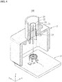
- FIG. 1 is a partially exploded perspective view illustrating a connector assembly in which a housing assembly and a head assembly are separate according to an example embodiment
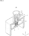
- FIG. 2 is a partially exploded perspective view illustrating the connector assembly in which the housing assembly and the head assembly are connected according to an example embodiment.
- a connector assembly 100 may include a head assembly 1 and a housing assembly 2 connected in a floating structure.
- Other elements of the connector assembly 100 for example, an image sensor and the like, are omitted from the drawings for ease of description.
- the head assembly 1 may be mounted on a printed circuit board (PCB) P.
- the head assembly 1 may be soldered to the PCB P.
- the head assembly 1 may electrically connect the image sensor and the PCB P.
- the PCB P may have a shape corresponding to an inner space of the housing assembly 2.
- the PCB P may be inserted into inner walls of the housing assembly 2.
- the PCB P may slide along the inner walls of the housing assembly 2.
- the head assembly 1 and the housing assembly 2 may be connected.
- the head assembly 1 and the housing assembly 2 may be separate.
- upward and downward may refer to a z-axial direction of coordinate axes illustrated in FIGS. 1 and 2 .
- the housing assembly 2 may include a housing body 21, a housing shell 22, a dielectric 23, a center pin 24, and a coupler 25.
- the housing body 21 may form an exterior of the housing assembly 2.
- the housing body 21 may have a shape protruding upwardly.
- the other elements of the connector assembly 100 for example, the image sensor (not shown), may be easily connected by means of the protruding shape or part.
- the coupler 25 may be provided on a side portion of the protruding shape of the housing body 21.
- the coupler 25 may prevent separations of the other elements of the connector assembly 100 from the housing body 21.
- FIGS. 1 and 2 illustrate the coupler 25 being a protrusion, the shape of the coupler 25 is not limited thereto.
- the coupler 25 may be a groove or a hole.
- the housing shell 22 may contact a first portion of the head assembly 1.
- the first portion may be a head shell 11, which will be described later.
- the housing shell 22 may be electrically connected to the head assembly 1.
- the housing shell 22 may be disposed in an upper portion of the housing body 21.
- the housing shell 22 may be mounted on an inner side of the protruding shape of the housing body 21.
- the dielectric 23 may be provided on an inner side of the housing shell 22 to support the center pin 24.
- the center pin 24 may contact a second portion of the head assembly 1.
- the second portion may be a socket 13, which will be described later.
- the center pin 24 may electrically connect the other elements of the connector assembly 100, for example, the image sensor (not shown), to the PCB P.
- the center pin 24 may be disposed on the inner side of the housing shell 22 and disposed parallel to a central axis of the housing shell 22.
- the head assembly 1 may include the head shell 11, a head body 12, and the socket 13.
- the head shell 11 may be detachable from the housing shell 22.
- the head shell 11 may form an exterior of the head assembly 1.
- the head shell 11 may include a plurality of branch members 111 disposed around a central axis of the head shell 11 in a circumferential direction, a plurality of support members 112 fixed to a PCB, and a bending member 113 to fix the head body 12.
- the plurality of branch members 111 may be inserted into an inner side of the housing shell 22, and at least one of the plurality of branch members 111 may contact the housing shell 22.
- the plurality of branch members 111 may have a shape bent outward to easily contact the housing shell 22.
- the plurality of support members 112 may include, for example, two support members 112 disposed on opposite sides from the central axis of the head shell 11.
- the head shell 11 may include a plurality of branch grooves 115 formed between the plurality of branch members 111, the plurality of branch grooves 115 including a first portion 115a with a width which increases downward, and a second portion 115b provided at a lower end of the first portion 115a in a round shape recessed downwardly.
- the shape of the branch grooves 115 may reduce a plastic deformation of the plurality of branch members 111.
- the bending member 113 may be a member protruding downwardly.
- the bending member 113 may be bent inward after the head body 12 is mounted on the inner side of the head shell 11.
- the inwardly bent bending member 113 may prevent a separation of the head body 12 from the head shell 11.
- the head body 12 may be mounted on the inner side of the head shell 11.
- a central axis a of the head body 12 may be identical to the central axis of the head shell 11.
- the head body 12 may support the socket 13.
- the head body 12 may include a head side portion 121 to be inserted into inner walls of the head shell 11, a head upper portion 122 formed on an upper side of the head side portion 121, and an insertion groove 125.
- the head upper portion 122 may include, at a center thereof, a hole through which the center pin 24 is inserted.
- the insertion groove 125 may be formed on a lower side of the head side portion 121.
- the socket 13 may be detachable from the head body 12.
- the socket 13 may include a plurality of contact members 131, a fixture 132, and an insertion member 135.
- the fixture 132 may have a shape corresponding to the inner walls of the head body 12 and be fixed to the inner walls of the head body 12.
- the plurality of contact members 131 may be formed of a conductive material which may be electrically connected to the center pin 24, and have a shape bent toward the central axis a of the head body 12.
- the plurality of contact members 131 may include a central portion having a shape bent more inward than an upper portion or a lower portion thereof.
- the plurality of contact members 131 may have elasticity. When an external force is applied to the plurality of contact members 131, the plurality of contact members 131 may be deformed around the fixture 132. While the center pin 24 is inserted into the head assembly 1, the center pin 24 may push the plurality of contact members 131 outward. For example, as shown in FIG.
- the contact members 131 may be deformed outwardly around the fixture 132. Further, as shown in FIG. 4 , even if the center pin 24 is inserted into the head assembly 1 while biased in a y-axial direction, the contact members 131 may be deformed outwardly around the fixture 132.
- the plurality of contact members 131 may be disposed around the central axis a of the head body 12 in a circumferential direction. Although FIGS. 3 through 5 illustrate four contact members 131, the number of the plurality of contact members 131 may be greater than or equal to "4". For example, the plurality of contact members 131 may be disposed at predetermined intervals.
- the plurality of contact members 131 may each include a first extension 1311, a second extension 1312, and a third extension 1313.
- the first extension 1311 may extend upward from the fixture 132 and incline toward the central axis a of the head body 12. That is, a separation distance between the first extension 1311 and the head side portion 121 of the head body 12 may increase toward an upper portion of the first extension 1311.
- the first extension 1311 may be a longitudinal member. The first extension 1311 may enable the center pin 24 and the contact members 131 to easily contact each other even when the center pin 24 is not inserted along the central axis a of the head body 12.
- the second extension 1312 may extend upward from the first extension 1311 and incline toward the inner walls of the head body 12. That is, a separation distance between the second extension 1312 and the central axis a of the head body 12 may increase towards an upper portion of the second extension 1312.
- the second extension 1312 may be a longitudinal member.
- the second extension 1312 may guide the center pin 24 to the central axis a of the head body 12 even when the center pin 24 is not inserted along the central axis a of the head body 12.
- the second extension 1312 may prevent the center pin 24 from being restricted not to be inserted into the inner side of the socket 13 as caught by the contact members 131.
- a connecting portion of the first extension 1311 and the second extension 1312 may be positioned closer to the central axis a of the head body 12 than another portion of the socket 13.
- the connecting portion may contact the center pin 24.
- the connecting portion may contact the contact members 131 and the center pin 24 may be electrically connected.
- the connecting portion is shown in the top view of the head assembly 1. Referring to the top view of the head assembly 1, connecting portions may be arranged densely. A distance between connecting portions of adj acent contact members 131 may be less than a width of the center pin 24. Thus, even when the center pin 24 is inserted out of alignment with the central axis a of the head body 12, at least one of the plurality of contact members 131 may contact the center pin 24.
- the third extension 1313 may extend upward from the second extension 1312 and incline in a direction from the second extension 1312 toward the central axis a of the head body 12. That is, the third extension 1313 may be construed as inclining toward the central axis a of the head body 12 with respect to a virtual extension line of the second extension 1312. A separation distance between an upper end of the third extension 1313 and the central axis a of the head body 12 may be greater than or equal to a separation distance between a lower end of the third extension 1313 and the central axis a of the head body 12. For example, the third extension 1313 may become closer to the inner walls of the head body 12 from the lower end toward the upper end thereof.
- the third extension 1313 may be parallel to the inner walls of the head body 12. In an example in which the third extension 1313 is not formed, a sharp end portion of the second extension 1312 may contact inner side walls of the head body 12 and damage the inner walls of the head body 12. However, in an example in which the third extension 1313 is formed as shown in FIG. 3 , such a concern may be prevented. Further, when compared to an example in which the second extension 1312 extends to a height of the third extension 1313, the third extension 1313 may increase a range of angle within which the contact members 131 are deformed around the fixture 132. That is, when designing the contact members 131 to have a predetermined range of deformation angle, a width of an inner space of the head body 12 may be reduced. Thus, by reducing an overall size of the head body 12 or conversely, by increasing a thickness of the head body 12, a strength of the head body 12 may improve.
- the third extension 1313 may be positioned closer to the central axis a of the head body 12 than the fixture 132. By the above structure, it is possible to design the third extension 1313 not to contact the inner walls of the head body 12 even when the contact members 131 are deformed outwardly.
- the upper end of the third extension 1313 may be spaced apart from upper inner walls of the head body 12 by a distance L.
- the third extension 1313 may be prevented from being interfered by the upper inner walls of the head body 12 while the contact members 131 are deformed outwardly.
- the upper end of the third extension 1313 may approach the upper inner walls of the head body 12.
- An inner side of the third extension 1313 may be closer to the central axis a of the head body 12 than an inner side of the head body 12.
- the inner side of the head body 12 may refer to an inner side of the head upper portion 122.
- the inner side of the third extension 1313 may be closer to the central axis a of the head body 12 than the inner side of the head body 12 by a distance d.
- the third extension 1313 may stably guide the center pin 24 to the inner side of the socket 13.
- the insertion member 135 may be formed on a lower side of the fixture 132.
- the insertion member 135 may extend toward a lower portion of the fixture 132 and be bent outward two times, thereby having a shape parallel to the fixture 132.
- the insertion member 135 may be inserted into the insertion groove 125.
- the socket 13 may be stably mounted on the head body 12.
- a suction cap c may be mounted on the upper portion of the head assembly 1, as necessary.
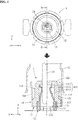
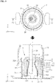
- FIG. 3 illustrates a state in which the center pin 24 is connected to the socket 13 while offset from the central axis a of the head body 12
- FIG. 5 illustrates a state in which the center pin 24 is connected to the socket 13 along the central axis a of the head body 12.
- a distance between center pins 24 facing each other may be less than a diameter D2 of the center pin 24.
- the center pin 24 When the center pin 24 is connected to the socket 13 while offset from the central axis a of the head body 12, the center pin 24 may contact at least two of the at least four contact members 131.
- the at least two contact members 131 may be contact members adjacent to each other.
- the center pin 24 when the center pin 24 is offset in a direction of -x, the center pin 24 may be spaced apart from the contact members 131 disposed in a direction of +x. Even in this example, the center pin 24 may contact the contact members 131 disposed in the direction of -x, a direction of +y, and a direction of -y.
- an electrical connection between the center pin 24 and the socket 13 may be stably implemented.
- the center pin 24 When the center pin 24 is connected to the socket 13 at a regular position, the center pin 24 may contact all the at least four contact members 131. Further, when the center pin 24 is offset in an x-axial direction or a y-axial direction, the center pin 24 may contact at least three contact members 131. In addition, when the center pin 24 is offset between the x-axial direction and the y-axial direction, the center pin 24 may contact at least two contact members 131.
- a distance D1 between two adjacent contact members 131 among the at least four contact members 131 may be less than the diameter D2 of the center pin 24.
- the center pin 24 may be stably connected to the two adjacent contact members 131.
- the head body 12 may include a circular entrance 122a to receive the center pin 24 therethrough.
- the center pin 24 may pass through the entrance 122a and be connected to the socket 13.
- a radius R of the entrance 122a may be greater than or equal to a sum of a radius of the center pin 24, that is, a half of D2, and a maximum offset length of the center pin 24.
- An offset distance or length D3 of the center pin 24 may be determined to be a distance between a central axis of the center pin 24 and the central axis a of the head body 12.
- the maximum offset length may refer to a maximum distance by which the center pin 24 can be structurally spaced apart from the central axis a of the head body 12 while the head assembly 1 is connected to the housing assembly 2 (refer to FIG.
- the radius R of the entrance 122a may be greater than or equal to the sum of the radius of the center pin 24, that is, a half of D2, and the maximum offset length of the center pin 24, the center pin 24 may not be caught by the entrance 122a even when maximally offset.
- the head shell 11 when the housing assembly 2 and the head assembly 1 are connected, the head shell 11 may be disposed on an inner side of the housing shell 22.
- the distance between the head shell 11 and the head body 12 may be greater than or equal to the maximum offset length of the center pin 24.
- the head shell 11 may not contact the head body 12 even when the center pin 24 is maximally offset, and thus a possible offset length of the center pin 24 may not be limited.
- the method of manufacturing a socket for a connector assembly may include operation 920 of forming a plurality of contact members by cutting a plate, operation 930 of bending the cut plate along a plurality of bending lines, and operation 940 of bonding a left end portion and a right end portion of the plate.
- FIG. 8 a shape of a plate 139 before cutting is indicated with broken lines, and the plurality of bending lines is indicated with chain lines.
- the plate 139 having a planar shape may be cut to form the plurality of contact members 131, the fixture 132, and the insertion member 135. Cutting of the plate having the planar shape may be easier than cutting of a three-dimensional (3D) shape.
- the cut plate 139 may be bent along a plurality of bending lines 81, 82, 83, 84, and 85.
- the plurality of bending lines 81, 82, 83, 84, and 85 may include first through third bending lines 81, 82, and 83 to form the plurality of contact members 131, and fourth and fifth bending lines 84 and 85 to form the insertion member 135.
- the plate 139 may be bent along the first bending line 81 in a first direction to form the first extension 1311.
- the plate 139 may be bent along the second bending line 82 in a second direction to form the second extension 1312.
- the second direction may be opposite to the first direction.
- the plate 139 may be bent again along the third bending line 83 in the first direction to form the third extension 1313.
- the plate 139 may be bent along the fourth bending line 84 and the fifth bending line 85 to form the insertion member 135.
- the left end portion and the right end portion of the plate 139 may be bonded by rolling the plate 139.
- a left end portion 132a and a right end portion 132b of the fixture 132 may contact each other.
- the method of manufacturing a socket for a connector assembly may further include, for example, before the plate 139 is cut, operation 910 of bending the plate 139 along the the plurality of bending lines 81, 82, 83, 84, and 85.
- the plate 139 having the planar shape may be bent along the plurality of bending lines 81, 82, 83, 84, and 85.
- the plurality of bending lines 81, 82, 83, 84, and 85 may include the first through third bending lines 81, 82, and 83 to form the plurality of contact members 131, and the fourth and fifth bending lines 84 and 85 to form the insertion member 135.
- the plate 139 may then be flattened prior to the cutting operation 920.
- the plate 139 being unfolded may be cut to form the plurality of contact members 131, the fixture 132, and the insertion member 135. Since a bent plate 139 is not easy to cut, the plate 139 may be cut while unfolded for easy work. The plate may also be cut prior to any bending along the bending lines.
- the cut plate 139 may be bent along the plurality of bending lines.
- the cut plate 139 may be bent again along the bending lines along which the plate 139 was bent in operation 910. Since the plate 139 was already bent one time, the plate 130 may be easily bent with less force.
- the left end portion and the right end portion of the plate 139 may be bonded by rolling the plate 139.
- the left end portion 132a and the right end portion 132b of the fixture 132 may contact each other.
- the first extension 1311 may have a shape which gradually narrows upwardly. The above shape may prevent an overlap between adjacent contact members 131 even when the plurality of contact members 131 converge upwardly towards the central axis of the head body 12.
- a head assembly 3 may include a head shell 31, a head body 32, and a socket 33.
- the head shell 31 may include a plurality of branch members 311, a plurality of support members 312, and a bending member 313.
- the head body 32 may include a head side portion 321, a head upper portion 322, and an insertion groove 325.
- the socket 33 may include a plurality of contact members 331, a fixture 332, and an insertion member 335.
- the plurality of contact members 331 may include a first extension 3311, a second extension 3312, and a third extension 3313. Six contact members 331 may be disposed around a central axis a of the head body 32 in a circumferential direction.
- the first extension 3311 may have a shape which gradually narrows upwardly
- the second extension 3312 may have a shape which gradually broadens or diverges upwardly.
- the plurality of contact members 331 may have a width which decreases as approaching the central axis a of the head body 32.
- a connecting portion of the first extension 3311 and the second extension 3312 may be a portion with a smallest width among the contact members 331.
- the contact members 331 may converge in a direction away from the fixture 332.
- the contact members may each taper in a direction away from the fixture 332.
Description
- One or more example embodiments of the invention relate to a connector assembly.
- A connector assembly may be used for mechanical and electrical connections between constituent elements of various modules. For example, the connector assembly may be used for a camera module. A camera module is a module including various types of lenses and electronic components constituting a camera. Tolerances of the components and assembly errors impede an accurate connection of a head assembly attached to a printed circuit board (PCB) to a housing assembly such that performance of the connector assembly decreases or the components are damaged.
JP 2016-039001 A - The invention as defined in
claim 1 provides a connector assembly that may stably connect a head assembly and a housing assembly notwithstanding tolerances of components or assembly errors. - The connector assembly includes a housing assembly including a housing shell, and a center pin disposed on an inner side of the housing shell, and a head assembly including a head shell detachable from the housing shell, a head body fixed to an inner side of the head shell, and a socket to be mounted on the head body, wherein the socket includes at least four contact members disposed around a central axis of the head body in a circumferential direction and which converge towards the central axis of the head body.
- The center pin may contact all of the at least four contact members when connected to the socket along the central axis of the head body, and the center pin may contact at least two of the at least four contact members when connected to the socket while offset from the central axis of the head body.
- A distance between two adjacent contact members among the at least four contact members may be less than a diameter of the center pin.
- The head body may include a circular entrance configured to receive the center pin therethrough, wherein a radius of the entrance may be greater than or equal to a sum of a radius of the center pin and a maximum offset length of the center pin.
- The head shell may be disposed on the inner side of the housing shell when the housing assembly and the head assembly are connected to each other, wherein a distance between the head shell and the head body may be greater than or equal to a maximum offset length of the center pin when the center pin is connected to the socket along the central axis of the head body.
- The head shell may include a plurality of branch members disposed around a central axis of the head shell in a circumferential direction, and a plurality of branch grooves formed between the plurality of branch members, the plurality of branch grooves including a first portion with a width which increases downward, and a second portion provided at a lower end of the first portion in a round shape recessed downward.
- The socket further includes a fixture fixed to an inner wall of the head body, wherein the at least four contact members each include a first extension extending upward from the fixture and inclined towards the central axis of the head body, and a second extension extending upward from the first extension and inclined towards the inner wall of the head body.
- A connecting portion of the first extension and the second extension is positioned closer to the central axis of the head body than another portion of the socket so as to contact the center pin. The connecting portion of the first extension and the second extension may be positioned closer to the central axis of the head body than all other portions of the socket so as to contact the center pin.
- The first extension is provided in a shape which gradually narrows upwardly.
- The at least four contact members may each further include a third extension extending upwards from the second extension and inclined in a direction from the second extension towards the central axis of the head body.
- The third extension may be parallel to the inner wall of the head body.
- The third extension may be positioned closer to the central axis of the head body than the fixture.
- An upper end of the second extension may be spaced apart from an upper inner wall of the head body when the at least four contact members are not pressed or pressurized by the center pin, and the upper end of the second extension may approach the upper inner wall of the head body when the at least four contact members are pressed or pressurized by the center pin.
- An inner side of the third extension may be positioned closer to the central axis of the head body than an inner side of the head body.
- According to example embodiments of the invention, a connector assembly may provide a stable connection between a center pin and a socket even when the center pin is inserted so as to be spaced part from a central axis of a head body as a consequence of the contact members being bent sufficiently inwardly.
- Further, a distance between the plurality of contact members may be greater than a width of the center pin, and thus a contact failure between the center pin and the socket may be prevented.
- In addition, the socket may be arranged compactly in the head body as a result of the two-step bending structure of the contact members.
- These feature will become apparent and more readily appreciated from the following description of example embodiments, taken in conjunction with the accompanying drawings of which:
-
FIG. 1 is a partially exploded perspective view illustrating a connector assembly in which a housing assembly and a head assembly are separate according to an example embodiment; -
FIG. 2 is a partially exploded perspective view illustrating a connector assembly in which a housing assembly and a head assembly are connected according to an example embodiment; -
FIG. 3 is a view illustrating a top and a cross-section of a center pin being connected to a head assembly while biased in an x-axial direction according to an example embodiment; -
FIG. 4 is a view illustrating a top and a cross-section of a center pin being connected to a head assembly while biased in a y-axial direction according to an example embodiment; -
FIG. 5 is a view illustrating a top and a cross-section of a center pin being connected to a head assembly at an accurate position according to an example embodiment; -
FIG. 6 is a perspective view illustrating a process of assembling a head assembly in order according to an example embodiment; -
FIG. 7 is a flowchart illustrating a method of manufacturing a socket for a connector assembly according to an example embodiment; -
FIG. 8 is a development or opened-out view illustrating a socket according to an example embodiment; -
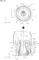
FIG. 9 is a view illustrating a top and a cross-section of a center pin being connected to a head assembly while biased in an x-axial direction according to an example embodiment; -
FIG. 10 is a view illustrating a top and a cross-section of a center pin being connected to a head assembly while biased in a y-axial direction according to an example embodiment; and -
FIG. 11 is a perspective view illustrating a socket according to an example embodiment. - Hereinafter, some example embodiments will be described in detail with reference to the accompanying drawings.
-
FIG. 1 is a partially exploded perspective view illustrating a connector assembly in which a housing assembly and a head assembly are separate according to an example embodiment, andFIG. 2 is a partially exploded perspective view illustrating the connector assembly in which the housing assembly and the head assembly are connected according to an example embodiment. - Referring to
FIGS. 1 and2 , aconnector assembly 100 may include ahead assembly 1 and ahousing assembly 2 connected in a floating structure. Other elements of theconnector assembly 100, for example, an image sensor and the like, are omitted from the drawings for ease of description. - The
head assembly 1 may be mounted on a printed circuit board (PCB) P. For example, thehead assembly 1 may be soldered to the PCB P. Thehead assembly 1 may electrically connect the image sensor and the PCB P. - The PCB P may have a shape corresponding to an inner space of the
housing assembly 2. For example, the PCB P may be inserted into inner walls of thehousing assembly 2. The PCB P may slide along the inner walls of thehousing assembly 2. When the PCB P moves upward along the inner walls of thehousing assembly 2, thehead assembly 1 and thehousing assembly 2 may be connected. When the PCB P moves downward along the inner walls of thehousing assembly 2, thehead assembly 1 and thehousing assembly 2 may be separate. Here, upward and downward may refer to a z-axial direction of coordinate axes illustrated inFIGS. 1 and2 . - The
housing assembly 2 may include ahousing body 21, ahousing shell 22, a dielectric 23, acenter pin 24, and acoupler 25. - The
housing body 21 may form an exterior of thehousing assembly 2. Thehousing body 21 may have a shape protruding upwardly. The other elements of theconnector assembly 100, for example, the image sensor (not shown), may be easily connected by means of the protruding shape or part. Thecoupler 25 may be provided on a side portion of the protruding shape of thehousing body 21. Thecoupler 25 may prevent separations of the other elements of theconnector assembly 100 from thehousing body 21. AlthoughFIGS. 1 and2 illustrate thecoupler 25 being a protrusion, the shape of thecoupler 25 is not limited thereto. For example, thecoupler 25 may be a groove or a hole. - The
housing shell 22 may contact a first portion of thehead assembly 1. For example, the first portion may be ahead shell 11, which will be described later. Thehousing shell 22 may be electrically connected to thehead assembly 1. Thehousing shell 22 may be disposed in an upper portion of thehousing body 21. For example, thehousing shell 22 may be mounted on an inner side of the protruding shape of thehousing body 21. - The dielectric 23 may be provided on an inner side of the
housing shell 22 to support thecenter pin 24. - The
center pin 24 may contact a second portion of thehead assembly 1. For example, the second portion may be asocket 13, which will be described later. Thecenter pin 24 may electrically connect the other elements of theconnector assembly 100, for example, the image sensor (not shown), to the PCB P. Thecenter pin 24 may be disposed on the inner side of thehousing shell 22 and disposed parallel to a central axis of thehousing shell 22. - Referring to
FIGS. 3 through 6 , thehead assembly 1 may include thehead shell 11, ahead body 12, and thesocket 13. - The
head shell 11 may be detachable from thehousing shell 22. Thehead shell 11 may form an exterior of thehead assembly 1. Thehead shell 11 may include a plurality ofbranch members 111 disposed around a central axis of thehead shell 11 in a circumferential direction, a plurality ofsupport members 112 fixed to a PCB, and a bendingmember 113 to fix thehead body 12. The plurality ofbranch members 111 may be inserted into an inner side of thehousing shell 22, and at least one of the plurality ofbranch members 111 may contact thehousing shell 22. The plurality ofbranch members 111 may have a shape bent outward to easily contact thehousing shell 22. The plurality ofsupport members 112 may include, for example, twosupport members 112 disposed on opposite sides from the central axis of thehead shell 11. - The
head shell 11 may include a plurality ofbranch grooves 115 formed between the plurality ofbranch members 111, the plurality ofbranch grooves 115 including afirst portion 115a with a width which increases downward, and asecond portion 115b provided at a lower end of thefirst portion 115a in a round shape recessed downwardly. The shape of thebranch grooves 115 may reduce a plastic deformation of the plurality ofbranch members 111. - The bending
member 113 may be a member protruding downwardly. The bendingmember 113 may be bent inward after thehead body 12 is mounted on the inner side of thehead shell 11. The inwardly bent bendingmember 113 may prevent a separation of thehead body 12 from thehead shell 11. - The
head body 12 may be mounted on the inner side of thehead shell 11. A central axis a of thehead body 12 may be identical to the central axis of thehead shell 11. Thehead body 12 may support thesocket 13. Thehead body 12 may include ahead side portion 121 to be inserted into inner walls of thehead shell 11, a headupper portion 122 formed on an upper side of thehead side portion 121, and aninsertion groove 125. The headupper portion 122 may include, at a center thereof, a hole through which thecenter pin 24 is inserted. Theinsertion groove 125 may be formed on a lower side of thehead side portion 121. - The
socket 13 may be detachable from thehead body 12. Thesocket 13 may include a plurality ofcontact members 131, afixture 132, and aninsertion member 135. - The
fixture 132 may have a shape corresponding to the inner walls of thehead body 12 and be fixed to the inner walls of thehead body 12. - The plurality of
contact members 131 may be formed of a conductive material which may be electrically connected to thecenter pin 24, and have a shape bent toward the central axis a of thehead body 12. For example, the plurality ofcontact members 131 may include a central portion having a shape bent more inward than an upper portion or a lower portion thereof. The plurality ofcontact members 131 may have elasticity. When an external force is applied to the plurality ofcontact members 131, the plurality ofcontact members 131 may be deformed around thefixture 132. While thecenter pin 24 is inserted into thehead assembly 1, thecenter pin 24 may push the plurality ofcontact members 131 outward. For example, as shown inFIG. 3 , if thecenter pin 24 is inserted into thehead assembly 1 while biased in an x-axial direction, thecontact members 131 may be deformed outwardly around thefixture 132. Further, as shown inFIG. 4 , even if thecenter pin 24 is inserted into thehead assembly 1 while biased in a y-axial direction, thecontact members 131 may be deformed outwardly around thefixture 132. - The plurality of
contact members 131 may be disposed around the central axis a of thehead body 12 in a circumferential direction. AlthoughFIGS. 3 through 5 illustrate fourcontact members 131, the number of the plurality ofcontact members 131 may be greater than or equal to "4". For example, the plurality ofcontact members 131 may be disposed at predetermined intervals. The plurality ofcontact members 131 may each include afirst extension 1311, asecond extension 1312, and athird extension 1313. - The
first extension 1311 may extend upward from thefixture 132 and incline toward the central axis a of thehead body 12. That is, a separation distance between thefirst extension 1311 and thehead side portion 121 of thehead body 12 may increase toward an upper portion of thefirst extension 1311. Thefirst extension 1311 may be a longitudinal member. Thefirst extension 1311 may enable thecenter pin 24 and thecontact members 131 to easily contact each other even when thecenter pin 24 is not inserted along the central axis a of thehead body 12. - The
second extension 1312 may extend upward from thefirst extension 1311 and incline toward the inner walls of thehead body 12. That is, a separation distance between thesecond extension 1312 and the central axis a of thehead body 12 may increase towards an upper portion of thesecond extension 1312. Thesecond extension 1312 may be a longitudinal member. Thesecond extension 1312 may guide thecenter pin 24 to the central axis a of thehead body 12 even when thecenter pin 24 is not inserted along the central axis a of thehead body 12. Thesecond extension 1312 may prevent thecenter pin 24 from being restricted not to be inserted into the inner side of thesocket 13 as caught by thecontact members 131. - A connecting portion of the
first extension 1311 and thesecond extension 1312 may be positioned closer to the central axis a of thehead body 12 than another portion of thesocket 13. The connecting portion may contact thecenter pin 24. Through the connecting portion, thecontact members 131 and thecenter pin 24 may be electrically connected. The connecting portion is shown in the top view of thehead assembly 1. Referring to the top view of thehead assembly 1, connecting portions may be arranged densely. A distance between connecting portions of adj acentcontact members 131 may be less than a width of thecenter pin 24. Thus, even when thecenter pin 24 is inserted out of alignment with the central axis a of thehead body 12, at least one of the plurality ofcontact members 131 may contact thecenter pin 24. - The
third extension 1313 may extend upward from thesecond extension 1312 and incline in a direction from thesecond extension 1312 toward the central axis a of thehead body 12. That is, thethird extension 1313 may be construed as inclining toward the central axis a of thehead body 12 with respect to a virtual extension line of thesecond extension 1312. A separation distance between an upper end of thethird extension 1313 and the central axis a of thehead body 12 may be greater than or equal to a separation distance between a lower end of thethird extension 1313 and the central axis a of thehead body 12. For example, thethird extension 1313 may become closer to the inner walls of thehead body 12 from the lower end toward the upper end thereof. In another example, thethird extension 1313 may be parallel to the inner walls of thehead body 12. In an example in which thethird extension 1313 is not formed, a sharp end portion of thesecond extension 1312 may contact inner side walls of thehead body 12 and damage the inner walls of thehead body 12. However, in an example in which thethird extension 1313 is formed as shown inFIG. 3 , such a concern may be prevented. Further, when compared to an example in which thesecond extension 1312 extends to a height of thethird extension 1313, thethird extension 1313 may increase a range of angle within which thecontact members 131 are deformed around thefixture 132. That is, when designing thecontact members 131 to have a predetermined range of deformation angle, a width of an inner space of thehead body 12 may be reduced. Thus, by reducing an overall size of thehead body 12 or conversely, by increasing a thickness of thehead body 12, a strength of thehead body 12 may improve. - The
third extension 1313 may be positioned closer to the central axis a of thehead body 12 than thefixture 132. By the above structure, it is possible to design thethird extension 1313 not to contact the inner walls of thehead body 12 even when thecontact members 131 are deformed outwardly. - When the
contact members 131 are not pressurized or pressed by thecenter pin 24, the upper end of thethird extension 1313 may be spaced apart from upper inner walls of thehead body 12 by a distance L. By the above structure, thethird extension 1313 may be prevented from being interfered by the upper inner walls of thehead body 12 while thecontact members 131 are deformed outwardly. When thecontact members 131 are pressurized or pressed by thecenter pin 24, the upper end of thethird extension 1313 may approach the upper inner walls of thehead body 12. - An inner side of the
third extension 1313 may be closer to the central axis a of thehead body 12 than an inner side of thehead body 12. Here, the inner side of thehead body 12 may refer to an inner side of the headupper portion 122. For example, the inner side of thethird extension 1313 may be closer to the central axis a of thehead body 12 than the inner side of thehead body 12 by a distance d. By the above structure, thethird extension 1313 may stably guide thecenter pin 24 to the inner side of thesocket 13. - The
insertion member 135 may be formed on a lower side of thefixture 132. Theinsertion member 135 may extend toward a lower portion of thefixture 132 and be bent outward two times, thereby having a shape parallel to thefixture 132. Theinsertion member 135 may be inserted into theinsertion groove 125. As theinsertion member 135 is inserted into theinsertion groove 125, thesocket 13 may be stably mounted on thehead body 12. - A suction cap c may be mounted on the upper portion of the
head assembly 1, as necessary. -
FIG. 3 illustrates a state in which thecenter pin 24 is connected to thesocket 13 while offset from the central axis a of thehead body 12, andFIG. 5 illustrates a state in which thecenter pin 24 is connected to thesocket 13 along the central axis a of thehead body 12. - A distance between center pins 24 facing each other may be less than a diameter D2 of the
center pin 24. When thecenter pin 24 is connected to thesocket 13 along the central axis a of thehead body 12, thecenter pin 24 may contact all of the at least fourcontact members 131. Since thecenter pin 24 maintains the contact with all of the at least fourcontact members 131, electrical connections between thecenter pin 24 and thecontact members 131 may be stably guaranteed. - When the
center pin 24 is connected to thesocket 13 while offset from the central axis a of thehead body 12, thecenter pin 24 may contact at least two of the at least fourcontact members 131. The at least twocontact members 131 may be contact members adjacent to each other. In the example ofFIG. 3 , when thecenter pin 24 is offset in a direction of -x, thecenter pin 24 may be spaced apart from thecontact members 131 disposed in a direction of +x. Even in this example, thecenter pin 24 may contact thecontact members 131 disposed in the direction of -x, a direction of +y, and a direction of -y. - As the number of
contact members 131 in contact with thecenter pin 24 increases, an electrical connection between thecenter pin 24 and thesocket 13 may be stably implemented. When thecenter pin 24 is connected to thesocket 13 at a regular position, thecenter pin 24 may contact all the at least fourcontact members 131. Further, when thecenter pin 24 is offset in an x-axial direction or a y-axial direction, thecenter pin 24 may contact at least threecontact members 131. In addition, when thecenter pin 24 is offset between the x-axial direction and the y-axial direction, thecenter pin 24 may contact at least twocontact members 131. - Meanwhile, a distance D1 between two
adjacent contact members 131 among the at least fourcontact members 131 may be less than the diameter D2 of thecenter pin 24. Thus, even when thecenter pin 24 is offset between the twoadjacent contact members 131, thecenter pin 24 may be stably connected to the twoadjacent contact members 131. - The
head body 12 may include acircular entrance 122a to receive thecenter pin 24 therethrough. Thecenter pin 24 may pass through theentrance 122a and be connected to thesocket 13. A radius R of theentrance 122a may be greater than or equal to a sum of a radius of thecenter pin 24, that is, a half of D2, and a maximum offset length of thecenter pin 24. An offset distance or length D3 of thecenter pin 24 may be determined to be a distance between a central axis of thecenter pin 24 and the central axis a of thehead body 12. Here, the maximum offset length may refer to a maximum distance by which thecenter pin 24 can be structurally spaced apart from the central axis a of thehead body 12 while thehead assembly 1 is connected to the housing assembly 2 (refer toFIG. 1 ). Since the radius R of theentrance 122a may be greater than or equal to the sum of the radius of thecenter pin 24, that is, a half of D2, and the maximum offset length of thecenter pin 24, thecenter pin 24 may not be caught by theentrance 122a even when maximally offset. - Meanwhile, when the
housing assembly 2 and thehead assembly 1 are connected, thehead shell 11 may be disposed on an inner side of thehousing shell 22. When thecenter pin 24 is connected to thesocket 13 along the central axis a of thehead body 12, the distance between thehead shell 11 and thehead body 12 may be greater than or equal to the maximum offset length of thecenter pin 24. By the above structure, thehead shell 11 may not contact thehead body 12 even when thecenter pin 24 is maximally offset, and thus a possible offset length of thecenter pin 24 may not be limited. - Referring to
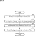
FIGS. 7 and8 , the method of manufacturing a socket for a connector assembly may includeoperation 920 of forming a plurality of contact members by cutting a plate,operation 930 of bending the cut plate along a plurality of bending lines, andoperation 940 of bonding a left end portion and a right end portion of the plate. - In
FIG. 8 , a shape of aplate 139 before cutting is indicated with broken lines, and the plurality of bending lines is indicated with chain lines. - In
operation 920, theplate 139 having a planar shape may be cut to form the plurality ofcontact members 131, thefixture 132, and theinsertion member 135. Cutting of the plate having the planar shape may be easier than cutting of a three-dimensional (3D) shape. - In
operation 930, thecut plate 139 may be bent along a plurality of bendinglines lines third bending lines contact members 131, and fourth andfifth bending lines insertion member 135. - The
plate 139 may be bent along thefirst bending line 81 in a first direction to form thefirst extension 1311. Theplate 139 may be bent along thesecond bending line 82 in a second direction to form thesecond extension 1312. The second direction may be opposite to the first direction. Theplate 139 may be bent again along the third bending line 83 in the first direction to form thethird extension 1313. Through bending theplate 139 three times, thefirst extension 1311, thesecond extension 1312, and thethird extension 1313 of each of the plurality ofcontact members 131 may be formed, whereby the work may be performed quickly. Similarly, theplate 139 may be bent along thefourth bending line 84 and thefifth bending line 85 to form theinsertion member 135. - In
operation 940, the left end portion and the right end portion of theplate 139 may be bonded by rolling theplate 139. For example, aleft end portion 132a and aright end portion 132b of thefixture 132 may contact each other. - The method of manufacturing a socket for a connector assembly may further include, for example, before the
plate 139 is cut,operation 910 of bending theplate 139 along the the plurality of bendinglines - In
operation 910, theplate 139 having the planar shape may be bent along the plurality of bendinglines lines third bending lines contact members 131, and the fourth andfifth bending lines insertion member 135. Theplate 139 may then be flattened prior to thecutting operation 920. - In
operation 920, theplate 139 being unfolded may be cut to form the plurality ofcontact members 131, thefixture 132, and theinsertion member 135. Since abent plate 139 is not easy to cut, theplate 139 may be cut while unfolded for easy work. The plate may also be cut prior to any bending along the bending lines. - In
operation 930, thecut plate 139 may be bent along the plurality of bending lines. Thecut plate 139 may be bent again along the bending lines along which theplate 139 was bent inoperation 910. Since theplate 139 was already bent one time, the plate 130 may be easily bent with less force. - In
operation 940, the left end portion and the right end portion of theplate 139 may be bonded by rolling theplate 139. For example, theleft end portion 132a and theright end portion 132b of thefixture 132 may contact each other. - Referring to
FIG. 8 , thefirst extension 1311 may have a shape which gradually narrows upwardly. The above shape may prevent an overlap betweenadjacent contact members 131 even when the plurality ofcontact members 131 converge upwardly towards the central axis of thehead body 12. - Referring to
FIGS. 9 through 11 , ahead assembly 3 may include ahead shell 31, ahead body 32, and asocket 33. Thehead shell 31 may include a plurality ofbranch members 311, a plurality ofsupport members 312, and a bendingmember 313. Thehead body 32 may include ahead side portion 321, a headupper portion 322, and aninsertion groove 325. Thesocket 33 may include a plurality ofcontact members 331, afixture 332, and aninsertion member 335. - The plurality of
contact members 331 may include afirst extension 3311, asecond extension 3312, and athird extension 3313. Sixcontact members 331 may be disposed around a central axis a of thehead body 32 in a circumferential direction. Thefirst extension 3311 may have a shape which gradually narrows upwardly, and thesecond extension 3312 may have a shape which gradually broadens or diverges upwardly. The plurality ofcontact members 331 may have a width which decreases as approaching the central axis a of thehead body 32. For example, a connecting portion of thefirst extension 3311 and thesecond extension 3312 may be a portion with a smallest width among thecontact members 331. Thecontact members 331 may converge in a direction away from thefixture 332. The contact members may each taper in a direction away from thefixture 332. - A number of example embodiments have been described above. Nevertheless, it should be understood that various modifications may be made to these example embodiments within the scope of the appended claims.
Claims (11)
- A connector assembly (100) comprising:a housing assembly (2) including a housing shell (22), and a center pin (24) disposed on an inner side of the housing shell (22); anda head assembly (1) including a head shell (11) detachable from the housing shell (22), a head body (12) fixed to an inner side of the head shell (11), and a socket (13) to be mounted on the head body (12),wherein the socket (13) includes at least four contact members (131) disposed around a central axis (a) of the head body (12) in a circumferential direction and which converge towards the central axis (a) of the head body (12),wherein the socket (13) further includes a fixture (132) fixed to an inner wall of the head body (12),wherein the at least four contact members (131) each include:a first extension (1311) extending upward from the fixture (132) and inclining towards the central axis (a) of the head body (12); anda second extension (1312) extending upward from the first extension (1311) and inclining towards an inner wall of the head body (12),wherein a connecting portion of the first extension (1311) and the second extension (1312) is positioned closer to the central axis (a) of the head body (12) than another portion of the socket (13) so as to contact the center pin (24),characterised in that the first extension (1311) is provided with a shape which gradually narrows upwardly.
- The connector assembly (100) of claim 1, wherein the center pin (24) contacts all of the at least four contact members (131) when connected to the socket (13) along the central axis (a) of the head body (12),
and the center pin (24) contacts at least two of the at least four contact members (131) when connected to the socket (13) while offset from the central axis (a) of the head body (12). - The connector assembly (100) of claim 1 or 2, wherein a distance (D1) between two adjacent contact members (131) is less than a diameter (D2) of the center pin (24).
- The connector assembly (100) of any preceding claim, wherein the head body (12) includes a circular entrance (122a) configured to receive the center pin (24) therethrough,
wherein a radius (R) of the entrance (122a) is greater than or equal to a sum of a radius of the center pin (24) and a maximum offset distance (D3) of the center pin (24). - The connector assembly (100) of claim 1, wherein the head shell (11) is disposed on the inner side of the housing shell (22) when the housing assembly (2) and the head assembly (1) are connected to each other,
wherein a distance between the head shell (11) and the head body (12) is greater than or equal to a maximum offset distance (D3) of the center pin (24) when the center pin (24) is connected to the socket (13) along the central axis (a) of the head body (12). - The connector assembly (100) of any preceding claim, wherein the head shell (11) comprises:a plurality of branch members (111) disposed around a central axis (a) of the head shell (11) in a circumferential direction; anda plurality of branch grooves (115) formed between the plurality of branch members (111), the plurality of branch grooves (115) each including a first portion (115a) with a width which increases downwardly, and a second portion (115b) provided at a lower end of the first portion (115a) having a round shape recessed downwardly.
- The connector assembly (100) of any preceding claim, wherein the at least four contact members (131) each further includes a third extension (1313) extending upward from the second extension (1312) and inclining in a direction from the second extension (1312) towards the central axis (a) of the head body (12).
- The connector assembly (100) of claim 7, wherein the third extension (1313) is parallel to the inner wall of the head body (12).
- The connector assembly (100) of claim 7 or 8, wherein the third extension (1313) is positioned closer to the central axis (a) of the head body (12) than the fixture (132).
- The connector assembly (100) of any one of claims 1 to 6, wherein an upper end of the second extension (1312) is spaced apart from an upper inner wall of the head body (12) when the at least four contact members (131) are not pressed by the center pin (24), and
the upper end of each of the second extensions (1312) is urged towards the upper inner wall of the head body (12) when the corresponding contact member (131) is pressed by the center pin (24). - The connector assembly (100) of claim 9, wherein an inner side of the third extension (1313) is positioned closer to the central axis (a) of the head body (12) than an inner side of the head body (12).
Applications Claiming Priority (2)
| Application Number | Priority Date | Filing Date | Title |
|---|---|---|---|
| KR20170174544 | 2017-12-18 | ||
| KR1020180050202A KR102608751B1 (en) | 2017-12-18 | 2018-04-30 | Connector assembly and manufacturing method of socket for connector assembly |
Publications (3)
| Publication Number | Publication Date |
|---|---|
| EP3499652A2 EP3499652A2 (en) | 2019-06-19 |
| EP3499652A3 EP3499652A3 (en) | 2019-09-11 |
| EP3499652B1 true EP3499652B1 (en) | 2021-08-18 |
Family
ID=64665535
Family Applications (1)
| Application Number | Title | Priority Date | Filing Date |
|---|---|---|---|
| EP18212542.7A Active EP3499652B1 (en) | 2017-12-18 | 2018-12-14 | Connector assembly |
Country Status (2)
| Country | Link |
|---|---|
| US (1) | US10840642B2 (en) |
| EP (1) | EP3499652B1 (en) |
Families Citing this family (3)
| Publication number | Priority date | Publication date | Assignee | Title |
|---|---|---|---|---|
| JP6712376B1 (en) * | 2019-07-22 | 2020-06-24 | Smk株式会社 | Coaxial connector with floating mechanism |
| CN211126359U (en) * | 2019-10-17 | 2020-07-28 | 富士康(昆山)电脑接插件有限公司 | Coaxial connector |
| EP4088876A1 (en) * | 2021-05-12 | 2022-11-16 | Andreas Stihl AG & Co. KG | Hand-held electric power tool |
Family Cites Families (20)
| Publication number | Priority date | Publication date | Assignee | Title |
|---|---|---|---|---|
| US4925403A (en) * | 1988-10-11 | 1990-05-15 | Gilbert Engineering Company, Inc. | Coaxial transmission medium connector |
| US6224407B1 (en) | 1997-12-17 | 2001-05-01 | The Whitaker Corporation | Coaxial switch connector assembly |
| TW560753U (en) * | 2000-10-26 | 2003-11-01 | Hon Hai Prec Ind Co Ltd | Electrical connector |
| US6648653B2 (en) * | 2002-01-04 | 2003-11-18 | Insert Enterprise Co., Ltd. | Super mini coaxial microwave connector |
| JP3761501B2 (en) * | 2002-07-31 | 2006-03-29 | 本多通信工業株式会社 | Coaxial connector and ground pad on which it is mounted |
| US6827608B2 (en) * | 2002-08-22 | 2004-12-07 | Corning Gilbert Inc. | High frequency, blind mate, coaxial interconnect |
| JP2006066384A (en) * | 2004-07-27 | 2006-03-09 | Hosiden Corp | Coaxial connector for board-to-board connection |
| TWM317693U (en) * | 2007-04-13 | 2007-08-21 | Advanced Connectek Inc | Electrical connector |
| JP5178847B2 (en) * | 2009-01-30 | 2013-04-10 | 株式会社フジクラ | RF plug connector, RF receptacle connector, and RF connector |
| US8317539B2 (en) * | 2009-08-14 | 2012-11-27 | Corning Gilbert Inc. | Coaxial interconnect and contact |
| PL2676330T3 (en) * | 2011-02-17 | 2021-11-29 | Corning Optical Communications Rf Llc | Blind mate interconnect and contact |
| JP6100495B2 (en) * | 2012-10-02 | 2017-03-22 | 矢崎総業株式会社 | Female terminal |
| JP5965811B2 (en) * | 2012-10-03 | 2016-08-10 | 矢崎総業株式会社 | connector |
| JP5748111B2 (en) * | 2013-10-10 | 2015-07-15 | 第一精工株式会社 | Coaxial connector device |
| JP5872000B1 (en) * | 2014-08-06 | 2016-03-01 | 日本航空電子工業株式会社 | Coaxial connector |
| JP6041107B2 (en) * | 2014-09-16 | 2016-12-07 | Smk株式会社 | Coaxial connector with floating mechanism |
| CN204349085U (en) * | 2014-10-10 | 2015-05-20 | 康普技术有限责任公司 | A kind of blind low intermodulation radio frequency connector assembly of joining float type |
| JP6183626B2 (en) | 2015-08-04 | 2017-08-23 | Smk株式会社 | Coaxial connector with floating mechanism |
| EP3280010A1 (en) * | 2016-08-04 | 2018-02-07 | Spinner GmbH | Low passive intermodulation rf connector |
| KR102431635B1 (en) | 2016-11-04 | 2022-08-12 | 삼성전자 주식회사 | Adaptive retransmission method and apparatus for latency reduction in wirelss cellular communication system |
-
2018
- 2018-12-14 EP EP18212542.7A patent/EP3499652B1/en active Active
- 2018-12-18 US US16/224,060 patent/US10840642B2/en active Active
Also Published As
| Publication number | Publication date |
|---|---|
| EP3499652A2 (en) | 2019-06-19 |
| US20190190206A1 (en) | 2019-06-20 |
| EP3499652A3 (en) | 2019-09-11 |
| US10840642B2 (en) | 2020-11-17 |
Similar Documents
| Publication | Publication Date | Title |
|---|---|---|
| KR102614627B1 (en) | Connector assembly and manufacturing method of socket for connector assembly | |
| EP3499652B1 (en) | Connector assembly | |
| US8342875B2 (en) | Board-to-board connector having a sidewall portion with a sloped guide surface with cut out | |
| US9935398B2 (en) | Connector | |
| US9106009B2 (en) | Electrical contact and electrical connector assembly including the same | |
| WO2013126189A1 (en) | Connector assembly configured to align communication connectors during a mating operation | |
| TWI530036B (en) | Connectors and performance boards, motherboards, and semiconductor test devices including the connector | |
| WO2009064528A1 (en) | Electrical connector mating guide | |
| EP2945470B1 (en) | Circuit board interconnection architecture | |
| EP3467950B1 (en) | Connector | |
| US8608491B2 (en) | Electrical connector having structure to pre-set solder balls | |
| US9356407B2 (en) | Connector having a terminal with a coupling portion coupling a first portion having a contact point with a second portion | |
| JP2005209501A (en) | Floating type connector | |
| US9118157B2 (en) | Electrical connector | |
| KR101255371B1 (en) | Electric connector for substrate | |
| US20150222064A1 (en) | Receptacle connector, plug connector and connector assembly | |
| US9711877B2 (en) | Plug and connector module | |
| US11011863B2 (en) | Electrical connector | |
| JP7004228B2 (en) | Expandable connector assembly | |
| US20160006152A1 (en) | Card edge connector and card edge connector assembly | |
| CN110611188B (en) | Floating type connecting module and floating type butt joint device with same | |
| CN101599584B (en) | Electrical connector assembly | |
| EP4336661A1 (en) | Electrical connection assembly and electrical connection device | |
| KR20140001551U (en) | Electrical connector and electrical connector assembly | |
| US20230120108A1 (en) | Hybrid card edge connector |
Legal Events
| Date | Code | Title | Description |
|---|---|---|---|
| PUAI | Public reference made under article 153(3) epc to a published international application that has entered the european phase |
Free format text: ORIGINAL CODE: 0009012 |
|
| STAA | Information on the status of an ep patent application or granted ep patent |
Free format text: STATUS: THE APPLICATION HAS BEEN PUBLISHED |
|
| AK | Designated contracting states |
Kind code of ref document: A2 Designated state(s): AL AT BE BG CH CY CZ DE DK EE ES FI FR GB GR HR HU IE IS IT LI LT LU LV MC MK MT NL NO PL PT RO RS SE SI SK SM TR |
|
| AX | Request for extension of the european patent |
Extension state: BA ME |
|
| PUAL | Search report despatched |
Free format text: ORIGINAL CODE: 0009013 |
|
| AK | Designated contracting states |
Kind code of ref document: A3 Designated state(s): AL AT BE BG CH CY CZ DE DK EE ES FI FR GB GR HR HU IE IS IT LI LT LU LV MC MK MT NL NO PL PT RO RS SE SI SK SM TR |
|
| AX | Request for extension of the european patent |
Extension state: BA ME |
|
| RIC1 | Information provided on ipc code assigned before grant |
Ipc: H01R 24/50 20110101ALN20190806BHEP Ipc: H01R 13/631 20060101ALI20190806BHEP Ipc: H01R 13/11 20060101AFI20190806BHEP |
|
| STAA | Information on the status of an ep patent application or granted ep patent |
Free format text: STATUS: REQUEST FOR EXAMINATION WAS MADE |
|
| 17P | Request for examination filed |
Effective date: 20200302 |
|
| RBV | Designated contracting states (corrected) |
Designated state(s): AL AT BE BG CH CY CZ DE DK EE ES FI FR GB GR HR HU IE IS IT LI LT LU LV MC MK MT NL NO PL PT RO RS SE SI SK SM TR |
|
| GRAP | Despatch of communication of intention to grant a patent |
Free format text: ORIGINAL CODE: EPIDOSNIGR1 |
|
| STAA | Information on the status of an ep patent application or granted ep patent |
Free format text: STATUS: GRANT OF PATENT IS INTENDED |
|
| RIC1 | Information provided on ipc code assigned before grant |
Ipc: H01R 24/50 20110101ALN20210308BHEP Ipc: H01R 13/631 20060101ALI20210308BHEP Ipc: H01R 13/11 20060101AFI20210308BHEP |
|
| INTG | Intention to grant announced |
Effective date: 20210325 |
|
| RIC1 | Information provided on ipc code assigned before grant |
Ipc: H01R 24/50 20110101ALN20210315BHEP Ipc: H01R 13/631 20060101ALI20210315BHEP Ipc: H01R 13/11 20060101AFI20210315BHEP |
|
| GRAS | Grant fee paid |
Free format text: ORIGINAL CODE: EPIDOSNIGR3 |
|
| GRAA | (expected) grant |
Free format text: ORIGINAL CODE: 0009210 |
|
| STAA | Information on the status of an ep patent application or granted ep patent |
Free format text: STATUS: THE PATENT HAS BEEN GRANTED |
|
| AK | Designated contracting states |
Kind code of ref document: B1 Designated state(s): AL AT BE BG CH CY CZ DE DK EE ES FI FR GB GR HR HU IE IS IT LI LT LU LV MC MK MT NL NO PL PT RO RS SE SI SK SM TR |
|
| REG | Reference to a national code |
Ref country code: GB Ref legal event code: FG4D |
|
| REG | Reference to a national code |
Ref country code: CH Ref legal event code: EP |
|
| REG | Reference to a national code |
Ref country code: DE Ref legal event code: R096 Ref document number: 602018021968 Country of ref document: DE |
|
| REG | Reference to a national code |
Ref country code: IE Ref legal event code: FG4D Ref country code: AT Ref legal event code: REF Ref document number: 1422467 Country of ref document: AT Kind code of ref document: T Effective date: 20210915 |
|
| REG | Reference to a national code |
Ref country code: LT Ref legal event code: MG9D |
|
| REG | Reference to a national code |
Ref country code: NL Ref legal event code: MP Effective date: 20210818 |
|
| REG | Reference to a national code |
Ref country code: AT Ref legal event code: MK05 Ref document number: 1422467 Country of ref document: AT Kind code of ref document: T Effective date: 20210818 |
|
| PG25 | Lapsed in a contracting state [announced via postgrant information from national office to epo] |
Ref country code: SE Free format text: LAPSE BECAUSE OF FAILURE TO SUBMIT A TRANSLATION OF THE DESCRIPTION OR TO PAY THE FEE WITHIN THE PRESCRIBED TIME-LIMIT Effective date: 20210818 Ref country code: RS Free format text: LAPSE BECAUSE OF FAILURE TO SUBMIT A TRANSLATION OF THE DESCRIPTION OR TO PAY THE FEE WITHIN THE PRESCRIBED TIME-LIMIT Effective date: 20210818 Ref country code: HR Free format text: LAPSE BECAUSE OF FAILURE TO SUBMIT A TRANSLATION OF THE DESCRIPTION OR TO PAY THE FEE WITHIN THE PRESCRIBED TIME-LIMIT Effective date: 20210818 Ref country code: ES Free format text: LAPSE BECAUSE OF FAILURE TO SUBMIT A TRANSLATION OF THE DESCRIPTION OR TO PAY THE FEE WITHIN THE PRESCRIBED TIME-LIMIT Effective date: 20210818 Ref country code: FI Free format text: LAPSE BECAUSE OF FAILURE TO SUBMIT A TRANSLATION OF THE DESCRIPTION OR TO PAY THE FEE WITHIN THE PRESCRIBED TIME-LIMIT Effective date: 20210818 Ref country code: PT Free format text: LAPSE BECAUSE OF FAILURE TO SUBMIT A TRANSLATION OF THE DESCRIPTION OR TO PAY THE FEE WITHIN THE PRESCRIBED TIME-LIMIT Effective date: 20211220 Ref country code: NO Free format text: LAPSE BECAUSE OF FAILURE TO SUBMIT A TRANSLATION OF THE DESCRIPTION OR TO PAY THE FEE WITHIN THE PRESCRIBED TIME-LIMIT Effective date: 20211118 Ref country code: BG Free format text: LAPSE BECAUSE OF FAILURE TO SUBMIT A TRANSLATION OF THE DESCRIPTION OR TO PAY THE FEE WITHIN THE PRESCRIBED TIME-LIMIT Effective date: 20211118 Ref country code: AT Free format text: LAPSE BECAUSE OF FAILURE TO SUBMIT A TRANSLATION OF THE DESCRIPTION OR TO PAY THE FEE WITHIN THE PRESCRIBED TIME-LIMIT Effective date: 20210818 Ref country code: LT Free format text: LAPSE BECAUSE OF FAILURE TO SUBMIT A TRANSLATION OF THE DESCRIPTION OR TO PAY THE FEE WITHIN THE PRESCRIBED TIME-LIMIT Effective date: 20210818 |
|
| PG25 | Lapsed in a contracting state [announced via postgrant information from national office to epo] |
Ref country code: PL Free format text: LAPSE BECAUSE OF FAILURE TO SUBMIT A TRANSLATION OF THE DESCRIPTION OR TO PAY THE FEE WITHIN THE PRESCRIBED TIME-LIMIT Effective date: 20210818 Ref country code: LV Free format text: LAPSE BECAUSE OF FAILURE TO SUBMIT A TRANSLATION OF THE DESCRIPTION OR TO PAY THE FEE WITHIN THE PRESCRIBED TIME-LIMIT Effective date: 20210818 Ref country code: GR Free format text: LAPSE BECAUSE OF FAILURE TO SUBMIT A TRANSLATION OF THE DESCRIPTION OR TO PAY THE FEE WITHIN THE PRESCRIBED TIME-LIMIT Effective date: 20211119 |
|
| PG25 | Lapsed in a contracting state [announced via postgrant information from national office to epo] |
Ref country code: NL Free format text: LAPSE BECAUSE OF FAILURE TO SUBMIT A TRANSLATION OF THE DESCRIPTION OR TO PAY THE FEE WITHIN THE PRESCRIBED TIME-LIMIT Effective date: 20210818 |
|
| PG25 | Lapsed in a contracting state [announced via postgrant information from national office to epo] |
Ref country code: DK Free format text: LAPSE BECAUSE OF FAILURE TO SUBMIT A TRANSLATION OF THE DESCRIPTION OR TO PAY THE FEE WITHIN THE PRESCRIBED TIME-LIMIT Effective date: 20210818 |
|
| REG | Reference to a national code |
Ref country code: DE Ref legal event code: R097 Ref document number: 602018021968 Country of ref document: DE |
|
| PG25 | Lapsed in a contracting state [announced via postgrant information from national office to epo] |
Ref country code: SM Free format text: LAPSE BECAUSE OF FAILURE TO SUBMIT A TRANSLATION OF THE DESCRIPTION OR TO PAY THE FEE WITHIN THE PRESCRIBED TIME-LIMIT Effective date: 20210818 Ref country code: SK Free format text: LAPSE BECAUSE OF FAILURE TO SUBMIT A TRANSLATION OF THE DESCRIPTION OR TO PAY THE FEE WITHIN THE PRESCRIBED TIME-LIMIT Effective date: 20210818 Ref country code: RO Free format text: LAPSE BECAUSE OF FAILURE TO SUBMIT A TRANSLATION OF THE DESCRIPTION OR TO PAY THE FEE WITHIN THE PRESCRIBED TIME-LIMIT Effective date: 20210818 Ref country code: EE Free format text: LAPSE BECAUSE OF FAILURE TO SUBMIT A TRANSLATION OF THE DESCRIPTION OR TO PAY THE FEE WITHIN THE PRESCRIBED TIME-LIMIT Effective date: 20210818 Ref country code: CZ Free format text: LAPSE BECAUSE OF FAILURE TO SUBMIT A TRANSLATION OF THE DESCRIPTION OR TO PAY THE FEE WITHIN THE PRESCRIBED TIME-LIMIT Effective date: 20210818 Ref country code: AL Free format text: LAPSE BECAUSE OF FAILURE TO SUBMIT A TRANSLATION OF THE DESCRIPTION OR TO PAY THE FEE WITHIN THE PRESCRIBED TIME-LIMIT Effective date: 20210818 |
|
| PLBE | No opposition filed within time limit |
Free format text: ORIGINAL CODE: 0009261 |
|
| STAA | Information on the status of an ep patent application or granted ep patent |
Free format text: STATUS: NO OPPOSITION FILED WITHIN TIME LIMIT |
|
| 26N | No opposition filed |
Effective date: 20220519 |
|
| PG25 | Lapsed in a contracting state [announced via postgrant information from national office to epo] |
Ref country code: MC Free format text: LAPSE BECAUSE OF FAILURE TO SUBMIT A TRANSLATION OF THE DESCRIPTION OR TO PAY THE FEE WITHIN THE PRESCRIBED TIME-LIMIT Effective date: 20210818 |
|
| REG | Reference to a national code |
Ref country code: CH Ref legal event code: PL |
|
| PG25 | Lapsed in a contracting state [announced via postgrant information from national office to epo] |
Ref country code: SI Free format text: LAPSE BECAUSE OF FAILURE TO SUBMIT A TRANSLATION OF THE DESCRIPTION OR TO PAY THE FEE WITHIN THE PRESCRIBED TIME-LIMIT Effective date: 20210818 |
|
| REG | Reference to a national code |
Ref country code: BE Ref legal event code: MM Effective date: 20211231 |
|
| PG25 | Lapsed in a contracting state [announced via postgrant information from national office to epo] |
Ref country code: LU Free format text: LAPSE BECAUSE OF NON-PAYMENT OF DUE FEES Effective date: 20211214 Ref country code: IE Free format text: LAPSE BECAUSE OF NON-PAYMENT OF DUE FEES Effective date: 20211214 |
|
| PG25 | Lapsed in a contracting state [announced via postgrant information from national office to epo] |
Ref country code: BE Free format text: LAPSE BECAUSE OF NON-PAYMENT OF DUE FEES Effective date: 20211231 |
|
| PG25 | Lapsed in a contracting state [announced via postgrant information from national office to epo] |
Ref country code: LI Free format text: LAPSE BECAUSE OF NON-PAYMENT OF DUE FEES Effective date: 20211231 Ref country code: CH Free format text: LAPSE BECAUSE OF NON-PAYMENT OF DUE FEES Effective date: 20211231 |
|
| PG25 | Lapsed in a contracting state [announced via postgrant information from national office to epo] |
Ref country code: CY Free format text: LAPSE BECAUSE OF FAILURE TO SUBMIT A TRANSLATION OF THE DESCRIPTION OR TO PAY THE FEE WITHIN THE PRESCRIBED TIME-LIMIT Effective date: 20210818 |
|
| PG25 | Lapsed in a contracting state [announced via postgrant information from national office to epo] |
Ref country code: HU Free format text: LAPSE BECAUSE OF FAILURE TO SUBMIT A TRANSLATION OF THE DESCRIPTION OR TO PAY THE FEE WITHIN THE PRESCRIBED TIME-LIMIT; INVALID AB INITIO Effective date: 20181214 |
|
| GBPC | Gb: european patent ceased through non-payment of renewal fee |
Effective date: 20221214 |
|
| PG25 | Lapsed in a contracting state [announced via postgrant information from national office to epo] |
Ref country code: GB Free format text: LAPSE BECAUSE OF NON-PAYMENT OF DUE FEES Effective date: 20221214 |
|
| PGFP | Annual fee paid to national office [announced via postgrant information from national office to epo] |
Ref country code: IT Payment date: 20231110 Year of fee payment: 6 Ref country code: FR Payment date: 20231009 Year of fee payment: 6 Ref country code: DE Payment date: 20231017 Year of fee payment: 6 |