EP3499540B1 - Electrical device intended to establish or break the current in an electrical circuit - Google Patents
Electrical device intended to establish or break the current in an electrical circuit Download PDFInfo
- Publication number
- EP3499540B1 EP3499540B1 EP18204714.2A EP18204714A EP3499540B1 EP 3499540 B1 EP3499540 B1 EP 3499540B1 EP 18204714 A EP18204714 A EP 18204714A EP 3499540 B1 EP3499540 B1 EP 3499540B1
- Authority
- EP
- European Patent Office
- Prior art keywords
- conductor
- electrical
- contacts
- neutral
- fixed contacts
- Prior art date
- Legal status (The legal status is an assumption and is not a legal conclusion. Google has not performed a legal analysis and makes no representation as to the accuracy of the status listed.)
- Active
Links
- 230000007935 neutral effect Effects 0.000 claims description 34
- 239000004020 conductor Substances 0.000 claims description 33
- 238000011144 upstream manufacturing Methods 0.000 claims description 10
- 238000003780 insertion Methods 0.000 description 5
- 230000037431 insertion Effects 0.000 description 5
- 230000032683 aging Effects 0.000 description 3
- 230000006978 adaptation Effects 0.000 description 2
- 230000004048 modification Effects 0.000 description 2
- 238000012986 modification Methods 0.000 description 2
- 230000006378 damage Effects 0.000 description 1
- 238000010891 electric arc Methods 0.000 description 1
Images


Classifications
-
- H—ELECTRICITY
- H01—ELECTRIC ELEMENTS
- H01H—ELECTRIC SWITCHES; RELAYS; SELECTORS; EMERGENCY PROTECTIVE DEVICES
- H01H50/00—Details of electromagnetic relays
- H01H50/002—Details of electromagnetic relays particular to three-phase electromagnetic relays
-
- H—ELECTRICITY
- H01—ELECTRIC ELEMENTS
- H01H—ELECTRIC SWITCHES; RELAYS; SELECTORS; EMERGENCY PROTECTIVE DEVICES
- H01H50/00—Details of electromagnetic relays
- H01H50/14—Terminal arrangements
-
- H—ELECTRICITY
- H01—ELECTRIC ELEMENTS
- H01H—ELECTRIC SWITCHES; RELAYS; SELECTORS; EMERGENCY PROTECTIVE DEVICES
- H01H50/00—Details of electromagnetic relays
- H01H50/54—Contact arrangements
-
- H—ELECTRICITY
- H01—ELECTRIC ELEMENTS
- H01H—ELECTRIC SWITCHES; RELAYS; SELECTORS; EMERGENCY PROTECTIVE DEVICES
- H01H50/00—Details of electromagnetic relays
- H01H50/54—Contact arrangements
- H01H50/546—Contact arrangements for contactors having bridging contacts
Definitions
- the present invention relates to an electrical apparatus intended to establish or interrupt the current in an electrical circuit, said apparatus comprising at least two pairs of fixed contacts, each pair comprising two fixed contacts electrically connected respectively to an upstream terminal and to a downstream terminal of the apparatus, and associated with this pair of fixed contacts, a bridge of two movable contacts able to be moved between a first position in which it electrically connects these two fixed contacts, and a second position in which the flow of current between these two contacts fixed contacts is interrupted, one of the pairs of fixed contacts and its associated moving contact bridge being on a line carrying a phase, the other or another of the pairs of fixed contacts and its associated moving contact bridge being on a line carrying the neutral.
- contactor is an electrotechnical device intended to establish or interrupt the flow of current by means of an electrical or pneumatic control device.
- this contactor can be unipolar, bipolar, tripolar or even tetrapolar.
- this contactor has one to four power contacts designed to withstand the appearance of an electric arc resulting from a high current on opening or closing.
- a contactor In such a contactor, all the movable contacts are mounted in the same support so as to be able to be moved all at the same time when a closing or opening order is given to the contactor.
- a contactor is capable of being actuated either manually or by means of a coil capable of being traversed by an electric current and of cooperating with a fixed armature integral with the fixed contacts of the contactor and a mobile armature integral with the mobile contacts of the contactor.
- the fixed armature exerts no magnetic attraction on the mobile armature, the magnetic circuit is then open.
- the fixed armature attracts the movable armature and sticks to it: the magnetic circuit is then closed. The movements of the mobile armature therefore cause the opening and closing of the contacts.
- this device comprises a neutral line, being for example of the tetrapolar type comprising three phase lines and a neutral line
- the neutral line is materialized in the same way as the phase line, that is to say that it comprises two fixed contacts electrically connected respectively to the two terminals, and a bridge of movable contacts forming two movable contacts capable of cooperating respectively with the two aforementioned fixed contacts.
- All of these fixed and moving contacts each include a contact pad, which is likely to show signs of aging after a certain number of contactor operations. This phenomenon of aging of the contact pads can lead to breaks in the neutral likely to generate overvoltages, which can lead to partial or total destruction of the loads.
- the installer In order to overcome this problem and to ensure that the electrical connection between the two upstream and downstream terminals on the neutral line is properly made, the installer usually installs as a precaution wired external wiring electrically connecting the two terminals, which represents a constraint for the installer.
- the present invention solves these problems and proposes an electrical device intended to establish or interrupt the current in an electrical circuit, such as a contactor, making it possible to eliminate the risks of breaking the neutral without additional constraints for the installer.
- the present invention relates to an electrical apparatus according to claim 1.
- all the movable contact bridges of the device are mounted in the same support capable of being moved by control means between the two aforementioned positions, each movable contact bridge passing through an opening of the support, so as to able to be driven by the latter, towards the two positions respectively closed and open, the neutral conductor passing through the support through a recess arranged with respect to the conductor in such a way that the conductor does not prevent the movement of the support, the portion crossing of the neutral conductor being in the same plane as the movable contact bridges when these are in the closed position.
- the aforementioned opening allows the insertion of this movable contact bridge parallel to the axis of the movable contact bridge, and the aforementioned recess is able to allow the insertion of the conductor in the support perpendicular to the longitudinal direction of this conductor.
- the aforementioned neutral conductor is held and positioned in at least one slideway provided in the inner face of a wall belonging to the housing of the device.
- this apparatus is of the tetrapolar type comprising three phase electrical lines and one electrical neutral line.
- this device is a contactor.
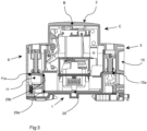
- this contactor C is housed in a housing B of substantially parallelepiped shape comprising a rear face 1 for fixing to a mounting rail, a front face 2 forming a nose, two side faces 3,4 by which the contactor can be attached to other devices of the same type on the rail, and two respectively upper 5 and lower 6 faces comprising respectively a set of downstream terminals A and a set of upstream terminals T.
- this device is of the tetrapolar type and houses four electric lines 7,8,9,10 respectively a neutral line 7 and three phase lines 8,9,10.
- Each of these electric lines is associated with an upstream terminal 11,12,13,14 and a downstream terminal 15,16,17,18, intended to be electrically connected, as regards the upstream terminals, to supply means , and as regards the downstream terminals, to outgoing devices, via cables or a comb.
- Each phase power line 8,9,10 has two fixed contacts 19,20; 21.22; 23,24 electrically connected respectively to a downstream terminal and an upstream terminal, and a bridge of two movable contacts 25,26,27 forming at its two opposite ends two movable contacts a, b respectively intended to cooperate with the two fixed contacts 19,20 to 24. All the contacts comprise at the level of the contact zones, contact pads 28. All the fixed contacts are electrically connected and mechanically by their end located opposite the moving contacts, to the connection pad 12a, 13a, 14a, 16a, 17a, 18a of the corresponding terminal 12, 13, 14, 16, 17, 18.
- the electrical connection between the upstream terminal 11 and the downstream terminal 15 on the neutral line 7 is permanent, and is therefore not equipped, as is the case for the other phase lines, with one movable contact and two fixed contacts.
- this electrical connection consists of a rigid conductor 29 of flattened shape consisting of a single piece.
- This conductor comprises a rectilinear part 29a having at its two opposite ends two folds at right angles 29b, 29c and forms, at its two opposite ends, two parts or connection pads 11a, 15a intended to be introduced respectively into the two corresponding terminals 11 ,15.
- this neutral conductor 29 corresponds globally to that of each assembly associated with a phase current line, and comprising the two fixed contacts, the movable bridge, and the two connection pads.
- the straight part 29a of the neutral conductor 29 is located in the same plane as each assembly comprising two fixed contacts and a movable contact associated with a phase line.
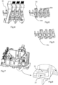
- all the movable contact bridges 25,26,27 of the device are mounted in the same support 30 adapted to be moved by control means of the manual or electromagnetic type, between the two aforementioned positions.
- Each movable contact bridge passes through an opening 30a of the support, so as to be able to be driven by the latter, towards the two positions respectively closed and open, the neutral conductor 29 for its part passing through the support 30 through a recess 30b arranged relative to the driver in such a way that this neutral conductor does not prevent the movement of the support 30, the neutral conductor being in the same plane as the movable contact bridges when the latter are in the closed position.
- This opening 30a allows the insertion of this bridge parallel to the axis of the bridge, while the aforementioned recess 30b is able to allow the insertion of the neutral conductor in the support 30 perpendicular to the longitudinal direction of this conductor.
- the assembly of the neutral conductor is carried out as follows.
- the neutral conductor 29 is placed in two slides 31,32 of the case B of the device illustrated on the figures 7 and 8 , then the two neutral terminals 11,15 are mounted respectively at the two ends of the conductor.
- the support 30 equipped with the movable contact bridges 25,26,27 is placed in the housing of the device until it is located just above the neutral conductor 29, after possible modification of the support 30 , as previously indicated, in the case where a support of the prior art is used. Then, the fixed contacts 19 to 24 are introduced into the housing B as well as the corresponding terminals! 1 to 18.
- an electrical apparatus intended to establish or interrupt the current in an electrical circuit such as a contactor, has been produced, this apparatus making it possible to eliminate the problems of neutral breaks appearing after the aging of the contact pads, without external wiring. wired, using a shunt built into the device on the neutral line.
- This solution can easily be integrated into existing contactors with a minimum of modifications to be made.
Description
La présente invention concerne un appareil électrique destiné à établir ou interrompre le courant dans un circuit électrique, ledit appareil comportant au moins deux paires de contacts fixes, chaque paire comportant deux contacts fixes reliés électriquement respectivement à une borne amont et à une borne aval de l'appareil, et associée à cette paire de contacts fixes, un pont de deux contacts mobiles apte à être déplacé entre une première position dans laquelle il relie électriquement ces deux contacts fixes, et une seconde position dans laquelle la circulation du courant entre ces deux contacts fixes est interrompue, l'une des paires de contacts fixes et son pont de contacts mobiles associé étant sur une ligne véhiculant une phase, l'autre ou une autre des paires de contacts fixes et son pont de contacts mobiles associé étant sur une ligne véhiculant le neutre.The present invention relates to an electrical apparatus intended to establish or interrupt the current in an electrical circuit, said apparatus comprising at least two pairs of fixed contacts, each pair comprising two fixed contacts electrically connected respectively to an upstream terminal and to a downstream terminal of the apparatus, and associated with this pair of fixed contacts, a bridge of two movable contacts able to be moved between a first position in which it electrically connects these two fixed contacts, and a second position in which the flow of current between these two contacts fixed contacts is interrupted, one of the pairs of fixed contacts and its associated moving contact bridge being on a line carrying a phase, the other or another of the pairs of fixed contacts and its associated moving contact bridge being on a line carrying the neutral.
On connaît un tel appareil appelé « contacteur », lequel est un appareil électrotechnique destiné à établir ou interrompre le passage du courant par l'intermédiaire d'un dispositif de commande électrique ou pneumatique.We know such a device called a "contactor", which is an electrotechnical device intended to establish or interrupt the flow of current by means of an electrical or pneumatic control device.
Selon son utilisation, ce contacteur peut être unipolaire, bipolaire, tripolaire ou encore tétra polaire. En d'autres termes, ce contacteur possède d'un à quatre contacts de puissance prévus pour résister à l'apparition d'un arc électrique issu d'un fort courant à l'ouverture ou à la fermeture.Depending on its use, this contactor can be unipolar, bipolar, tripolar or even tetrapolar. In other words, this contactor has one to four power contacts designed to withstand the appearance of an electric arc resulting from a high current on opening or closing.
Dans un tel contacteur, tous les contacts mobiles sont montés dans un même support de manière à pouvoir être déplacés tous en même temps lorsqu'un ordre de fermeture ou bien d'ouverture est donné au contacteur. Un tel contacteur est apte à être actionné soit manuellement, soit par l'intermédiaire d'une bobine apte à être traversée par un courant électrique et à coopérer avec une armature fixe solidaire des contacts fixes du contacteur et une armature mobile solidaire des contacts mobiles du contacteur. Ainsi, lorsque la bobine n'est parcourue par aucun courant électrique, l'armature fixe n'exerce aucune attraction magnétique sur l'armature mobile, le circuit magnétique est alors ouvert. Lorsque la bobine est parcourue par un courant suffisant, l'armature fixe attire l'armature mobile et se colle à celle-ci : le circuit magnétique est alors fermé. Les mouvements de l'armature mobile entraînent donc l'ouverture et la fermeture des contacts.In such a contactor, all the movable contacts are mounted in the same support so as to be able to be moved all at the same time when a closing or opening order is given to the contactor. Such a contactor is capable of being actuated either manually or by means of a coil capable of being traversed by an electric current and of cooperating with a fixed armature integral with the fixed contacts of the contactor and a mobile armature integral with the mobile contacts of the contactor. Thus, when the coil is not traversed by any electric current, the fixed armature exerts no magnetic attraction on the mobile armature, the magnetic circuit is then open. When the coil is traversed by a sufficient current, the fixed armature attracts the movable armature and sticks to it: the magnetic circuit is then closed. The movements of the mobile armature therefore cause the opening and closing of the contacts.
Lorsque cet appareil comporte une ligne de neutre, étant par exemple du type tétra polaire comportant trois lignes de phase et une ligne de neutre, la ligne de neutre est matérialisée de la même manière que la ligne de phase, c'est-à-dire qu'elle comporte deux contacts fixes reliés électriquement respectivement aux deux bornes, et un pont de contacts mobiles formant deux contacts mobiles aptes à coopérer respectivement avec les deux contacts fixes précités.When this device comprises a neutral line, being for example of the tetrapolar type comprising three phase lines and a neutral line, the neutral line is materialized in the same way as the phase line, that is to say that it comprises two fixed contacts electrically connected respectively to the two terminals, and a bridge of movable contacts forming two movable contacts capable of cooperating respectively with the two aforementioned fixed contacts.
Tous ces contacts fixes et mobiles comportent chacun une pastille de contact, laquelle est susceptible de présenter des signes de vieillissement après un certain nombre de manoeuvres du contacteur. Ce phénomène de vieillissement des pastilles de contacts peut entraîner des ruptures de neutre susceptibles de générer des surtensions, lesquelles peuvent entraîner une destruction partielle ou totale des récepteurs.All of these fixed and moving contacts each include a contact pad, which is likely to show signs of aging after a certain number of contactor operations. This phenomenon of aging of the contact pads can lead to breaks in the neutral likely to generate overvoltages, which can lead to partial or total destruction of the loads.
Afin de pallier ce problème et de s'assurer que la liaison électrique entre les deux bornes amont et aval sur la ligne de neutre est bien réalisée, l'installateur a l'habitude de mettre en place par précaution un câblage extérieur filaire reliant électriquement les deux bornes, ce qui représente une contrainte pour l'installateur.In order to overcome this problem and to ensure that the electrical connection between the two upstream and downstream terminals on the neutral line is properly made, the installer usually installs as a precaution wired external wiring electrically connecting the two terminals, which represents a constraint for the installer.
On connaît le document
La présente invention résout ces problèmes et propose un appareil électrique destiné à établir ou interrompre le courant dans un circuit électrique, tel un contacteur, permettant de supprimer les risques de rupture de neutre sans contraintes supplémentaires pour l'installateur.The present invention solves these problems and proposes an electrical device intended to establish or interrupt the current in an electrical circuit, such as a contactor, making it possible to eliminate the risks of breaking the neutral without additional constraints for the installer.
A cet effet, la présente invention a pour objet un appareil électrique selon la revendication 1.To this end, the present invention relates to an electrical apparatus according to
Selon une caractéristique particulière, tous les ponts de contacts mobiles de l'appareil sont montés dans un même support apte à être déplacé par des moyens de commande entre les deux positions précitées, chaque pont de contacts mobiles traversant une ouverture du support, de manière à pouvoir être entraîné par celui-ci, vers les deux positions respectivement fermée et ouverte, le conducteur de neutre traversant le support à travers un évidement agencé par rapport au conducteur de telle manière que le conducteur n'empêche pas le déplacement du support, la portion traversante du conducteur de neutre étant dans le même plan que les ponts de contacts mobiles lorsque ceux-ci sont en position fermée.According to a particular characteristic, all the movable contact bridges of the device are mounted in the same support capable of being moved by control means between the two aforementioned positions, each movable contact bridge passing through an opening of the support, so as to able to be driven by the latter, towards the two positions respectively closed and open, the neutral conductor passing through the support through a recess arranged with respect to the conductor in such a way that the conductor does not prevent the movement of the support, the portion crossing of the neutral conductor being in the same plane as the movable contact bridges when these are in the closed position.
Selon une autre caractéristique, l'ouverture précitée permet l'insertion de ce pont de contacts mobiles parallèlement à l'axe du pont de contacts mobiles, et l'évidement précité est apte à permettre l'insertion du conducteur dans le support perpendiculairement à la direction longitudinale de ce conducteur.According to another characteristic, the aforementioned opening allows the insertion of this movable contact bridge parallel to the axis of the movable contact bridge, and the aforementioned recess is able to allow the insertion of the conductor in the support perpendicular to the longitudinal direction of this conductor.
Selon une autre caractéristique, le conducteur de neutre précité est maintenu et positionné dans au moins une glissière prévue dans la face intérieure d'une paroi appartenant au boîtier de l'appareil.According to another feature, the aforementioned neutral conductor is held and positioned in at least one slideway provided in the inner face of a wall belonging to the housing of the device.
Selon une autre caractéristique, cet appareil est du type tétra polaire comportant trois lignes électriques de phase et une ligne électrique de neutre.According to another characteristic, this apparatus is of the tetrapolar type comprising three phase electrical lines and one electrical neutral line.
Selon une caractéristique particulière, cet appareil est un contacteur.According to a particular characteristic, this device is a contactor.
Mais d'autres avantages et caractéristiques de l'invention apparaîtront mieux dans la description détaillée qui suit et se réfère aux dessins annexés donnés uniquement à titre d'exemple et dans lesquels :
- La
figure 1 est une vue en perspective d'un contacteur selon l'invention, - La
figure 2 est une vue en perspective illustrant une partie du contacteur comportant les bornes et les liaisons électriques reliant les bornes amont aux bornes aval, - La
figure 3 est une vue en coupe du contacteur dans un plan parallèle au plan de fixation de l'appareil, et - La
figure 4 est une vue en perspective illustrant une partie de l'appareil comportant le support de contacts mobiles, les contacts fixes et mobiles, ainsi que le conducteur de neutre selon l'invention, - La
figure 5 est une vue en perspective illustrant un support de contacts mobiles selon l'art antérieur, - La
figure 6 est une vue en perspective du support de contacts mobiles, après adaptation selon l'invention, - La
figure 7 est une vue partielle en perspective, illustrant plus particulièrement la partie du boîtier de l'appareil comportant des glissières, et - La
figure 8 est une vue de détail de la figure précédente.
- There
figure 1 is a perspective view of a contactor according to the invention, - There
figure 2 is a perspective view illustrating part of the contactor comprising the terminals and the electrical connections connecting the upstream terminals to the downstream terminals, - There
picture 3 - There
figure 4 is a perspective view illustrating part of the device comprising the movable contact support, the fixed and movable contacts, as well as the neutral conductor according to the invention, - There
figure 5 is a perspective view illustrating a mobile contact support according to the prior art, - There
figure 6 is a perspective view of the mobile contact support, after adaptation according to the invention, - There
figure 7 is a partial perspective view, illustrating more particularly the part of the device housing comprising slideways, and - There
figure 8 is a detail view of the previous figure.
Sur la
Selon cette réalisation particulière illustrée, cet appareil est du type tétra polaire et loge quatre lignes électriques 7,8,9,10 respectivement une ligne de neutre 7 et trois lignes de phase 8,9,10. A chacune de ces lignes électriques est associée une borne amont 11,12,13,14 et une borne aval 15,16,17,18, destinées à être reliées électriquement, pour ce qui concerne les bornes amont, à des moyens d'alimentation, et pour ce qui concerne les bornes aval, à des appareils de départ, par l'intermédiaire de câbles ou d'un peigne. Chaque ligne électrique de phase 8,9,10 comporte deux contacts fixes 19,20 ; 21,22 ; 23,24 reliés électriquement respectivement à une borne aval et à une borne amont, et un pont de deux contacts mobiles 25,26,27 formant à ses deux extrémités opposées deux contacts mobiles a,b destinés respectivement à coopérer avec les deux contacts fixes 19,20 à 24. Tous les contacts comportent au niveau des zones de contact, des pastilles de contact 28. Tous les contacts fixes sont reliés électriquement et mécaniquement par leur extrémité située à l'opposé des contacts mobiles, à la plage de raccordement 12a,13a,14a,16a,17a,18a de la borne correspondante 12,13,14,16,17,18.According to this particular illustrated embodiment, this device is of the tetrapolar type and houses four
Conformément à l'invention, la liaison électrique entre la borne amont 11 et la borne aval 15 sur la ligne de neutre 7 est permanente, et n'est donc pas équipée, comme ceci est le cas pour les autres lignes de phase, d'un contact mobile et de deux contacts fixes.In accordance with the invention, the electrical connection between the
Selon la réalisation de l'invention illustrée, cette liaison électrique est constituée par un conducteur rigide 29 de forme aplatie constitué d'une seule pièce. Ce conducteur comporte une partie rectiligne 29a présentant à ses deux extrémités opposées deux plis à angle droit 29b, 29c et forme, à ses deux extrémités opposées, deux parties ou plages de raccordement 11a,15a destinées à être introduites respectivement dans les deux bornes correspondantes 11,15.According to the embodiment of the invention illustrated, this electrical connection consists of a
La forme de ce conducteur de neutre 29 correspond globalement à celle de chaque ensemble associé à une ligne de courant de phase, et comportant les deux contacts fixes, le pont mobile, et les deux plages de raccordement. La partie rectiligne 29a du conducteur de neutre 29 est située dans le même plan que chaque ensemble comportant deux contacts fixes et un contact mobile associé à une ligne de phase.The shape of this
Tel qu'illustré sur les
Ainsi, il est possible d'utiliser un support tel que celui utilisé habituellement dans les contacteurs de l'art antérieur, en retirant une partie d'extrémité 30c de celui-ci de manière à permettre l'insertion du conducteur de neutre dans ce support perpendiculairement à sa direction longitudinale.Thus, it is possible to use a support such as that usually used in contactors of the prior art, by removing an
Le montage du conducteur de neutre s'effectue de la manière qui suit.The assembly of the neutral conductor is carried out as follows.
On place tout d'abord le conducteur de neutre 29 dans deux glissières 31,32 du boîtier B de l'appareil illustrées sur les
Puis, le support 30 équipé des ponts de contacts mobiles 25,26,27 est placé dans le boîtier de l'appareil jusqu'à ce qu'il soit situé juste au-dessus du conducteur de neutre 29, après modification éventuelle du support 30, tel que précédemment indiqué, dans le cas où un support de l'art antérieur est utilisé. Puis, les contacts fixes 19 à 24 sont introduits dans le boîtier B ainsi que les bornes correspondantes! 1 à 18.Then, the
On a réalisé grâce à l'invention un appareil électrique destiné à établir ou interrompre le courant dans un circuit électrique, tel un contacteur, cet appareil permettant de supprimer les problèmes des ruptures de neutre apparaissant après le vieillissement des pastilles de contact, sans câblage extérieur filaire, en utilisant un shunt intégré dans l'appareil sur la ligne de neutre. Cette solution est facilement intégrable dans les contacteurs existants avec un minimum de modifications à réaliser.Thanks to the invention, an electrical apparatus intended to establish or interrupt the current in an electrical circuit, such as a contactor, has been produced, this apparatus making it possible to eliminate the problems of neutral breaks appearing after the aging of the contact pads, without external wiring. wired, using a shunt built into the device on the neutral line. This solution can easily be integrated into existing contactors with a minimum of modifications to be made.
Bien entendu, l'invention n'est pas limitée au mode de réalisation décrit et illustré qui n'a été donné qu'à titre d'exemple.Of course, the invention is not limited to the embodiment described and illustrated which has been given by way of example only.
Au contraire, l'invention est limitée par la portée des revendications cijointes. Rather, the invention is limited by the scope of the appended claims.
Claims (6)
- Electrical device intended to establish or break the current in an electrical circuit, said device comprising at least two pairs of fixed contacts, each pair comprising two fixed contacts electrically linked to an upstream terminal and to a downstream terminal, respectively, of the device, and, associated with at least one pair of the at least two pairs of fixed contacts, a bridge of two mobile contacts which can be moved between a first position, in which it electrically links these two fixed contacts, and a second position, in which the flow of current between these two fixed contacts is broken, one of the pairs of fixed contacts and its associated bridge of mobile contacts being on a line carrying a phase, the other or another of the pairs of fixed contacts and an associated electrical link being on a line carrying the neutral, the electrical link between the two terminals (11, 15) situated on the neutral line (7) being a permanent link, the aforementioned electrical link being produced by a single-part rigid conductor (29) comprising, at its two opposite ends, respectively, two end portions forming two connection lands (11a, 15a), respectively, of the two terminals (11, 15), respectively,
characterized in that the aforementioned conductor (29) has a U shape comprising a rectilinear central portion (29a) having, at each of its two opposite ends, two successive right-angled bends (29b, 29c), said neutral conductor (29) having a general shape corresponding to that of the set of conductors which are situated between an upstream terminal (12, 13, 14) and a downstream terminal (16, 17, 18), on each of the phase lines (8, 9, 10). - Electrical device according to Claim 1, characterized in that all the bridges of mobile contacts (25, 26, 27) of the device are mounted in the same support (30) which can be moved by control means between the aforementioned two positions, each bridge of mobile contacts (25, 26, 27) passing through an opening (30a) in the support (30), so as to be able to be driven by the latter, towards the two positions, closed and open, respectively, the neutral conductor (29) passing through the support (30) through a recess (30b) arranged with respect to the conductor (29) so that the conductor (29) does not prevent the support (30) from moving, the through portion of the neutral conductor (29) being in the same plane as the bridges of mobile contacts (25, 26, 27) when the latter are in the closed position.
- Electrical device according to Claim 2, characterized in that the aforementioned opening (30a) makes it possible to insert this bridge of mobile contacts parallel to the axis of the bridge, and the aforementioned recess (30b) can make it possible to insert the conductor (29) into the support (30) perpendicular to the longitudinal direction of this conductor (29).
- Electrical device according to any one of Claims 1 to 3, characterized in that the aforementioned neutral conductor (29) is held and positioned in at least one runner (31, 32) formed in the inner face of a wall belonging to the housing B of the device.
- Electrical device according to any one of the preceding claims, characterized in that it is of the tetrapolar type comprising three electrical phase lines (8, 9, 10) and one electrical neutral line (7).
- Electrical device according to any one of Claims 1 to 5, characterized in that it is a contactor C.
Applications Claiming Priority (1)
| Application Number | Priority Date | Filing Date | Title |
|---|---|---|---|
| FR1762101A FR3075458B1 (en) | 2017-12-14 | 2017-12-14 | ELECTRICAL DEVICE INTENDED TO ESTABLISH OR INTERRUPT THE CURRENT IN AN ELECTRIC CIRCUIT |
Publications (2)
| Publication Number | Publication Date |
|---|---|
| EP3499540A1 EP3499540A1 (en) | 2019-06-19 |
| EP3499540B1 true EP3499540B1 (en) | 2023-05-03 |
Family
ID=62749018
Family Applications (1)
| Application Number | Title | Priority Date | Filing Date |
|---|---|---|---|
| EP18204714.2A Active EP3499540B1 (en) | 2017-12-14 | 2018-11-06 | Electrical device intended to establish or break the current in an electrical circuit |
Country Status (3)
| Country | Link |
|---|---|
| EP (1) | EP3499540B1 (en) |
| CN (1) | CN109961986B (en) |
| FR (1) | FR3075458B1 (en) |
Family Cites Families (14)
| Publication number | Priority date | Publication date | Assignee | Title |
|---|---|---|---|---|
| GB1057058A (en) * | 1964-07-28 | 1967-02-01 | B & R Relays Ltd | Electrical contactor |
| FR2697371B1 (en) * | 1992-10-26 | 1994-11-18 | Telemecanique | Contactor device. |
| US6437700B1 (en) * | 2000-10-16 | 2002-08-20 | Leviton Manufacturing Co., Inc. | Ground fault circuit interrupter |
| FR2821980B1 (en) * | 2001-03-09 | 2003-04-25 | Schneider Electric Ind Sa | MULTIPOLAR CONTACT BLOCK |
| CN2681311Y (en) * | 2004-01-30 | 2005-02-23 | 厦门宏发电声有限公司 | Low-height multi-contact AC-DC electromagnetic relay |
| US20060066425A1 (en) * | 2004-09-29 | 2006-03-30 | Gruner Klaus A | Multi-phase electromagnetic relay assembly and motor assembly |
| DE102008026813B4 (en) * | 2008-06-05 | 2016-11-17 | Hager Electro S.A.S. | Electric selective auto switch |
| EP2226820B1 (en) * | 2009-03-05 | 2016-01-27 | Rockwell Automation Technologies, Inc. | Switching phase offset for contactor optimization |
| FR2973559B1 (en) * | 2011-03-31 | 2013-03-29 | Schneider Electric Ind Sas | MOBILE CONTACT BRIDGE |
| MX354933B (en) * | 2013-06-27 | 2018-03-27 | Schneider Electric Usa Inc | Plug-on neutral connection. |
| CN204155879U (en) * | 2014-11-04 | 2015-02-11 | 大连理工常熟研究院有限公司 | A kind of control device for earth leakage protective device |
| CN206283054U (en) * | 2015-09-11 | 2017-06-27 | 拉斯科运营控股有限责任公司 | For the heat detecting plug of power supply line |
| CN205487954U (en) * | 2016-01-11 | 2016-08-17 | 三信国际电器上海有限公司 | Contactor |
| CN107393766A (en) * | 2017-07-26 | 2017-11-24 | 上海西艾爱电子有限公司 | A kind of bridging contact electromagnetic relay |
-
2017
- 2017-12-14 FR FR1762101A patent/FR3075458B1/en active Active
-
2018
- 2018-11-06 EP EP18204714.2A patent/EP3499540B1/en active Active
- 2018-12-10 CN CN201811502053.8A patent/CN109961986B/en active Active
Also Published As
| Publication number | Publication date |
|---|---|
| FR3075458A1 (en) | 2019-06-21 |
| FR3075458B1 (en) | 2020-09-11 |
| CN109961986A (en) | 2019-07-02 |
| CN109961986B (en) | 2023-03-21 |
| EP3499540A1 (en) | 2019-06-19 |
Similar Documents
| Publication | Publication Date | Title |
|---|---|---|
| EP2409553B1 (en) | Control assembly comprising a variable-speed drive and a circuit-breaker | |
| FR2783365A1 (en) | DEVICE FOR PROTECTING ELECTRICAL INSTALLATIONS AGAINST INTERFERENCE WITH THE POWER SUPPLY | |
| EP3544120B1 (en) | Electrical equipment and method for earthing such equipment | |
| EP3499540B1 (en) | Electrical device intended to establish or break the current in an electrical circuit | |
| EP0649158B1 (en) | Differential protection block with cable passage | |
| EP3709323B1 (en) | Electrical appliance to establish or interrupt the current in an electric circuit | |
| FR3081085A1 (en) | ELECTRICAL SAFETY AND CABLE CONNECTION BOX (S) COMPRISING A PYROTECHNIC DEVICE AND FUSES | |
| FR3072497B1 (en) | ELECTRIC POWER DISCONNECT FOR A PROTECTION MODULE AND PROTECTIVE MODULE HAVING SUCH DISCONNECT | |
| FR3040244A1 (en) | ELECTRICAL SOCKET COMPRISING A PRINTED CIRCUIT | |
| FR2722332A1 (en) | AUXILIARY BLOCK, IN PARTICULAR FOR SIGNALING THE CONDITION OF CIRCUIT BREAKERS | |
| EP3471128B1 (en) | Assembly comprising a modular electric apparatus and modular aid adapted to be associated with said apparatus on a mounting rail | |
| FR3020189A3 (en) | KIT FOR CABLE TERMINALS FOR CONNECTING AN ELECTRICAL DISTRIBUTION SYSTEM TO A HIGH VOLTAGE CABLE | |
| EP0554170B1 (en) | Mechanical device having variable resistive circuit to control a load, in particular an electric motor | |
| EP3159906B1 (en) | Electrical switching apparatus including a switching mechanism and at least one auxiliary module | |
| FR2678781A1 (en) | Safety device for an electrical plug | |
| EP3080828A1 (en) | Electrical switching device | |
| EP0420058A1 (en) | Electric safety sockets system | |
| FR2748977A1 (en) | Connector bridge for windscreen wiper motor and gearbox | |
| FR2940542A1 (en) | Interface device for assembling new type electronic meter on support of old type electronic meter in electric installation, has neutral conductors for prolonging cables so that device connects new type meter on support of old type meter | |
| EP0290300B1 (en) | Rapid connecting device for printed circuits for modular boxes | |
| FR2983633A1 (en) | Electric switching system e.g. three-phase reversing switch, has holder element that is mechanically coupled to driving device through primary switching module and secondary coupling element | |
| FR2818436A1 (en) | Controlled electrical power switch includes cut-out with operating coil and provision for manual pushbutton operation | |
| FR2873501A1 (en) | Modular box for e.g. alarm device, has insulated current conducting assembly ensuring connection between contacts of relay which connects input and output terminals aligned vertically with respect to each other | |
| WO2005001868A1 (en) | Switching electrical device having a number of actuators | |
| FR2983632A1 (en) | Electric switching system e.g. three-phase reversing switch, has holder element that is mechanically coupled to driving device through primary switching module and secondary coupling element |
Legal Events
| Date | Code | Title | Description |
|---|---|---|---|
| PUAI | Public reference made under article 153(3) epc to a published international application that has entered the european phase |
Free format text: ORIGINAL CODE: 0009012 |
|
| STAA | Information on the status of an ep patent application or granted ep patent |
Free format text: STATUS: THE APPLICATION HAS BEEN PUBLISHED |
|
| AK | Designated contracting states |
Kind code of ref document: A1 Designated state(s): AL AT BE BG CH CY CZ DE DK EE ES FI FR GB GR HR HU IE IS IT LI LT LU LV MC MK MT NL NO PL PT RO RS SE SI SK SM TR |
|
| AX | Request for extension of the european patent |
Extension state: BA ME |
|
| STAA | Information on the status of an ep patent application or granted ep patent |
Free format text: STATUS: REQUEST FOR EXAMINATION WAS MADE |
|
| 17P | Request for examination filed |
Effective date: 20190702 |
|
| RBV | Designated contracting states (corrected) |
Designated state(s): AL AT BE BG CH CY CZ DE DK EE ES FI FR GB GR HR HU IE IS IT LI LT LU LV MC MK MT NL NO PL PT RO RS SE SI SK SM TR |
|
| STAA | Information on the status of an ep patent application or granted ep patent |
Free format text: STATUS: EXAMINATION IS IN PROGRESS |
|
| STAA | Information on the status of an ep patent application or granted ep patent |
Free format text: STATUS: EXAMINATION IS IN PROGRESS |
|
| 17Q | First examination report despatched |
Effective date: 20211018 |
|
| GRAP | Despatch of communication of intention to grant a patent |
Free format text: ORIGINAL CODE: EPIDOSNIGR1 |
|
| STAA | Information on the status of an ep patent application or granted ep patent |
Free format text: STATUS: GRANT OF PATENT IS INTENDED |
|
| INTG | Intention to grant announced |
Effective date: 20221118 |
|
| GRAS | Grant fee paid |
Free format text: ORIGINAL CODE: EPIDOSNIGR3 |
|
| GRAA | (expected) grant |
Free format text: ORIGINAL CODE: 0009210 |
|
| STAA | Information on the status of an ep patent application or granted ep patent |
Free format text: STATUS: THE PATENT HAS BEEN GRANTED |
|
| AK | Designated contracting states |
Kind code of ref document: B1 Designated state(s): AL AT BE BG CH CY CZ DE DK EE ES FI FR GB GR HR HU IE IS IT LI LT LU LV MC MK MT NL NO PL PT RO RS SE SI SK SM TR |
|
| REG | Reference to a national code |
Ref country code: GB Ref legal event code: FG4D Free format text: NOT ENGLISH |
|
| REG | Reference to a national code |
Ref country code: AT Ref legal event code: REF Ref document number: 1565382 Country of ref document: AT Kind code of ref document: T Effective date: 20230515 Ref country code: CH Ref legal event code: EP |
|
| REG | Reference to a national code |
Ref country code: DE Ref legal event code: R096 Ref document number: 602018049139 Country of ref document: DE |
|
| REG | Reference to a national code |
Ref country code: IE Ref legal event code: FG4D Free format text: LANGUAGE OF EP DOCUMENT: FRENCH |
|
| REG | Reference to a national code |
Ref country code: LT Ref legal event code: MG9D |
|
| REG | Reference to a national code |
Ref country code: NL Ref legal event code: MP Effective date: 20230503 |
|
| REG | Reference to a national code |
Ref country code: AT Ref legal event code: MK05 Ref document number: 1565382 Country of ref document: AT Kind code of ref document: T Effective date: 20230503 |
|
| PG25 | Lapsed in a contracting state [announced via postgrant information from national office to epo] |
Ref country code: SE Free format text: LAPSE BECAUSE OF FAILURE TO SUBMIT A TRANSLATION OF THE DESCRIPTION OR TO PAY THE FEE WITHIN THE PRESCRIBED TIME-LIMIT Effective date: 20230503 Ref country code: PT Free format text: LAPSE BECAUSE OF FAILURE TO SUBMIT A TRANSLATION OF THE DESCRIPTION OR TO PAY THE FEE WITHIN THE PRESCRIBED TIME-LIMIT Effective date: 20230904 Ref country code: NO Free format text: LAPSE BECAUSE OF FAILURE TO SUBMIT A TRANSLATION OF THE DESCRIPTION OR TO PAY THE FEE WITHIN THE PRESCRIBED TIME-LIMIT Effective date: 20230803 Ref country code: NL Free format text: LAPSE BECAUSE OF FAILURE TO SUBMIT A TRANSLATION OF THE DESCRIPTION OR TO PAY THE FEE WITHIN THE PRESCRIBED TIME-LIMIT Effective date: 20230503 Ref country code: ES Free format text: LAPSE BECAUSE OF FAILURE TO SUBMIT A TRANSLATION OF THE DESCRIPTION OR TO PAY THE FEE WITHIN THE PRESCRIBED TIME-LIMIT Effective date: 20230503 Ref country code: AT Free format text: LAPSE BECAUSE OF FAILURE TO SUBMIT A TRANSLATION OF THE DESCRIPTION OR TO PAY THE FEE WITHIN THE PRESCRIBED TIME-LIMIT Effective date: 20230503 |
|
| PG25 | Lapsed in a contracting state [announced via postgrant information from national office to epo] |
Ref country code: RS Free format text: LAPSE BECAUSE OF FAILURE TO SUBMIT A TRANSLATION OF THE DESCRIPTION OR TO PAY THE FEE WITHIN THE PRESCRIBED TIME-LIMIT Effective date: 20230503 Ref country code: PL Free format text: LAPSE BECAUSE OF FAILURE TO SUBMIT A TRANSLATION OF THE DESCRIPTION OR TO PAY THE FEE WITHIN THE PRESCRIBED TIME-LIMIT Effective date: 20230503 Ref country code: LV Free format text: LAPSE BECAUSE OF FAILURE TO SUBMIT A TRANSLATION OF THE DESCRIPTION OR TO PAY THE FEE WITHIN THE PRESCRIBED TIME-LIMIT Effective date: 20230503 Ref country code: LT Free format text: LAPSE BECAUSE OF FAILURE TO SUBMIT A TRANSLATION OF THE DESCRIPTION OR TO PAY THE FEE WITHIN THE PRESCRIBED TIME-LIMIT Effective date: 20230503 Ref country code: IS Free format text: LAPSE BECAUSE OF FAILURE TO SUBMIT A TRANSLATION OF THE DESCRIPTION OR TO PAY THE FEE WITHIN THE PRESCRIBED TIME-LIMIT Effective date: 20230903 Ref country code: HR Free format text: LAPSE BECAUSE OF FAILURE TO SUBMIT A TRANSLATION OF THE DESCRIPTION OR TO PAY THE FEE WITHIN THE PRESCRIBED TIME-LIMIT Effective date: 20230503 Ref country code: GR Free format text: LAPSE BECAUSE OF FAILURE TO SUBMIT A TRANSLATION OF THE DESCRIPTION OR TO PAY THE FEE WITHIN THE PRESCRIBED TIME-LIMIT Effective date: 20230804 |
|
| PG25 | Lapsed in a contracting state [announced via postgrant information from national office to epo] |
Ref country code: FI Free format text: LAPSE BECAUSE OF FAILURE TO SUBMIT A TRANSLATION OF THE DESCRIPTION OR TO PAY THE FEE WITHIN THE PRESCRIBED TIME-LIMIT Effective date: 20230503 |
|
| PG25 | Lapsed in a contracting state [announced via postgrant information from national office to epo] |
Ref country code: SK Free format text: LAPSE BECAUSE OF FAILURE TO SUBMIT A TRANSLATION OF THE DESCRIPTION OR TO PAY THE FEE WITHIN THE PRESCRIBED TIME-LIMIT Effective date: 20230503 |
|
| PG25 | Lapsed in a contracting state [announced via postgrant information from national office to epo] |
Ref country code: SM Free format text: LAPSE BECAUSE OF FAILURE TO SUBMIT A TRANSLATION OF THE DESCRIPTION OR TO PAY THE FEE WITHIN THE PRESCRIBED TIME-LIMIT Effective date: 20230503 Ref country code: SK Free format text: LAPSE BECAUSE OF FAILURE TO SUBMIT A TRANSLATION OF THE DESCRIPTION OR TO PAY THE FEE WITHIN THE PRESCRIBED TIME-LIMIT Effective date: 20230503 Ref country code: RO Free format text: LAPSE BECAUSE OF FAILURE TO SUBMIT A TRANSLATION OF THE DESCRIPTION OR TO PAY THE FEE WITHIN THE PRESCRIBED TIME-LIMIT Effective date: 20230503 Ref country code: EE Free format text: LAPSE BECAUSE OF FAILURE TO SUBMIT A TRANSLATION OF THE DESCRIPTION OR TO PAY THE FEE WITHIN THE PRESCRIBED TIME-LIMIT Effective date: 20230503 Ref country code: DK Free format text: LAPSE BECAUSE OF FAILURE TO SUBMIT A TRANSLATION OF THE DESCRIPTION OR TO PAY THE FEE WITHIN THE PRESCRIBED TIME-LIMIT Effective date: 20230503 Ref country code: CZ Free format text: LAPSE BECAUSE OF FAILURE TO SUBMIT A TRANSLATION OF THE DESCRIPTION OR TO PAY THE FEE WITHIN THE PRESCRIBED TIME-LIMIT Effective date: 20230503 |
|
| PGFP | Annual fee paid to national office [announced via postgrant information from national office to epo] |
Ref country code: FR Payment date: 20231123 Year of fee payment: 6 |
|
| REG | Reference to a national code |
Ref country code: DE Ref legal event code: R097 Ref document number: 602018049139 Country of ref document: DE |
|
| PLBE | No opposition filed within time limit |
Free format text: ORIGINAL CODE: 0009261 |
|
| STAA | Information on the status of an ep patent application or granted ep patent |
Free format text: STATUS: NO OPPOSITION FILED WITHIN TIME LIMIT |
|
| 26N | No opposition filed |
Effective date: 20240206 |