EP3499162B1 - Verfahren zur reduzierung des salzverbrauchs beim aluminiumrecycling - Google Patents
Verfahren zur reduzierung des salzverbrauchs beim aluminiumrecycling Download PDFInfo
- Publication number
- EP3499162B1 EP3499162B1 EP18211465.2A EP18211465A EP3499162B1 EP 3499162 B1 EP3499162 B1 EP 3499162B1 EP 18211465 A EP18211465 A EP 18211465A EP 3499162 B1 EP3499162 B1 EP 3499162B1
- Authority
- EP
- European Patent Office
- Prior art keywords
- oxidizing gas
- furnace
- aluminum
- flow
- velocity
- Prior art date
- Legal status (The legal status is an assumption and is not a legal conclusion. Google has not performed a legal analysis and makes no representation as to the accuracy of the status listed.)
- Active
Links
Images


Classifications
-
- F—MECHANICAL ENGINEERING; LIGHTING; HEATING; WEAPONS; BLASTING
- F27—FURNACES; KILNS; OVENS; RETORTS
- F27B—FURNACES, KILNS, OVENS OR RETORTS IN GENERAL; OPEN SINTERING OR LIKE APPARATUS
- F27B14/00—Crucible or pot furnaces
- F27B14/04—Crucible or pot furnaces adapted for treating the charge in vacuum or special atmosphere
-
- C—CHEMISTRY; METALLURGY
- C22—METALLURGY; FERROUS OR NON-FERROUS ALLOYS; TREATMENT OF ALLOYS OR NON-FERROUS METALS
- C22B—PRODUCTION AND REFINING OF METALS; PRETREATMENT OF RAW MATERIALS
- C22B21/00—Obtaining aluminium
- C22B21/0084—Obtaining aluminium melting and handling molten aluminium
- C22B21/0092—Remelting scrap, skimmings or any secondary source aluminium
-
- C—CHEMISTRY; METALLURGY
- C22—METALLURGY; FERROUS OR NON-FERROUS ALLOYS; TREATMENT OF ALLOYS OR NON-FERROUS METALS
- C22B—PRODUCTION AND REFINING OF METALS; PRETREATMENT OF RAW MATERIALS
- C22B21/00—Obtaining aluminium
- C22B21/0084—Obtaining aluminium melting and handling molten aluminium
-
- C—CHEMISTRY; METALLURGY
- C22—METALLURGY; FERROUS OR NON-FERROUS ALLOYS; TREATMENT OF ALLOYS OR NON-FERROUS METALS
- C22B—PRODUCTION AND REFINING OF METALS; PRETREATMENT OF RAW MATERIALS
- C22B21/00—Obtaining aluminium
- C22B21/06—Obtaining aluminium refining
- C22B21/064—Obtaining aluminium refining using inert or reactive gases
-
- C—CHEMISTRY; METALLURGY
- C22—METALLURGY; FERROUS OR NON-FERROUS ALLOYS; TREATMENT OF ALLOYS OR NON-FERROUS METALS
- C22B—PRODUCTION AND REFINING OF METALS; PRETREATMENT OF RAW MATERIALS
- C22B9/00—General processes of refining or remelting of metals; Apparatus for electroslag or arc remelting of metals
- C22B9/006—General processes of refining or remelting of metals; Apparatus for electroslag or arc remelting of metals with use of an inert protective material including the use of an inert gas
-
- F—MECHANICAL ENGINEERING; LIGHTING; HEATING; WEAPONS; BLASTING
- F27—FURNACES; KILNS; OVENS; RETORTS
- F27B—FURNACES, KILNS, OVENS OR RETORTS IN GENERAL; OPEN SINTERING OR LIKE APPARATUS
- F27B14/00—Crucible or pot furnaces
- F27B14/08—Details specially adapted for crucible or pot furnaces
-
- F—MECHANICAL ENGINEERING; LIGHTING; HEATING; WEAPONS; BLASTING
- F27—FURNACES; KILNS; OVENS; RETORTS
- F27B—FURNACES, KILNS, OVENS OR RETORTS IN GENERAL; OPEN SINTERING OR LIKE APPARATUS
- F27B14/00—Crucible or pot furnaces
- F27B14/08—Details specially adapted for crucible or pot furnaces
- F27B14/14—Arrangements of heating devices
-
- F—MECHANICAL ENGINEERING; LIGHTING; HEATING; WEAPONS; BLASTING
- F27—FURNACES; KILNS; OVENS; RETORTS
- F27B—FURNACES, KILNS, OVENS OR RETORTS IN GENERAL; OPEN SINTERING OR LIKE APPARATUS
- F27B3/00—Hearth-type furnaces, e.g. of reverberatory type; Electric arc furnaces ; Tank furnaces
- F27B3/10—Details, accessories or equipment, e.g. dust-collectors, specially adapted for hearth-type furnaces
- F27B3/20—Arrangements of heating devices
- F27B3/205—Burners
-
- F—MECHANICAL ENGINEERING; LIGHTING; HEATING; WEAPONS; BLASTING
- F27—FURNACES; KILNS; OVENS; RETORTS
- F27B—FURNACES, KILNS, OVENS OR RETORTS IN GENERAL; OPEN SINTERING OR LIKE APPARATUS
- F27B3/00—Hearth-type furnaces, e.g. of reverberatory type; Electric arc furnaces ; Tank furnaces
- F27B3/10—Details, accessories or equipment, e.g. dust-collectors, specially adapted for hearth-type furnaces
- F27B3/22—Arrangements of air or gas supply devices
-
- F—MECHANICAL ENGINEERING; LIGHTING; HEATING; WEAPONS; BLASTING
- F27—FURNACES; KILNS; OVENS; RETORTS
- F27B—FURNACES, KILNS, OVENS OR RETORTS IN GENERAL; OPEN SINTERING OR LIKE APPARATUS
- F27B3/00—Hearth-type furnaces, e.g. of reverberatory type; Electric arc furnaces ; Tank furnaces
- F27B3/10—Details, accessories or equipment, e.g. dust-collectors, specially adapted for hearth-type furnaces
- F27B3/28—Arrangement of controlling, monitoring, alarm or the like devices
-
- F—MECHANICAL ENGINEERING; LIGHTING; HEATING; WEAPONS; BLASTING
- F27—FURNACES; KILNS; OVENS; RETORTS
- F27B—FURNACES, KILNS, OVENS OR RETORTS IN GENERAL; OPEN SINTERING OR LIKE APPARATUS
- F27B7/00—Rotary-drum furnaces, i.e. horizontal or slightly inclined
- F27B7/06—Rotary-drum furnaces, i.e. horizontal or slightly inclined adapted for treating the charge in vacuum or special atmosphere
-
- F—MECHANICAL ENGINEERING; LIGHTING; HEATING; WEAPONS; BLASTING
- F27—FURNACES; KILNS; OVENS; RETORTS
- F27B—FURNACES, KILNS, OVENS OR RETORTS IN GENERAL; OPEN SINTERING OR LIKE APPARATUS
- F27B7/00—Rotary-drum furnaces, i.e. horizontal or slightly inclined
- F27B7/20—Details, accessories or equipment specially adapted for rotary-drum furnaces
- F27B7/34—Arrangements of heating devices
-
- F—MECHANICAL ENGINEERING; LIGHTING; HEATING; WEAPONS; BLASTING
- F27—FURNACES; KILNS; OVENS; RETORTS
- F27B—FURNACES, KILNS, OVENS OR RETORTS IN GENERAL; OPEN SINTERING OR LIKE APPARATUS
- F27B7/00—Rotary-drum furnaces, i.e. horizontal or slightly inclined
- F27B7/20—Details, accessories or equipment specially adapted for rotary-drum furnaces
- F27B7/36—Arrangements of air or gas supply devices
-
- F—MECHANICAL ENGINEERING; LIGHTING; HEATING; WEAPONS; BLASTING
- F27—FURNACES; KILNS; OVENS; RETORTS
- F27B—FURNACES, KILNS, OVENS OR RETORTS IN GENERAL; OPEN SINTERING OR LIKE APPARATUS
- F27B14/00—Crucible or pot furnaces
- F27B14/08—Details specially adapted for crucible or pot furnaces
- F27B2014/0837—Cooling arrangements
-
- Y—GENERAL TAGGING OF NEW TECHNOLOGICAL DEVELOPMENTS; GENERAL TAGGING OF CROSS-SECTIONAL TECHNOLOGIES SPANNING OVER SEVERAL SECTIONS OF THE IPC; TECHNICAL SUBJECTS COVERED BY FORMER USPC CROSS-REFERENCE ART COLLECTIONS [XRACs] AND DIGESTS
- Y02—TECHNOLOGIES OR APPLICATIONS FOR MITIGATION OR ADAPTATION AGAINST CLIMATE CHANGE
- Y02P—CLIMATE CHANGE MITIGATION TECHNOLOGIES IN THE PRODUCTION OR PROCESSING OF GOODS
- Y02P10/00—Technologies related to metal processing
- Y02P10/20—Recycling
Definitions
- saltcake is regarded as hazardous waste and therefore cannot be put into a landfill. Saltcake is normally sent, at further cost, to a recycling plant, where the salt is extracted and cleaned back to near its original specification, so that it can be used again.
- the material charged into the furnace consists of mainly aluminum scrap and salt.
- additional materials that are purposely added to the mixture, depending on specific product requirements.
- aluminum scrap which vary in composition and can contain various contaminants.
- the contaminants will be described as metal impurities (e.g., Mg, Si, Ca, Zn, Mn), oxides (e.g., MgO, SiO 2 , Al 2 O 3 ), and organics (e.g., hydrocarbons, plastics, paints, coatings).
- Types of scrap can vary considerably, where new/clean scrap is considered to have more than 95% aluminum and any scrap with more than 5% contaminants is old/dirty scrap. Some scrap contains significantly more contaminants than others, such as coated packaging, where more than 20% of the material can consist of contaminants. Contaminants such as organics are removed during an initial stage of the melting process (i.e., the organics combust at low temperatures while the scrap is being heated).
- Aluminum has a high affinity for oxygen and quickly forms a thin oxide layer when exposed to an oxidizing atmosphere. Therefore, all scrap has some percentage of aluminum oxide present from the onset of recycling.
- the aluminum oxide shell has a much higher melting point than the aluminum and therefore does not melt inside an aluminum recycling furnace.
- the aluminum oxide shell must be chemically or mechanically broken, allowing the molten aluminum to escape. Subsequently, the less dense oxide material floats to the surface. If the molten aluminum is not protected from the oxidizing atmosphere inside the furnace, it will undergo further oxidation, reducing yield.
- the formation of the additional aluminum oxide acts like a net, trapping molten aluminum within its structure, also reducing yield.
- Salt is added to the furnace in order to improve the melting process and can have a number of benefits.
- the mass of salt added to the aluminum scrap in the furnace is from about 5% to about 15% of the mass of the aluminum scrap, depending on the type of scrap, the type of furnace, the operating methodology, and several other parameters.
- the main duty of salt is to protect the aluminum from the oxidizing atmosphere. Salt also partakes in the reaction by providing a chemical mechanism for breaking up the aluminum oxide shell of the scrap. The salt aids in breaking up the aluminum oxide formed during the melt, releasing some of the entrapped aluminum. Mechanical stirrers or rotary furnaces are often used for aiding the breaking up of aluminum oxide. Salt also reacts with metal impurities to aid in removing them.
- Other benefits of salt include changing the melt properties, such as density and viscosity, improving the separation between the melt and its contaminants.
- a non-oxidizing layer 101 may comprise an inert gas such as nitrogen or argon, or a reducing gas such as hydrogen, methane, or other hydrocarbon.
- both combustion reactants 104 for example natural gas and air/oxygen
- a non-oxidizing gas 105 for example nitrogen
- a low velocity burner either a laminar flow burner or a premixed radiant-type burner, is recommended to reduce mixing between the combustion layer 103 and the non-oxidizing layer 101, and the velocity of the non-oxidizing gas 105 is taught not to exceed 50 feet per second, and preferably to be less than 20 feet per second. There is no reduction in salt consumption.
- a method of melting in a furnace an aluminum charge comprising no more that 4% salt on a mass basis comprises during a melting phase, introducing fuel and oxidant into the furnace via a burner operating at a first firing rate, the fuel and oxidant reacting to form a combustion zone above the aluminum charge, terminating the melting phase and commencing a transition phase when the aluminum charge is nearly completely molten, during the transition phase, reducing the firing rate of the burner to a second firing rate that is lower than the first firing rate, introducing a non-oxidizing gas into the furnace at a first velocity to form a non-oxidizing zone between the combustion zone and the aluminum charge, and allowing the aluminum charge to become completely molten, and terminating the transition phase and commencing a tapping phase at a time after the aluminum charge has become completely molten, and during the tapping phase, pouring the molten aluminum charge out of the furnace.
- the method further comprises the steps of, after the transition phase and before the tapping phase, commencing a stirring phase, comprising the steps of halting the flow of non-oxidizing gas, stirring the molten aluminum charge, and resuming the flow of non-oxidizing gas at a second velocity.
- the molten aluminum charge is stirred by use of a large implement attached to a construction vehicle, and/or by rolling the furnace about an axis.
- the method further comprises, during the tapping phase, flowing the non-oxidizing gas at a third velocity over the molten aluminum charge while pouring the molten aluminum charge out of the furnace.
- the non-oxidizing gas is an inert gas, and wherein the non-oxidizing zone is an inert zone.
- the inert gas is nitrogen, argon, or a mixture thereof.
- the second velocity and the third velocity may each be the same as of different from the first velocity.
- the flow of non-oxidizing gas is introduced at an angle complementary to an angle of the flow of fuel and oxidant, such that the flow of the non-oxidizing gas and the flow of the fuel and oxidant will not disturb one another.
- the flow of non-oxidizing gas forms a blanket above the molten aluminum.
- the first velocity of the non-oxidizing gas flow is at least 400 m/s.
- the second velocity of the non-oxidizing gas flow is less than the first velocity.
- the third velocity of the non-oxidizing gas flow is at least 200 m/s.
- the method further comprises, during the tapping phase, cooling the flow of non-oxidizing gas, and convectively cooling the molten aluminum with the flow of non-oxidizing gas.
- a system for melting an aluminum charge comprises no more than 5% salt on a mass basis in a furnace having a door, comprising a burner mounted in the door of the furnace, the burner being configured to introduce fuel and oxidant into the furnace to form a combustion zone above the aluminum charge, a lance configured to introduce a non-oxidizing gas into the furnace to forma non-oxidizing zone between the combustion zone and the aluminum charge, and a gas injector configured to introduce a non-oxidizing gas near the door of the furnace.
- the burner and the lance are mounted to the door of the furnace.
- the lance is configured to introduce non-oxidizing gas at a velocity of at least 400 m/s.
- the burner and the lance are oriented substantially perpendicular to the door.
- the gas injector comprises a manifold having one or more outlets, the one or more outlets configured to deliver a planar flow of non-oxidizing gas into the furnace when the door is open.
- the one or more outlets comprises a single, flat, wide outlet.
- the gas injector is configured to deliver the non-oxidizing gas at a velocity of at least 200 m/s.
- the gas injector is oriented such that the outlets introduce the flow of non-oxidizing gas substantially parallel to a top surface of the aluminum charge.
- an element means one element or more than one element.
- combustion gases means a combination of at least one hydrocarbon-containing fuel and at least one oxygen-containing oxidant capable of sustaining a heat-releasing combustion reaction, in which the hydrocarbon reacts with the oxygen, including without limitation hydrocarbon-containing fuels such as gaseous fuel, liquid fuel, and solid fuel in a transport gas, and oxygen-containing oxidants such as air, vitiated air (having less than about 21% molecular oxygen), oxygen-enriched air (having greater than about 21% molecular oxygen, at least 23% molecular oxygen, at least 70% molecular oxygen, at least 90% molecular oxygen), or industrial-grade oxygen (at least 93% molecular oxygen, at least 95% molecular oxygen, or at least 99% molecular oxygen).
- hydrocarbon-containing fuels such as gaseous fuel, liquid fuel, and solid fuel in a transport gas
- oxygen-containing oxidants such as air, vitiated air (having less than about 21% molecular oxygen), oxygen-enriched air (having greater than about 21% molecular oxygen,
- a burner of the present invention may be described as having a "firing rate.”
- the firing rate of a burner is the rate at which the burner imparts energy on its surroundings, and is typically calculated as the flow rate of fuel multiplied by the theoretical calorific value of completely combusting that fuel with a stoichiometric amount of oxygen (supplied by a flow rate of oxidant).
- the burner may also have a stoichiometry, which is the ratio of oxygen provided in the oxidant to the amount of oxygen theoretically required to completely combust the fuel without leaving any excess oxygen.
- a burner may be operated fuel-rich (with less than a stoichiometric amount of oxygen), at stoichiometry, or fuel-lean (with more than a stoichiometric amount of oxygen).
- a “non-oxidizing” gas is a gas that does not substantially oxidize hydrogen or hydrocarbon fuel at oxy-fuel combustion temperatures.
- non-oxidizing gases include, but are not limited to, inert gases such as argon, substantially inert gases such as nitrogen, and reducing gases, such as hydrogen or carbon monoxide.
- a “non-oxidizing gas,” however, may react with fuel and oxidant to produce less than percent-level of products, for example, it being understood that a gas such as nitrogen may produce minor constituents such as NOx in combustion reactions.
- an aluminum charge or charge is the material loaded into a furnace to be melted according to methods of the present invention.
- the charge comprises a quantity of scrap metal to be recycled, as well as a quantity of salt.
- the “charge weight” is the weight of the full charge, including the scrap and the salt.
- the “scrap weight” is the weight of the scrap alone, and the “salt weight” is the weight of the salt alone.
- range format is merely for convenience and brevity and should not be construed as an inflexible limitation on the scope of the invention. Accordingly, the description of a range should be considered to have specifically disclosed all the possible subranges as well as individual numerical values within that range. For example, description of a range such as from 1 to 6 should be considered to have specifically disclosed subranges such as from 1 to 3, from 1 to 4, from 1 to 5, from 2 to 4, from 2 to 6, from 3 to 6 etc., as well as individual numbers within that range, for example, 1, 2, 2.7, 3, 4, 5, 5.3, 6 and any whole and partial increments therebetween. This applies regardless of the breadth of the range.
- Tilt rotary furnaces are known in the art, and are designed to process bulk material consisting of relatively small pieces, compared with a reverberatory furnace, where the main heat transfer mechanisms are flame radiation and gas convection. Whilst small particles have a high surface area, the shape and angle of the drum results in a comparatively small surface becoming exposed to the furnace atmosphere. Heat conduction between individual pieces of scrap is poor due to the large number of edges and the space between them.
- the rotation of the drum allows increased heat transfer through conduction at the furnace wall. The furnace wall is constantly being heated up and subsequently being submerged into the molten bath. Furthermore, the drum movement constantly stirs the charge, resulting in improved heat transfer.
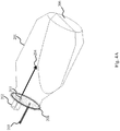
- a tilt rotary furnace 201 is charged with an aluminum charge or melt 206 including a quantity of aluminum scrap and a corresponding quantity of salt.
- the furnace 201 includes a burner 202 having a nozzle 207 positioned on a door 208.
- the burner 202 is configured to inject a flow of combustion gases 204 into the furnace 201, to heat the aluminum charge or melt 206.
- the burner 202 may be fixedly attached perpendicular to the door 208, or alternatively the burner 202 may be mounted substantially parallel to the surface of the aluminum charge or melt 206 so that the flow of the combustion gases 204 is substantially parallel to the surface of the aluminum charge or melt 206.
- the burner 202 is removable from the door 208 and is instead inserted into a hole (not shown) in the door 208.
- the system further comprises a lance 203, which may be fixedly attached to the door 208 or inserted through the hole in the door 208.
- the lance 203 is configured to inject a non-oxidizing gas 205, and may similarly be mounted substantially perpendicular to the door 208 or substantially parallel to the surface of the aluminum charge or melt 206.
- the lance 203 is mounted such that the flow of the non-oxidizing gas 205 is substantially parallel to the flow of the combustion gases 204 from the burner 202.
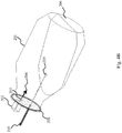
- one embodiment of the system of the present invention further comprises a gas injector 301, which may be fixedly attached to the outside of the furnace 201, to the door 208, or alternatively may be separate from the remainder of the apparatus and moved into position at the appropriate time.
- the gas injector 301 is a pipe or manifold having a plurality of nozzles or holes to distribute a non-oxidizing gas.
- the gas injector 301 may be a rake.
- the rake 301 comprises an inlet 303 and one or more outlet holes 304 positioned along the barrel, configured to inject one or more streams of non-oxidizing gas 302 into the furnace 201.
- the rake 301 is mounted such that, when the door 208 is opened, the outlet holes 304 are oriented to inject streams of the non-oxidizing gas 302 substantially parallel to the surface of the aluminum charge or melt 206.
- a melting phase of a method of the present invention is shown.
- the initial parts of the melting phase are carried out according to standard practice followed by operators, where scrap is charged with salt as normal, but thanks to the improvements of the present invention, less salt is required.
- a melt performed according to a method of the present invention requires at least 50% less salt than a conventional melt. In another embodiment, 80% less salt is required.
- the burner 207 operates at a high temperature and injects the combustion gases 204 into the tilt rotary furnace 201. In one embodiment, during the melting phase, there is little or no non-oxidizing gas flow from the non-oxidizing gas injector 203.
- a transition phase begins.
- the burner 207 is reduced to low fire or turned off.
- the non-oxidizing gas 205 is then injected via the non-oxidizing gas injector 203, where ideally two to three furnace volumes of gas should be injected over a five to ten minute period.
- the non-oxidizing gas 205 is injected from the gas injector 203 at a velocity of about 425 m/s.
- the gas injection velocity may be at least 200 m/s, at least 300 m/s, at least 400 m/s, or at least 500 m/s.
- the rate of non-oxidizing gas injection may vary by the type of scrap used, the type of non-oxidizing gas used, and the geometry of the furnace.
- the non-oxidizing gas is injected via the lance 203.
- the non-oxidizing gas 205 has a high flow velocity and the lance 203 is angled in such a way that the non-oxidizing gas flow complements that of the burner. Specifically, the lance 203 and the burner 207 are angled such that if the burner 207 remains on during the injection of the non-oxidizing gas 205, the two flows 204 and 205 will not disturb one another and the non-oxidizing gas 205 forms a blanket above the molten metal 206.
- the transition phase shown in Fig. 4B is followed by a stirring phase.
- a stirring phase of a method of the present invention is shown in Fig. 4C .
- the melt 206 is stirred by a stirring device inserted through the furnace door 208 (which is opened for that purpose) and/or by rolling or continuing to roll the furnace 201.
- stirring devices are known in the art, and include, for example, a JCB or a forklift or the like with a long attachment that is used to manually stir the molten bath.
- the non-oxidizing gas injector 203 floods the furnace 201 with non-oxidizing gas in order to protect the molten bath 206 from oxygen inside the furnace 201.
- the purpose of the stirring phase is to uniformly distribute the temperature of the bath and to break up any relatively large pieces of scrap remaining. In some embodiments, the process takes between 5 and 10 minutes and may need to be repeated. Once the first stir is completed, the door is closed again and the operator will determine whether more stirring is required. In some embodiments, if more stirring is needed, a method of the present invention may repeat the transition phase, as shown in Fig. 4B , in whole or in part.
- the non-oxidizing gas blanket formed by the non-oxidizing gas stream 205 remains on top of the molten bath 206 and acts as a shield against oxidation.
- additional non-oxidizing gas is introduced during the stirring phase across the top of the melt.
- the additional non-oxidizing gas is introduced via a rake (as shown in Fig. 4C ).
- a tapping phase of a method of the present invention is shown in Fig. 4D .
- Preparation for tapping the molten aluminum is carried out according to normal practice.
- the door 208 slides open, but in other embodiments, the door 208 may be attached to the furnace 201 using a mechanical arm configured to lift the door 208 away from the furnace 201 when desired, or using a hinge means so that the door 208 may tilt upward slightly to allow molten metal to pour out.
- the additional non-oxidizing gas injector 301 is used to introduce non-oxidizing gas across the surface of the melt 206.
- the injector 301 comprises a single, flat wide-angle spray nozzle, in another embodiment, shown in Fig.
- the injector 301 comprises several nozzles positioned along the width of the surface of the molten bath 206.
- the injector 301 comprises a rake.
- the non-oxidizing gas 302 is injected from the gas injector 301 at a velocity of 340 m/s.
- the gas injection velocity may be at least at least 50 m/s, at least 200 m/s, at least 300 m/s, or at least 400 m/s.
- the gas stream 302 introduced by the injector 301 is parallel or as close to parallel as practicable to the surface of the molten bath 206.
- One object of the non-oxidizing gas stream 302 is to prevent or inhibit oxygen molecules from coming into contact with the aluminum, which may be accomplished by providing a blanketing layer above the molten bath 206, or by dilution of oxygen-containing gases in the furnace, or by some combination thereof. Additionally, the gas stream 302 additionally and beneficially provides cooling to the molten bath 206.
- a method of the present invention involves multiple alternating stirring and pouring phases, wherein the stirring is accomplished by rolling and the gas stream 302 from the injector 301 is introduced during each pouring phase in order to minimize exposure to oxygen entering through the gap in the furnace door 208.
- Slag is a waste product of the melting process composed mainly of oxides, salt, and aluminum. Slag is deemed hazardous waste and therefore cannot be disposed of in a landfill. Reprocessing slag costs time and money, and the slag itself captures aluminum, reducing yield. Reprocessing slag is also very energy intensive, and so methods of the present invention consume less energy than conventional recycling methods. More slag forms as more salt is added, and so slag reduction constitutes a further advantage to reducing salt use in aluminum recycling.
- Slag buildup contains captured aluminum as well as impurities.
- the captured aluminum and impurities undergo various exothermic reactions that can cause a significant temperature increase during the stirring (rolling) and pouring phases of a method of the invention. Compounding the problem, lower salt content in the melt results in more efficient heat transfer.
- a method of the present invention includes a slagging stage, wherein any slag material remaining in the furnace 201 is removed by pouring, similarly to the pouring stage shown in Fig. 4 .
- slag comes into contact with air resulting in exothermic oxidation which can cause overheating as described above.
- the introduction of non-oxidizing gas during the slagging stage and the previous stages, as shown in Fig. 4 can mitigate this effect by convective cooling, since the temperature of the non-oxidizing gas is relatively colder than the temperature of the melt, as well as by blanketing or inerting the atmosphere above the melt.
- a stratified atmosphere is formed in an aluminum furnace, the stratified atmosphere having at least one non-oxidizing layer interposed between the combustion zone and the aluminum charge to separate the combustion zone from the aluminum, and to thereby inhibit oxidation of the aluminum.
- this stratified atmosphere may employ a single non-oxidizing layer or more than one non-oxidizing layer.
- the main benefit of employing stratified atmosphere protection is to significantly reduce the amount of salt required to protect the aluminum.
- One tradeoff is that overall furnace efficiency may be reduced slightly, due to the additional heat load of cold non-oxidizing gas added to the furnace. Additional benefits may be realized, for example improving aluminum quality and yield.
- One of the main purposes of adding salt into the melt is to protect the aluminum from oxidation. If the stratified atmosphere protection method is employed correctly, it is possible to significantly reduce the amount of salt required in the process. If less oxygen comes into contact with the melt, there will be less oxidation, resulting in a better yield.
- Embodiments of the present invention can be operated to form one gaseous zone, two gaseous zones as in Fig. 1 or more than two gaseous zones.
- the burner 207 combusts oxidant and fuel to create heat for melting the aluminum charge 206 positioned in the bottom of the furnace 201.
- the combusting oxidant and fuel creates a combustion zone or layer in the furnace space above the aluminum charge. Because the primary heat transfer mechanism to the aluminum charge 206 is by radiation rather than by convection, creating a stratified atmosphere will not significantly diminish heating of the aluminum.
- the oxidant in the burner may be an oxygen-enriched air, rather than air, having a molecular oxygen concentration of at least 23%, at least 30%, at least 70%, at least 90%, or at least 95%. Any standard burner can be used in this embodiment.
- burner is high velocity burner, meaning that at least one of the oxidant and fuel is introduced into the furnace at a velocity of at least 60 feet per second, preferably at least 75 feet per second, and more preferably at least 100 feet per second.
- This high velocity allows the flame to penetrate the furnace sufficiently before circulating back toward the flue, which in a typical aluminum rotary furnace is located in the door above the location of the burner.
- the flue could be positioned at the back of the furnace, opposite the burner.
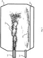
- a non-oxidizing gas is introduced by an injector, nozzle, or lance 503, below a burner 502, to form a protective non-oxidizing zone or layer 506 below a combustion layer 505 emitted from the burner 502.
- the non-oxidizing gas is introduced near an aluminum charge or melt 504 to create a blanket or shield that further reduces the amount of oxidizer coming into contact with the aluminum 504.
- the non-oxidizing gas may be any gas that is not substantially involved in hydrocarbon combustion or oxidation, for example nitrogen or argon.
- the present invention further includes a method of reducing salt use in an aluminum melt.
- a method of the present invention comprises a melting phase 900, comprising the steps of introducing fuel and oxidant flows into a furnace containing a charge 901, with the fuel and oxidant reacting to form a combustion zone above the charge 902.
- the method of the present invention commences a transition phase 910, comprising the steps of reducing the firing rate of the burner 911, introducing a non-oxidizing gas flow into the furnace at a first velocity to form a non-oxidizing zone between the combustion zone and the aluminum charge 912, and allowing the aluminum charge to become completely molten 914.
- a method of the present invention comprises one or more optional stirring phases 920.
- the non-oxidizing gas flow is halted 921, the charge is stirred 922, and then the flow of non-oxidizing gas resumes at the same or a different flow rate 923.
- methods of the present invention comprise multiple alternating stirring and transition phases. When the aluminum charge has become completely molten, the method of the present invention commences a tapping phase 930, wherein the molten aluminum charge is poured out of the furnace 931.
- exhaust gas recirculation may be used to add heat to the non-oxidizing gas, either by heat exchange or by blending or mixing in.
- exhaust gas recirculation can be used to provide the non-oxidizing layer itself.
- the addition of more water may result in excessive hydrogen absorption into the melt and may not be desirable.
- Optimum amounts of exhaust gas recirculation or preheating of the non-oxidizing flow may be determined experimentally.
- an initial flow rate of nitrogen or argon would be required to form a non-oxidizing gas blanket, followed by a maintenance flow rate (which may be the same or lower than the initial flow rate) to ensure that the non-oxidizing gas blanket remains sufficiently intact to cover the melt, or at least to significant dilute by mixing any oxidant that gets near the melt.
- An expected initial nitrogen flow rate would be from 50 to 400 normal meters cubed per hour (Nm 3 /hr) and preferably from 50 to 200 Nm 3 /hr, for an initial period of time, to cover the melt.
- the initial period of time may be at least 1 minute and less than 60 minutes, and is preferably about 5 to 30 minutes.
- An expected maintenance flow rate would be from 1 to 300 Nm 3 /hr (5% to 75% of the initial flow rate), preferably 10 to 200 Nm 3 /hr (20% to 50% of the initial flow rate), and more preferably 10 to 100 Nm 3 /hr (20% to 25% of the initial flow rate) for at least a portion of the remainder of the melt cycle.
- the melting of scrap aluminum often includes an early stage where contaminants such as paints, coatings, and other organic or volatile materials are burned off, oxidized, or vaporized from the scrap, followed by a melting stage in which the remaining aluminum metal is melted. Therefore, during the early stage, it is necessary and desirable to have an oxygen-containing atmosphere in contact with the aluminum charge, such that the system and method described herein would be operated only after such contaminants have been removed. Also, as noted above, solid aluminum scrap has a thin oxide layer protecting it from further oxidation, so that the stratified atmosphere is not necessary until break-down of that oxide layer begins. Systems and methods related to the initial stage in which contaminants are removed are described, for example, in US 9091484 .
- the method described herein for creating a stratified atmosphere will be applied at a later stage of the melt, when the aluminum is either almost melted or has started melting. Prior to this, the solid aluminum already has a protective aluminum oxide layer and therefore additional protection is not required.
- the main purpose of the stratified atmosphere is to replace the salt in protecting the aluminum from oxidation during the melting process.
- salt benefits the process more than simply protecting the aluminum from oxidation
- use of the stratified atmosphere system may need to be adjusted depending on the different types of scrap charged. For example, different materials may require different burner firing rates, different non-oxidizing gas velocities, or different non-oxidizing gas flow rates. In most cases, at least a percentage of the salt can be replaced with a stratified atmosphere for protection.
- Table 1 Test Scrap Weight Reference Salt Usage Salt Used Salt Saved Melt 1 7078 kg 630 kg 250 kg/40% 380 kg/60% Melt 2 6465 kg 600 kg 240 kg/40% 380 kg/60% Melt 3 6891 kg 630 kg 130 kg/20% 500 kg/80%
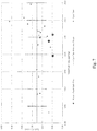
- Fig. 6 shows the specific gas and specific oxygen performance metrics.
- the blue data points show the spread of the reference data and the blue lines with error bars show the averaged (mean) value for normal operation.
- the average specific gas is 34.8 Nm 3 /MT of the total scrap charged.
- the standard deviation was calculated as 3.5 Nm 3 /MT, which is 10.0% of the mean and is represented by the blue error bars.
- the specific gas used during the nitrogen injection experiments should therefore, fall within the range of 31.3 - 38.3 Nm 3 /MT, matching the performance of a normal melt. Large red triangles represent specific gas and it can be seen that all melts fall within this range at 37.2, 36.2 and 32.7 Nm 3 /MT. This indicates that the non-oxidizing gas injection method does not significantly affect the amount of gas used to complete a melt.
- Fig. 6 also shows specific oxygen.
- the data suggests the same observations are true for oxygen usage as described above for gas usage.
- the average specific oxygen is 64.1 Nm 3 /MT of the total scrap charged.
- the standard deviation was calculated as 6.1 Nm 3 /MT, which is 9.6% of the mean, represented by the blue error bars.
- the specific oxygen used during the nitrogen injection experiments should therefore, fall within the range of 58.0 - 70.2 Nm 3 /MT to match the performance of a normal melt. Large green squares represent specific oxygen and again, it can be seen that all melts fall within this range at 68.9, 67.3 and 60.6 Nm 3 /MT.
- Fig. 7 shows cycle time, which is recorded from when charging begins to when slagging ends.
- the blue data points show the spread of the reference data and the blue line with error bars show the averaged (mean) value for normal operation.
- the average cycle time is 3.26 hours (or 03:15:36 in hr:min:sec).
- the standard deviation was calculated as 0.46 hr (27.6 mins) and therefore the normal cycle range falls within 2.80 - 3.72 hr.
- Large orange circles represent the nitrogen injection data and it can be seen that the cycle time for all three melts is somewhat lower than the normal range of operation, where the cycle time for melts 1 - 3 are 2.48, 2.48 and 2.68 hr respectively.
- Fig. 8 shows melt rate, which was determined from the charge weight and cycle time.
- the average melt rate can be seen as 2.10 MT/hr, taken across the entire cycle time.
- the standard deviation was calculated as 0.29 MT/hr and therefore the normal operational range is 1.81 - 2.39 MT/hr.
- the melt rate for melts 1 - 3 was 2.85, 2.61 and 2.58 respectively.
- the melt rate is significantly improved when less salt is used, which is in line with expectations.
- Salt mets use a relatively low amount of salt (100kg/MT of salt mets charged), compared with other materials, such as mets and dross, which use 130 and 160 kg/MT charged respectively.
- the potential benefit per melt is significantly higher for those materials
Landscapes
- Engineering & Computer Science (AREA)
- Mechanical Engineering (AREA)
- Chemical & Material Sciences (AREA)
- General Engineering & Computer Science (AREA)
- Manufacturing & Machinery (AREA)
- Materials Engineering (AREA)
- Metallurgy (AREA)
- Organic Chemistry (AREA)
- Manufacture And Refinement Of Metals (AREA)
Claims (17)
- Verfahren zum Schmelzen von einer Aluminiumbeschickung, die nicht mehr als 4 % Salz auf Massebasis umfasst, in einem Ofen, wobei das Verfahren das folgende umfasst:während einer Schmelzphase, Einführen von Brennstoff und Oxidationsmittel über einen Brenner, der mit einer ersten Feuerungsrate arbeitet, in den Ofen, wobei der Brennstoff und das Oxidationsmittel reagieren, um über der Aluminiumbeschickung eine Verbrennungszone zu bilden;Beenden von der Schmelzphase und Beginnen von einer Übergangsphase, wenn die Aluminiumbeschickung fast vollständig geschmolzen ist;während der Übergangsphase:Reduzieren von der Feuerungsrate des Brenners auf eine zweite Feuerungsrate, die niedriger als die erste Feuerungsrate ist,Einführen von einem nichtoxidierenden Gas in den Ofen mit einer ersten Geschwindigkeit, um eine nichtoxidierende Zone zwischen der Verbrennungszone und der Aluminiumbeschickung zu bilden; undErmöglichen, dass die Aluminiumbeschickung vollständig schmilzt; undBeenden von der Übergangsphase und Beginnen von einer Entnahmephase zu einem Zeitpunkt, nachdem die Aluminiumbeschickung vollständig geschmolzen ist; undwährend der Entnahmephase, Gießen von der geschmolzenen Aluminiumbeschickung aus dem Ofen.
- Verfahren nach Anspruch 1, ferner umfassend die folgenden Schritte:
nach der Übergangsphase und vor der Entnahmephase, Beginnen von einer Rührphase, die die folgenden Schritte umfasst:Anhalten von dem Strom des nichtoxidierendem Gas;Rühren von der geschmolzenen Aluminiumbeschickung; undWiederaufnehmen von dem Strom des nichtoxidierendem Gases mit einer zweiten Geschwindigkeit. - Verfahren nach Anspruch 1 oder 2, wobei die geschmolzene Aluminiumbeschickung von einem oder beiden von einem Gerät gerührt wird, das an einem baumaschinenartigen Fahrzeug befestigt ist und den Ofen um eine Achse rollt.
- Verfahren nach einem der Ansprüche 1 bis 3, ferner umfassend, während der Entnahmephase, Strömen von dem nichtoxidierenden Gas mit einer dritten Geschwindigkeit über die geschmolzene Aluminiumbeschickung, während die geschmolzene Aluminiumbeschickung aus dem Ofen gegossen wird.
- Verfahren nach einem der Ansprüche 1 bis 4, wobei das nichtoxidierende Gas ein inertes Gas ist und wobei die nichtoxidierende Zone eine inerte Zone ist.
- Verfahren nach einem der Ansprüche 1 bis 5, wobei der Strom des nichtoxidierenden Gases unter einem Winkel eingeführt wird, der komplementär zu einem Winkel von dem Strom von Brennstoff und Oxidationsmittel ist, so dass der Strom des nichtoxidierenden Gases und der Strom des Brennstoffs und des Oxidationsmittels einander nicht wesentlich stören.
- Verfahren nach Anspruch 6, wobei der Strom des nichtoxidierenden Gases eine Decke über dem geschmolzenen Aluminium bildet.
- Verfahren nach einem der Ansprüche 1 bis 7, wobei die erste Geschwindigkeit des nichtoxidierenden Gasstroms mindestens 400 m/s beträgt.
- Verfahren nach einem der Ansprüche 2 bis 8, wobei die zweite Geschwindigkeit des nichtoxidierenden Gasstroms gleich oder kleiner als die erste Geschwindigkeit ist.
- Verfahren nach einem der Ansprüche 4 bis 9, wobei die dritte Geschwindigkeit des nichtoxidierenden Gasstroms gleich oder kleiner als die erste Geschwindigkeit ist und mindestens 200 m/s beträgt.
- Verfahren nach einem der Ansprüche 4 bis 10, ferner umfassend, während der Entnahmephase, das folgende:Kühlen von dem Strom des nichtoxidierenden Gases; undkonvektives Kühlen von dem geschmolzenen Aluminium mit dem Strom des nichtoxidierendem Gases.
- System zum Schmelzen von einer Aluminiumbeschickung, die nicht mehr als 4% Salz auf Massebasis umfasst, in einem Dreh-Kipp-Ofen, der eine Tür aufweist, umfassend:einen Brenner, der in der Tür des Ofens angebracht ist, wobei der Brenner so konfiguriert ist, dass er Brennstoff und Oxidationsmittel in den Ofen einführt, um eine Verbrennungszone über der Aluminiumbeschickung zu bilden;eine Lanze, die so konfiguriert ist, dass sie ein nichtoxidierendes Gas in den Ofen einführt, um eine nichtoxidierende Zone zwischen der Verbrennungszone und der Aluminiumbeschickung zu bilden; undeinen Gasinjektor, der so konfiguriert ist, dass er ein nichtoxidierendes Gas in der Nähe von der Tür des Ofens einführt.
- System von Anspruch 12, wobei die Lanze an der Tür des Ofens angebracht ist.
- System nach Anspruch 13, wobei die Lanze so konfiguriert ist, dass sie nichtoxidierendes Gas mit einer Geschwindigkeit von mindestens 400 m/s einführt.
- System nach einem der Ansprüche 12 bis 14, wobei der Gasinjektor einen Verteiler umfasst, der einen oder mehrere Auslässe umfasst, wobei der eine oder die mehreren Auslässe so konfiguriert sind, dass sie bei geöffneter Tür einen planaren Strom von nichtoxidierendem Gas in den Ofen liefern.
- System nach einem der Ansprüche 12 bis 15, wobei der Gasinjektor so konfiguriert ist, dass er das nichtoxidierende Gas mit einer Geschwindigkeit von mindestens 200 m/s liefert.
- System nach einem der Ansprüche 12 bis 16, wobei der Gasinjektor so ausgerichtet ist, dass die Auslässe den Strom des nichtoxidierenden Gases im Wesentlichen parallel zu einer oberen Oberfläche der Aluminiumbeschickung einführen.
Priority Applications (1)
| Application Number | Priority Date | Filing Date | Title |
|---|---|---|---|
| PL18211465T PL3499162T3 (pl) | 2017-12-18 | 2018-12-11 | Sposób ograniczenia zużycia soli w recyklingu aluminium |
Applications Claiming Priority (1)
| Application Number | Priority Date | Filing Date | Title |
|---|---|---|---|
| US15/845,113 US10669609B2 (en) | 2017-12-18 | 2017-12-18 | Method for reducing salt usage in aluminum recycling |
Publications (2)
| Publication Number | Publication Date |
|---|---|
| EP3499162A1 EP3499162A1 (de) | 2019-06-19 |
| EP3499162B1 true EP3499162B1 (de) | 2020-06-17 |
Family
ID=64664609
Family Applications (1)
| Application Number | Title | Priority Date | Filing Date |
|---|---|---|---|
| EP18211465.2A Active EP3499162B1 (de) | 2017-12-18 | 2018-12-11 | Verfahren zur reduzierung des salzverbrauchs beim aluminiumrecycling |
Country Status (12)
| Country | Link |
|---|---|
| US (1) | US10669609B2 (de) |
| EP (1) | EP3499162B1 (de) |
| KR (1) | KR102254059B1 (de) |
| CN (1) | CN110006253B (de) |
| AR (1) | AR113955A1 (de) |
| BR (1) | BR102018075809B1 (de) |
| CA (1) | CA3027093C (de) |
| CO (1) | CO2018013406A1 (de) |
| ES (1) | ES2806548T3 (de) |
| MX (1) | MX395653B (de) |
| PL (1) | PL3499162T3 (de) |
| TW (1) | TWI701341B (de) |
Families Citing this family (2)
| Publication number | Priority date | Publication date | Assignee | Title |
|---|---|---|---|---|
| CN120304077B (zh) * | 2025-05-13 | 2025-10-21 | 大唐同舟科技有限公司 | 一种基于粉煤灰修复盐碱地的混合装置及其修复方法 |
| CN121046651B (zh) * | 2025-11-04 | 2026-02-27 | 赛恩斯环保股份有限公司 | 一种电解铝灰中的铝的回收方法 |
Family Cites Families (12)
| Publication number | Priority date | Publication date | Assignee | Title |
|---|---|---|---|---|
| US4983216A (en) | 1990-02-12 | 1991-01-08 | Aluminum Company Of America | Aluminum scrap melting |
| AT400448B (de) * | 1993-10-01 | 1995-12-27 | Kos Bernd Dipl Ing Dr | Verfahren und vorrichtung zur aufbereitung von mischungen aus leichtmetall |
| US5563903A (en) | 1995-06-13 | 1996-10-08 | Praxair Technology, Inc. | Aluminum melting with reduced dross formation |
| US5961689A (en) | 1998-03-03 | 1999-10-05 | Praxair Technology, Inc. | Method of protective atmosphere heating |
| DE19824573A1 (de) | 1998-06-02 | 1999-12-09 | Linde Ag | Verfahren zum Schmelzen von Metallen |
| AT409269B (de) * | 2000-09-08 | 2002-07-25 | Heribert Dipl Ing Dr Summer | Verfahren zum salzlosen und oxidationsfreien umschmelzen von aluminium |
| CN102803163B (zh) | 2009-06-12 | 2015-11-25 | 气体产品与化学公司 | 用于控制熔融材料氧化状态的熔炉和方法 |
| CN201704386U (zh) * | 2010-04-23 | 2011-01-12 | 福州麦特新高温材料有限公司 | 一种具有密封装置的铝液在线除气机 |
| US8915733B2 (en) * | 2010-11-11 | 2014-12-23 | Air Products And Chemicals, Inc. | Selective adjustment of heat flux for increased uniformity of heating a charge material in a tilt rotary furnace |
| DE202011004762U1 (de) | 2011-04-04 | 2011-09-07 | Igus Gmbh | Energieführungskette |
| PL2664884T3 (pl) | 2012-05-18 | 2020-02-28 | Air Products And Chemicals, Inc. | Sposób i urządzenie do podgrzewania metali |
| US9689612B2 (en) * | 2015-05-26 | 2017-06-27 | Air Products And Chemicals, Inc. | Selective oxy-fuel burner and method for a rotary furnace |
-
2017
- 2017-12-18 US US15/845,113 patent/US10669609B2/en active Active
-
2018
- 2018-12-11 ES ES18211465T patent/ES2806548T3/es active Active
- 2018-12-11 EP EP18211465.2A patent/EP3499162B1/de active Active
- 2018-12-11 PL PL18211465T patent/PL3499162T3/pl unknown
- 2018-12-11 MX MX2018015457A patent/MX395653B/es unknown
- 2018-12-11 CA CA3027093A patent/CA3027093C/en active Active
- 2018-12-12 TW TW107144719A patent/TWI701341B/zh active
- 2018-12-12 CO CONC2018/0013406A patent/CO2018013406A1/es unknown
- 2018-12-12 KR KR1020180160059A patent/KR102254059B1/ko active Active
- 2018-12-12 BR BR102018075809-8A patent/BR102018075809B1/pt active IP Right Grant
- 2018-12-17 AR ARP180103678A patent/AR113955A1/es active IP Right Grant
- 2018-12-18 CN CN201811551956.5A patent/CN110006253B/zh active Active
Non-Patent Citations (1)
| Title |
|---|
| None * |
Also Published As
| Publication number | Publication date |
|---|---|
| CN110006253A (zh) | 2019-07-12 |
| US10669609B2 (en) | 2020-06-02 |
| US20190185962A1 (en) | 2019-06-20 |
| CN110006253B (zh) | 2021-03-09 |
| CO2018013406A1 (es) | 2019-12-20 |
| MX2018015457A (es) | 2019-08-29 |
| BR102018075809A2 (pt) | 2019-07-02 |
| EP3499162A1 (de) | 2019-06-19 |
| AR113955A1 (es) | 2020-07-01 |
| ES2806548T3 (es) | 2021-02-18 |
| CA3027093A1 (en) | 2019-06-18 |
| KR20190073280A (ko) | 2019-06-26 |
| CA3027093C (en) | 2021-01-12 |
| TW201928070A (zh) | 2019-07-16 |
| KR102254059B1 (ko) | 2021-05-20 |
| MX395653B (es) | 2025-03-25 |
| BR102018075809B1 (pt) | 2023-02-07 |
| TWI701341B (zh) | 2020-08-11 |
| PL3499162T3 (pl) | 2020-11-16 |
Similar Documents
| Publication | Publication Date | Title |
|---|---|---|
| CN101983087B (zh) | 处理废物的方法和设备 | |
| KR0141468B1 (ko) | 루프에 장착된 보조 산소-연소버너 | |
| US9677814B2 (en) | Continuous feeding system to a smelting furnace of pre-heated metal material, in continuous, potentiated and combined form | |
| EP0906249A2 (de) | Verfahren und vorrichtung zur abfallbehandlung bei hohen temperaturen | |
| BRPI0609774A2 (pt) | métodos para processar um pó de forno de aço e material contendo ferro e metais voláteis, e para operar um forno de indução a canal | |
| EP3499162B1 (de) | Verfahren zur reduzierung des salzverbrauchs beim aluminiumrecycling | |
| CN106563690A (zh) | 基于等离子弧技术的飞灰等离子熔融炉 | |
| KR101479603B1 (ko) | 희석 연소 | |
| WO2001004559A1 (fr) | Equipement et procede de fusion a l'arc pour source de fonte brute froide | |
| RU2346057C2 (ru) | Усовершенствованный способ плавки для получения железа | |
| CN117366615A (zh) | 用于使丸状装入物料熔化的氧气-燃料燃烧系统和方法 | |
| JP6654502B2 (ja) | ガラス溶融装置 | |
| EP4062117B1 (de) | Verbesserter plasmainduzierter rauchofen | |
| US8034283B2 (en) | Rotary hearth furnace and method of operating the same | |
| CN104024441B (zh) | 熔炼过程的启动 | |
| CN208566698U (zh) | 固废处理装置 | |
| JP4248767B2 (ja) | 廃棄物焼却灰の溶融方法および溶融装置 | |
| CN103596887B (zh) | 玻璃熔融炉 | |
| Pioro et al. | Advanced melting technologies with submerged combustion | |
| US7780436B2 (en) | Flex-flame burner and combustion method | |
| JP3305491B2 (ja) | 粒状物質の溶融炉装置及び溶融炉燃焼方法 | |
| KR20180081136A (ko) | 플로트 유리 제조 방법 및 설비 | |
| PL148248B1 (en) | Method of melting glass furnace charges | |
| Mills et al. | Technology and economics of oxy/fuel combustion | |
| ITMI20071584A1 (it) | Processo perfezionato per forni metallurgici e relativo apparato |
Legal Events
| Date | Code | Title | Description |
|---|---|---|---|
| PUAI | Public reference made under article 153(3) epc to a published international application that has entered the european phase |
Free format text: ORIGINAL CODE: 0009012 |
|
| STAA | Information on the status of an ep patent application or granted ep patent |
Free format text: STATUS: THE APPLICATION HAS BEEN PUBLISHED |
|
| AK | Designated contracting states |
Kind code of ref document: A1 Designated state(s): AL AT BE BG CH CY CZ DE DK EE ES FI FR GB GR HR HU IE IS IT LI LT LU LV MC MK MT NL NO PL PT RO RS SE SI SK SM TR |
|
| AX | Request for extension of the european patent |
Extension state: BA ME |
|
| STAA | Information on the status of an ep patent application or granted ep patent |
Free format text: STATUS: REQUEST FOR EXAMINATION WAS MADE |
|
| 17P | Request for examination filed |
Effective date: 20191218 |
|
| RBV | Designated contracting states (corrected) |
Designated state(s): AL AT BE BG CH CY CZ DE DK EE ES FI FR GB GR HR HU IE IS IT LI LT LU LV MC MK MT NL NO PL PT RO RS SE SI SK SM TR |
|
| GRAP | Despatch of communication of intention to grant a patent |
Free format text: ORIGINAL CODE: EPIDOSNIGR1 |
|
| STAA | Information on the status of an ep patent application or granted ep patent |
Free format text: STATUS: GRANT OF PATENT IS INTENDED |
|
| INTG | Intention to grant announced |
Effective date: 20200207 |
|
| GRAS | Grant fee paid |
Free format text: ORIGINAL CODE: EPIDOSNIGR3 |
|
| GRAA | (expected) grant |
Free format text: ORIGINAL CODE: 0009210 |
|
| STAA | Information on the status of an ep patent application or granted ep patent |
Free format text: STATUS: THE PATENT HAS BEEN GRANTED |
|
| AK | Designated contracting states |
Kind code of ref document: B1 Designated state(s): AL AT BE BG CH CY CZ DE DK EE ES FI FR GB GR HR HU IE IS IT LI LT LU LV MC MK MT NL NO PL PT RO RS SE SI SK SM TR |
|
| REG | Reference to a national code |
Ref country code: GB Ref legal event code: FG4D |
|
| REG | Reference to a national code |
Ref country code: CH Ref legal event code: EP |
|
| REG | Reference to a national code |
Ref country code: DE Ref legal event code: R096 Ref document number: 602018005396 Country of ref document: DE |
|
| REG | Reference to a national code |
Ref country code: IE Ref legal event code: FG4D |
|
| REG | Reference to a national code |
Ref country code: AT Ref legal event code: REF Ref document number: 1281808 Country of ref document: AT Kind code of ref document: T Effective date: 20200715 |
|
| PG25 | Lapsed in a contracting state [announced via postgrant information from national office to epo] |
Ref country code: FI Free format text: LAPSE BECAUSE OF FAILURE TO SUBMIT A TRANSLATION OF THE DESCRIPTION OR TO PAY THE FEE WITHIN THE PRESCRIBED TIME-LIMIT Effective date: 20200617 Ref country code: GR Free format text: LAPSE BECAUSE OF FAILURE TO SUBMIT A TRANSLATION OF THE DESCRIPTION OR TO PAY THE FEE WITHIN THE PRESCRIBED TIME-LIMIT Effective date: 20200918 Ref country code: NO Free format text: LAPSE BECAUSE OF FAILURE TO SUBMIT A TRANSLATION OF THE DESCRIPTION OR TO PAY THE FEE WITHIN THE PRESCRIBED TIME-LIMIT Effective date: 20200917 Ref country code: LT Free format text: LAPSE BECAUSE OF FAILURE TO SUBMIT A TRANSLATION OF THE DESCRIPTION OR TO PAY THE FEE WITHIN THE PRESCRIBED TIME-LIMIT Effective date: 20200617 Ref country code: SE Free format text: LAPSE BECAUSE OF FAILURE TO SUBMIT A TRANSLATION OF THE DESCRIPTION OR TO PAY THE FEE WITHIN THE PRESCRIBED TIME-LIMIT Effective date: 20200617 |
|
| REG | Reference to a national code |
Ref country code: LT Ref legal event code: MG4D |
|
| REG | Reference to a national code |
Ref country code: NL Ref legal event code: MP Effective date: 20200617 |
|
| PG25 | Lapsed in a contracting state [announced via postgrant information from national office to epo] |
Ref country code: RS Free format text: LAPSE BECAUSE OF FAILURE TO SUBMIT A TRANSLATION OF THE DESCRIPTION OR TO PAY THE FEE WITHIN THE PRESCRIBED TIME-LIMIT Effective date: 20200617 Ref country code: BG Free format text: LAPSE BECAUSE OF FAILURE TO SUBMIT A TRANSLATION OF THE DESCRIPTION OR TO PAY THE FEE WITHIN THE PRESCRIBED TIME-LIMIT Effective date: 20200917 Ref country code: LV Free format text: LAPSE BECAUSE OF FAILURE TO SUBMIT A TRANSLATION OF THE DESCRIPTION OR TO PAY THE FEE WITHIN THE PRESCRIBED TIME-LIMIT Effective date: 20200617 Ref country code: HR Free format text: LAPSE BECAUSE OF FAILURE TO SUBMIT A TRANSLATION OF THE DESCRIPTION OR TO PAY THE FEE WITHIN THE PRESCRIBED TIME-LIMIT Effective date: 20200617 |
|
| REG | Reference to a national code |
Ref country code: AT Ref legal event code: MK05 Ref document number: 1281808 Country of ref document: AT Kind code of ref document: T Effective date: 20200617 |
|
| PG25 | Lapsed in a contracting state [announced via postgrant information from national office to epo] |
Ref country code: AL Free format text: LAPSE BECAUSE OF FAILURE TO SUBMIT A TRANSLATION OF THE DESCRIPTION OR TO PAY THE FEE WITHIN THE PRESCRIBED TIME-LIMIT Effective date: 20200617 Ref country code: NL Free format text: LAPSE BECAUSE OF FAILURE TO SUBMIT A TRANSLATION OF THE DESCRIPTION OR TO PAY THE FEE WITHIN THE PRESCRIBED TIME-LIMIT Effective date: 20200617 |
|
| PG25 | Lapsed in a contracting state [announced via postgrant information from national office to epo] |
Ref country code: EE Free format text: LAPSE BECAUSE OF FAILURE TO SUBMIT A TRANSLATION OF THE DESCRIPTION OR TO PAY THE FEE WITHIN THE PRESCRIBED TIME-LIMIT Effective date: 20200617 Ref country code: AT Free format text: LAPSE BECAUSE OF FAILURE TO SUBMIT A TRANSLATION OF THE DESCRIPTION OR TO PAY THE FEE WITHIN THE PRESCRIBED TIME-LIMIT Effective date: 20200617 Ref country code: SM Free format text: LAPSE BECAUSE OF FAILURE TO SUBMIT A TRANSLATION OF THE DESCRIPTION OR TO PAY THE FEE WITHIN THE PRESCRIBED TIME-LIMIT Effective date: 20200617 Ref country code: PT Free format text: LAPSE BECAUSE OF FAILURE TO SUBMIT A TRANSLATION OF THE DESCRIPTION OR TO PAY THE FEE WITHIN THE PRESCRIBED TIME-LIMIT Effective date: 20201019 Ref country code: RO Free format text: LAPSE BECAUSE OF FAILURE TO SUBMIT A TRANSLATION OF THE DESCRIPTION OR TO PAY THE FEE WITHIN THE PRESCRIBED TIME-LIMIT Effective date: 20200617 |
|
| REG | Reference to a national code |
Ref country code: ES Ref legal event code: FG2A Ref document number: 2806548 Country of ref document: ES Kind code of ref document: T3 Effective date: 20210218 |
|
| PG25 | Lapsed in a contracting state [announced via postgrant information from national office to epo] |
Ref country code: IS Free format text: LAPSE BECAUSE OF FAILURE TO SUBMIT A TRANSLATION OF THE DESCRIPTION OR TO PAY THE FEE WITHIN THE PRESCRIBED TIME-LIMIT Effective date: 20201017 Ref country code: SK Free format text: LAPSE BECAUSE OF FAILURE TO SUBMIT A TRANSLATION OF THE DESCRIPTION OR TO PAY THE FEE WITHIN THE PRESCRIBED TIME-LIMIT Effective date: 20200617 |
|
| REG | Reference to a national code |
Ref country code: DE Ref legal event code: R097 Ref document number: 602018005396 Country of ref document: DE |
|
| PLBE | No opposition filed within time limit |
Free format text: ORIGINAL CODE: 0009261 |
|
| STAA | Information on the status of an ep patent application or granted ep patent |
Free format text: STATUS: NO OPPOSITION FILED WITHIN TIME LIMIT |
|
| PG25 | Lapsed in a contracting state [announced via postgrant information from national office to epo] |
Ref country code: DK Free format text: LAPSE BECAUSE OF FAILURE TO SUBMIT A TRANSLATION OF THE DESCRIPTION OR TO PAY THE FEE WITHIN THE PRESCRIBED TIME-LIMIT Effective date: 20200617 |
|
| 26N | No opposition filed |
Effective date: 20210318 |
|
| PG25 | Lapsed in a contracting state [announced via postgrant information from national office to epo] |
Ref country code: SI Free format text: LAPSE BECAUSE OF FAILURE TO SUBMIT A TRANSLATION OF THE DESCRIPTION OR TO PAY THE FEE WITHIN THE PRESCRIBED TIME-LIMIT Effective date: 20200617 |
|
| PG25 | Lapsed in a contracting state [announced via postgrant information from national office to epo] |
Ref country code: MC Free format text: LAPSE BECAUSE OF FAILURE TO SUBMIT A TRANSLATION OF THE DESCRIPTION OR TO PAY THE FEE WITHIN THE PRESCRIBED TIME-LIMIT Effective date: 20200617 |
|
| REG | Reference to a national code |
Ref country code: BE Ref legal event code: MM Effective date: 20201231 |
|
| PG25 | Lapsed in a contracting state [announced via postgrant information from national office to epo] |
Ref country code: LU Free format text: LAPSE BECAUSE OF NON-PAYMENT OF DUE FEES Effective date: 20201211 Ref country code: IE Free format text: LAPSE BECAUSE OF NON-PAYMENT OF DUE FEES Effective date: 20201211 |
|
| PG25 | Lapsed in a contracting state [announced via postgrant information from national office to epo] |
Ref country code: TR Free format text: LAPSE BECAUSE OF FAILURE TO SUBMIT A TRANSLATION OF THE DESCRIPTION OR TO PAY THE FEE WITHIN THE PRESCRIBED TIME-LIMIT Effective date: 20200617 Ref country code: MT Free format text: LAPSE BECAUSE OF FAILURE TO SUBMIT A TRANSLATION OF THE DESCRIPTION OR TO PAY THE FEE WITHIN THE PRESCRIBED TIME-LIMIT Effective date: 20200617 Ref country code: CY Free format text: LAPSE BECAUSE OF FAILURE TO SUBMIT A TRANSLATION OF THE DESCRIPTION OR TO PAY THE FEE WITHIN THE PRESCRIBED TIME-LIMIT Effective date: 20200617 |
|
| PG25 | Lapsed in a contracting state [announced via postgrant information from national office to epo] |
Ref country code: MK Free format text: LAPSE BECAUSE OF FAILURE TO SUBMIT A TRANSLATION OF THE DESCRIPTION OR TO PAY THE FEE WITHIN THE PRESCRIBED TIME-LIMIT Effective date: 20200617 |
|
| PG25 | Lapsed in a contracting state [announced via postgrant information from national office to epo] |
Ref country code: BE Free format text: LAPSE BECAUSE OF NON-PAYMENT OF DUE FEES Effective date: 20201231 |
|
| REG | Reference to a national code |
Ref country code: CH Ref legal event code: PL |
|
| PG25 | Lapsed in a contracting state [announced via postgrant information from national office to epo] |
Ref country code: LI Free format text: LAPSE BECAUSE OF NON-PAYMENT OF DUE FEES Effective date: 20211231 Ref country code: CH Free format text: LAPSE BECAUSE OF NON-PAYMENT OF DUE FEES Effective date: 20211231 |
|
| P01 | Opt-out of the competence of the unified patent court (upc) registered |
Effective date: 20230508 |
|
| PGFP | Annual fee paid to national office [announced via postgrant information from national office to epo] |
Ref country code: ES Payment date: 20250121 Year of fee payment: 7 |
|
| PGFP | Annual fee paid to national office [announced via postgrant information from national office to epo] |
Ref country code: PL Payment date: 20250929 Year of fee payment: 8 |
|
| PGFP | Annual fee paid to national office [announced via postgrant information from national office to epo] |
Ref country code: FR Payment date: 20250930 Year of fee payment: 8 |
|
| PGFP | Annual fee paid to national office [announced via postgrant information from national office to epo] |
Ref country code: DE Payment date: 20250930 Year of fee payment: 8 |
|
| PGFP | Annual fee paid to national office [announced via postgrant information from national office to epo] |
Ref country code: GB Payment date: 20251001 Year of fee payment: 8 |
|
| PGFP | Annual fee paid to national office [announced via postgrant information from national office to epo] |
Ref country code: IT Payment date: 20251121 Year of fee payment: 8 |
|
| PGFP | Annual fee paid to national office [announced via postgrant information from national office to epo] |
Ref country code: CZ Payment date: 20251124 Year of fee payment: 8 |