EP3499086A1 - Planetary gear speed reduction device - Google Patents
Planetary gear speed reduction device Download PDFInfo
- Publication number
- EP3499086A1 EP3499086A1 EP17839250.2A EP17839250A EP3499086A1 EP 3499086 A1 EP3499086 A1 EP 3499086A1 EP 17839250 A EP17839250 A EP 17839250A EP 3499086 A1 EP3499086 A1 EP 3499086A1
- Authority
- EP
- European Patent Office
- Prior art keywords
- front plate
- region
- stiffness
- plate
- carrier
- Prior art date
- Legal status (The legal status is an assumption and is not a legal conclusion. Google has not performed a legal analysis and makes no representation as to the accuracy of the status listed.)
- Pending
Links
Images


Classifications
-
- F—MECHANICAL ENGINEERING; LIGHTING; HEATING; WEAPONS; BLASTING
- F16—ENGINEERING ELEMENTS AND UNITS; GENERAL MEASURES FOR PRODUCING AND MAINTAINING EFFECTIVE FUNCTIONING OF MACHINES OR INSTALLATIONS; THERMAL INSULATION IN GENERAL
- F16H—GEARING
- F16H57/00—General details of gearing
- F16H57/08—General details of gearing of gearings with members having orbital motion
- F16H57/082—Planet carriers
-
- F—MECHANICAL ENGINEERING; LIGHTING; HEATING; WEAPONS; BLASTING
- F16—ENGINEERING ELEMENTS AND UNITS; GENERAL MEASURES FOR PRODUCING AND MAINTAINING EFFECTIVE FUNCTIONING OF MACHINES OR INSTALLATIONS; THERMAL INSULATION IN GENERAL
- F16H—GEARING
- F16H1/00—Toothed gearings for conveying rotary motion
- F16H1/28—Toothed gearings for conveying rotary motion with gears having orbital motion
- F16H1/2809—Toothed gearings for conveying rotary motion with gears having orbital motion with means for equalising the distribution of load on the planet-wheels
- F16H1/2827—Toothed gearings for conveying rotary motion with gears having orbital motion with means for equalising the distribution of load on the planet-wheels by allowing limited movement of the planet carrier, e.g. relative to its shaft
-
- F—MECHANICAL ENGINEERING; LIGHTING; HEATING; WEAPONS; BLASTING
- F16—ENGINEERING ELEMENTS AND UNITS; GENERAL MEASURES FOR PRODUCING AND MAINTAINING EFFECTIVE FUNCTIONING OF MACHINES OR INSTALLATIONS; THERMAL INSULATION IN GENERAL
- F16H—GEARING
- F16H1/00—Toothed gearings for conveying rotary motion
- F16H1/28—Toothed gearings for conveying rotary motion with gears having orbital motion
- F16H1/48—Special means compensating for misalignment of axes, e.g. for equalising distribution of load on the face width of the teeth
-
- F—MECHANICAL ENGINEERING; LIGHTING; HEATING; WEAPONS; BLASTING
- F05—INDEXING SCHEMES RELATING TO ENGINES OR PUMPS IN VARIOUS SUBCLASSES OF CLASSES F01-F04
- F05D—INDEXING SCHEME FOR ASPECTS RELATING TO NON-POSITIVE-DISPLACEMENT MACHINES OR ENGINES, GAS-TURBINES OR JET-PROPULSION PLANTS
- F05D2260/00—Function
- F05D2260/40—Transmission of power
- F05D2260/403—Transmission of power through the shape of the drive components
- F05D2260/4031—Transmission of power through the shape of the drive components as in toothed gearing
- F05D2260/40311—Transmission of power through the shape of the drive components as in toothed gearing of the epicyclical, planetary or differential type
Definitions
- the present invention relates to a planetary gear reduction device including a rotatable carrier.
- a planetary gear reduction device used in a driving force transmission mechanism in aircraft or the like, in some cases, planetary pins are bent due to driving torque applied to a carrier, parallelism of planetary gears with respect to a sun gear and a ring gear is reduced, and misalignment of meshing of the gears occurs.
- a front plate of the carrier which supports one end portions of the planetary pins, is provided with a hollow space to reduce stiffness of the front plate. In this way, bending deformation of the planetary pins is suppressed.
- Patent Literature 1 Japanese Laid-Open Patent Application Publication No. 2011-94714
- the planetary gear reduction device including the rotatable carrier, a centrifugal force of the planetary gears and the planetary pins is applied to the carrier.
- the stiffness of the front plate is made lower than that of a rear plate. Therefore, due to the centrifugal force, radially outward tensile deformation of the front plate occurs. For this reason, the planetary pins may be tilted (inclined) and misalignment may occur due to the centrifugal force.
- an object of the present invention is to prevent misalignment due to the torque transmitted to the carrier and misalignment due to the centrifugal force of the planetary gears and the planetary pins, in the planetary gear reduction device including the rotatable carrier.
- a planetary gear reduction device comprises a sun gear which receives a driving force as an input, the sun gear having external teeth; a plurality of planetary gears having external teeth which mesh with the sun gear; a ring gear having internal teeth which mesh with the plurality of planetary gears; a rotatable carrier including: a front plate including a plurality of front pin support surfaces supporting first end portions of a plurality of planetary pins, the planetary pins being axes of rotation of the plurality of planetary gears, a rear plate including a plurality of rear shaft support surfaces supporting second end portions of the plurality of planetary pins, and a coupling member coupling the front plate to the rear plate; and an output frame connected to the carrier to output the driving force, wherein the output frame is connected to a portion of a radially outer portion of the carrier, the portion being closer to the front plate than to the rear plate, wherein the carrier has a first region as an external force transmission path between the front pin support surfaces
- the output frame is connected to a portion of the radially outer portion of the carrier, the portion being closer to the front plate than to the rear plate.
- a torque reaction force from the output frame to the carrier which is generated at the front plate side, is more than that generated at the rear plate side.
- the stiffness with respect to the twist force of the first region and the stiffness with respect to the twist force of the second region are equal to each other. Therefore, a twist deformation generated in the carrier due to the torque transmitted to the carrier is balanced when viewed from the planetary pins, and tilting (inclination) of the planetary pins is prevented.
- the twist stiffness of the front plate and the twist stiffness of the rear plate are different from each other.
- the stiffness with respect to the radial tensile force applied to the front pin support surfaces and the stiffness with respect to the radial tensile force applied to the rear shaft support surfaces are equal to each other (equalized). This makes it possible to prevent tilting (inclination) of the planetary pins due to the centrifugal force.
- the planetary gear reduction device including the rotatable carrier it becomes possible to prevent misalignment due to the torque transmitted to the carrier and misalignment due to the centrifugal force of the planetary gears and the planetary pins.
- the front plate may include an outer portion which is radially outward of centers of the plurality of planetary pins
- the rear plate includes an outer portion which is radially outward of the centers of the plurality of planetary pins
- the outer portion of the front plate includes a flexible structure portion which makes the stiffness with respect to the twist force lower than that of the outer portion of the rear plate, and the stiffness with respect to the radial tensile force of a region of the front plate, the region being inward of the flexible structure portion, may be higher than that of a region of the rear plate, the region being radially inward of a portion of the rear plate, the portion conforming in radial position to the flexible structure portion.
- the outer portion of the front plate includes the flexible structure portion which makes the twist stiffness lower than that of the outer portion of the rear plate.
- the flexible structure portion With the flexible structure portion, the twist stiffness of the first region and the twist stiffness of the second region can be easily equalized.
- the tensile stiffness of the outer portion of the front plate is reduced because of the flexible structure portion provided at the outer portion of the front plate.
- the twist deformation can be substantially prevented by the radially outer portion of the carrier, and the misalignment due to the centrifugal force can be substantially prevented by the radially inner portion of the carrier.
- designing for prevention of the twist information and designing for prevention of the misalignment can be easily separately performed.
- At least one of a non-opening rate, a non-thin region rate, a minimum thickness, and a material stiffness, of the outer portion of the front plate may be made smaller than that of the outer portion of the rear plate, to form the flexible structure portion.
- the flexible structure portion can be easily formed in the front plate.
- a non-opening rate, a non-thin region rate, or a minimum thickness of the outer portion of the front plate may be smaller than that of the outer portion of the rear plate.
- the front plate may include an inner portion which is radially inward of centers of the plurality of planetary pins
- the rear plate includes an inner portion which is radially inward of the centers of the plurality of planetary pins
- the non-opening rate, the non-thin region rate, or the minimum thickness of the inner portion of the front plate may be larger than that of the inner portion of the rear plate.
- a region of the front plate, the region having a highest stiffness with respect to the radial tensile force, may be located radially inward of a region of the rear plate, the region having a highest stiffness with respect to the radial tensile force.
- the largest thickness portion of the plurality of regions corresponds to the region with a highest stiffness with respect to the radial tensile force.
- Each of the front plate and the rear plate may have a center opening through which a rotational axis line of the carrier passes, and the center opening of the front plate may be smaller than the center opening of the rear plate.
- the front plate may include a plate portion crossing a rotational axis line of the carrier, in a center portion of the front plate.
- the front plate is not formed with the center opening crossing the rotational axis line of the carrier, lubricating oil can be easily reserved in the inner space of the carrier. Since the front plate is not formed with the center opening, it becomes possible to efficiently improve the radial tensile force of the front plate. The reduction of the weight of the front plate can be suitably realized.
- the output frame may be connected to a portion of the coupling member, the portion being closer to the front plate
- the coupling member may include a front portion provided at a location that is closer to the front plate than to a location where the coupling member is connected to the output frame, and a rear portion provided at a location that is closer to the rear plate than to the location where the coupling member is connected to the output frame, and the front portion may be configured to make the stiffness with respect to the twist force lower than that of the rear portion.
- the stiffness of the first region and the stiffness of the second region can be easily equalized in the carrier. Since the coupling member serves to reduce the twist stiffness in the first region of the carrier, designing of the front plate can be simplified.
- the front plate and the rear plate may have the same shape.
- the front plate and the rear plate can be easily designed.
- front-rear relation is not limited to this.
- Fig. 1 is a partial cross-sectional view of a planetary gear reduction device 1 according to Embodiment 1.
- the planetary gear reduction device 1 is used as, for example a driving force transmission mechanism (speed reduction mechanism) of an aircraft engine or the like.
- the planetary gear reduction device 1 includes a sun gear 2, a plurality of planetary gears 3, a ring gear 4, a plurality of planetary pins 5, a carrier 6, and the output frame 7.
- the sun gear 2 has external teeth 2a.
- the sun gear 2 is mounted on an input shaft 8 by fitting or spline coupling so that the sun gear 2 is rotatable together with the input shaft 8.
- a rotational driving force is transmitted from an engine to the input shaft 8.
- the plurality of planetary gears 3 include external teeth 3a which mesh with the external teeth 2a of the sun gear 2.
- the plurality of planetary gears 3 are disposed to be equally spaced apart from each other (positioned at equidistant locations) around an axis line X of the sun gear 2.
- the ring gear 4 includes internal teeth 4a which mesh with the external teeth 3a of the planetary gears 3, and a fastening flange 4b. The ring gear 4 is unrotatably fastened at the flange 4b.
- each of the planetary gears 3 is constituted by double teeth rows.
- each of the planetary gears 3 may be a single teeth row, or three or more teeth rows.
- the carrier 6 includes the front plate 11, the rear plate 12, and a plurality of coupling members 13.
- the front plate 11 includes a plurality of front pin support portions 11a formed with front pin support surfaces 11aa supporting the first end portions of the plurality of planetary pins 5, respectively.
- the rear plate 12 includes a plurality of rear shaft support portions 12a formed with rear shaft support surfaces 12aa supporting the second end portions of the plurality of planetary pins 5, respectively.
- Each of the front pin support portions 11a and the rear shaft support portions 12a has a cylindrical (tubular) shape.
- the front pin support surfaces 11aa and the rear shaft support surfaces 12aa are tubular surfaces.
- each of the front pin support portions 11a and the rear shaft support portions 12a may not have the cylindrical shape and may have a, for example, tubular shape with a rectangular cross-section.
- the planetary pins 5 are inserted into the front pin support portions 11a and the rear shaft support portions 12a.
- the front pin support portions 11a and the rear shaft support portions 12a may not protrude with a tubular shape in a direction of the axis line X so long as the front pin support surfaces 11aa and the rear shaft support surfaces 12aa have a tubular shape.
- the front pin support portions 11a and the rear shaft support portions 12a may be coplanar (flush) with surfaces (e.g., surfaces of an outer portion and an inner portion (described later), facing in the direction of the axis line X) adjacent to them.
- Each of the plurality of coupling members 13 has a post shape.
- the plurality of coupling members 13 couple the radially outer end portion of the front plate 11 to the radially outer end portion of the rear plate 12.
- the plurality of coupling members 13 are arranged with gaps G (see Fig. 2 ) in the circumferential direction around the axis line X.
- the planetary gears 3 are exposed through the gaps G.
- the internal teeth 4a of the ring gear 4 mesh with the external teeth 3a of the planetary gears 3 through the gaps G each of which is between adjacent coupling members 13.
- the shape of the coupling members is not limited so long as the gaps G through which the planetary gears 3 are exposed.
- the output frame 7 is connected to the radially outer portion of the carrier 6.
- the output frame 7 is configured to output a rotational driving force from the carrier 6.
- the output frame 7 is connected to a portion of the radially outer portion of the carrier 6, the portion being closer to the front plate 11 than to the rear plate 12.
- the output frame 7 is connected to the front plate 11.
- the output frame 7 includes a tubular portion 7a protruding in the direction of the axis line X from an end surface of the outer peripheral portion of the carrier 6, the end surface being closer to the front frame 11, and a flange 7b protruding radially outward from a protruding end of the tubular portion 7a.
- the output frame 7 is integrated with the carrier 6.
- the radial position of the tubular portion 7a conforms to those of the coupling members 13.
- a driven member e.g., shaft of a fan
- the shape of the output frame 7 is not particularly limited so long as the output frame 7 is secured to the driven member so that the driving force can be transmitted to the driven member.
- the output frame 7 may be fastened to the carrier 6 by a fastening member.
- the rotational driving force from the input shaft 8 is input to the sun gear 2 in a state in which the ring gear 4 is unrotatably fastened (fixed), the planetary gears 3 rotate (rotate around their axes) around the planetary pins 5, and the carrier 6 rotates (revolves) around the axis line X of the sun gear 2.
- the carrier 6 rotates at a high speed equal to or higher than 1000rpm.
- the rotational driving force of the carrier 6 is output to the driven member via the output frame 7.
- the ring gear 4 does not rotate and the carrier 6 rotates. Therefore, a reduction gear ratio increases and the driving torque transmitted to the carrier 6 increases.
- both of the carrier and the ring gear may be rotatable. This is especially effective to the planetary gear reduction device in which a great centrifugal force is applied to the planetary gears and the planetary pins, like the planetary gear speed reducer.
- Fig. 2 is a perspective view of the planetary gears 3, the planetary pins 5, the carrier 6, and the output frame 7 of the planetary gear reduction device 1 of Fig. 1 , which are seen from the front plate 11.
- Fig. 3 is a perspective view of the planetary gears 3, the planetary pins 5, the carrier 6, and the output frame 7 of Fig. 2 , which are seen from the rear plate 12.
- the external teeth 3a of the planetary gears 3 are omitted. As shown in Figs.
- the front plate 11 includes the front pin support portions 11a, an outer portion 11b which is radially outward of the centers of the front pin support portions 11a (the centers of the planetary pins 5), and an inner portion 11c which is radially inward of the centers of the front pin support portions 11a.
- the rear plate 12 includes the rear shaft support portions 12a, an outer portion 12b which is radially outward of the centers of the rear shaft support portions 12a (the centers of the planetary pins 5), and an inner portion 12c which is radially inward of the centers of the rear shaft support portions 12a.
- a portion (external force transmission path) of the carrier 6, which is between the front pin support surfaces 11aa and the output frame 7 is defined as a first region R1.
- a portion (external force transmission path) of the carrier 6, which is between the rear shaft support surfaces 12aa and the output frame 7 is defined as a second region R2.
- a portion of the front plate 11 which is radially outward of the centers of the front pin support portions 11a forms the first region R1
- a portion of the rear plate 12 which is radially outward of the centers of the rear shaft support portions 12a and the coupling members 13, form the second region R2.
- a portion of the front plate 11, the portion being outward of a pitch circle connecting the center axes of the planetary pins 5, forms the first region R1.
- a portion of the rear plate 12, the portion being outward of the pitch circle connecting the center axes of the planetary pins 5, and the coupling members 13, form the second region R2.
- the carrier 6 has a shape in which a stiffness of the first region R1 with respect a twist force and a stiffness of the second region R2 with respect a twist force are equal to each other.
- the twist force means a force applied in a direction in which the carrier 6 is twisted around the axis line X.
- the outer portion 11b of the front plate 11 includes a flexible structure portion F which makes the stiffness with respect to the twist force lower than that of the outer portion 12b of the rear plate 12.
- the flexible structure portion F may be formed by increasing the opening rate of the outer portion 11b. Further, the flexible structure portion F may be formed by making the thickness of the outer portion 11b in the direction of the axis line X smaller than that of the inner portion 11c. In the present embodiment, the flexible structure portion F is formed by setting the opening rate of the outer portion 11b to be more than 50% and by making the thickness of the outer portion 11b in the direction of the axis line X smaller than that of the inner portion 11c.
- the flexible structure portion F is comprised of a plurality of coupling portions 11bb coupling an outer peripheral portion 11ba of the outer portion 11b, extending along the outer periphery of the carrier 6, to the front pin support portions 11a.
- the plurality of coupling portions 11bb are arranged to be spaced apart from each other in the circumferential direction.
- the plurality of coupling portions 11bb have a sector shape in which a circumferential width increases toward a radially outer (outward) side, when viewed from the direction of the axis line X.
- the stiffness with respect the twist force, of the outer portion 12b of the rear plate 12 is higher than that of the outer portion 11b of the front plate 11.
- the opening rate of the outer portion 12b of the rear plate 12 is less than that of the outer portion 11b of the front plate 11.
- the outer portion 12b of the rear plate 12 may have a minimum (smallest) thickness larger than that of the outer portion 11b of the front plate 11.
- a distance from the output frame 7 to the front pin support surfaces 11aa of the carrier 6 is shorter than a distance from the output frame 7 to the rear shaft support surfaces 12aa of the carrier 6 through the coupling members 13.
- the stiffness with respect the twist force of the outer portion 11b of the front plate 11 is lower than that of the outer portion 12b of the rear plate 12. Therefore, the stiffness of the first region R1 with respect the twist force and the stiffness of the second region R2 with respect the twist force are equal to each other.
- the front plate 11 and the rear plate 12 have shapes in which a stiffness with respect to a radial tensile force applied to the front pin support surfaces 11aa and a stiffness with respect to a radial tensile force applied to the rear shaft support surfaces 12aa are equal to each other (equalized). Specifically, the stiffness with respect to the radial tensile force, of the outer portion 11b of the front plate 11, is lower than that of the outer portion 12b of the rear plate 12.
- the stiffness with respect to the radial tensile force of a region of the front plate 11, the region being radially inward of the flexible structure portion F, is higher than that of a region of the rear plate 12, the region being radially inward of a portion of the rear plate 12, the portion conforming in radial position to the flexible structure portion F.
- the inner portion 11c of the front plate 11 has a star shape coupling the front pin support portions 11a to each other at locations that are radially inward of the front pin support portions 11a.
- the inner portion 11c has a center opening S1 through which the axis line X passes.
- the inner portion 11c has a shape in which arms radially extend from a center member (e.g., ring member) formed continuously in the circumferential direction around the axis line X toward the front pin support portions 11a.
- the stiffness with respect to the radial tensile force, of the inner portion 11c of the front plate 11, is higher than that of the outer portion 11b of the front plate 11.
- the inner portion 12c of the rear plate 12 linearly couples the rear shaft support portions 12a, at locations where the radial position of the inner portion 12c overlaps with those of the radially inner portions of the rear shaft support surfaces 12a.
- the inner portion 12c has a center opening S2 through which the axis line X passes.
- a region having a highest stiffness with respect to the radial tensile force, of the front plate 11, is located radially inward of a region having a highest stiffness with respect to the radial tensile force, of the rear plate 12.
- a region having a highest stiffness with respect to the radial tensile force, of a region coupling the front pin support portions 11a to each other, in the front plate 11, is located radially inward of a region having a highest stiffness with respect to the radial tensile force, of a region coupling the rear shaft support portions 12a to each other, in the rear plate 12.
- the inner portion 12c of the rear plate 12 has a thickness in the direction of the axis line X which is equal to that of the inner portion 11c of the front plate 11.
- the center opening S1 of the front plate 11 is smaller than the center opening S2 of the rear plate 12, when viewed in the direction of the axis line X.
- An opening rate of the inner portion 11c of the front plate 11 is less than that of the inner portion 12c of the rear plate 12.
- the inner portion 11c of the front plate 11, may have a minimum (smallest) thickness larger than that of the inner portion 12c of the rear plate 12. Further, the inner portion 11c of the front plate 11, may have a minimum (smallest) thickness and a non-opening rate which are less than those of the inner portion 12c of the rear plate 12.
- the stiffness with respect the twist force of the outer portion 11b of the front plate 11 is lower than that of the outer portion 12b of the rear plate 12, whereas the stiffness with respect to the radial tensile force, of the inner portion 11c of the front plate 11, is higher than that of the inner portion 12c of the rear plate 12. Therefore, the carrier 6 can be configured so that the stiffness with respect to the radial tensile force applied to the front pin support surfaces 11aa of the front plate 11 and the stiffness with respect to the radial tensile force applied to the rear shaft support surfaces 12aa of the rear plate 12 are equal to each other.
- the output frame 7 is connected to a portion of the radially outer portion of the carrier 6, the portion being closer to the front plate 11 than to the rear plate 12. Therefore, in a case where no measures are taken, a torque reaction force from the output frame 7 to the carrier 6, which is generated at the front plate 11 side is more than that generated at the rear plate 12 side.
- the stiffness of the first region R1 with respect the twist force and the stiffness of the second region R2 with respect the twist force are equal to each other. Therefore, a twist deformation generated in the carrier 6 due to the torque transmitted to the carrier 6 is balanced when viewed from the planetary pins 5, and tilting (inclination) of the planetary pins 5 is prevented.
- the twist stiffness of the front plate 11 and the twist stiffness of the rear plate 12 are different from each other.
- the stiffness with respect to the radial tensile force applied to the front pin support surfaces 11aa and the stiffness with respect to the radial tensile force applied to the rear shaft support surfaces 12aa are equal to each other. This makes it possible to prevent tilting (inclination) of the planetary pins 5 due to the centrifugal force.
- the stiffness of the first region R1 with respect the twist force and the stiffness of the second region R2 with respect the twist force are equalized in the carrier 6, and the stiffness with respect to the radial tensile force applied to the front pin support surfaces 11aa and the stiffness with respect to the radial tensile force applied to the rear shaft support surfaces 12aa are equal to each other.
- the outer portion 11b of the front plate 11 includes the flexible structure portion F which makes the twist stiffness lower than that of the outer portion 12b of the rear plate 12.
- the flexible structure portion F With the flexible structure portion F, the twist stiffness of the first region R1 and the twist stiffness of the second region R2 can be easily equalized.
- the stiffness with respect to the radial tensile force of the outer portion 11b of the front plate 11 is reduced because of the flexible structure portion F provided at the outer portion 11b of the front plate 11.
- the opening rate of the outer portion 11b of the front plate 11 is set to be larger than that of the outer portion 12b of the rear plate 12.
- the thickness of the outer portion 11b of the front plate 11 is set to be smaller than that of the outer portion 12b of the rear plate 12. This allows the front plate 11 to be easily formed with the flexible structure portion F.
- the opening rate of the outer portion 11b of the front plate 11 is set to be larger than that of the outer portion 12b of the rear plate 12.
- the opening rate of the inner portion 12c of the rear plate 12 is set to be smaller than that of the inner portion 11c of the front plate 11. This makes it possible to suitably realize reduction of the weight of the carrier 6 and equalization of the stiffness of the front plate 11 and the stiffness of the rear plate 12.
- the twist stiffness of the first region R1 of the front plate 11 is reduced so that the twist stiffness of the first region R1 and the twist stiffness of the second region R2 become equal to each other, and hence the stiffness with respect to the radial tensile force of the first region R1 of the front plate 11 is reduced.
- the center opening S1 of the front plate 11 is smaller than the center opening S2 of the rear plate 12, the stiffness with respect to the radial tensile force of the front plate 11 is easily increased. In this way, designing and manufacturing can be made easier.
- Figs. 4 to 19 show variations of the front plate of the carrier which can realize equalization of the stiffness with respect to the twist force and equalization of the stiffness with respect to the radial tensile force.
- the shapes of Modified Examples are applicable to the rear plate so long as the carrier can realize equalization of the stiffness with respect to the twist force and equalization of the stiffness with respect to the radial tensile force. In that case, the shape of the front plate and the shape of the rear plate may be different from each other.
- the same constituents as those of Embodiment 1 will not be described in repetition.
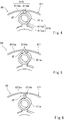
- a front plate A11 of a carrier 6A according to Modified Example 1 includes front pin support portions A11a, an outer portion A11b which is radially outward of the centers of the front pin support portions A11a (the centers of the planetary pins), and an inner portion A11c which is radially inward of the centers of the front pin support portions A11a.
- the outer portion A11b includes a flexible structure portion AF which makes a stiffness with respect to a twist force lower than that of the outer portion of the rear plate (not shown).
- the flexible structure portion AF is comprised of an outer coupling portion A11bb coupling an outer peripheral portion A11ba extending along the outer periphery of the carrier A6, of the outer portion A11b, to each of the front pin support portions A11a.
- the inner portion A11c includes an annular portion A11ca extending in the circumferential direction at a location that is radially inward of the front pin support portions A11a, and inner coupling portions A11cb coupling the front pin support portions A11a to the annular portion A11ca.
- the outer coupling portion A11bb When viewed in the direction of the axis line, the outer coupling portion A11bb has a width smaller than that of the inner coupling portion A11cb.
- the outer coupling portions A11bb has a thickness in the direction of the axis line which is smaller than that of the inner coupling portion A11cb.
- the flexible structure portion AF is formed by performing setting so that the non-opening rate and minimum (smallest) thickness of the outer portion A11b of the front plate A11 are less than those of the outer portion of the rear plate (not shown).
- the other constituents are the same as those of Embodiment 1 and will not be described in repetition.
- a flexible structure portion BF is comprised of a pair of outer coupling portions B11bb coupling each of front pin support portions B11a to an outer peripheral portion B11ba.
- a clearance (gap) is formed between the pair of outer coupling portions B11bb.
- the outer coupling portions B11bb are different from those of Modified Example 1.
- one outer coupling portion may be provided with a hole or a depressed (recessed) portion, or one coupling portion may have a hollow space.
- a flexible structure portion CF is comprised of an outer coupling portion C11bb coupling each of front pin support portions C11a to an outer peripheral portion C11ba, and the outer coupling portion C11bb has a curved shape with a flexion point.
- the outer coupling portion C11bb is different from that of Modified Example 1.
- a flexible structure portion DF is comprised of an outer coupling portion D11bb coupling each of front pin support portions D11a to an outer peripheral portion D11ba, and the outer coupling portion D11bb includes a joint portion.
- a first plate Da integrated with each of the front pin support portions D11a and protruding radially outward, and a second plate Db integrated with the outer peripheral portion D11ba and protruding radially inward are lapped to each other and fastened to each other by use of a fastening member B1 (e.g., bolt or rivet).
- a fastening member B1 e.g., bolt or rivet
- the outer coupling portion D11bb is different from that of Modified Example 1.
- the first plate Da and the second plate Db may be made of different materials (e.g., materials which are different in stiffness).
- the joint portion is not limited to fastening and may be welding. In the present Modified Example, the stiffness with respect to the twist force can be adjusted by changing the fastening structure.
- a flexible structure portion EF is comprised of an outer coupling portion E11bb coupling each of front pin support portions E11a to an outer peripheral portion E11ba.
- the outer coupling portion E11bb is made of a material with a stiffness lower than that of the material of the front pin support portions E11a.
- the outer coupling portion E11bb is secured to each of the front pin support portions E11a by welding.
- the flexible structure portion EF is formed by performing setting so that the non-opening rate and material stiffness of an outer portion E11b of the front plate E11 are lower than those of the outer portion of the rear plate (not shown).
- the outer coupling portion E11bb is different from that of Modified Example 1.
- a flexible structure portion FF has a configuration in which a gap G is formed between each of front pin support portions F11a and an outer peripheral portion F11ba, and the front pin support portion F11a and the outer peripheral portion F11ba are not directly coupled to each other.
- the outer peripheral portion F11ba and an inner portion F11c are coupled to each other by coupling portions F11d at locations which are spaced apart from the front pin support portion F11a in the circumferential direction.
- an external force transmission path between the front pin support portions F11a and the output frame 7 includes the inner portion F11c and the coupling portions F11d.
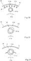
- a front plate G11 of a carrier G6 according to Modified Example 7 includes front pin support portions G11a, an outer portion G11b which is radially outward of the centers of the front pin support portions G11a, and an inner portion G11c which is radially inward of the centers of the front pin support portions G11a.
- the outer portion G11b and the inner portion G11c form a continuous annular plate.
- the outer portion G11b includes a flexible structure portion GF which makes the stiffness with respect to the twist force lower than that of the outer portion of the rear plate (not shown).
- the flexible structure portion GF has a configuration in which a plurality of holes G11ba are provided in the outer portion G11b at locations that are radially outward of the front pin support portions G11a.
- the flexible structure portion GF is formed by making the non-opening rate of the outer portion G11b of the front plate G11 less than that of the outer portion of the rear plate (not shown).
- the holes G11ba are provided over the entire outer periphery of the front plate G11.
- the shape of the holes G11ba is a rectangle, the holes G11ba may have other shapes (e.g., circle, triangle, or polygon).
- the holes G11ba may be depressed (recessed) portions which do not penetrate the outer portion G11b.
- a front plate H11 of a carrier H6 according to Modified Example 8 has a configuration in which an outer portion H11b which is radially outward of the centers of front pin support portions H11a and an inner portion H11c which is radially inward of the centers of the front pin support portions H11a form a continuous annular plate.
- the outer portion H11b and the inner portion H11c have a thickness is gradually reduced in a radially outward direction as a whole. Note that the thickness may be reduced at a constant or inconstant rate.
- the front plate H11 may have any configuration so long as the thickness is changed to form a flexible structure portion HF. It is not necessary to continuously reduce the thickness in the radially outward direction.
- the flexible structure portion HF is formed by making the minimum (smallest) thickness of the outer portion H11b of the front plate H11 less than that of the outer portion of the rear plate (not shown).
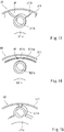
- a front plate I11 of a carrier I6 has a configuration in which an outer portion I11b which is radially outward of the centers of front pin support portions I11a and an inner portion I11c which is radially inward of the centers of the front pin support portions I11a form a continuous annular plate, and the outer portion 111b has a thickness smaller than that of the inner portion 111c.
- a flexible structure portion IF is formed by making the minimum (smallest) thickness of the outer portion I11b of the front plate I11 less than that of the outer portion of the rear plate (not shown).
- the outer portion I11b may be made of a material with a stiffness lower than that of the inner portion I11c. In that case, when a difference in Young's modulus between the materials is large, the flexible structure portion IF is realized even when the outer portion is thicker than the inner portion.
- an outer portion J11b which is radially outward of the centers of front pin support portions J11a and an inner portion J11c which is radially inward of the centers of the front pin support portions J11a are continuous with each other, the inner portion J11c is an annular plate, and the outer portion J11b has an opening with a circumferential width which is larger than the outer diameter of each of the front pin support portions J11a at a location that is radially outward of the front pin support portion J11a.
- a flexible structure portion JF is formed by making the non-opening rate of the outer portion J11b of the front plate 11 smaller than that of the outer portion of the rear plate (not shown).
- the circumferential width of the opening which is radially outward of the front pin support portion J11a may be smaller than the outer diameter of the front pin support portion J11a.
- an outer portion K11b which is radially outward of the centers of front pin support portions K11a and an inner portion K11c which is radially inward of the centers of the front pin support portions K11a are continuous with each other, and form an annular plate extending in the circumferential direction of the carrier K6.
- a flexible structure portion KF forms a groove K11ba extending in the circumferential direction in the outer portion K11b at a location that is radially outward of the front pin support portions K11a.
- the flexible structure portion KF is formed by making the minimum (smallest) thickness of the outer portion K11b of the front plate K11 smaller than that of the outer portion of the rear plate (not shown).
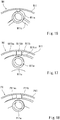
- an inner portion L11c is an annular plate continuous with the radially inner portion of each of front pin support portions L11a.
- Modified Example 12 is different from Modified Example 1 in that the inner coupling portions A11ca are omitted.
- an inner portion M11c is continuous with the radially inner portion of each of front pin support portions M11a and linearly connects the front pin support portions M11a to each other.
- a portion of the inner portion, connecting the front pin support portions M11a to each other, may be curved.
- an outer portion N11b includes an annular portion N11bc which is continuous with the radially outer portion of each of front pin support portions N11a, and a coupling portion N11bb coupling the annular portion N11bc to an outer peripheral portion N11ba at a location that is radially outward of the front pin support portion N11a.
- An inner portion N11c is an annular plate which is continuous with the annular portion N11bc of the outer portion N11b and is continuous with the radially inner portion of the front pin support portion N11a.
- an outer portion P11b is the same as that of Modified Example 14, while an inner portion is an opening.
- an annular plate P11bc coupled to each of front pin support portions P11a is disposed radially outward of the radially inner end portion of the front pin support portion P11a.
- the openings formed in regions other than the front pin support portions of the front plate and the rear shaft support portions of the rear plate may be thin regions (thin plates) which do not substantially contribute to a stiffness.
- the thickness of the thin regions which do not substantially contribute to a stiffness is set to be less than 20% of the maximum (largest) thickness, and less than 5mm.
- the openings formed in the regions other than the front pin support portions of the front plate of Fig. 2 , and the rear shaft support portions of the rear plate of Fig. 3 may be the thin regions (thin plates), and the opening formed in each of the regions other than the front pin support portions of the front plates of Figs. 4 to 10 , 13 , and 15 to 18 may be the thin region.
- the non-thin region rate of the outer portion of the front plate may be set to be less than that of the outer portion of the rear plate.
- the non-thin region rate of the inner portion of the front plate may be set to be more than that of the outer portion of the rear plate.
- a front plate T11 of a carrier T6 may have a plate portion crossing the rotational axis line of the carrier T6, in its center portion.
- the center opening through which the rotational axis line of the carrier T6 passes is not formed in the front plate T11 of the carrier T6.
- an inner portion T11c of the front plate T11 has a star shape coupling front pin support portions T11a to each other, at a location that is radially inward of the front pin support portions T11a.
- the inner portion T11c has a shape in which arms extend radially from a center member formed continuously in the circumferential direction around the rotational axis line of the carrier T6 and having no opening, toward the front pin support portions T11a.
- the inner portion T11c includes an outer peripheral portion T11ca extending along its contour, and a body T11cb which is radially inward of the outer peripheral portion T11ca.
- the outer peripheral portion T11ca has a thickness larger than that of the body T11cb.
- the body T11cb of the inner portion T11c has a thickness more than 50% of the thickness of the outer peripheral portion T11ca.
- the thickness of the body T11cb is more than 10mm.
- the body T11cb may be a thin region which does not substantially contribute to a stiffness.
- the thickness of the body T11cb and the thickness of the outer peripheral portion T11ca may be equal to each other. Further, the thickness of the body T11cb may be larger than that of the outer peripheral portion T11ca.
- the outer peripheral portion T11ca has a thickness larger than that of the body T11cb, like the present modified example, it becomes easy to ensure a stiffness of the inner portion T11c with respect to a radial tensile force, while reducing a weight. Since the inner portion T11c is not formed with the center opening, lubricating oil can be easily reserved in the inner space of the carrier T6.
- the inner portion T11c is not formed with the center opening, it becomes possible to efficiently improve the radial tensile force of the front plate T11.
- the reduction of the weight of the front plate T11 can be suitably realized.
- the opening of an outer portion T11b may be closed by a thin portion.
- the configuration of Fig. 19 may be applied to the above-described modified examples.
- Fig. 20 is a cross-sectional view of major constituents of a carrier 106, planetary gears 3, planetary pins 5, and an output frame 107 according to Embodiment 2.
- the planetary gear reduction device includes the carrier 106 which is rotatable (revolvable).
- both of the carrier and the ring gear may be rotatable, or only the carrier may be rotatable and the ring gear may be unrotatable.
- the carrier 106 includes a front plate 111, a rear plate 112, and a coupling member 113.
- the front plate 111 includes a plurality of front pin support portions 111a formed with front pin support surfaces 111aa supporting the first end portions of the plurality of planetary pins 5, respectively.
- the rear plate 112 includes a plurality of rear shaft support portions 112a formed with rear shaft support surfaces 112aa supporting the second end portions of the plurality of planetary pins 5, respectively.
- the coupling member 113 couples the radially outer end portion of the front plate 111 to the radially outer end portion of the rear plate 112.
- the output frame 107 is connected to a portion of the coupling member 113, the portion being closer to the front plate 111.
- the output frame 107 is connected to a portion of the coupling member 113, the portion being closer to the front plate 111 than to a center in the direction of the axis line X, by a fastening member B2 (e.g., bolt or rivet).
- a fastening member B2 e.g., bolt or rivet
- the output frame 107 may be integrated with the coupling member 113.
- the coupling member 113 includes a front portion 113a provided at a location that is closer to the front plate 111 than to a location where the coupling member 113 is connected to the output frame 107, and a rear portion 113b provided at a location that is closer to the rear plate 112 than to the location where the coupling member 113 is connected to the output frame 107.
- a portion (external force transmission path) of the carrier 106, which is between front pin support surfaces 111aa and the output frame 107 is defined as a first region R101.
- a portion (external force transmission path) of the carrier 106, which is between rear shaft support surfaces 112aa and the output frame 107 is defined as a second region R102.
- a portion of the front plate 111 which is radially outward of the centers of the front pin support surfaces 111aa and the front portion 113a of the coupling member 113 form the first region R101
- a portion of the rear plate 112 which is radially outward of the centers of the rear shaft support surfaces 112aa and the rear portion 113b of the coupling member 113 form the second region R102.
- a portion of the front plate 111, the portion being outward of a pitch circle connecting the center axes of the planetary pins 5, and the front portion 113a of the coupling member 113 form the first region R101.
- a portion of the rear plate 112, the portion being outward of the pitch circle connecting the center axes of the planetary pins 5, and the rear portion 113b of the coupling members 113 form the second region R102.
- the front portion 113a includes a flexible structure portion QF which can make the stiffness with respect to the twist force lower than that of the rear portion 113b.
- the flexible structure portion QF is formed by making the minimum (smallest) thickness of the front portion 113a smaller than that of the rear portion 113b.
- the flexible structure portion QF may have other configurations, in which the cross-sectional area, which is viewed in the direction of the axis line X, is smaller than that of the rear portion 113b (e.g., the circumferential width of the flexible structure portion QF is smaller than that of the rear portion 113b).
- the flexible structure portion QF may be made of a material with a stiffness lower than that of the rear portion 113b.
- the flexible structure portion QF may be formed by making the opening rate larger than that of the rear portion 113b.
- the carrier 106 has a shape in which the stiffness of the first region R101 with respect the twist force and the stiffness of the second region R102 with respect the twist force are equal to each other.
- the front plate 111 and the rear plate 112 are made of the same material, and have the same shape and an equal size.
- the stiffness with respect to the radial tensile force applied to the front pin support surfaces 111aa and the stiffness with respect to the radial tensile force applied to the rear shaft support surfaces 112aa are equal to each other.
- the carrier 106 can be easily formed to have a configuration in which the stiffness of the first region R101 with respect the twist force and the stiffness of the second region R102 with respect the twist force are equal to each other.
- a misalignment angle of each of the planetary pins 5 with respect to the axis line X can be made less than 0.1 degree.
- the coupling member 113 serves to reduce the twist stiffness in the first region R101 of the carrier 106, designing of the front plate 111 can be simplified. Further, since the front plate 111 and the rear plate 112 have the same shape, the front plate 111 and the rear plate 112 can be easily designed.
- the other constituents are the same as those of Embodiment 1 and will not be described in repetition.
- the present invention is not limited to the above-described embodiments and modified examples.
- the configurations may be changed, added or deleted.
- the embodiments and the modified examples may be combined as desired.
- a part of constituents of one embodiment or example may be applied to another embodiment or example.
- the constituents of Embodiment 1 and the constituents of Embodiment 2 may be combined.
- the stiffness may be adjusted by changing the shape and/or material between the front plate and the rear plate.
Landscapes
- Engineering & Computer Science (AREA)
- General Engineering & Computer Science (AREA)
- Mechanical Engineering (AREA)
- Retarders (AREA)
Abstract
Description
- The present invention relates to a planetary gear reduction device including a rotatable carrier.
- In a planetary gear reduction device used in a driving force transmission mechanism in aircraft or the like, in some cases, planetary pins are bent due to driving torque applied to a carrier, parallelism of planetary gears with respect to a sun gear and a ring gear is reduced, and misalignment of meshing of the gears occurs. As a solution to this, in the planetary gear reduction device disclosed in
Patent Literature 1, a front plate of the carrier, which supports one end portions of the planetary pins, is provided with a hollow space to reduce stiffness of the front plate. In this way, bending deformation of the planetary pins is suppressed. - Patent Literature 1: Japanese Laid-Open Patent Application Publication No.
2011-94714 - In the planetary gear reduction device disclosed in
Patent Literature 1, in a case where the carrier is rotatable (e.g., in the case of a planetary gear reduction device), the driving torque transmitted to the carrier increases. In particular, in a case where a location (force application point of the carrier) from which the driving torque is output from the carrier is closer to the front plate, imbalanced twist deformation may occur in the carrier due to a torque reaction force, the planetary pins may be tilted (inclined), and misalignment may occur. - In the planetary gear reduction device including the rotatable carrier, a centrifugal force of the planetary gears and the planetary pins is applied to the carrier. In the configuration disclosed in
Patent Literature 1, the stiffness of the front plate is made lower than that of a rear plate. Therefore, due to the centrifugal force, radially outward tensile deformation of the front plate occurs. For this reason, the planetary pins may be tilted (inclined) and misalignment may occur due to the centrifugal force. - In view of the above-described circumstances, an object of the present invention is to prevent misalignment due to the torque transmitted to the carrier and misalignment due to the centrifugal force of the planetary gears and the planetary pins, in the planetary gear reduction device including the rotatable carrier.
- According to a first aspect of the present invention, a planetary gear reduction device comprises a sun gear which receives a driving force as an input, the sun gear having external teeth; a plurality of planetary gears having external teeth which mesh with the sun gear; a ring gear having internal teeth which mesh with the plurality of planetary gears; a rotatable carrier including: a front plate including a plurality of front pin support surfaces supporting first end portions of a plurality of planetary pins, the planetary pins being axes of rotation of the plurality of planetary gears, a rear plate including a plurality of rear shaft support surfaces supporting second end portions of the plurality of planetary pins, and a coupling member coupling the front plate to the rear plate; and an output frame connected to the carrier to output the driving force, wherein the output frame is connected to a portion of a radially outer portion of the carrier, the portion being closer to the front plate than to the rear plate, wherein the carrier has a first region as an external force transmission path between the front pin support surfaces and the output frame, and a second region as the external force transmission path between the rear shaft support surfaces and the output frame, and a stiffness with respect to a twist force of the first region and a stiffness with respect to the twist force of the second region are equal to each other, and wherein in the front plate and the rear plate, a stiffness with respect to a radial tensile force applied to the front pin support surfaces and a stiffness with respect to the radial tensile force applied to the rear shaft support surfaces are equal to each other (equalized).
- In accordance with this configuration, the output frame is connected to a portion of the radially outer portion of the carrier, the portion being closer to the front plate than to the rear plate. In a case where no measures are taken, a torque reaction force from the output frame to the carrier, which is generated at the front plate side, is more than that generated at the rear plate side. However, the stiffness with respect to the twist force of the first region and the stiffness with respect to the twist force of the second region are equal to each other. Therefore, a twist deformation generated in the carrier due to the torque transmitted to the carrier is balanced when viewed from the planetary pins, and tilting (inclination) of the planetary pins is prevented. In a case where the twist stiffness of the first region and the twist stiffness of the second region are equalized in the carrier, the twist stiffness of the front plate and the twist stiffness of the rear plate are different from each other. However, in the front plate and the rear plate, the stiffness with respect to the radial tensile force applied to the front pin support surfaces and the stiffness with respect to the radial tensile force applied to the rear shaft support surfaces are equal to each other (equalized). This makes it possible to prevent tilting (inclination) of the planetary pins due to the centrifugal force. As a result, in the planetary gear reduction device including the rotatable carrier, it becomes possible to prevent misalignment due to the torque transmitted to the carrier and misalignment due to the centrifugal force of the planetary gears and the planetary pins.
- The front plate may include an outer portion which is radially outward of centers of the plurality of planetary pins, the rear plate includes an outer portion which is radially outward of the centers of the plurality of planetary pins, and the outer portion of the front plate includes a flexible structure portion which makes the stiffness with respect to the twist force lower than that of the outer portion of the rear plate, and the stiffness with respect to the radial tensile force of a region of the front plate, the region being inward of the flexible structure portion, may be higher than that of a region of the rear plate, the region being radially inward of a portion of the rear plate, the portion conforming in radial position to the flexible structure portion.
- In accordance with this configuration, the outer portion of the front plate includes the flexible structure portion which makes the twist stiffness lower than that of the outer portion of the rear plate. With the flexible structure portion, the twist stiffness of the first region and the twist stiffness of the second region can be easily equalized. The tensile stiffness of the outer portion of the front plate is reduced because of the flexible structure portion provided at the outer portion of the front plate. However, by increasing the tensile stiffness of a region of the front plate, the region being radially inward of the flexible structure portion, it becomes possible to easily realize a configuration in which the stiffness of the front plate with respect to the centrifugal force and the stiffness of the rear plate with respect to the centrifugal force are equal to each other. In brief, the twist deformation can be substantially prevented by the radially outer portion of the carrier, and the misalignment due to the centrifugal force can be substantially prevented by the radially inner portion of the carrier. Thus, designing for prevention of the twist information and designing for prevention of the misalignment can be easily separately performed.
- At least one of a non-opening rate, a non-thin region rate, a minimum thickness, and a material stiffness, of the outer portion of the front plate, may be made smaller than that of the outer portion of the rear plate, to form the flexible structure portion.
- In accordance with this configuration, the flexible structure portion can be easily formed in the front plate.
- A non-opening rate, a non-thin region rate, or a minimum thickness of the outer portion of the front plate may be smaller than that of the outer portion of the rear plate. The front plate may include an inner portion which is radially inward of centers of the plurality of planetary pins, the rear plate includes an inner portion which is radially inward of the centers of the plurality of planetary pins, and the non-opening rate, the non-thin region rate, or the minimum thickness of the inner portion of the front plate may be larger than that of the inner portion of the rear plate.
- This makes it possible to suitably realize reduction of the weight of the carrier and equalization of the stiffness of the front plate and the stiffness of the rear plate.
- A region of the front plate, the region having a highest stiffness with respect to the radial tensile force, may be located radially inward of a region of the rear plate, the region having a highest stiffness with respect to the radial tensile force. For example, in a case where the front plate includes a plurality of regions which are different in thickness, the largest thickness portion of the plurality of regions corresponds to the region with a highest stiffness with respect to the radial tensile force.
- In accordance with this configuration, even in a case where the tensile stiffness of the first region of the front plate is reduced, the stiffness with respect to the radial tensile force of the front plate can be easily increased. As a result, designing and manufacturing can be made easier.
- Each of the front plate and the rear plate may have a center opening through which a rotational axis line of the carrier passes, and the center opening of the front plate may be smaller than the center opening of the rear plate.
- In accordance with this configuration, even in a case where the tensile stiffness of the first region of the front plate is reduced, the stiffness with respect to the radial tensile force of the front plate can be easily increased. As a result, designing and manufacturing can be made easier.
- The front plate may include a plate portion crossing a rotational axis line of the carrier, in a center portion of the front plate.
- In accordance with this configuration, since the front plate is not formed with the center opening crossing the rotational axis line of the carrier, lubricating oil can be easily reserved in the inner space of the carrier. Since the front plate is not formed with the center opening, it becomes possible to efficiently improve the radial tensile force of the front plate. The reduction of the weight of the front plate can be suitably realized.
- The output frame may be connected to a portion of the coupling member, the portion being closer to the front plate, the coupling member may include a front portion provided at a location that is closer to the front plate than to a location where the coupling member is connected to the output frame, and a rear portion provided at a location that is closer to the rear plate than to the location where the coupling member is connected to the output frame, and the front portion may be configured to make the stiffness with respect to the twist force lower than that of the rear portion.
- In accordance with this configuration, the stiffness of the first region and the stiffness of the second region can be easily equalized in the carrier. Since the coupling member serves to reduce the twist stiffness in the first region of the carrier, designing of the front plate can be simplified.
- The front plate and the rear plate may have the same shape.
- In accordance with this configuration, the front plate and the rear plate can be easily designed.
- In accordance with the present invention, it becomes possible to prevent misalignment due to the torque transmitted to the carrier and misalignment due to the centrifugal force of the planetary gears and the planetary pins, in the planetary gear reduction device including the rotatable carrier.
-
-
Fig. 1 is a partial cross-sectional view of a planetary gear reduction device according toEmbodiment 1. -
Fig. 2 is a perspective view of planetary gears, planetary pins, a carrier, and an output frame of the planetary gear reduction device ofFig. 1 , which are seen from a front plate. -
Fig. 3 is a perspective view of the planetary gears, the planetary pins, the carrier, and the output frame ofFig. 2 , which are seen from a rear plate. -
Fig. 4 is a partially enlarged perspective view of a carrier according to Modified Example 1. -
Fig. 5 is a partially enlarged perspective view of a carrier according to Modified Example 2. -
Fig. 6 is a partially enlarged perspective view of a carrier according to Modified Example 3. -
Fig. 7 is a partially enlarged perspective view of a carrier according to Modified Example 4. -
Fig. 8 is a partially enlarged perspective view of a carrier according to Modified Example 5. -
Fig. 9 is a partially enlarged perspective view of a carrier according to Modified Example 6. -
Fig. 10 is a partially enlarged perspective view of a carrier according to Modified Example 7. -
Fig. 11 is a partially enlarged perspective view of a carrier according to Modified Example 8. -
Fig. 12 is a partially enlarged perspective view of a carrier according to Modified Example 9. -
Fig. 13 is a partially enlarged perspective view of a carrier according to Modified Example 10. -
Fig. 14 is a partially enlarged perspective view of a carrier according to Modified Example 11. -
Fig. 15 is a partially enlarged perspective view of a carrier according to Modified Example 12. -
Fig. 16 is a partially enlarged perspective view of a carrier according to Modified Example 13. -
Fig. 17 is a partially enlarged perspective view of a carrier according to Modified Example 14. -
Fig. 18 is a partially enlarged perspective view of a carrier according to Modified Example 15. -
Fig. 19 is a perspective view of a carrier according to Modified Example 16. -
Fig. 20 is a cross-sectional view of major constituents of a carrier, planetary gears, planetary pins, and an output frame according toEmbodiment 2. - Hereinafter, the embodiments will be described with reference to the drawings. For easier understanding of the description, a side which is closer to an
output frame 7 of a planetarygear reduction device 1 in the direction of a rotational axis line will be referred to as "front" and a side which is distant from theoutput frame 7 will be referred to as "rear". However, front-rear relation is not limited to this. -
Fig. 1 is a partial cross-sectional view of a planetarygear reduction device 1 according toEmbodiment 1. In the present embodiment, the planetarygear reduction device 1 is used as, for example a driving force transmission mechanism (speed reduction mechanism) of an aircraft engine or the like. As shown inFig. 1 , the planetarygear reduction device 1 includes asun gear 2, a plurality ofplanetary gears 3, aring gear 4, a plurality ofplanetary pins 5, acarrier 6, and theoutput frame 7. - The
sun gear 2 hasexternal teeth 2a. Thesun gear 2 is mounted on aninput shaft 8 by fitting or spline coupling so that thesun gear 2 is rotatable together with theinput shaft 8. A rotational driving force is transmitted from an engine to theinput shaft 8. The plurality ofplanetary gears 3 includeexternal teeth 3a which mesh with theexternal teeth 2a of thesun gear 2. The plurality ofplanetary gears 3 are disposed to be equally spaced apart from each other (positioned at equidistant locations) around an axis line X of thesun gear 2. Thering gear 4 includesinternal teeth 4a which mesh with theexternal teeth 3a of theplanetary gears 3, and afastening flange 4b. Thering gear 4 is unrotatably fastened at theflange 4b. Note that theflange 4b may be omitted so long as thering gear 4 is unrotatably fastened (fixed). The plurality ofplanetary pins 5 are rotatably inserted into the plurality ofplanetary gears 3 viabearings 9, respectively, to support the plurality ofplanetary gears 3. Each of theplanetary gears 3 is constituted by double teeth rows. Alternatively, each of theplanetary gears 3 may be a single teeth row, or three or more teeth rows. - The
carrier 6 includes thefront plate 11, therear plate 12, and a plurality ofcoupling members 13. Thefront plate 11 includes a plurality of frontpin support portions 11a formed with front pin support surfaces 11aa supporting the first end portions of the plurality ofplanetary pins 5, respectively. Therear plate 12 includes a plurality of rearshaft support portions 12a formed with rear shaft support surfaces 12aa supporting the second end portions of the plurality ofplanetary pins 5, respectively. Each of the frontpin support portions 11a and the rearshaft support portions 12a has a cylindrical (tubular) shape. The front pin support surfaces 11aa and the rear shaft support surfaces 12aa are tubular surfaces. Alternatively, each of the frontpin support portions 11a and the rearshaft support portions 12a may not have the cylindrical shape and may have a, for example, tubular shape with a rectangular cross-section. Theplanetary pins 5 are inserted into the frontpin support portions 11a and the rearshaft support portions 12a. The frontpin support portions 11a and the rearshaft support portions 12a may not protrude with a tubular shape in a direction of the axis line X so long as the front pin support surfaces 11aa and the rear shaft support surfaces 12aa have a tubular shape. The frontpin support portions 11a and the rearshaft support portions 12a may be coplanar (flush) with surfaces (e.g., surfaces of an outer portion and an inner portion (described later), facing in the direction of the axis line X) adjacent to them. - Each of the plurality of
coupling members 13 has a post shape. The plurality ofcoupling members 13 couple the radially outer end portion of thefront plate 11 to the radially outer end portion of therear plate 12. The plurality ofcoupling members 13 are arranged with gaps G (seeFig. 2 ) in the circumferential direction around the axis line X. Theplanetary gears 3 are exposed through the gaps G. Specifically, theinternal teeth 4a of thering gear 4 mesh with theexternal teeth 3a of theplanetary gears 3 through the gaps G each of which is betweenadjacent coupling members 13. Note that the shape of the coupling members is not limited so long as the gaps G through which theplanetary gears 3 are exposed. - The
output frame 7 is connected to the radially outer portion of thecarrier 6. Theoutput frame 7 is configured to output a rotational driving force from thecarrier 6. Theoutput frame 7 is connected to a portion of the radially outer portion of thecarrier 6, the portion being closer to thefront plate 11 than to therear plate 12. In the present embodiment, theoutput frame 7 is connected to thefront plate 11. Theoutput frame 7 includes atubular portion 7a protruding in the direction of the axis line X from an end surface of the outer peripheral portion of thecarrier 6, the end surface being closer to thefront frame 11, and aflange 7b protruding radially outward from a protruding end of thetubular portion 7a. Theoutput frame 7 is integrated with thecarrier 6. The radial position of thetubular portion 7a conforms to those of thecoupling members 13. A driven member (e.g., shaft of a fan) (not shown) is secured to theflange 7b. The shape of theoutput frame 7 is not particularly limited so long as theoutput frame 7 is secured to the driven member so that the driving force can be transmitted to the driven member. Theoutput frame 7 may be fastened to thecarrier 6 by a fastening member. - In the planetary
gear reduction device 1, the rotational driving force from theinput shaft 8 is input to thesun gear 2 in a state in which thering gear 4 is unrotatably fastened (fixed), theplanetary gears 3 rotate (rotate around their axes) around theplanetary pins 5, and thecarrier 6 rotates (revolves) around the axis line X of thesun gear 2. In the present embodiment, thecarrier 6 rotates at a high speed equal to or higher than 1000rpm. The rotational driving force of thecarrier 6 is output to the driven member via theoutput frame 7. In the planetarygear reduction device 1 with the above-described configuration, thering gear 4 does not rotate and thecarrier 6 rotates. Therefore, a reduction gear ratio increases and the driving torque transmitted to thecarrier 6 increases. Alternatively, in the planetary gear reduction device, both of the carrier and the ring gear may be rotatable. This is especially effective to the planetary gear reduction device in which a great centrifugal force is applied to the planetary gears and the planetary pins, like the planetary gear speed reducer. -
Fig. 2 is a perspective view of theplanetary gears 3, theplanetary pins 5, thecarrier 6, and theoutput frame 7 of the planetarygear reduction device 1 ofFig. 1 , which are seen from thefront plate 11.Fig. 3 is a perspective view of theplanetary gears 3, theplanetary pins 5, thecarrier 6, and theoutput frame 7 ofFig. 2 , which are seen from therear plate 12. In the example ofFigs. 2 and3 , theexternal teeth 3a of theplanetary gears 3 are omitted. As shown inFigs. 2 and3 , thefront plate 11 includes the frontpin support portions 11a, anouter portion 11b which is radially outward of the centers of the frontpin support portions 11a (the centers of the planetary pins 5), and aninner portion 11c which is radially inward of the centers of the frontpin support portions 11a. Therear plate 12 includes the rearshaft support portions 12a, anouter portion 12b which is radially outward of the centers of the rearshaft support portions 12a (the centers of the planetary pins 5), and aninner portion 12c which is radially inward of the centers of the rearshaft support portions 12a. - A portion (external force transmission path) of the
carrier 6, which is between the front pin support surfaces 11aa and theoutput frame 7 is defined as a first region R1. A portion (external force transmission path) of thecarrier 6, which is between the rear shaft support surfaces 12aa and theoutput frame 7 is defined as a second region R2. In the present embodiment, a portion of thefront plate 11 which is radially outward of the centers of the frontpin support portions 11a forms the first region R1, while a portion of therear plate 12 which is radially outward of the centers of the rearshaft support portions 12a and thecoupling members 13, form the second region R2. More specifically, a portion of thefront plate 11, the portion being outward of a pitch circle connecting the center axes of theplanetary pins 5, forms the first region R1. A portion of therear plate 12, the portion being outward of the pitch circle connecting the center axes of theplanetary pins 5, and thecoupling members 13, form the second region R2. - The
carrier 6 has a shape in which a stiffness of the first region R1 with respect a twist force and a stiffness of the second region R2 with respect a twist force are equal to each other. The twist force means a force applied in a direction in which thecarrier 6 is twisted around the axis line X. - Specifically, the
outer portion 11b of thefront plate 11 includes a flexible structure portion F which makes the stiffness with respect to the twist force lower than that of theouter portion 12b of therear plate 12. The flexible structure portion F may be formed by increasing the opening rate of theouter portion 11b. Further, the flexible structure portion F may be formed by making the thickness of theouter portion 11b in the direction of the axis line X smaller than that of theinner portion 11c. In the present embodiment, the flexible structure portion F is formed by setting the opening rate of theouter portion 11b to be more than 50% and by making the thickness of theouter portion 11b in the direction of the axis line X smaller than that of theinner portion 11c. The flexible structure portion F is comprised of a plurality of coupling portions 11bb coupling an outer peripheral portion 11ba of theouter portion 11b, extending along the outer periphery of thecarrier 6, to the frontpin support portions 11a. The plurality of coupling portions 11bb are arranged to be spaced apart from each other in the circumferential direction. The plurality of coupling portions 11bb have a sector shape in which a circumferential width increases toward a radially outer (outward) side, when viewed from the direction of the axis line X. - The stiffness with respect the twist force, of the
outer portion 12b of therear plate 12 is higher than that of theouter portion 11b of thefront plate 11. The opening rate of theouter portion 12b of therear plate 12 is less than that of theouter portion 11b of thefront plate 11. Alternatively, theouter portion 12b of therear plate 12 may have a minimum (smallest) thickness larger than that of theouter portion 11b of thefront plate 11. - In this configuration, a distance from the
output frame 7 to the front pin support surfaces 11aa of thecarrier 6 is shorter than a distance from theoutput frame 7 to the rear shaft support surfaces 12aa of thecarrier 6 through thecoupling members 13. However, by the flexible structure portion F, the stiffness with respect the twist force of theouter portion 11b of thefront plate 11 is lower than that of theouter portion 12b of therear plate 12. Therefore, the stiffness of the first region R1 with respect the twist force and the stiffness of the second region R2 with respect the twist force are equal to each other. - The
front plate 11 and therear plate 12 have shapes in which a stiffness with respect to a radial tensile force applied to the front pin support surfaces 11aa and a stiffness with respect to a radial tensile force applied to the rear shaft support surfaces 12aa are equal to each other (equalized). Specifically, the stiffness with respect to the radial tensile force, of theouter portion 11b of thefront plate 11, is lower than that of theouter portion 12b of therear plate 12. The stiffness with respect to the radial tensile force of a region of thefront plate 11, the region being radially inward of the flexible structure portion F, is higher than that of a region of therear plate 12, the region being radially inward of a portion of therear plate 12, the portion conforming in radial position to the flexible structure portion F. - The
inner portion 11c of thefront plate 11 has a star shape coupling the frontpin support portions 11a to each other at locations that are radially inward of the frontpin support portions 11a. Theinner portion 11c has a center opening S1 through which the axis line X passes. Specifically, theinner portion 11c has a shape in which arms radially extend from a center member (e.g., ring member) formed continuously in the circumferential direction around the axis line X toward the frontpin support portions 11a. The stiffness with respect to the radial tensile force, of theinner portion 11c of thefront plate 11, is higher than that of theouter portion 11b of thefront plate 11. Theinner portion 12c of therear plate 12 linearly couples the rearshaft support portions 12a, at locations where the radial position of theinner portion 12c overlaps with those of the radially inner portions of the rear shaft support surfaces 12a. Theinner portion 12c has a center opening S2 through which the axis line X passes. - A region having a highest stiffness with respect to the radial tensile force, of the
front plate 11, is located radially inward of a region having a highest stiffness with respect to the radial tensile force, of therear plate 12. In the present embodiment, a region having a highest stiffness with respect to the radial tensile force, of a region coupling the frontpin support portions 11a to each other, in thefront plate 11, is located radially inward of a region having a highest stiffness with respect to the radial tensile force, of a region coupling the rearshaft support portions 12a to each other, in therear plate 12. - Specifically, the
inner portion 12c of therear plate 12 has a thickness in the direction of the axis line X which is equal to that of theinner portion 11c of thefront plate 11. The center opening S1 of thefront plate 11 is smaller than the center opening S2 of therear plate 12, when viewed in the direction of the axis line X. An opening rate of theinner portion 11c of thefront plate 11 is less than that of theinner portion 12c of therear plate 12. Theinner portion 11c of thefront plate 11, may have a minimum (smallest) thickness larger than that of theinner portion 12c of therear plate 12. Further, theinner portion 11c of thefront plate 11, may have a minimum (smallest) thickness and a non-opening rate which are less than those of theinner portion 12c of therear plate 12. - In accordance with this configuration, the stiffness with respect the twist force of the
outer portion 11b of thefront plate 11 is lower than that of theouter portion 12b of therear plate 12, whereas the stiffness with respect to the radial tensile force, of theinner portion 11c of thefront plate 11, is higher than that of theinner portion 12c of therear plate 12. Therefore, thecarrier 6 can be configured so that the stiffness with respect to the radial tensile force applied to the front pin support surfaces 11aa of thefront plate 11 and the stiffness with respect to the radial tensile force applied to the rear shaft support surfaces 12aa of therear plate 12 are equal to each other. - In accordance with the above-described configuration, the
output frame 7 is connected to a portion of the radially outer portion of thecarrier 6, the portion being closer to thefront plate 11 than to therear plate 12. Therefore, in a case where no measures are taken, a torque reaction force from theoutput frame 7 to thecarrier 6, which is generated at thefront plate 11 side is more than that generated at therear plate 12 side. However, in thecarrier 6, the stiffness of the first region R1 with respect the twist force and the stiffness of the second region R2 with respect the twist force are equal to each other. Therefore, a twist deformation generated in thecarrier 6 due to the torque transmitted to thecarrier 6 is balanced when viewed from theplanetary pins 5, and tilting (inclination) of theplanetary pins 5 is prevented. In a case where the twist stiffness of the first region R1 and the twist stiffness of the second region R2 are equalized in thecarrier 6, the twist stiffness of thefront plate 11 and the twist stiffness of therear plate 12 are different from each other. However, in thefront plate 11 and therear plate 12, the stiffness with respect to the radial tensile force applied to the front pin support surfaces 11aa and the stiffness with respect to the radial tensile force applied to the rear shaft support surfaces 12aa are equal to each other. This makes it possible to prevent tilting (inclination) of theplanetary pins 5 due to the centrifugal force. As a result, in the planetarygear reduction device 1, it becomes possible to prevent misalignment due to the torque transmitted to thecarrier 6 and misalignment due to the centrifugal force of theplanetary gears 3 and the planetary pins 5. In accordance with the present embodiment, the stiffness of the first region R1 with respect the twist force and the stiffness of the second region R2 with respect the twist force are equalized in thecarrier 6, and the stiffness with respect to the radial tensile force applied to the front pin support surfaces 11aa and the stiffness with respect to the radial tensile force applied to the rear shaft support surfaces 12aa are equal to each other. This allows a misalignment angle of each of theplanetary pins 5 with respect to the axis line X to be less than 0.1 degree, even when thecarrier 6 rotates at 1000rpm or higher. - In the
carrier 6, theouter portion 11b of thefront plate 11 includes the flexible structure portion F which makes the twist stiffness lower than that of theouter portion 12b of therear plate 12. With the flexible structure portion F, the twist stiffness of the first region R1 and the twist stiffness of the second region R2 can be easily equalized. The stiffness with respect to the radial tensile force of theouter portion 11b of thefront plate 11 is reduced because of the flexible structure portion F provided at theouter portion 11b of thefront plate 11. However, in this case, by increasing the stiffness with respect to the radial tensile force of a region of thefront plate 11,the region being radially inward of the flexible structure portion F, it becomes possible to easily realize a configuration in which the stiffness of thefront plate 11 with respect to the centrifugal force and the stiffness of therear plate 12 with respect to the centrifugal force are equal to each other. In brief, the twist deformation can be substantially prevented by the radially outer portion of thecarrier 6, and the misalignment due to the centrifugal force can be substantially prevented by the radially inner portion of thecarrier 6. Thus, designing for prevention of the twist information and designing for prevention of the misalignment can be easily separately performed. - The opening rate of the
outer portion 11b of thefront plate 11 is set to be larger than that of theouter portion 12b of therear plate 12. The thickness of theouter portion 11b of thefront plate 11 is set to be smaller than that of theouter portion 12b of therear plate 12. This allows thefront plate 11 to be easily formed with the flexible structure portion F. - The opening rate of the
outer portion 11b of thefront plate 11 is set to be larger than that of theouter portion 12b of therear plate 12. The opening rate of theinner portion 12c of therear plate 12 is set to be smaller than that of theinner portion 11c of thefront plate 11. This makes it possible to suitably realize reduction of the weight of thecarrier 6 and equalization of the stiffness of thefront plate 11 and the stiffness of therear plate 12. - In the
carrier 6, the twist stiffness of the first region R1 of thefront plate 11 is reduced so that the twist stiffness of the first region R1 and the twist stiffness of the second region R2 become equal to each other, and hence the stiffness with respect to the radial tensile force of the first region R1 of thefront plate 11 is reduced. However, since the center opening S1 of thefront plate 11 is smaller than the center opening S2 of therear plate 12, the stiffness with respect to the radial tensile force of thefront plate 11 is easily increased. In this way, designing and manufacturing can be made easier. -
Figs. 4 to 19 show variations of the front plate of the carrier which can realize equalization of the stiffness with respect to the twist force and equalization of the stiffness with respect to the radial tensile force. Note that the shapes of Modified Examples are applicable to the rear plate so long as the carrier can realize equalization of the stiffness with respect to the twist force and equalization of the stiffness with respect to the radial tensile force. In that case, the shape of the front plate and the shape of the rear plate may be different from each other. In Modified Examples, the same constituents as those ofEmbodiment 1 will not be described in repetition. - As shown in
Fig. 4 , a front plate A11 of a carrier 6A according to Modified Example 1 includes front pin support portions A11a, an outer portion A11b which is radially outward of the centers of the front pin support portions A11a (the centers of the planetary pins), and an inner portion A11c which is radially inward of the centers of the front pin support portions A11a. The outer portion A11b includes a flexible structure portion AF which makes a stiffness with respect to a twist force lower than that of the outer portion of the rear plate (not shown). - The flexible structure portion AF is comprised of an outer coupling portion A11bb coupling an outer peripheral portion A11ba extending along the outer periphery of the carrier A6, of the outer portion A11b, to each of the front pin support portions A11a. The inner portion A11c includes an annular portion A11ca extending in the circumferential direction at a location that is radially inward of the front pin support portions A11a, and inner coupling portions A11cb coupling the front pin support portions A11a to the annular portion A11ca. When viewed in the direction of the axis line, the outer coupling portion A11bb has a width smaller than that of the inner coupling portion A11cb. The outer coupling portions A11bb has a thickness in the direction of the axis line which is smaller than that of the inner coupling portion A11cb. The flexible structure portion AF is formed by performing setting so that the non-opening rate and minimum (smallest) thickness of the outer portion A11b of the front plate A11 are less than those of the outer portion of the rear plate (not shown). The other constituents are the same as those of
Embodiment 1 and will not be described in repetition. - As shown in
Fig. 5 , in a front plate B11 of a carrier B6 according to Modified Example 2, a flexible structure portion BF is comprised of a pair of outer coupling portions B11bb coupling each of front pin support portions B11a to an outer peripheral portion B11ba. A clearance (gap) is formed between the pair of outer coupling portions B11bb. In Modified Example 2, the outer coupling portions B11bb are different from those of Modified Example 1. Alternatively, instead of the configuration in which the clearance (gap) is formed between the pair of outer coupling portions B11bb, one outer coupling portion may be provided with a hole or a depressed (recessed) portion, or one coupling portion may have a hollow space. - As shown in
Fig. 6 , in a front plate C11 of a carrier C6 according to Modified Example 3, a flexible structure portion CF is comprised of an outer coupling portion C11bb coupling each of front pin support portions C11a to an outer peripheral portion C11ba, and the outer coupling portion C11bb has a curved shape with a flexion point. In Modified Example 3, the outer coupling portion C11bb is different from that of Modified Example 1. - As shown in
Fig. 7 , in a front plate D11 of a carrier D6 according to Modified Example 4, a flexible structure portion DF is comprised of an outer coupling portion D11bb coupling each of front pin support portions D11a to an outer peripheral portion D11ba, and the outer coupling portion D11bb includes a joint portion. Specifically, in the joint portion, a first plate Da integrated with each of the front pin support portions D11a and protruding radially outward, and a second plate Db integrated with the outer peripheral portion D11ba and protruding radially inward are lapped to each other and fastened to each other by use of a fastening member B1 (e.g., bolt or rivet). In Modified Example 4, the outer coupling portion D11bb is different from that of Modified Example 1. Note that the first plate Da and the second plate Db may be made of different materials (e.g., materials which are different in stiffness). Further, the joint portion is not limited to fastening and may be welding. In the present Modified Example, the stiffness with respect to the twist force can be adjusted by changing the fastening structure. - As shown in
Fig. 8 , in a front plate E11 of a carrier E6 according to Modified Example 5, a flexible structure portion EF is comprised of an outer coupling portion E11bb coupling each of front pin support portions E11a to an outer peripheral portion E11ba. The outer coupling portion E11bb is made of a material with a stiffness lower than that of the material of the front pin support portions E11a. The outer coupling portion E11bb is secured to each of the front pin support portions E11a by welding. The flexible structure portion EF is formed by performing setting so that the non-opening rate and material stiffness of an outer portion E11b of the front plate E11 are lower than those of the outer portion of the rear plate (not shown). In Modified Example 5, the outer coupling portion E11bb is different from that of Modified Example 1. - As shown in
Fig. 9 , in a front plate F11 of a carrier F6 according to Modified Example 6, a flexible structure portion FF has a configuration in which a gap G is formed between each of front pin support portions F11a and an outer peripheral portion F11ba, and the front pin support portion F11a and the outer peripheral portion F11ba are not directly coupled to each other. The outer peripheral portion F11ba and an inner portion F11c are coupled to each other by coupling portions F11d at locations which are spaced apart from the front pin support portion F11a in the circumferential direction. In brief, an external force transmission path between the front pin support portions F11a and the output frame 7 (seeFig. 2 ), in thecarrier 6, includes the inner portion F11c and the coupling portions F11d. - As shown in
Fig. 10 , a front plate G11 of a carrier G6 according to Modified Example 7 includes front pin support portions G11a, an outer portion G11b which is radially outward of the centers of the front pin support portions G11a, and an inner portion G11c which is radially inward of the centers of the front pin support portions G11a. The outer portion G11b and the inner portion G11c form a continuous annular plate. The outer portion G11b includes a flexible structure portion GF which makes the stiffness with respect to the twist force lower than that of the outer portion of the rear plate (not shown). The flexible structure portion GF has a configuration in which a plurality of holes G11ba are provided in the outer portion G11b at locations that are radially outward of the front pin support portions G11a. The flexible structure portion GF is formed by making the non-opening rate of the outer portion G11b of the front plate G11 less than that of the outer portion of the rear plate (not shown). In the present example, the holes G11ba are provided over the entire outer periphery of the front plate G11. Although the shape of the holes G11ba is a rectangle, the holes G11ba may have other shapes (e.g., circle, triangle, or polygon). The holes G11ba may be depressed (recessed) portions which do not penetrate the outer portion G11b. - As shown in
Fig. 11 , a front plate H11 of a carrier H6 according to Modified Example 8 has a configuration in which an outer portion H11b which is radially outward of the centers of front pin support portions H11a and an inner portion H11c which is radially inward of the centers of the front pin support portions H11a form a continuous annular plate. The outer portion H11b and the inner portion H11c have a thickness is gradually reduced in a radially outward direction as a whole. Note that the thickness may be reduced at a constant or inconstant rate. The front plate H11 may have any configuration so long as the thickness is changed to form a flexible structure portion HF. It is not necessary to continuously reduce the thickness in the radially outward direction. The flexible structure portion HF is formed by making the minimum (smallest) thickness of the outer portion H11b of the front plate H11 less than that of the outer portion of the rear plate (not shown). - As shown in
Fig. 12 , a front plate I11 of a carrier I6 according to Modified Example 9 has a configuration in which an outer portion I11b which is radially outward of the centers of front pin support portions I11a and an inner portion I11c which is radially inward of the centers of the front pin support portions I11a form a continuous annular plate, and the outer portion 111b has a thickness smaller than that of the inner portion 111c. A flexible structure portion IF is formed by making the minimum (smallest) thickness of the outer portion I11b of the front plate I11 less than that of the outer portion of the rear plate (not shown). Note that the outer portion I11b may be made of a material with a stiffness lower than that of the inner portion I11c. In that case, when a difference in Young's modulus between the materials is large, the flexible structure portion IF is realized even when the outer portion is thicker than the inner portion. - As shown in
Fig. 13 , in a front plate J11 of a carrier J6 according to Modified Example 10, an outer portion J11b which is radially outward of the centers of front pin support portions J11a and an inner portion J11c which is radially inward of the centers of the front pin support portions J11a are continuous with each other, the inner portion J11c is an annular plate, and the outer portion J11b has an opening with a circumferential width which is larger than the outer diameter of each of the front pin support portions J11a at a location that is radially outward of the front pin support portion J11a. A flexible structure portion JF is formed by making the non-opening rate of the outer portion J11b of thefront plate 11 smaller than that of the outer portion of the rear plate (not shown). Alternatively, depending on the configuration of other constituents which affect a stiffness, the circumferential width of the opening which is radially outward of the front pin support portion J11a may be smaller than the outer diameter of the front pin support portion J11a. - As shown in
Fig. 14 , in a front plate K11 of a carrier K6 according to Modified Example 11, an outer portion K11b which is radially outward of the centers of front pin support portions K11a and an inner portion K11c which is radially inward of the centers of the front pin support portions K11a are continuous with each other, and form an annular plate extending in the circumferential direction of the carrier K6. A flexible structure portion KF forms a groove K11ba extending in the circumferential direction in the outer portion K11b at a location that is radially outward of the front pin support portions K11a. The flexible structure portion KF is formed by making the minimum (smallest) thickness of the outer portion K11b of the front plate K11 smaller than that of the outer portion of the rear plate (not shown). - As shown in
Fig. 15 , in a front plate L11 of a carrier L6 according to Modified Example 12, an inner portion L11c is an annular plate continuous with the radially inner portion of each of front pin support portions L11a. Modified Example 12 is different from Modified Example 1 in that the inner coupling portions A11ca are omitted. - As shown in
Fig. 16 , in a front plate M11 of a carrier M6 according to Modified Example 13, an inner portion M11c is continuous with the radially inner portion of each of front pin support portions M11a and linearly connects the front pin support portions M11a to each other. A portion of the inner portion, connecting the front pin support portions M11a to each other, may be curved. - As shown in
Fig. 17 , in a front plate N11 of a carrier N6 according to Modified Example 14, an outer portion N11b includes an annular portion N11bc which is continuous with the radially outer portion of each of front pin support portions N11a, and a coupling portion N11bb coupling the annular portion N11bc to an outer peripheral portion N11ba at a location that is radially outward of the front pin support portion N11a. An inner portion N11c is an annular plate which is continuous with the annular portion N11bc of the outer portion N11b and is continuous with the radially inner portion of the front pin support portion N11a. - As shown in
Fig. 18 , in a front plate P11 of a carrier P6 according to Modified Example 15, an outer portion P11b is the same as that of Modified Example 14, while an inner portion is an opening. Specifically, an annular plate P11bc coupled to each of front pin support portions P11a is disposed radially outward of the radially inner end portion of the front pin support portion P11a. Although the examples ofFigs. 15 to 18 are variations of the example ofFig. 4 , the examples ofFigs. 15 to 18 are applicable to the examples ofFigs. 5 to 9 . Further, in the examples ofFigs. 10 to 14 , only the inner portion may be modified into the examples ofFigs. 4 ,15 16, or 18 . - The openings formed in regions other than the front pin support portions of the front plate and the rear shaft support portions of the rear plate may be thin regions (thin plates) which do not substantially contribute to a stiffness. The thickness of the thin regions which do not substantially contribute to a stiffness is set to be less than 20% of the maximum (largest) thickness, and less than 5mm. Specifically, the openings formed in the regions other than the front pin support portions of the front plate of
Fig. 2 , and the rear shaft support portions of the rear plate ofFig. 3 may be the thin regions (thin plates), and the opening formed in each of the regions other than the front pin support portions of the front plates ofFigs. 4 to 10 ,13 , and15 to 18 may be the thin region. In that case, the non-thin region rate of the outer portion of the front plate may be set to be less than that of the outer portion of the rear plate. The non-thin region rate of the inner portion of the front plate may be set to be more than that of the outer portion of the rear plate. - In Modified Example 16 of
Fig. 19 , a front plate T11 of a carrier T6 may have a plate portion crossing the rotational axis line of the carrier T6, in its center portion. In other words, the center opening through which the rotational axis line of the carrier T6 passes is not formed in the front plate T11 of the carrier T6. For example, an inner portion T11c of the front plate T11 has a star shape coupling front pin support portions T11a to each other, at a location that is radially inward of the front pin support portions T11a. Specifically, the inner portion T11c has a shape in which arms extend radially from a center member formed continuously in the circumferential direction around the rotational axis line of the carrier T6 and having no opening, toward the front pin support portions T11a. The inner portion T11c includes an outer peripheral portion T11ca extending along its contour, and a body T11cb which is radially inward of the outer peripheral portion T11ca. The outer peripheral portion T11ca has a thickness larger than that of the body T11cb. In the present example, the body T11cb of the inner portion T11c has a thickness more than 50% of the thickness of the outer peripheral portion T11ca. The thickness of the body T11cb is more than 10mm. However, the body T11cb may be a thin region which does not substantially contribute to a stiffness. The thickness of the body T11cb and the thickness of the outer peripheral portion T11ca may be equal to each other. Further, the thickness of the body T11cb may be larger than that of the outer peripheral portion T11ca. In a case where the outer peripheral portion T11ca has a thickness larger than that of the body T11cb, like the present modified example, it becomes easy to ensure a stiffness of the inner portion T11c with respect to a radial tensile force, while reducing a weight. Since the inner portion T11c is not formed with the center opening, lubricating oil can be easily reserved in the inner space of the carrier T6. Since the inner portion T11c is not formed with the center opening, it becomes possible to efficiently improve the radial tensile force of the front plate T11. The reduction of the weight of the front plate T11 can be suitably realized. Further, the opening of an outer portion T11b may be closed by a thin portion. Moreover, the configuration ofFig. 19 may be applied to the above-described modified examples. -
Fig. 20 is a cross-sectional view of major constituents of acarrier 106,planetary gears 3,planetary pins 5, and anoutput frame 107 according toEmbodiment 2. InEmbodiment 2, also, the planetary gear reduction device includes thecarrier 106 which is rotatable (revolvable). In this planetary gear reduction device, both of the carrier and the ring gear may be rotatable, or only the carrier may be rotatable and the ring gear may be unrotatable. - As shown in
Fig. 20 , thecarrier 106 includes afront plate 111, arear plate 112, and acoupling member 113. Thefront plate 111 includes a plurality of frontpin support portions 111a formed with front pin support surfaces 111aa supporting the first end portions of the plurality ofplanetary pins 5, respectively. Therear plate 112 includes a plurality of rearshaft support portions 112a formed with rear shaft support surfaces 112aa supporting the second end portions of the plurality ofplanetary pins 5, respectively. Thecoupling member 113 couples the radially outer end portion of thefront plate 111 to the radially outer end portion of therear plate 112. Theoutput frame 107 is connected to a portion of thecoupling member 113, the portion being closer to thefront plate 111. Theoutput frame 107 is connected to a portion of thecoupling member 113, the portion being closer to thefront plate 111 than to a center in the direction of the axis line X, by a fastening member B2 (e.g., bolt or rivet). Alternatively, theoutput frame 107 may be integrated with thecoupling member 113. - The
coupling member 113 includes afront portion 113a provided at a location that is closer to thefront plate 111 than to a location where thecoupling member 113 is connected to theoutput frame 107, and arear portion 113b provided at a location that is closer to therear plate 112 than to the location where thecoupling member 113 is connected to theoutput frame 107. A portion (external force transmission path) of thecarrier 106, which is between front pin support surfaces 111aa and theoutput frame 107 is defined as a first region R101. A portion (external force transmission path) of thecarrier 106, which is between rear shaft support surfaces 112aa and theoutput frame 107 is defined as a second region R102. Specifically, a portion of thefront plate 111 which is radially outward of the centers of the front pin support surfaces 111aa and thefront portion 113a of thecoupling member 113 form the first region R101, while a portion of therear plate 112 which is radially outward of the centers of the rear shaft support surfaces 112aa and therear portion 113b of thecoupling member 113 form the second region R102. More specifically, a portion of thefront plate 111, the portion being outward of a pitch circle connecting the center axes of theplanetary pins 5, and thefront portion 113a of thecoupling member 113, form the first region R101. A portion of therear plate 112, the portion being outward of the pitch circle connecting the center axes of theplanetary pins 5, and therear portion 113b of thecoupling members 113, form the second region R102. - The
front portion 113a includes a flexible structure portion QF which can make the stiffness with respect to the twist force lower than that of therear portion 113b. In the present embodiment, the flexible structure portion QF is formed by making the minimum (smallest) thickness of thefront portion 113a smaller than that of therear portion 113b. The flexible structure portion QF may have other configurations, in which the cross-sectional area, which is viewed in the direction of the axis line X, is smaller than that of therear portion 113b (e.g., the circumferential width of the flexible structure portion QF is smaller than that of therear portion 113b). The flexible structure portion QF may be made of a material with a stiffness lower than that of therear portion 113b. Or, the flexible structure portion QF may be formed by making the opening rate larger than that of therear portion 113b. With this configuration, thecarrier 106 has a shape in which the stiffness of the first region R101 with respect the twist force and the stiffness of the second region R102 with respect the twist force are equal to each other. - The
front plate 111 and therear plate 112 are made of the same material, and have the same shape and an equal size. Thus, in thefront plate 11 and therear plate 12, the stiffness with respect to the radial tensile force applied to the front pin support surfaces 111aa and the stiffness with respect to the radial tensile force applied to the rear shaft support surfaces 112aa are equal to each other. - In accordance with the above-described configuration, the
carrier 106 can be easily formed to have a configuration in which the stiffness of the first region R101 with respect the twist force and the stiffness of the second region R102 with respect the twist force are equal to each other. In accordance with the present embodiment, even in a case where thecarrier 106 rotates at a speed of 1000rpm or higher, a misalignment angle of each of theplanetary pins 5 with respect to the axis line X can be made less than 0.1 degree. Since thecoupling member 113 serves to reduce the twist stiffness in the first region R101 of thecarrier 106, designing of thefront plate 111 can be simplified. Further, since thefront plate 111 and therear plate 112 have the same shape, thefront plate 111 and therear plate 112 can be easily designed. The other constituents are the same as those ofEmbodiment 1 and will not be described in repetition. - The present invention is not limited to the above-described embodiments and modified examples. The configurations may be changed, added or deleted. The embodiments and the modified examples may be combined as desired. A part of constituents of one embodiment or example may be applied to another embodiment or example. For example, the constituents of
Embodiment 1 and the constituents ofEmbodiment 2 may be combined. In that case, the stiffness may be adjusted by changing the shape and/or material between the front plate and the rear plate. -
- 1
- planetary gear reduction device
- 2
- sun gear
- 2a
- external teeth
- 3
- planetary gear
- 3a
- external teeth
- 4
- ring gear
- 4a
- internal teeth
- 5
- planetary pin
- 6 , 106
- carrier
- 7, 107
- output frame
- 11, 111
- front plate
- 11a, 111a
- front pin support portion
- 11aa, 111aa
- front pin support surface
- 11b, 111b
- outer portion
- 11c
- inner portion
- 12, 112
- rear plate
- 12a, 11a
- rear shaft support portion
- 12aa, 112aa
- rear shaft support surface
- 12b, 112b
- outer portion
- 12c
- inner portion
- 13, 113
- coupling member
- 113a
- front portion
- 113b
- rear portion
- F, QF
- flexible structure portion
- S1, S2
- center opening
- R1, R101
- first region
- R2, R102
- second region
- X
- axis line
Claims (10)
- A planetary gear reduction device comprising:a sun gear which receives a driving force as an input, the sun gear having external teeth;a plurality of planetary gears having external teeth which mesh with the sun gear;a ring gear having internal teeth which mesh with the plurality of planetary gears;a rotatable carrier including:a front plate including a plurality of front pin support surfaces supporting first end portions of a plurality of planetary pins, the planetary pins being axes of rotation of the plurality of planetary gears,a rear plate including a plurality of rear shaft support surfaces supporting second end portions of the plurality of planetary pins, anda coupling member coupling the front plate to the rear plate; andan output frame connected to the carrier to output the driving force,wherein the output frame is connected to a portion of a radially outer portion of the carrier, the portion being closer to the front plate than to the rear plate,wherein the carrier has a first region as an external force transmission path between the front pin support surfaces and the output frame, and a second region as the external force transmission path between the rear shaft support surfaces and the output frame, and a stiffness with respect to a twist force of the first region and a stiffness with respect to the twist force of the second region are equal to each other, andwherein in the front plate and the rear plate, a stiffness with respect to a radial tensile force applied to the front pin support surfaces and a stiffness with respect to the radial tensile force applied to the rear shaft support surfaces are equal to each other.
- The planetary gear reduction device according to claim 1,
wherein the front plate includes an outer portion which is radially outward of centers of the plurality of planetary pins, the rear plate includes an outer portion which is radially outward of the centers of the plurality of planetary pins, and the outer portion of the front plate includes a flexible structure portion which makes the stiffness with respect to the twist force lower than that of the outer portion of the rear plate, and
wherein the stiffness with respect to the radial tensile force of a region of the front plate, the region being radially inward of the flexible structure portion, is higher than that of a region of the rear plate, the region being radially inward of a portion of the rear plate, the portion conforming in radial position to the flexible structure portion. - The planetary gear reduction device according to claim 2,
wherein at least one of a non-opening rate, a non-thin region rate, a minimum thickness, and a material stiffness, of the outer portion of the front plate, is made smaller than that of the outer portion of the rear plate, to form the flexible structure portion. - The planetary gear reduction device according to claim 2 or 3,
wherein a non-opening rate, a non-thin region rate, or a minimum thickness of the outer portion of the front plate is smaller than that of the outer portion of the rear plate, and
wherein the front plate includes an inner portion which is radially inward of centers of the plurality of planetary pins, the rear plate includes an inner portion which is radially inward of the centers of the plurality of planetary pins, and the non-opening rate, the non-thin region rate, or the minimum thickness of the inner portion of the front plate is larger than that of the inner portion of the rear plate. - The planetary gear reduction device according to any one of claims 1 to 4,
wherein a region of the front plate, the region having a highest stiffness with respect to the radial tensile force, is located radially inward of a region of the rear plate, the region having a highest stiffness with respect to the radial tensile force. - The planetary gear reduction device according to any one of claims 1 to 5,
wherein each of the front plate and the rear plate has a center opening through which a rotational axis line of the carrier passes, and
wherein the center opening of the front plate is smaller than the center opening of the rear plate. - The planetary gear reduction device according to any one of claims 1 to 5,
wherein the front plate includes a plate portion crossing a rotational axis line of the carrier, in a center portion of the front plate. - The planetary gear reduction device according to claim 1,
wherein the output frame is connected to a portion of the coupling member, the portion being closer to the front plate,
wherein the coupling member includes a front portion provided at a location that is closer to the front plate than to a location where the coupling member is connected to the output frame, and a rear portion provided at a location that is closer to the rear plate than to the location where the coupling member is connected to the output frame, and
wherein the front portion includes a flexible structure portion which makes the stiffness with respect to the twist force lower than that of the rear portion. - The planetary gear reduction device according to claim 8,
wherein the front plate and the rear plate have the same shape. - A planetary gear reduction device comprising:a sun gear which receives a driving force as an input, the sun gear having external teeth;a plurality of planetary gears having external teeth which mesh with the sun gear;a ring gear having internal teeth which mesh with the plurality of planetary gears; anda rotatable carrier including:a front plate including a plurality of front pin support surfaces supporting first end portions of a plurality of planetary pins, the planetary pins being axes of rotation of the plurality of planetary gears,a rear plate including a plurality of rear shaft support surfaces supporting second end portions of the plurality of planetary pins, anda coupling member coupling the front plate to the rear plate; andan output frame connected to the carrier to output the driving force,wherein the output frame is connected to a portion of a radially outer portion of the carrier, the portion being closer to the front plate than to the rear plate,wherein the front plate includes an outer portion which is radially outward of centers of the plurality of planetary pins, the rear plate includes an outer portion which is radially outward of the centers of the plurality of planetary pins, and the outer portion of the front plate includes a flexible structure portion which makes a stiffness with respect to a twist force lower than that of the outer portion of the rear plate, andwherein the stiffness with respect to a radial tensile force of a region of the front plate, the region being radially inward of the flexible structure portion, is higher than that of a region of the rear plate, the region being radially inward of a portion of the rear plate, the portion conforming in radial position to the flexible structure portion.
Applications Claiming Priority (2)
| Application Number | Priority Date | Filing Date | Title |
|---|---|---|---|
| JP2016158496A JP6867123B2 (en) | 2016-08-12 | 2016-08-12 | Planetary gear speed reducer |
| PCT/JP2017/027431 WO2018030177A1 (en) | 2016-08-12 | 2017-07-28 | Planetary gear speed reduction device |
Publications (2)
| Publication Number | Publication Date |
|---|---|
| EP3499086A1 true EP3499086A1 (en) | 2019-06-19 |
| EP3499086A4 EP3499086A4 (en) | 2020-03-25 |
Family
ID=61162460
Family Applications (1)
| Application Number | Title | Priority Date | Filing Date |
|---|---|---|---|
| EP17839250.2A Pending EP3499086A4 (en) | 2016-08-12 | 2017-07-28 | Planetary gear speed reduction device |
Country Status (6)
| Country | Link |
|---|---|
| US (1) | US11092232B2 (en) |
| EP (1) | EP3499086A4 (en) |
| JP (1) | JP6867123B2 (en) |
| CN (1) | CN109563911B (en) |
| CA (1) | CA3033587C (en) |
| WO (1) | WO2018030177A1 (en) |
Families Citing this family (4)
| Publication number | Priority date | Publication date | Assignee | Title |
|---|---|---|---|---|
| ES2818233T3 (en) * | 2017-11-17 | 2021-04-09 | Ims Gear Se & Co Kgaa | Satellite carriers |
| US10927944B2 (en) | 2018-01-26 | 2021-02-23 | Pratt & Whitney Canada Corp. | Compact, twist controlled planet carrier and epicyclic gear train having same |
| US10760677B2 (en) | 2018-01-31 | 2020-09-01 | Pratt & Whitney Canada Corp. | Epicyclic gear train with balanced carrier stiffness |
| US10823257B2 (en) * | 2018-12-20 | 2020-11-03 | Airbus Helicopters | Epicyclic gear train, a main gearbox, an aircraft, and a method applied by said gear train |
Family Cites Families (13)
| Publication number | Priority date | Publication date | Assignee | Title |
|---|---|---|---|---|
| US6663530B2 (en) * | 2001-12-14 | 2003-12-16 | Pratt & Whitney Canada Corp. | Zero twist carrier |
| FR2853382B1 (en) * | 2003-04-04 | 2006-04-28 | Hispano Suiza Sa | FLEXIBLE BONDING SYSTEM BETWEEN A SATELLITE HOLDER AND THE FIXED SUPPORT IN A SPEED REDUCER |
| US8348803B2 (en) * | 2008-04-17 | 2013-01-08 | Kawasaki Jukogyo Kabushiki Kaisha | Planetary reduction gear apparatus |
| CA2682454C (en) | 2009-04-14 | 2013-11-26 | Kawasaki Jukogyo Kabushiki Kaisha | Planetary reduction gear apparatus |
| JP4975081B2 (en) | 2009-10-30 | 2012-07-11 | 川崎重工業株式会社 | Planetary gear reducer |
| JP5411111B2 (en) * | 2010-11-25 | 2014-02-12 | 川崎重工業株式会社 | Planetary gear reducer |
| US8172717B2 (en) * | 2011-06-08 | 2012-05-08 | General Electric Company | Compliant carrier wall for improved gearbox load sharing |
| ITTO20111202A1 (en) | 2011-12-23 | 2013-06-24 | Avio Spa | EPICYCLOIDAL ROTISM |
| JP6254683B2 (en) * | 2013-05-08 | 2017-12-27 | ユナイテッド テクノロジーズ コーポレイションUnited Technologies Corporation | Fan drive gear system with improved misalignment |
| FR3011901B1 (en) * | 2013-10-10 | 2017-02-10 | Hispano-Suiza | SATELLITE CARRIER FOR AN EPICYCLOIDAL TRAIN SPEED REDUCER |
| DE102014205979A1 (en) | 2014-03-31 | 2015-10-01 | Schaeffler Technologies AG & Co. KG | Planet drive with a planet gear, which is mounted by means of two planet pins in a planet carrier |
| CA2904709A1 (en) * | 2014-09-17 | 2016-03-17 | Ge Avio S.R.L. | Planet-carrier for an epicyclic gearing and epicyclic gearing provided with such a planet-carrier |
| US10760677B2 (en) * | 2018-01-31 | 2020-09-01 | Pratt & Whitney Canada Corp. | Epicyclic gear train with balanced carrier stiffness |
-
2016
- 2016-08-12 JP JP2016158496A patent/JP6867123B2/en active Active
-
2017
- 2017-07-28 EP EP17839250.2A patent/EP3499086A4/en active Pending
- 2017-07-28 CN CN201780047363.2A patent/CN109563911B/en active Active
- 2017-07-28 WO PCT/JP2017/027431 patent/WO2018030177A1/en unknown
- 2017-07-28 US US16/324,688 patent/US11092232B2/en active Active
- 2017-07-28 CA CA3033587A patent/CA3033587C/en active Active
Also Published As
| Publication number | Publication date |
|---|---|
| WO2018030177A1 (en) | 2018-02-15 |
| CA3033587A1 (en) | 2018-02-15 |
| CN109563911B (en) | 2021-11-19 |
| EP3499086A4 (en) | 2020-03-25 |
| CA3033587C (en) | 2022-03-01 |
| US11092232B2 (en) | 2021-08-17 |
| JP2018025266A (en) | 2018-02-15 |
| CN109563911A (en) | 2019-04-02 |
| US20190186623A1 (en) | 2019-06-20 |
| JP6867123B2 (en) | 2021-04-28 |
Similar Documents
| Publication | Publication Date | Title |
|---|---|---|
| EP3499086A1 (en) | Planetary gear speed reduction device | |
| JP6490676B2 (en) | Planetary carrier for epicyclic reduction gears | |
| EP2647881B1 (en) | Gear carrier frame | |
| JP6932068B2 (en) | Eccentric swing type gear device | |
| JP2007285396A (en) | Rocking internally meshing planetary gear device | |
| KR101644955B1 (en) | Flexible engagement gear device | |
| US5992020A (en) | Method of fabricating inner roller and outer roller in internal-meshing planetary gear construction | |
| US6290625B1 (en) | Small backlash planetary gear assembly | |
| EP2772663A2 (en) | Planetary gear speed reducer and method for manufacturing the same | |
| EP2241780A2 (en) | Planetary reduction gear apparatus | |
| JP7316828B2 (en) | Decelerator | |
| EP3499087B1 (en) | Planetary gear device | |
| EP0926395A1 (en) | Gear-drive assembly | |
| JP7145194B2 (en) | planetary gear reducer | |
| JP7068102B2 (en) | Hypocycloid reducer | |
| JP2020180670A (en) | Speed reducer and driving device | |
| WO2020149219A1 (en) | Reduction gear | |
| JP7373919B2 (en) | Input shaft and reducer | |
| US10814543B2 (en) | Transmission gear system of multi-screw extruder or kneader | |
| JP7417360B2 (en) | gear system | |
| JP7243922B2 (en) | differential transmission | |
| WO2023238401A1 (en) | Planetary gear reducer | |
| JP2004353808A (en) | Cage for needle bearing, and needle bearing | |
| JP2023169990A (en) | Inner gearing planetary gear device, joint device for robot, and wave gear device | |
| JP2020143773A (en) | Speed reducer |
Legal Events
| Date | Code | Title | Description |
|---|---|---|---|
| STAA | Information on the status of an ep patent application or granted ep patent |
Free format text: STATUS: THE INTERNATIONAL PUBLICATION HAS BEEN MADE |
|
| PUAI | Public reference made under article 153(3) epc to a published international application that has entered the european phase |
Free format text: ORIGINAL CODE: 0009012 |
|
| STAA | Information on the status of an ep patent application or granted ep patent |
Free format text: STATUS: REQUEST FOR EXAMINATION WAS MADE |
|
| 17P | Request for examination filed |
Effective date: 20190221 |
|
| AK | Designated contracting states |
Kind code of ref document: A1 Designated state(s): AL AT BE BG CH CY CZ DE DK EE ES FI FR GB GR HR HU IE IS IT LI LT LU LV MC MK MT NL NO PL PT RO RS SE SI SK SM TR |
|
| AX | Request for extension of the european patent |
Extension state: BA ME |
|
| DAV | Request for validation of the european patent (deleted) | ||
| DAX | Request for extension of the european patent (deleted) | ||
| A4 | Supplementary search report drawn up and despatched |
Effective date: 20200224 |
|
| RIC1 | Information provided on ipc code assigned before grant |
Ipc: F16H 1/48 20060101ALI20200218BHEP Ipc: F16H 1/28 20060101AFI20200218BHEP Ipc: F16H 57/08 20060101ALI20200218BHEP |
|
| STAA | Information on the status of an ep patent application or granted ep patent |
Free format text: STATUS: EXAMINATION IS IN PROGRESS |
|
| 17Q | First examination report despatched |
Effective date: 20210730 |
|
| STAA | Information on the status of an ep patent application or granted ep patent |
Free format text: STATUS: EXAMINATION IS IN PROGRESS |