EP3498985B1 - Control device and control method for rotary machine, and rotary machine unit equipped with control device - Google Patents
Control device and control method for rotary machine, and rotary machine unit equipped with control device Download PDFInfo
- Publication number
- EP3498985B1 EP3498985B1 EP16917629.4A EP16917629A EP3498985B1 EP 3498985 B1 EP3498985 B1 EP 3498985B1 EP 16917629 A EP16917629 A EP 16917629A EP 3498985 B1 EP3498985 B1 EP 3498985B1
- Authority
- EP
- European Patent Office
- Prior art keywords
- torque
- output
- turbine
- induction motor
- control device
- Prior art date
- Legal status (The legal status is an assumption and is not a legal conclusion. Google has not performed a legal analysis and makes no representation as to the accuracy of the status listed.)
- Active
Links
Images



Classifications
-
- F—MECHANICAL ENGINEERING; LIGHTING; HEATING; WEAPONS; BLASTING
- F04—POSITIVE - DISPLACEMENT MACHINES FOR LIQUIDS; PUMPS FOR LIQUIDS OR ELASTIC FLUIDS
- F04D—NON-POSITIVE-DISPLACEMENT PUMPS
- F04D27/00—Control, e.g. regulation, of pumps, pumping installations or pumping systems specially adapted for elastic fluids
- F04D27/02—Surge control
-
- F—MECHANICAL ENGINEERING; LIGHTING; HEATING; WEAPONS; BLASTING
- F02—COMBUSTION ENGINES; HOT-GAS OR COMBUSTION-PRODUCT ENGINE PLANTS
- F02C—GAS-TURBINE PLANTS; AIR INTAKES FOR JET-PROPULSION PLANTS; CONTROLLING FUEL SUPPLY IN AIR-BREATHING JET-PROPULSION PLANTS
- F02C9/00—Controlling gas-turbine plants; Controlling fuel supply in air- breathing jet-propulsion plants
-
- F—MECHANICAL ENGINEERING; LIGHTING; HEATING; WEAPONS; BLASTING
- F01—MACHINES OR ENGINES IN GENERAL; ENGINE PLANTS IN GENERAL; STEAM ENGINES
- F01D—NON-POSITIVE DISPLACEMENT MACHINES OR ENGINES, e.g. STEAM TURBINES
- F01D15/00—Adaptations of machines or engines for special use; Combinations of engines with devices driven thereby
- F01D15/10—Adaptations for driving, or combinations with, electric generators
-
- F—MECHANICAL ENGINEERING; LIGHTING; HEATING; WEAPONS; BLASTING
- F02—COMBUSTION ENGINES; HOT-GAS OR COMBUSTION-PRODUCT ENGINE PLANTS
- F02C—GAS-TURBINE PLANTS; AIR INTAKES FOR JET-PROPULSION PLANTS; CONTROLLING FUEL SUPPLY IN AIR-BREATHING JET-PROPULSION PLANTS
- F02C6/00—Plural gas-turbine plants; Combinations of gas-turbine plants with other apparatus; Adaptations of gas-turbine plants for special use
-
- F—MECHANICAL ENGINEERING; LIGHTING; HEATING; WEAPONS; BLASTING
- F04—POSITIVE - DISPLACEMENT MACHINES FOR LIQUIDS; PUMPS FOR LIQUIDS OR ELASTIC FLUIDS
- F04D—NON-POSITIVE-DISPLACEMENT PUMPS
- F04D25/00—Pumping installations or systems
- F04D25/02—Units comprising pumps and their driving means
- F04D25/04—Units comprising pumps and their driving means the pump being fluid-driven
-
- F—MECHANICAL ENGINEERING; LIGHTING; HEATING; WEAPONS; BLASTING
- F04—POSITIVE - DISPLACEMENT MACHINES FOR LIQUIDS; PUMPS FOR LIQUIDS OR ELASTIC FLUIDS
- F04D—NON-POSITIVE-DISPLACEMENT PUMPS
- F04D25/00—Pumping installations or systems
- F04D25/02—Units comprising pumps and their driving means
- F04D25/06—Units comprising pumps and their driving means the pump being electrically driven
-
- F—MECHANICAL ENGINEERING; LIGHTING; HEATING; WEAPONS; BLASTING
- F25—REFRIGERATION OR COOLING; COMBINED HEATING AND REFRIGERATION SYSTEMS; HEAT PUMP SYSTEMS; MANUFACTURE OR STORAGE OF ICE; LIQUEFACTION SOLIDIFICATION OF GASES
- F25J—LIQUEFACTION, SOLIDIFICATION OR SEPARATION OF GASES OR GASEOUS OR LIQUEFIED GASEOUS MIXTURES BY PRESSURE AND COLD TREATMENT OR BY BRINGING THEM INTO THE SUPERCRITICAL STATE
- F25J1/00—Processes or apparatus for liquefying or solidifying gases or gaseous mixtures
- F25J1/0002—Processes or apparatus for liquefying or solidifying gases or gaseous mixtures characterised by the fluid to be liquefied
- F25J1/0022—Hydrocarbons, e.g. natural gas
-
- F—MECHANICAL ENGINEERING; LIGHTING; HEATING; WEAPONS; BLASTING
- F25—REFRIGERATION OR COOLING; COMBINED HEATING AND REFRIGERATION SYSTEMS; HEAT PUMP SYSTEMS; MANUFACTURE OR STORAGE OF ICE; LIQUEFACTION SOLIDIFICATION OF GASES
- F25J—LIQUEFACTION, SOLIDIFICATION OR SEPARATION OF GASES OR GASEOUS OR LIQUEFIED GASEOUS MIXTURES BY PRESSURE AND COLD TREATMENT OR BY BRINGING THEM INTO THE SUPERCRITICAL STATE
- F25J1/00—Processes or apparatus for liquefying or solidifying gases or gaseous mixtures
- F25J1/02—Processes or apparatus for liquefying or solidifying gases or gaseous mixtures requiring the use of refrigeration, e.g. of helium or hydrogen ; Details and kind of the refrigeration system used; Integration with other units or processes; Controlling aspects of the process
- F25J1/0243—Start-up or control of the process; Details of the apparatus used; Details of the refrigerant compression system used
- F25J1/0279—Compression of refrigerant or internal recycle fluid, e.g. kind of compressor, accumulator, suction drum etc.
- F25J1/0281—Compression of refrigerant or internal recycle fluid, e.g. kind of compressor, accumulator, suction drum etc. characterised by the type of prime driver, e.g. hot gas expander
- F25J1/0283—Gas turbine as the prime mechanical driver
-
- F—MECHANICAL ENGINEERING; LIGHTING; HEATING; WEAPONS; BLASTING
- F25—REFRIGERATION OR COOLING; COMBINED HEATING AND REFRIGERATION SYSTEMS; HEAT PUMP SYSTEMS; MANUFACTURE OR STORAGE OF ICE; LIQUEFACTION SOLIDIFICATION OF GASES
- F25J—LIQUEFACTION, SOLIDIFICATION OR SEPARATION OF GASES OR GASEOUS OR LIQUEFIED GASEOUS MIXTURES BY PRESSURE AND COLD TREATMENT OR BY BRINGING THEM INTO THE SUPERCRITICAL STATE
- F25J1/00—Processes or apparatus for liquefying or solidifying gases or gaseous mixtures
- F25J1/02—Processes or apparatus for liquefying or solidifying gases or gaseous mixtures requiring the use of refrigeration, e.g. of helium or hydrogen ; Details and kind of the refrigeration system used; Integration with other units or processes; Controlling aspects of the process
- F25J1/0243—Start-up or control of the process; Details of the apparatus used; Details of the refrigerant compression system used
- F25J1/0279—Compression of refrigerant or internal recycle fluid, e.g. kind of compressor, accumulator, suction drum etc.
- F25J1/0285—Combination of different types of drivers mechanically coupled to the same refrigerant compressor, possibly split on multiple compressor casings
- F25J1/0287—Combination of different types of drivers mechanically coupled to the same refrigerant compressor, possibly split on multiple compressor casings including an electrical motor
-
- F—MECHANICAL ENGINEERING; LIGHTING; HEATING; WEAPONS; BLASTING
- F25—REFRIGERATION OR COOLING; COMBINED HEATING AND REFRIGERATION SYSTEMS; HEAT PUMP SYSTEMS; MANUFACTURE OR STORAGE OF ICE; LIQUEFACTION SOLIDIFICATION OF GASES
- F25J—LIQUEFACTION, SOLIDIFICATION OR SEPARATION OF GASES OR GASEOUS OR LIQUEFIED GASEOUS MIXTURES BY PRESSURE AND COLD TREATMENT OR BY BRINGING THEM INTO THE SUPERCRITICAL STATE
- F25J1/00—Processes or apparatus for liquefying or solidifying gases or gaseous mixtures
- F25J1/02—Processes or apparatus for liquefying or solidifying gases or gaseous mixtures requiring the use of refrigeration, e.g. of helium or hydrogen ; Details and kind of the refrigeration system used; Integration with other units or processes; Controlling aspects of the process
- F25J1/0243—Start-up or control of the process; Details of the apparatus used; Details of the refrigerant compression system used
- F25J1/0279—Compression of refrigerant or internal recycle fluid, e.g. kind of compressor, accumulator, suction drum etc.
- F25J1/0298—Safety aspects and control of the refrigerant compression system, e.g. anti-surge control
-
- H—ELECTRICITY
- H02—GENERATION; CONVERSION OR DISTRIBUTION OF ELECTRIC POWER
- H02P—CONTROL OR REGULATION OF ELECTRIC MOTORS, ELECTRIC GENERATORS OR DYNAMO-ELECTRIC CONVERTERS; CONTROLLING TRANSFORMERS, REACTORS OR CHOKE COILS
- H02P29/00—Arrangements for regulating or controlling electric motors, appropriate for both AC and DC motors
- H02P29/02—Providing protection against overload without automatic interruption of supply
- H02P29/024—Detecting a fault condition, e.g. short circuit, locked rotor, open circuit or loss of load
-
- H—ELECTRICITY
- H02—GENERATION; CONVERSION OR DISTRIBUTION OF ELECTRIC POWER
- H02P—CONTROL OR REGULATION OF ELECTRIC MOTORS, ELECTRIC GENERATORS OR DYNAMO-ELECTRIC CONVERTERS; CONTROLLING TRANSFORMERS, REACTORS OR CHOKE COILS
- H02P29/00—Arrangements for regulating or controlling electric motors, appropriate for both AC and DC motors
- H02P29/40—Regulating or controlling the amount of current drawn or delivered by the motor for controlling the mechanical load
-
- F—MECHANICAL ENGINEERING; LIGHTING; HEATING; WEAPONS; BLASTING
- F05—INDEXING SCHEMES RELATING TO ENGINES OR PUMPS IN VARIOUS SUBCLASSES OF CLASSES F01-F04
- F05D—INDEXING SCHEME FOR ASPECTS RELATING TO NON-POSITIVE-DISPLACEMENT MACHINES OR ENGINES, GAS-TURBINES OR JET-PROPULSION PLANTS
- F05D2260/00—Function
- F05D2260/85—Starting
-
- F—MECHANICAL ENGINEERING; LIGHTING; HEATING; WEAPONS; BLASTING
- F05—INDEXING SCHEMES RELATING TO ENGINES OR PUMPS IN VARIOUS SUBCLASSES OF CLASSES F01-F04
- F05D—INDEXING SCHEME FOR ASPECTS RELATING TO NON-POSITIVE-DISPLACEMENT MACHINES OR ENGINES, GAS-TURBINES OR JET-PROPULSION PLANTS
- F05D2270/00—Control
- F05D2270/01—Purpose of the control system
- F05D2270/06—Purpose of the control system to match engine to driven device
-
- F—MECHANICAL ENGINEERING; LIGHTING; HEATING; WEAPONS; BLASTING
- F05—INDEXING SCHEMES RELATING TO ENGINES OR PUMPS IN VARIOUS SUBCLASSES OF CLASSES F01-F04
- F05D—INDEXING SCHEME FOR ASPECTS RELATING TO NON-POSITIVE-DISPLACEMENT MACHINES OR ENGINES, GAS-TURBINES OR JET-PROPULSION PLANTS
- F05D2270/00—Control
- F05D2270/30—Control parameters, e.g. input parameters
- F05D2270/335—Output power or torque
-
- H—ELECTRICITY
- H02—GENERATION; CONVERSION OR DISTRIBUTION OF ELECTRIC POWER
- H02H—EMERGENCY PROTECTIVE CIRCUIT ARRANGEMENTS
- H02H7/00—Emergency protective circuit arrangements specially adapted for specific types of electric machines or apparatus or for sectionalised protection of cable or line systems, and effecting automatic switching in the event of an undesired change from normal working conditions
- H02H7/08—Emergency protective circuit arrangements specially adapted for specific types of electric machines or apparatus or for sectionalised protection of cable or line systems, and effecting automatic switching in the event of an undesired change from normal working conditions for dynamo-electric motors
Definitions
- the present invention relates to a control device and a control method for a rotary machine, and a rotary machine unit equipped with a control device.
- Patent Document 1 describes a compressor unit in which a driving force of a turbine is provided to a compressor and a driving force of an electric motor is applied to the compressor if necessary.
- a control device in the compressor unit sets an output required for a turbine on the basis of each of output conditions such as a pressure and a compression ratio of a compressed gas discharged from the compressor.
- An objective of the present invention is to provide a control device and a control method for a rotary machine and a rotary machine unit equipped with a control device in which a ground fault detection in an induction motor is possible and a difference between a required torque set for driving a compressor and an actual sum torque of a turbine and an electric motor can be reduced in the control device for the rotary machine driven using the turbine and the induction motor.
- a control device for a rotary machine is defined by claim 1.
- a ground fault detection in the induction motor becomes possible by setting the induction motor to have the minimum torque or higher when the turbine output torque is greater than or equal to the lower limit in the stable output range of the turbine. Furthermore, it is possible to reduce the difference between a required torque and the actual sum torque of a turbine and an induction motor by setting the turbine output torque to a value obtained by subtracting an electric motor output torque from a required torque.
- the control device for a rotary machine includes an output determination unit configured to determine whether the required torque is greater than a reference torque set in advance in the stable output range of the turbine, wherein the drive source command unit may set a torque of the induction motor to a value greater than the minimum torque when it is determined by the output determination unit that the required torque is greater than the reference torque.
- the reference torque to start driving of the induction motor is set in the stable output range of the turbine in advance and it is unnecessary to synchronize the induction motor with the turbine in an unstable state in the vicinity of a rated output of the turbine when driving of the induction motor is started.
- the rotary machine can be operated by causing a smooth transition from an output from the independent turbine to an output from the turbine and the induction motor and it is possible to eliminate temporary useless decrease and increase in the turbine output torque as in the related art.
- a rotary machine unit includes: a turbine and an induction motor as driving sources; a rotary machine connected to the turbine and the induction motor; and the above-described control device for a rotary machine.
- a control method for a rotary machine is defined by claim 4.
- the control method for a rotary machine may include a step of determining whether the required torque is greater than a reference torque set in advance in the stable output range of the turbine; and a step of setting a torque of the induction motor to a value greater than the minimum torque when it is determined that the required torque is greater than the reference torque.
- a ground fault detection in an induction motor becomes possible by setting an induction motor to have a minimum torque or higher when a turbine output torque is greater than or equal to a lower limit in a stable output range of a turbine. Furthermore, it is possible to reduce a difference between a required torque and an actual sum torque of a gas turbine and an induction motor by setting the turbine output torque to a value obtained by subtracting an electric motor output torque from a required torque.
- a compressor unit which is a rotary machine unit according to an embodiment is, for example, a unit applied to a liquefaction plant for natural gas.
- a compressor unit 1 includes a compressor 10 (rotary machine), a gas turbine 20 (turbine) configured to generate a driving force as a driving source to rotate a rotating shaft 13 in the compressor 10, and an induction motor 30 (electric motor).
- the gas turbine 20 includes a turbine main body 21 having a turbine output shaft 23 connected to the rotating shaft 13 in the compressor 10 and a turbine control device 22 configured to control the turbine main body 21 to be driven at a predetermined output.
- the induction motor 30 includes an electric motor main body 31 having an electric motor output shaft 33 connected to the rotating shaft 13 in the compressor 10 via a coupling and an electric motor control device 32 configured to control the electric motor main body 31 to be driven at a predetermined output.
- the compressor 10 includes a compressor main body 11 having the rotating shaft 13 connected to output shafts 23 and 33 of the gas turbine 20 and the induction motor 30 and a compressor control device 12 configured to control the compressor main body 11.
- the induction motor 30 is an auxiliary electric motor configured to assist the gas turbine 20 which drives the compressor 10.
- the induction motor 30 includes a stator having a winding structure and a rotor.
- the induction motor 30 generates a rotating magnetic field when an alternating current (AC) voltage is applied to the stator and generates an induced electromotive force in the rotor due to the rotating magnetic field.
- the rotor rotates when a rotational force occurs in the same direction as the rotating magnetic field due to the interaction between a current caused by an induced electromotive force and the rotating magnetic field.
- AC alternating current
- the electric motor control device 32 includes an inverter which is a frequency conversion device configured to change a frequency of electric power to be supplied.
- the inverter in the embodiment has no a regeneration function (a function of returning electric power to an electric power source side).
- the induction motor 30 in the embodiment when an output frequency of the inverter is smaller than the number of rotations of the induction motor 30, the induction motor 30 is in a power generation mode.
- the inverter trips (stops).
- the electric motor control device 32 includes a ground fault detection unit 32a configured to detect a ground fault of the induction motor 30.
- the compressor control device 12 is connected to a plant control unit 2 configured to control the entire plant having the compressor unit 1 installed therein.
- a signal of a pressure, a compression ratio, a speed, and the like of a compressed gas discharged from the compressor 10 is input to the plant control unit 2.
- the compressor control device 12 controls the compressor main body 11 on the basis of the input from the plant control unit 2 and performs an input on the turbine control device 22 and the electric motor control device 32.
- Each output condition of the pressure, the compression ratio, the speed, and the like of the compressed gas discharged from the compressor 10 is input from the plant control unit 2 to the compressor control device 12 as an input signal.
- the compressor control device 12 includes a required output setting unit 12a configured to set a required torque T required to drive the compressor 10 on the basis of the input signal and the like.
- the required torque T is a concept which includes a target speed corresponding to each output condition of the compressed gas in the compressor 10 based on the input signal and a torque set at a certain time in a process of increasing or decreasing the speed from a current speed to the target speed.
- the compressor control device 12 includes an output determination unit 12b configured to determine whether to drive the induction motor 30 on the basis of the required torque T set by the required output setting unit 12a.
- the output determination unit 12b has a function of determining whether a torque of the gas turbine 20 has reached a lower limit T1 (refer to Fig. 4 ) of a stable output range of the gas turbine 20 and a function of determining whether the required torque T is greater than a reference torque T2 set in advance.
- the stable output range is an output range in which the gas turbine 20 can stably change an output (torque).
- the reference torque T2 set in the output determination unit 12b is less than a rated torque T3 of the gas turbine 20 and is set in a high output section in the stable output range of the gas turbine 20.
- the reference torque T2 is set to 90% of the rated torque T3 as the high output section in the stable output range of the gas turbine 20.
- the reference torque T2 which is in the high output section in the stable output range of the gas turbine 20 is set to 90% of the rated torque T3, but the stable output range of the gas turbine 20 is determined for each gas turbine 20 and the high output section is preferably a value in which an upper limit of the stable output range or a certain margin is taken into account.
- the compressor control device 12 includes a drive source command unit 12c configured to instruct each of the turbine control device 22 and the electric motor control device 32 on the basis of the determination result of the output determination unit 12b and the required torque T and to drive the turbine main body 21 and the electric motor main body 31. That is, the drive source command unit 12c sets a torque of the gas turbine 20 (turbine output torque Tt) and a torque of the induction motor 30 (electric motor output torque Tm) on the basis of the determination result of the output determination unit 12b and the required torque T.
- the drive source command unit 12c has a function of setting the induction motor 30 to a minimum torque Tm1 when the turbine output torque Tt is greater than or equal to the lower limit T1 of the stable output range of the gas turbine 20. That is, the compressor control device 12 instructs the electric motor control device 32 so that, in a case that the gas turbine 20 starts up and the turbine output torque Tt is greater than or equal to the lower limit T1 of the stable output range of the gas turbine 20, even when the set required torque T is low and it is unnecessary to add the driving force of the induction motor 30, the induction motor 30 is driven with a torque greater than or equal to the minimum torque Tm1.
- the minimum torque Tm1 of the induction motor 30 is a minimum torque in which the induction motor 30 can output in a stable state in a state in which the induction motor 30 has started up.
- the minimum torque Tm1 of the induction motor 30 in the embodiment is, for example, 10% of a rated torque of the induction motor 30.
- the required output setting unit 12a calculates the required torque T on the basis of an input from the plant control unit 2.
- Step S1 the required output setting unit 12a in the compressor control device 12 changes the required torque T to increase a torque output of the gas turbine 20 (turbine torque Tt).
- Step S2 the output determination unit 12b in the compressor control device 12 determines whether the turbine output torque Tt has reached the lower limit T1 of the stable output range. When the turbine output torque Tt has not reached the lower limit of the stable output range (NO), increasing the output of the gas turbine 20 continues.
- Step S3 the drive source command unit 12c starts up the induction motor 30 and sets the electric motor output torque Tm to the minimum torque Tm1.
- the drive source command unit 12c sets the turbine output torque Tt to a torque obtained by subtracting the electric motor output torque Tm from the required torque T. That is, the turbine output torque Tt is reduced in correspondence with a torque increased when the induction motor 30 is driven. Thus, even when the induction motor 30 is driven, the set required torque T is maintained without changing the sum torque of the gas turbine 20 and the induction motor 30.
- the ground fault detection unit 32a in the electric motor control device 32 enables a ground fault detection in the induction motor 30.
- the ground fault detection unit 32a performs a process such as tripping the induction motor 30 when a ground fault is detected.
- Step S4 when power required for the compressor 10 increases due to an increase in load on the plant, in Step S4, the plant control unit 2 increases the required torque T.
- Step S5 the output determination unit 12b determines whether the required torque T is greater than the reference torque T2. Moreover, when the required torque T is lower than or equal to the reference torque T2 (YES), that is, when the required torque T is 90% or lower of the rated torque T3 of the gas turbine 20 in the embodiment, the drive source command unit 12c instructs the turbine control device 22 to drive the turbine main body 21 without adding the driving force of the induction motor 30.
- Step S6 the drive source command unit 12c distributes the required torque T to the turbine output torque Tt and the electric motor output torque Tm.
- the turbine output torque Tt is set to be higher than or equal to the reference torque T2 and lower than or equal to the rated torque T3.
- the electric motor output torque Tm is set to a value obtained by subtracting a set value of the turbine output torque Tt from the required torque T.
- the turbine control device 22 is instructed to drive the turbine main body 21 in accordance with the distributed torque and the electric motor control device 32 is also instructed to drive the electric motor main body 31 with a torque greater than the minimum torque Tm1.
- the compressor 10 can operate by obtaining a driving force which is the required torque T as a whole driving source using the gas turbine 20 and the induction motor 30, that is, can operate by obtaining a driving force greater than or equal to the rated torque T3 of the gas turbine 20.
- the drive source command unit 12c sets the electric motor output torque Tm to the minimum torque Tm1 of the induction motor 30.
- Step S7 when stopping the compressor unit 1, in Step S7, the required output setting unit 12a in the compressor control device 12 changes the required torque T to decrease the turbine output torque Tt.
- Step S8 the output determination unit 12b in the compressor control device 12 determines whether the electric motor output torque Tm is greater than the minimum torque Tm1.
- the drive source command unit 12c stops the induction motor 30.
- Step S10 the required output setting unit 12a reduces the required torque T until the number of rotations of the gas turbine 20 is 0 to decrease the turbine output torque Tt.
- Fig. 4 shows an example in which the gas turbine 20 and the induction motor 30 which are driving sources of the compressor unit 1 in the embodiment are controlled in accordance with the control procedure and the required torque T is changed in accordance with an input signal from the plant control unit 2.
- the compressor control device 12 sets the electric motor output torque Tm to the minimum torque Tm1.
- the induction motor 30 outputs the minimum torque Tm1 (Step S3).
- the induction motor 30 may be driven with the minimum torque Tm1 at a stage at which the turbine output torque Tt has reached the lower limit T1 of the stable output range,.
- the drive source command unit 12c reduces the turbine output torque Tt corresponding to the minimum torque Tm1.
- the required torque T at each time is calculated so that a target torque T4 is provided. Moreover, the turbine output torque Tt is increased and the electric motor output torque Tm is maintained at the minimum torque Tm1 until the required torque T is greater than the reference torque T2 (Step S4).
- a first range At shows an output by the gas turbine 20
- a second range Am shows an output by the induction motor 30, and the required torque T is output as a sum of both.
- the drive source command unit 12c controls the gas turbine 20 and the induction motor 30 so that the electric motor output torque Tm reaches a rated torque Tm2 at the same time that a torque of the gas turbine 20 reaches the rated torque T3.
- control method is not limited to this and a time at which the turbine output torque Tt reaches the rated torque T3 may be different from a time at which the electric motor output torque Tm reaches the rated torque Tm2.
- the gas turbine 20 can independently efficiently provide a driving force and the compressor 10 can operate.
- the reference torque T2 serving as a reference for starting driving of the induction motor 30 is set to 90% of the rated torque T3 which is the high output section in the stable output range of the gas turbine 20 in advance. For this reason, when the driving of the induction motor 30 is started, it is unnecessary to synchronize the induction motor 30 with the gas turbine 20 in an unstable state in the vicinity of the rated torque T3 of the gas turbine 20 and it is also unnecessary to decrease an already set turbine output torque Tt to restore the turbine output torque Tt to a stable state.
- the compressor 10 can operate by allowing a smooth transition from an output by the independent gas turbine 20 to an output by the gas turbine 20 and the induction motor 30.
- Step S7 when a command is input from the plant control unit 2 to decrease a pressure of a compressed gas using the compressor 10, the required torque T is calculated at each time so that the turbine output torque Tt and the electric motor output torque Tm decrease (Step S7).
- the compressor unit 1 and the compressor control device 12 installed in the compressor unit 1 in the embodiment since the output determination unit 12b and the drive source command unit 12c are provided, it is possible to operate the compressor 10 stably and efficiently with a desired output.
- a ground fault detection in the induction motor 30 becomes possible by setting the induction motor 30 to the minimum torque Tm1 or higher when the turbine output torque Tt is at least greater than or equal to the lower limit T2 in the stable output range of the gas turbine 20. Furthermore, it is possible to reduce a difference between the required torque T and an actual sum torque of the gas turbine 20 and the induction motor 30 by setting the turbine output torque Tt to a torque obtained by subtracting the electric motor output torque Tm from the required torque T.
- the reference torque T2 to start driving of the induction motor 30 is set in the stable output range of the gas turbine 20 in advance and it is unnecessary to synchronize the induction motor 30 with the gas turbine 20 in an unstable state in the vicinity of a rated output of the gas turbine 20 when the driving of the induction motor 30 is started. That is, the compressor 10 can operate by allowing a smooth transition from an output by the independent gas turbine to an output by the gas turbine 20 and the induction motor 30 and it is possible to omit waste of falling and raising the turbine output torque Tt once as in the related art.
- the induction motor 30 as an electric motor, for example, it is possible to reduce the manufacturing costs as compared with a DC electric motor.
- a configuration is provided so that the required torque T exceeds the reference torque T2 and then an output of the gas turbine 20 is increased to the rated torque T3 and each output of the gas turbine 20 and the induction motor 30 is distributed in the above-described embodiment, but the present invention is not limited thereto. That is, after the required torque T exceeds the reference torque T2, the output of the gas turbine 20 may be kept constant at the reference torque T2 and the increasing of the required torque T after that may be output from the induction motor 30.
- the gas turbine 20 is assumed to be a turbine configured to operate the compressor 10 in the compressor unit 1 in each embodiment, but the present invention is not limited thereto.
- a steam turbine may be adopted.
- each control device of the compressor 10, the gas turbine 20, and the induction motor 30 is assumed to be independent, but the present invention is not limited thereto. They may be configured as an integral control device.
- the compressor control device 12 controls the compressor 10 on the basis of the command from the external plant control unit 2 and instructs the gas turbine 20 and the induction motor 30, but the present invention is not limited thereto.
- the compressor control device 12 may include an operation part and perform control independently from the outside on the basis of an input through the operation part.
Landscapes
- Engineering & Computer Science (AREA)
- Mechanical Engineering (AREA)
- General Engineering & Computer Science (AREA)
- Chemical & Material Sciences (AREA)
- Combustion & Propulsion (AREA)
- Physics & Mathematics (AREA)
- Thermal Sciences (AREA)
- Power Engineering (AREA)
- Chemical Kinetics & Catalysis (AREA)
- General Chemical & Material Sciences (AREA)
- Oil, Petroleum & Natural Gas (AREA)
- Control Of Ac Motors In General (AREA)
- Control Of Positive-Displacement Air Blowers (AREA)
- Control Of Positive-Displacement Pumps (AREA)
Description
- The present invention relates to a control device and a control method for a rotary machine, and a rotary machine unit equipped with a control device.
- In the related art, in a rotary machine such as a compressor, a centrifugal fan, and a centrifugal blower, a configuration in which a turbine is connected as a first drive output source and an electric motor is connected as a second drive output source is known.
- For example,
Patent Document 1 describes a compressor unit in which a driving force of a turbine is provided to a compressor and a driving force of an electric motor is applied to the compressor if necessary. A control device in the compressor unit sets an output required for a turbine on the basis of each of output conditions such as a pressure and a compression ratio of a compressed gas discharged from the compressor. -
- [Patent Document 1]
PCT International Publication No. WO2009/084250 - [Patent Document 2]
US 4 818 890 - [Patent Document 3]
JP 2010 004636 - Incidentally, in order to detect a ground fault of an electric motor, it is necessary to supply electric power to an electric motor and drive the electric motor with a predetermined minimum torque.
- However, when an electric motor is driven to detect a ground fault in a state in which a turbine is driven with a torque of the turbine determined by a control device, there is a problem that a difference between a required torque set in the control device and an actual sum torque of the turbine and the electric motor is generated.
- An objective of the present invention is to provide a control device and a control method for a rotary machine and a rotary machine unit equipped with a control device in which a ground fault detection in an induction motor is possible and a difference between a required torque set for driving a compressor and an actual sum torque of a turbine and an electric motor can be reduced in the control device for the rotary machine driven using the turbine and the induction motor.
- According to a first aspect of the present invention, a control device for a rotary machine is defined by
claim 1. - With such a configuration, a ground fault detection in the induction motor becomes possible by setting the induction motor to have the minimum torque or higher when the turbine output torque is greater than or equal to the lower limit in the stable output range of the turbine. Furthermore, it is possible to reduce the difference between a required torque and the actual sum torque of a turbine and an induction motor by setting the turbine output torque to a value obtained by subtracting an electric motor output torque from a required torque.
- The control device for a rotary machine includes an output determination unit configured to determine whether the required torque is greater than a reference torque set in advance in the stable output range of the turbine, wherein the drive source command unit may set a torque of the induction motor to a value greater than the minimum torque when it is determined by the output determination unit that the required torque is greater than the reference torque.
- With such a configuration, the reference torque to start driving of the induction motor is set in the stable output range of the turbine in advance and it is unnecessary to synchronize the induction motor with the turbine in an unstable state in the vicinity of a rated output of the turbine when driving of the induction motor is started. In other words, the rotary machine can be operated by causing a smooth transition from an output from the independent turbine to an output from the turbine and the induction motor and it is possible to eliminate temporary useless decrease and increase in the turbine output torque as in the related art.
- According to a second aspect of the present invention, a rotary machine unit includes: a turbine and an induction motor as driving sources; a rotary machine connected to the turbine and the induction motor; and the above-described control device for a rotary machine.
- According to a third aspect of the present invention, a control method for a rotary machine is defined by claim 4.
- The control method for a rotary machine may include a step of determining whether the required torque is greater than a reference torque set in advance in the stable output range of the turbine; and a step of setting a torque of the induction motor to a value greater than the minimum torque when it is determined that the required torque is greater than the reference torque.
- According to the present invention, a ground fault detection in an induction motor becomes possible by setting an induction motor to have a minimum torque or higher when a turbine output torque is greater than or equal to a lower limit in a stable output range of a turbine. Furthermore, it is possible to reduce a difference between a required torque and an actual sum torque of a gas turbine and an induction motor by setting the turbine output torque to a value obtained by subtracting an electric motor output torque from a required torque.
-
-
Fig. 1 is a block diagram showing an outline of a compressor unit in an embodiment of the present invention. -
Fig. 2 a flowchart showing a starting-up method and an operating method in a compressor control device in the embodiment of the present invention. -
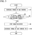
Fig. 3 is a flowchart showing a stopping method in the compressor control device in the embodiment of the present invention. -
Fig. 4 is a graph showing an example of control through the compressor control device in the embodiment of the present invention and showing variation over time in a required torque. - A compressor unit which is a rotary machine unit according to an embodiment is, for example, a unit applied to a liquefaction plant for natural gas. As shown in
Fig. 1 , acompressor unit 1 includes a compressor 10 (rotary machine), a gas turbine 20 (turbine) configured to generate a driving force as a driving source to rotate arotating shaft 13 in thecompressor 10, and an induction motor 30 (electric motor). - The
gas turbine 20 includes a turbinemain body 21 having aturbine output shaft 23 connected to the rotatingshaft 13 in thecompressor 10 and aturbine control device 22 configured to control the turbinemain body 21 to be driven at a predetermined output. Theinduction motor 30 includes an electric motormain body 31 having an electricmotor output shaft 33 connected to the rotatingshaft 13 in thecompressor 10 via a coupling and an electricmotor control device 32 configured to control the electric motormain body 31 to be driven at a predetermined output. - The
compressor 10 includes a compressormain body 11 having the rotatingshaft 13 connected tooutput shafts gas turbine 20 and theinduction motor 30 and acompressor control device 12 configured to control the compressormain body 11. - The
induction motor 30 is an auxiliary electric motor configured to assist thegas turbine 20 which drives thecompressor 10. Theinduction motor 30 includes a stator having a winding structure and a rotor. Theinduction motor 30 generates a rotating magnetic field when an alternating current (AC) voltage is applied to the stator and generates an induced electromotive force in the rotor due to the rotating magnetic field. The rotor rotates when a rotational force occurs in the same direction as the rotating magnetic field due to the interaction between a current caused by an induced electromotive force and the rotating magnetic field. - The electric
motor control device 32 includes an inverter which is a frequency conversion device configured to change a frequency of electric power to be supplied. The inverter in the embodiment has no a regeneration function (a function of returning electric power to an electric power source side). Thus, in theinduction motor 30 in the embodiment, when an output frequency of the inverter is smaller than the number of rotations of theinduction motor 30, theinduction motor 30 is in a power generation mode. Thus, the inverter trips (stops). - The electric
motor control device 32 includes a groundfault detection unit 32a configured to detect a ground fault of theinduction motor 30. - The
compressor control device 12 is connected to aplant control unit 2 configured to control the entire plant having thecompressor unit 1 installed therein. A signal of a pressure, a compression ratio, a speed, and the like of a compressed gas discharged from thecompressor 10 is input to theplant control unit 2. Thecompressor control device 12 controls the compressormain body 11 on the basis of the input from theplant control unit 2 and performs an input on theturbine control device 22 and the electricmotor control device 32. - Each output condition of the pressure, the compression ratio, the speed, and the like of the compressed gas discharged from the
compressor 10 is input from theplant control unit 2 to thecompressor control device 12 as an input signal. Thecompressor control device 12 includes a requiredoutput setting unit 12a configured to set a required torque T required to drive thecompressor 10 on the basis of the input signal and the like. - It should be noted that the required torque T is a concept which includes a target speed corresponding to each output condition of the compressed gas in the
compressor 10 based on the input signal and a torque set at a certain time in a process of increasing or decreasing the speed from a current speed to the target speed. - The
compressor control device 12 includes anoutput determination unit 12b configured to determine whether to drive theinduction motor 30 on the basis of the required torque T set by the requiredoutput setting unit 12a. - The
output determination unit 12b has a function of determining whether a torque of thegas turbine 20 has reached a lower limit T1 (refer toFig. 4 ) of a stable output range of thegas turbine 20 and a function of determining whether the required torque T is greater than a reference torque T2 set in advance. - The stable output range is an output range in which the
gas turbine 20 can stably change an output (torque). - The reference torque T2 set in the
output determination unit 12b is less than a rated torque T3 of thegas turbine 20 and is set in a high output section in the stable output range of thegas turbine 20. For example, the reference torque T2 is set to 90% of the rated torque T3 as the high output section in the stable output range of thegas turbine 20. - The reference torque T2 which is in the high output section in the stable output range of the
gas turbine 20 is set to 90% of the rated torque T3, but the stable output range of thegas turbine 20 is determined for eachgas turbine 20 and the high output section is preferably a value in which an upper limit of the stable output range or a certain margin is taken into account. - The
compressor control device 12 includes a drivesource command unit 12c configured to instruct each of theturbine control device 22 and the electricmotor control device 32 on the basis of the determination result of theoutput determination unit 12b and the required torque T and to drive the turbinemain body 21 and the electric motormain body 31. That is, the drivesource command unit 12c sets a torque of the gas turbine 20 (turbine output torque Tt) and a torque of the induction motor 30 (electric motor output torque Tm) on the basis of the determination result of theoutput determination unit 12b and the required torque T. - The drive
source command unit 12c has a function of setting theinduction motor 30 to a minimum torque Tm1 when the turbine output torque Tt is greater than or equal to the lower limit T1 of the stable output range of thegas turbine 20. That is, thecompressor control device 12 instructs the electricmotor control device 32 so that, in a case that thegas turbine 20 starts up and the turbine output torque Tt is greater than or equal to the lower limit T1 of the stable output range of thegas turbine 20, even when the set required torque T is low and it is unnecessary to add the driving force of theinduction motor 30, theinduction motor 30 is driven with a torque greater than or equal to the minimum torque Tm1. - Here, the minimum torque Tm1 of the
induction motor 30 is a minimum torque in which theinduction motor 30 can output in a stable state in a state in which theinduction motor 30 has started up. The minimum torque Tm1 of theinduction motor 30 in the embodiment is, for example, 10% of a rated torque of theinduction motor 30. - Also, the drive
source command unit 12c has a function of setting the turbine output torque Tt to a torque obtained by subtracting the electric motor output torque Tm from the required torque T. That is, the turbine output torque Tt is calculated by the following expression (1):
- Thus, even when the
induction motor 30 is driven with the minimum torque Tm1, a sum torque of thegas turbine 20 and theinduction motor 30 is maintained at the set required torque T. - An action of the
compressor unit 1 and control by thecompressor control device 12 in the embodiment will be described in detail below on the basis of the flowcharts shown inFigs. 2 and3 . - As shown in
Fig. 2 , when an operation of thecompressor unit 1 starts, the requiredoutput setting unit 12a calculates the required torque T on the basis of an input from theplant control unit 2. - In Step S1, the required
output setting unit 12a in thecompressor control device 12 changes the required torque T to increase a torque output of the gas turbine 20 (turbine torque Tt). - Subsequently, in Step S2, the
output determination unit 12b in thecompressor control device 12 determines whether the turbine output torque Tt has reached the lower limit T1 of the stable output range. When the turbine output torque Tt has not reached the lower limit of the stable output range (NO), increasing the output of thegas turbine 20 continues. - When it is determined that the turbine output torque Tt has reached the lower limit T1 of the stable output range (YES), in Step S3, the drive
source command unit 12c starts up theinduction motor 30 and sets the electric motor output torque Tm to the minimum torque Tm1. - Here, the drive
source command unit 12c sets the turbine output torque Tt to a torque obtained by subtracting the electric motor output torque Tm from the required torque T. That is, the turbine output torque Tt is reduced in correspondence with a torque increased when theinduction motor 30 is driven. Thus, even when theinduction motor 30 is driven, the set required torque T is maintained without changing the sum torque of thegas turbine 20 and theinduction motor 30. - Also, in Step S3, the ground
fault detection unit 32a in the electricmotor control device 32 enables a ground fault detection in theinduction motor 30. The groundfault detection unit 32a performs a process such as tripping theinduction motor 30 when a ground fault is detected. - Here, when power required for the
compressor 10 increases due to an increase in load on the plant, in Step S4, theplant control unit 2 increases the required torque T. - Subsequently, in Step S5, the
output determination unit 12b determines whether the required torque T is greater than the reference torque T2. Moreover, when the required torque T is lower than or equal to the reference torque T2 (YES), that is, when the required torque T is 90% or lower of the rated torque T3 of thegas turbine 20 in the embodiment, the drivesource command unit 12c instructs theturbine control device 22 to drive the turbinemain body 21 without adding the driving force of theinduction motor 30. - On the other hand, when it is determined by the
output determination unit 12b that the required torque T is greater than the reference torque T2 in Step S5 (NO), in Step S6, the drivesource command unit 12c distributes the required torque T to the turbine output torque Tt and the electric motor output torque Tm. To be specific, the turbine output torque Tt is set to be higher than or equal to the reference torque T2 and lower than or equal to the rated torque T3. Moreover, the electric motor output torque Tm is set to a value obtained by subtracting a set value of the turbine output torque Tt from the required torque T. - Subsequently, the
turbine control device 22 is instructed to drive the turbinemain body 21 in accordance with the distributed torque and the electricmotor control device 32 is also instructed to drive the electric motormain body 31 with a torque greater than the minimum torque Tm1. Thus, thecompressor 10 can operate by obtaining a driving force which is the required torque T as a whole driving source using thegas turbine 20 and theinduction motor 30, that is, can operate by obtaining a driving force greater than or equal to the rated torque T3 of thegas turbine 20. - Here, even when the required torque T is reduced due to a decrease in load on the plant and the required torque T is smaller than the reference torque T2, the drive
source command unit 12c sets the electric motor output torque Tm to the minimum torque Tm1 of theinduction motor 30. - As shown in
Fig. 3 , when stopping thecompressor unit 1, in Step S7, the requiredoutput setting unit 12a in thecompressor control device 12 changes the required torque T to decrease the turbine output torque Tt. - Subsequently, in Step S8, the
output determination unit 12b in thecompressor control device 12 determines whether the electric motor output torque Tm is greater than the minimum torque Tm1. When the electric motor output torque Tm is less than or equal to the minimum torque Tm1, in Step S9, the drivesource command unit 12c stops theinduction motor 30. - Subsequently, in Step S10, the required
output setting unit 12a reduces the required torque T until the number of rotations of thegas turbine 20 is 0 to decrease the turbine output torque Tt. -
Fig. 4 shows an example in which thegas turbine 20 and theinduction motor 30 which are driving sources of thecompressor unit 1 in the embodiment are controlled in accordance with the control procedure and the required torque T is changed in accordance with an input signal from theplant control unit 2. - As shown in
Fig. 4 , when an operation starts at time t = 0, in Step S1, thecompressor control device 12 increases the turbine output torque Tt to the lower limit T1 of the stable output range of the gas turbine 20 (Step S1). - At time t = t1, when it is determined that the turbine output torque Tt has reached the lower limit T1 of the stable output range of the
gas turbine 20, thecompressor control device 12 holds the turbine output torque Tt (Step S2). - Subsequently, at time t = t2, the
compressor control device 12 sets the electric motor output torque Tm to the minimum torque Tm1. Thus, theinduction motor 30 outputs the minimum torque Tm1 (Step S3). - Here, there is an interval between time t2 and time t1, but there is no limitation to this. The
induction motor 30 may be driven with the minimum torque Tm1 at a stage at which the turbine output torque Tt has reached the lower limit T1 of the stable output range,. - Also, at time t = t2, the drive
source command unit 12c reduces the turbine output torque Tt corresponding to the minimum torque Tm1. Thus, the required torque T does not change before and after time t = t2. - Subsequently, at time t = t5, the required torque T at each time is calculated so that a target torque T4 is provided. Moreover, the turbine output torque Tt is increased and the electric motor output torque Tm is maintained at the minimum torque Tm1 until the required torque T is greater than the reference torque T2 (Step S4).
- On the other hand, at time t = t4, when it is determined that the required torque T is greater than the reference torque T2, the required torque T is output to be distributed to the
gas turbine 20 and the induction motor 30 (Step S5 and Step S6). - Here, a first range At shows an output by the
gas turbine 20, a second range Am shows an output by theinduction motor 30, and the required torque T is output as a sum of both. - At time t = t5, the drive
source command unit 12c controls thegas turbine 20 and theinduction motor 30 so that the electric motor output torque Tm reaches a rated torque Tm2 at the same time that a torque of thegas turbine 20 reaches the rated torque T3. - It should be noted that the control method is not limited to this and a time at which the turbine output torque Tt reaches the rated torque T3 may be different from a time at which the electric motor output torque Tm reaches the rated torque Tm2.
- Also, when an output supplied to the
compressor 10 at time t = t5 reaches a target torque T4 determined on the basis of an input signal from theplant control unit 2, the required torque T is kept constant and a normal operation is performed. - As described above, when the
induction motor 30 is driven if necessary using the reference torque T2 as a reference and when the required torque T is less than or equal to the reference torque T2, thegas turbine 20 can independently efficiently provide a driving force and thecompressor 10 can operate. - Also, the reference torque T2 serving as a reference for starting driving of the
induction motor 30 is set to 90% of the rated torque T3 which is the high output section in the stable output range of thegas turbine 20 in advance. For this reason, when the driving of theinduction motor 30 is started, it is unnecessary to synchronize theinduction motor 30 with thegas turbine 20 in an unstable state in the vicinity of the rated torque T3 of thegas turbine 20 and it is also unnecessary to decrease an already set turbine output torque Tt to restore the turbine output torque Tt to a stable state. That is, when an output of the turbine output torque Tt is increased by setting the reference torque T2 in a stable range, for example, 90% of the rated torque T3, thecompressor 10 can operate by allowing a smooth transition from an output by theindependent gas turbine 20 to an output by thegas turbine 20 and theinduction motor 30. - On the other hand, at time t = t6, when a command is input from the
plant control unit 2 to decrease a pressure of a compressed gas using thecompressor 10, the required torque T is calculated at each time so that the turbine output torque Tt and the electric motor output torque Tm decrease (Step S7). - At time t = t8, the turbine output torque Tt is decreased until the turbine output torque Tt reaches the lower limit T1 of the stable output range of the
gas turbine 20. At that time, when the electric motor output torque Tm has decreased to the minimum torque Tm1, theinduction motor 30 is stopped (Step S8 and Step S9). - As described above, according to the
compressor unit 1 and thecompressor control device 12 installed in thecompressor unit 1 in the embodiment, since theoutput determination unit 12b and the drivesource command unit 12c are provided, it is possible to operate thecompressor 10 stably and efficiently with a desired output. - Particularly, in the embodiment, a ground fault detection in the
induction motor 30 becomes possible by setting theinduction motor 30 to the minimum torque Tm1 or higher when the turbine output torque Tt is at least greater than or equal to the lower limit T2 in the stable output range of thegas turbine 20. Furthermore, it is possible to reduce a difference between the required torque T and an actual sum torque of thegas turbine 20 and theinduction motor 30 by setting the turbine output torque Tt to a torque obtained by subtracting the electric motor output torque Tm from the required torque T. - Also, the reference torque T2 to start driving of the
induction motor 30 is set in the stable output range of thegas turbine 20 in advance and it is unnecessary to synchronize theinduction motor 30 with thegas turbine 20 in an unstable state in the vicinity of a rated output of thegas turbine 20 when the driving of theinduction motor 30 is started. That is, thecompressor 10 can operate by allowing a smooth transition from an output by the independent gas turbine to an output by thegas turbine 20 and theinduction motor 30 and it is possible to omit waste of falling and raising the turbine output torque Tt once as in the related art. - Also, by adopting the
induction motor 30 as an electric motor, for example, it is possible to reduce the manufacturing costs as compared with a DC electric motor. - By adopting an inverter having no regeneration function as an inverter of the electric
motor control device 32, the manufacturing costs can be reduced. - Although the embodiment of the present invention has been described in detail above with reference to the drawings, a specific configuration is not limited to the embodiment and includes changes in design and the like without departing from the scope of the present invention.
- For example, a configuration is provided so that the required torque T exceeds the reference torque T2 and then an output of the
gas turbine 20 is increased to the rated torque T3 and each output of thegas turbine 20 and theinduction motor 30 is distributed in the above-described embodiment, but the present invention is not limited thereto. That is, after the required torque T exceeds the reference torque T2, the output of thegas turbine 20 may be kept constant at the reference torque T2 and the increasing of the required torque T after that may be output from theinduction motor 30. - Also, the
gas turbine 20 is assumed to be a turbine configured to operate thecompressor 10 in thecompressor unit 1 in each embodiment, but the present invention is not limited thereto. For example, a steam turbine may be adopted. Furthermore, each control device of thecompressor 10, thegas turbine 20, and theinduction motor 30 is assumed to be independent, but the present invention is not limited thereto. They may be configured as an integral control device. Moreover, thecompressor control device 12 controls thecompressor 10 on the basis of the command from the externalplant control unit 2 and instructs thegas turbine 20 and theinduction motor 30, but the present invention is not limited thereto. For example, thecompressor control device 12 may include an operation part and perform control independently from the outside on the basis of an input through the operation part. -
- 1
- Compressor unit
- 2
- Plant control unit
- 10
- Compressor
- 11
- Compressor main body
- 12
- Compressor control device
- 12a
- Required output setting unit
- 12b
- Output determination unit
- 12c
- Drive source command unit
- 13
- Rotating shaft
- 20
- Gas turbine
- 21
- Turbine main body
- 22
- Turbine control device
- 23
- Turbine output shaft
- 30
- Induction motor
- 31
- Electric motor main body
- 32
- Electric motor control device
- 32a
- Ground fault detection unit
- 33
- Electric motor output shaft
- T
- Required torque
- T1
- Lower limit of stable output range
- T2
- Reference torque
- Tm
- Electric motor output torque
- Tt
- Turbine output torque
Claims (5)
- A control device for a rotary machine (10) which is driven by a turbine output torque which is an output of a turbine (20) and an electric motor output torque which is an output of an induction motor (30), the control device comprising:a required output setting unit (12a) configured to set a required torque (T) for driving the rotary machine (10);an output determination unit (12b) configured to determine whether the turbine output torque of the turbine (20) has reached a lower limit (T1) of a stable output range of the turbine (20); anda drive source command unit (12c) configured to drive the turbine (20) and the induction motor (30),wherein when, while the turbine output torque is increasing, the output determination unit (12b) determines that the turbine output torque (Tt) has reached the lower limit (T1) of the stable output range of the turbine, the drive source command unit (12c) starts up the induction motor (30) and sets the electric motor output torque (Tm) to a minimum torque (Tm1) or higher, in which the induction motor (30) is capable of outputting in a stable state, and the drive source command unit (12c) sets the turbine output torque (Tt) to a value obtained by subtracting the electric motor output torque (Tm) from the required torque (T).
- The control device for a rotary machine according to claim 1,
wherein the output determination unit (12b) is configured to determine whether the required torque (T) is greater than a reference torque set in advance in the stable output range of the turbine (20), and
wherein the drive source command unit (12c) sets a torque of the induction motor (30) to a value greater than the minimum torque when it is determined by the output determination unit that the required torque is greater than the reference torque. - A rotary machine unit, comprising:a turbine (20) and an induction motor (30) as driving sources;a rotary machine (10) connected to the turbine (20) and the induction motor (30); andthe control device for a rotary machine according to claim 1 or 2.
- A control method for a rotary machine (10) which is driven by a turbine output torque which is an output of a turbine (20) and an electric motor output torque which is an output of an induction motor (30), the control method comprising:a step of setting a required torque (T) for driving the rotary machine (10); a step of increasing the turbine output torque (Tt);a step of determining whether the turbine output torque (Tt) of the turbine (20) has reached a lower limit (T1) of a stable output range of the turbine (20); anda step of starting up the induction motor (30) and setting the electric motor output torque (Tm) to a minimum torque (Tm1) or higher, in which the induction motor (30) is capable of outputting in a stable state, and setting the turbine output torque to a value obtained by subtracting the electric motor output (Tm) torque from the required torque (T) when the turbine output torque has reached the lower limit (T1) of the stable output range of the turbine.
- The control method for a rotary machine according to claim 4, further comprising:a step of determining whether the required torque (T) is greater than a reference torque set in advance in the stable output range of the turbine; anda step of setting a torque of the induction motor to a value greater than the minimum torque when it is determined that the required torque is greater than the reference torque.
Applications Claiming Priority (1)
| Application Number | Priority Date | Filing Date | Title |
|---|---|---|---|
| PCT/JP2016/078390 WO2018061076A1 (en) | 2016-09-27 | 2016-09-27 | Control device and control method for rotary machine, and rotary machine unit equipped with control device |
Publications (3)
| Publication Number | Publication Date |
|---|---|
| EP3498985A1 EP3498985A1 (en) | 2019-06-19 |
| EP3498985A4 EP3498985A4 (en) | 2019-09-25 |
| EP3498985B1 true EP3498985B1 (en) | 2020-09-09 |
Family
ID=61760227
Family Applications (1)
| Application Number | Title | Priority Date | Filing Date |
|---|---|---|---|
| EP16917629.4A Active EP3498985B1 (en) | 2016-09-27 | 2016-09-27 | Control device and control method for rotary machine, and rotary machine unit equipped with control device |
Country Status (4)
| Country | Link |
|---|---|
| US (1) | US11105270B2 (en) |
| EP (1) | EP3498985B1 (en) |
| JP (1) | JP6802282B2 (en) |
| WO (1) | WO2018061076A1 (en) |
Families Citing this family (2)
| Publication number | Priority date | Publication date | Assignee | Title |
|---|---|---|---|---|
| CN112483450B (en) * | 2020-11-12 | 2022-06-03 | 福建凯威消防通风设备有限公司 | Early warning method of emergency fan with early warning function |
| IT202300016857A1 (en) * | 2023-08-07 | 2025-02-07 | Nuovo Pignone Tecnologie Srl | METHOD FOR MONITORING AND CONTROLLING A HYBRID TRAIN PROPULSION SYSTEM |
Family Cites Families (14)
| Publication number | Priority date | Publication date | Assignee | Title |
|---|---|---|---|---|
| JPS5851122B2 (en) | 1976-04-13 | 1983-11-15 | 株式会社荏原製作所 | Drive machine control method and device |
| JPS54158627A (en) * | 1978-06-05 | 1979-12-14 | Toshiba Corp | Controlling for motor and device thereof |
| DE3669427D1 (en) * | 1985-12-24 | 1990-04-12 | Toshiba Kawasaki Kk | AUXILIARY DRIVE FOR A TURBINE. |
| US4771606A (en) | 1986-08-25 | 1988-09-20 | Kabushiki Kaisha Toshiba | Helper drive apparatus for turbine drive system |
| JP2509587B2 (en) | 1986-11-11 | 1996-06-19 | 株式会社東芝 | Helper motor system |
| JPH0744867B2 (en) | 1986-11-14 | 1995-05-15 | 株式会社東芝 | Turbin helper drive |
| DE3782613T2 (en) | 1986-11-14 | 1993-03-25 | Toshiba Kawasaki Kk | AUXILIARY DRIVE FOR A TURBINE. |
| US5391925A (en) * | 1993-09-10 | 1995-02-21 | Trigen Energy Corporation | Prime mover driven compressor/chiller with motor on common shaft for large cooling systems |
| KR100275375B1 (en) * | 1997-11-10 | 2000-12-15 | 이중구 | Method for controlling gas turbine |
| US8695321B2 (en) * | 2007-12-27 | 2014-04-15 | Mitsubishi Heavy Industries, Ltd. | Gas turbine control apparatus and control method for generating an electric motor torque instruction based on the detected exhaust gas temperature |
| JP5324140B2 (en) | 2008-06-19 | 2013-10-23 | 三菱重工コンプレッサ株式会社 | Rotating machine control device and control method, and rotating machine unit provided with control device |
| JP5167078B2 (en) | 2008-11-12 | 2013-03-21 | 三菱重工業株式会社 | Compressor drive unit and operation method |
| US8344673B2 (en) * | 2008-12-04 | 2013-01-01 | Nuovo Pignone S.P.A. | Torsional mode damping apparatus |
| US11319963B2 (en) * | 2018-05-30 | 2022-05-03 | Raytheon Technologies Corporation | Compressor surge control |
-
2016
- 2016-09-27 WO PCT/JP2016/078390 patent/WO2018061076A1/en not_active Ceased
- 2016-09-27 EP EP16917629.4A patent/EP3498985B1/en active Active
- 2016-09-27 JP JP2018541746A patent/JP6802282B2/en active Active
- 2016-09-27 US US16/333,010 patent/US11105270B2/en active Active
Non-Patent Citations (1)
| Title |
|---|
| None * |
Also Published As
| Publication number | Publication date |
|---|---|
| US11105270B2 (en) | 2021-08-31 |
| JP6802282B2 (en) | 2020-12-16 |
| EP3498985A1 (en) | 2019-06-19 |
| US20190264692A1 (en) | 2019-08-29 |
| WO2018061076A1 (en) | 2018-04-05 |
| JPWO2018061076A1 (en) | 2019-06-24 |
| EP3498985A4 (en) | 2019-09-25 |
Similar Documents
| Publication | Publication Date | Title |
|---|---|---|
| KR101509868B1 (en) | Fail-safe method and apparatus for a high voltage parts in hybrrid electric vehicle | |
| EP2020745A2 (en) | Engine start system with a regulated permanent magnet machine | |
| US9923431B2 (en) | Variable speed drive arrangement | |
| US10090790B2 (en) | Motor control device | |
| US20240337221A1 (en) | Electricity generation system and aircraft | |
| EP3498985B1 (en) | Control device and control method for rotary machine, and rotary machine unit equipped with control device | |
| JP6809247B2 (en) | Frequency conversion system controller | |
| US11114957B2 (en) | Vacuum pump and motor controller | |
| KR101307024B1 (en) | A control method for sensorless permanent magnet synchronous motor | |
| JP6013073B2 (en) | Electric motor drive device and operation method thereof | |
| CN108540039B (en) | Inverter control apparatus | |
| JP2002233181A (en) | Motor control device | |
| Hu et al. | Strategy for restarting the free-running induction motor driven by a high-voltage inverter based on V/f fuzzy control | |
| JP2011050244A (en) | Method and device for driving compressor | |
| KR20200017500A (en) | Thyristor starter | |
| JP4517775B2 (en) | Control method of flywheel type uninterruptible power supply and uninterruptible power supply using the same | |
| JP4706661B2 (en) | Compressor driving method and apparatus | |
| JP5324140B2 (en) | Rotating machine control device and control method, and rotating machine unit provided with control device | |
| JP2017130987A (en) | Synchronous machine rotor excitation system | |
| JP5003437B2 (en) | Flywheel uninterruptible power supply | |
| JP6357649B2 (en) | DC motor drive device and ceiling-embedded ventilator equipped with the same | |
| JP2006087154A (en) | Inverter drive blower controller | |
| EP2595309A1 (en) | Systems and methods involving electrical start and power generation | |
| JP2016031045A (en) | Emergency power supply system of gas turbine power generation plant | |
| JP2005045973A (en) | Voltage source inverter device |
Legal Events
| Date | Code | Title | Description |
|---|---|---|---|
| STAA | Information on the status of an ep patent application or granted ep patent |
Free format text: STATUS: THE INTERNATIONAL PUBLICATION HAS BEEN MADE |
|
| PUAI | Public reference made under article 153(3) epc to a published international application that has entered the european phase |
Free format text: ORIGINAL CODE: 0009012 |
|
| STAA | Information on the status of an ep patent application or granted ep patent |
Free format text: STATUS: REQUEST FOR EXAMINATION WAS MADE |
|
| 17P | Request for examination filed |
Effective date: 20190312 |
|
| AK | Designated contracting states |
Kind code of ref document: A1 Designated state(s): AL AT BE BG CH CY CZ DE DK EE ES FI FR GB GR HR HU IE IS IT LI LT LU LV MC MK MT NL NO PL PT RO RS SE SI SK SM TR |
|
| AX | Request for extension of the european patent |
Extension state: BA ME |
|
| A4 | Supplementary search report drawn up and despatched |
Effective date: 20190822 |
|
| RIC1 | Information provided on ipc code assigned before grant |
Ipc: F01D 15/08 20060101ALI20190816BHEP Ipc: F04D 27/00 20060101ALI20190816BHEP Ipc: H02P 29/00 20160101ALI20190816BHEP Ipc: F02C 6/00 20060101ALI20190816BHEP Ipc: F25J 1/02 20060101ALI20190816BHEP Ipc: F04D 25/04 20060101ALI20190816BHEP Ipc: F04D 27/02 20060101ALI20190816BHEP Ipc: F01D 15/10 20060101AFI20190816BHEP Ipc: F02C 9/00 20060101ALI20190816BHEP Ipc: H02P 23/00 20160101ALI20190816BHEP Ipc: F04D 25/06 20060101ALI20190816BHEP Ipc: F04D 25/02 20060101ALI20190816BHEP |
|
| DAV | Request for validation of the european patent (deleted) | ||
| DAX | Request for extension of the european patent (deleted) | ||
| GRAP | Despatch of communication of intention to grant a patent |
Free format text: ORIGINAL CODE: EPIDOSNIGR1 |
|
| STAA | Information on the status of an ep patent application or granted ep patent |
Free format text: STATUS: GRANT OF PATENT IS INTENDED |
|
| INTG | Intention to grant announced |
Effective date: 20200416 |
|
| GRAS | Grant fee paid |
Free format text: ORIGINAL CODE: EPIDOSNIGR3 |
|
| GRAA | (expected) grant |
Free format text: ORIGINAL CODE: 0009210 |
|
| STAA | Information on the status of an ep patent application or granted ep patent |
Free format text: STATUS: THE PATENT HAS BEEN GRANTED |
|
| AK | Designated contracting states |
Kind code of ref document: B1 Designated state(s): AL AT BE BG CH CY CZ DE DK EE ES FI FR GB GR HR HU IE IS IT LI LT LU LV MC MK MT NL NO PL PT RO RS SE SI SK SM TR |
|
| REG | Reference to a national code |
Ref country code: GB Ref legal event code: FG4D |
|
| REG | Reference to a national code |
Ref country code: AT Ref legal event code: REF Ref document number: 1311817 Country of ref document: AT Kind code of ref document: T Effective date: 20200915 Ref country code: CH Ref legal event code: EP |
|
| REG | Reference to a national code |
Ref country code: DE Ref legal event code: R096 Ref document number: 602016043948 Country of ref document: DE |
|
| REG | Reference to a national code |
Ref country code: IE Ref legal event code: FG4D |
|
| REG | Reference to a national code |
Ref country code: LT Ref legal event code: MG4D |
|
| PG25 | Lapsed in a contracting state [announced via postgrant information from national office to epo] |
Ref country code: LT Free format text: LAPSE BECAUSE OF FAILURE TO SUBMIT A TRANSLATION OF THE DESCRIPTION OR TO PAY THE FEE WITHIN THE PRESCRIBED TIME-LIMIT Effective date: 20200909 Ref country code: HR Free format text: LAPSE BECAUSE OF FAILURE TO SUBMIT A TRANSLATION OF THE DESCRIPTION OR TO PAY THE FEE WITHIN THE PRESCRIBED TIME-LIMIT Effective date: 20200909 Ref country code: BG Free format text: LAPSE BECAUSE OF FAILURE TO SUBMIT A TRANSLATION OF THE DESCRIPTION OR TO PAY THE FEE WITHIN THE PRESCRIBED TIME-LIMIT Effective date: 20201209 Ref country code: SE Free format text: LAPSE BECAUSE OF FAILURE TO SUBMIT A TRANSLATION OF THE DESCRIPTION OR TO PAY THE FEE WITHIN THE PRESCRIBED TIME-LIMIT Effective date: 20200909 Ref country code: GR Free format text: LAPSE BECAUSE OF FAILURE TO SUBMIT A TRANSLATION OF THE DESCRIPTION OR TO PAY THE FEE WITHIN THE PRESCRIBED TIME-LIMIT Effective date: 20201210 Ref country code: NO Free format text: LAPSE BECAUSE OF FAILURE TO SUBMIT A TRANSLATION OF THE DESCRIPTION OR TO PAY THE FEE WITHIN THE PRESCRIBED TIME-LIMIT Effective date: 20201209 Ref country code: FI Free format text: LAPSE BECAUSE OF FAILURE TO SUBMIT A TRANSLATION OF THE DESCRIPTION OR TO PAY THE FEE WITHIN THE PRESCRIBED TIME-LIMIT Effective date: 20200909 |
|
| REG | Reference to a national code |
Ref country code: AT Ref legal event code: MK05 Ref document number: 1311817 Country of ref document: AT Kind code of ref document: T Effective date: 20200909 |
|
| REG | Reference to a national code |
Ref country code: NL Ref legal event code: MP Effective date: 20200909 |
|
| PG25 | Lapsed in a contracting state [announced via postgrant information from national office to epo] |
Ref country code: RS Free format text: LAPSE BECAUSE OF FAILURE TO SUBMIT A TRANSLATION OF THE DESCRIPTION OR TO PAY THE FEE WITHIN THE PRESCRIBED TIME-LIMIT Effective date: 20200909 Ref country code: LV Free format text: LAPSE BECAUSE OF FAILURE TO SUBMIT A TRANSLATION OF THE DESCRIPTION OR TO PAY THE FEE WITHIN THE PRESCRIBED TIME-LIMIT Effective date: 20200909 Ref country code: PL Free format text: LAPSE BECAUSE OF FAILURE TO SUBMIT A TRANSLATION OF THE DESCRIPTION OR TO PAY THE FEE WITHIN THE PRESCRIBED TIME-LIMIT Effective date: 20200909 |
|
| PG25 | Lapsed in a contracting state [announced via postgrant information from national office to epo] |
Ref country code: RO Free format text: LAPSE BECAUSE OF FAILURE TO SUBMIT A TRANSLATION OF THE DESCRIPTION OR TO PAY THE FEE WITHIN THE PRESCRIBED TIME-LIMIT Effective date: 20200909 Ref country code: PT Free format text: LAPSE BECAUSE OF FAILURE TO SUBMIT A TRANSLATION OF THE DESCRIPTION OR TO PAY THE FEE WITHIN THE PRESCRIBED TIME-LIMIT Effective date: 20210111 Ref country code: CZ Free format text: LAPSE BECAUSE OF FAILURE TO SUBMIT A TRANSLATION OF THE DESCRIPTION OR TO PAY THE FEE WITHIN THE PRESCRIBED TIME-LIMIT Effective date: 20200909 Ref country code: EE Free format text: LAPSE BECAUSE OF FAILURE TO SUBMIT A TRANSLATION OF THE DESCRIPTION OR TO PAY THE FEE WITHIN THE PRESCRIBED TIME-LIMIT Effective date: 20200909 Ref country code: SM Free format text: LAPSE BECAUSE OF FAILURE TO SUBMIT A TRANSLATION OF THE DESCRIPTION OR TO PAY THE FEE WITHIN THE PRESCRIBED TIME-LIMIT Effective date: 20200909 |
|
| REG | Reference to a national code |
Ref country code: CH Ref legal event code: PL |
|
| PG25 | Lapsed in a contracting state [announced via postgrant information from national office to epo] |
Ref country code: IS Free format text: LAPSE BECAUSE OF FAILURE TO SUBMIT A TRANSLATION OF THE DESCRIPTION OR TO PAY THE FEE WITHIN THE PRESCRIBED TIME-LIMIT Effective date: 20210109 Ref country code: AL Free format text: LAPSE BECAUSE OF FAILURE TO SUBMIT A TRANSLATION OF THE DESCRIPTION OR TO PAY THE FEE WITHIN THE PRESCRIBED TIME-LIMIT Effective date: 20200909 Ref country code: AT Free format text: LAPSE BECAUSE OF FAILURE TO SUBMIT A TRANSLATION OF THE DESCRIPTION OR TO PAY THE FEE WITHIN THE PRESCRIBED TIME-LIMIT Effective date: 20200909 Ref country code: ES Free format text: LAPSE BECAUSE OF FAILURE TO SUBMIT A TRANSLATION OF THE DESCRIPTION OR TO PAY THE FEE WITHIN THE PRESCRIBED TIME-LIMIT Effective date: 20200909 |
|
| REG | Reference to a national code |
Ref country code: DE Ref legal event code: R097 Ref document number: 602016043948 Country of ref document: DE |
|
| REG | Reference to a national code |
Ref country code: BE Ref legal event code: MM Effective date: 20200930 |
|
| PG25 | Lapsed in a contracting state [announced via postgrant information from national office to epo] |
Ref country code: MC Free format text: LAPSE BECAUSE OF FAILURE TO SUBMIT A TRANSLATION OF THE DESCRIPTION OR TO PAY THE FEE WITHIN THE PRESCRIBED TIME-LIMIT Effective date: 20200909 Ref country code: SK Free format text: LAPSE BECAUSE OF FAILURE TO SUBMIT A TRANSLATION OF THE DESCRIPTION OR TO PAY THE FEE WITHIN THE PRESCRIBED TIME-LIMIT Effective date: 20200909 Ref country code: LU Free format text: LAPSE BECAUSE OF NON-PAYMENT OF DUE FEES Effective date: 20200927 |
|
| PLBE | No opposition filed within time limit |
Free format text: ORIGINAL CODE: 0009261 |
|
| STAA | Information on the status of an ep patent application or granted ep patent |
Free format text: STATUS: NO OPPOSITION FILED WITHIN TIME LIMIT |
|
| 26N | No opposition filed |
Effective date: 20210610 |
|
| GBPC | Gb: european patent ceased through non-payment of renewal fee |
Effective date: 20201209 |
|
| PG25 | Lapsed in a contracting state [announced via postgrant information from national office to epo] |
Ref country code: LI Free format text: LAPSE BECAUSE OF NON-PAYMENT OF DUE FEES Effective date: 20200930 Ref country code: IE Free format text: LAPSE BECAUSE OF NON-PAYMENT OF DUE FEES Effective date: 20200927 Ref country code: DK Free format text: LAPSE BECAUSE OF FAILURE TO SUBMIT A TRANSLATION OF THE DESCRIPTION OR TO PAY THE FEE WITHIN THE PRESCRIBED TIME-LIMIT Effective date: 20200909 Ref country code: SI Free format text: LAPSE BECAUSE OF FAILURE TO SUBMIT A TRANSLATION OF THE DESCRIPTION OR TO PAY THE FEE WITHIN THE PRESCRIBED TIME-LIMIT Effective date: 20200909 Ref country code: CH Free format text: LAPSE BECAUSE OF NON-PAYMENT OF DUE FEES Effective date: 20200930 Ref country code: BE Free format text: LAPSE BECAUSE OF NON-PAYMENT OF DUE FEES Effective date: 20200930 |
|
| PG25 | Lapsed in a contracting state [announced via postgrant information from national office to epo] |
Ref country code: IT Free format text: LAPSE BECAUSE OF FAILURE TO SUBMIT A TRANSLATION OF THE DESCRIPTION OR TO PAY THE FEE WITHIN THE PRESCRIBED TIME-LIMIT Effective date: 20200909 Ref country code: FR Free format text: LAPSE BECAUSE OF NON-PAYMENT OF DUE FEES Effective date: 20201109 |
|
| PG25 | Lapsed in a contracting state [announced via postgrant information from national office to epo] |
Ref country code: GB Free format text: LAPSE BECAUSE OF NON-PAYMENT OF DUE FEES Effective date: 20201209 |
|
| PG25 | Lapsed in a contracting state [announced via postgrant information from national office to epo] |
Ref country code: IS Free format text: LAPSE BECAUSE OF FAILURE TO SUBMIT A TRANSLATION OF THE DESCRIPTION OR TO PAY THE FEE WITHIN THE PRESCRIBED TIME-LIMIT Effective date: 20210109 Ref country code: TR Free format text: LAPSE BECAUSE OF FAILURE TO SUBMIT A TRANSLATION OF THE DESCRIPTION OR TO PAY THE FEE WITHIN THE PRESCRIBED TIME-LIMIT Effective date: 20200909 Ref country code: MT Free format text: LAPSE BECAUSE OF FAILURE TO SUBMIT A TRANSLATION OF THE DESCRIPTION OR TO PAY THE FEE WITHIN THE PRESCRIBED TIME-LIMIT Effective date: 20200909 Ref country code: CY Free format text: LAPSE BECAUSE OF FAILURE TO SUBMIT A TRANSLATION OF THE DESCRIPTION OR TO PAY THE FEE WITHIN THE PRESCRIBED TIME-LIMIT Effective date: 20200909 |
|
| PG25 | Lapsed in a contracting state [announced via postgrant information from national office to epo] |
Ref country code: MK Free format text: LAPSE BECAUSE OF FAILURE TO SUBMIT A TRANSLATION OF THE DESCRIPTION OR TO PAY THE FEE WITHIN THE PRESCRIBED TIME-LIMIT Effective date: 20200909 |
|
| PG25 | Lapsed in a contracting state [announced via postgrant information from national office to epo] |
Ref country code: NL Free format text: LAPSE BECAUSE OF NON-PAYMENT OF DUE FEES Effective date: 20200923 |
|
| PGFP | Annual fee paid to national office [announced via postgrant information from national office to epo] |
Ref country code: DE Payment date: 20250805 Year of fee payment: 10 |