EP3498933B1 - System for mounting a plurality of panels - Google Patents
System for mounting a plurality of panels Download PDFInfo
- Publication number
- EP3498933B1 EP3498933B1 EP18211383.7A EP18211383A EP3498933B1 EP 3498933 B1 EP3498933 B1 EP 3498933B1 EP 18211383 A EP18211383 A EP 18211383A EP 3498933 B1 EP3498933 B1 EP 3498933B1
- Authority
- EP
- European Patent Office
- Prior art keywords
- locking strip
- carrier part
- carrier
- locking
- panels
- Prior art date
- Legal status (The legal status is an assumption and is not a legal conclusion. Google has not performed a legal analysis and makes no representation as to the accuracy of the status listed.)
- Active
Links
Images









Classifications
-
- E—FIXED CONSTRUCTIONS
- E04—BUILDING
- E04B—GENERAL BUILDING CONSTRUCTIONS; WALLS, e.g. PARTITIONS; ROOFS; FLOORS; CEILINGS; INSULATION OR OTHER PROTECTION OF BUILDINGS
- E04B9/00—Ceilings; Construction of ceilings, e.g. false ceilings; Ceiling construction with regard to insulation
- E04B9/34—Grid-like or open-work ceilings, e.g. lattice type box-like modules, acoustic baffles
- E04B9/36—Grid-like or open-work ceilings, e.g. lattice type box-like modules, acoustic baffles consisting of parallel slats
- E04B9/366—Grid-like or open-work ceilings, e.g. lattice type box-like modules, acoustic baffles consisting of parallel slats the principal plane of the slats being vertical
-
- E—FIXED CONSTRUCTIONS
- E04—BUILDING
- E04B—GENERAL BUILDING CONSTRUCTIONS; WALLS, e.g. PARTITIONS; ROOFS; FLOORS; CEILINGS; INSULATION OR OTHER PROTECTION OF BUILDINGS
- E04B9/00—Ceilings; Construction of ceilings, e.g. false ceilings; Ceiling construction with regard to insulation
- E04B9/22—Connection of slabs, panels, sheets or the like to the supporting construction
- E04B9/24—Connection of slabs, panels, sheets or the like to the supporting construction with the slabs, panels, sheets or the like positioned on the upperside of, or held against the underside of the horizontal flanges of the supporting construction or accessory means connected thereto
- E04B9/26—Connection of slabs, panels, sheets or the like to the supporting construction with the slabs, panels, sheets or the like positioned on the upperside of, or held against the underside of the horizontal flanges of the supporting construction or accessory means connected thereto by means of snap action of elastically deformable elements held against the underside of the supporting construction
-
- E—FIXED CONSTRUCTIONS
- E04—BUILDING
- E04B—GENERAL BUILDING CONSTRUCTIONS; WALLS, e.g. PARTITIONS; ROOFS; FLOORS; CEILINGS; INSULATION OR OTHER PROTECTION OF BUILDINGS
- E04B1/00—Constructions in general; Structures which are not restricted either to walls, e.g. partitions, or floors or ceilings or roofs
- E04B1/38—Connections for building structures in general
-
- E—FIXED CONSTRUCTIONS
- E04—BUILDING
- E04B—GENERAL BUILDING CONSTRUCTIONS; WALLS, e.g. PARTITIONS; ROOFS; FLOORS; CEILINGS; INSULATION OR OTHER PROTECTION OF BUILDINGS
- E04B2/00—Walls, e.g. partitions, for buildings; Wall construction with regard to insulation; Connections specially adapted to walls
- E04B2/88—Curtain walls
-
- E—FIXED CONSTRUCTIONS
- E04—BUILDING
- E04B—GENERAL BUILDING CONSTRUCTIONS; WALLS, e.g. PARTITIONS; ROOFS; FLOORS; CEILINGS; INSULATION OR OTHER PROTECTION OF BUILDINGS
- E04B9/00—Ceilings; Construction of ceilings, e.g. false ceilings; Ceiling construction with regard to insulation
- E04B9/06—Ceilings; Construction of ceilings, e.g. false ceilings; Ceiling construction with regard to insulation characterised by constructional features of the supporting construction, e.g. cross section or material of framework members
-
- E—FIXED CONSTRUCTIONS
- E04—BUILDING
- E04B—GENERAL BUILDING CONSTRUCTIONS; WALLS, e.g. PARTITIONS; ROOFS; FLOORS; CEILINGS; INSULATION OR OTHER PROTECTION OF BUILDINGS
- E04B9/00—Ceilings; Construction of ceilings, e.g. false ceilings; Ceiling construction with regard to insulation
- E04B9/22—Connection of slabs, panels, sheets or the like to the supporting construction
- E04B9/24—Connection of slabs, panels, sheets or the like to the supporting construction with the slabs, panels, sheets or the like positioned on the upperside of, or held against the underside of the horizontal flanges of the supporting construction or accessory means connected thereto
-
- E—FIXED CONSTRUCTIONS
- E04—BUILDING
- E04B—GENERAL BUILDING CONSTRUCTIONS; WALLS, e.g. PARTITIONS; ROOFS; FLOORS; CEILINGS; INSULATION OR OTHER PROTECTION OF BUILDINGS
- E04B9/00—Ceilings; Construction of ceilings, e.g. false ceilings; Ceiling construction with regard to insulation
- E04B9/34—Grid-like or open-work ceilings, e.g. lattice type box-like modules, acoustic baffles
- E04B9/36—Grid-like or open-work ceilings, e.g. lattice type box-like modules, acoustic baffles consisting of parallel slats
-
- E—FIXED CONSTRUCTIONS
- E04—BUILDING
- E04F—FINISHING WORK ON BUILDINGS, e.g. STAIRS, FLOORS
- E04F13/00—Coverings or linings, e.g. for walls or ceilings
- E04F13/07—Coverings or linings, e.g. for walls or ceilings composed of covering or lining elements; Sub-structures therefor; Fastening means therefor
- E04F13/08—Coverings or linings, e.g. for walls or ceilings composed of covering or lining elements; Sub-structures therefor; Fastening means therefor composed of a plurality of similar covering or lining elements
- E04F13/0801—Separate fastening elements
- E04F13/0803—Separate fastening elements with load-supporting elongated furring elements between wall and covering elements
-
- E—FIXED CONSTRUCTIONS
- E04—BUILDING
- E04F—FINISHING WORK ON BUILDINGS, e.g. STAIRS, FLOORS
- E04F13/00—Coverings or linings, e.g. for walls or ceilings
- E04F13/07—Coverings or linings, e.g. for walls or ceilings composed of covering or lining elements; Sub-structures therefor; Fastening means therefor
- E04F13/08—Coverings or linings, e.g. for walls or ceilings composed of covering or lining elements; Sub-structures therefor; Fastening means therefor composed of a plurality of similar covering or lining elements
- E04F13/0801—Separate fastening elements
- E04F13/0803—Separate fastening elements with load-supporting elongated furring elements between wall and covering elements
- E04F13/081—Separate fastening elements with load-supporting elongated furring elements between wall and covering elements with additional fastening elements between furring elements and covering elements
- E04F13/0814—Separate fastening elements with load-supporting elongated furring elements between wall and covering elements with additional fastening elements between furring elements and covering elements fixed by means of clamping action
-
- E—FIXED CONSTRUCTIONS
- E04—BUILDING
- E04F—FINISHING WORK ON BUILDINGS, e.g. STAIRS, FLOORS
- E04F13/00—Coverings or linings, e.g. for walls or ceilings
- E04F13/07—Coverings or linings, e.g. for walls or ceilings composed of covering or lining elements; Sub-structures therefor; Fastening means therefor
- E04F13/08—Coverings or linings, e.g. for walls or ceilings composed of covering or lining elements; Sub-structures therefor; Fastening means therefor composed of a plurality of similar covering or lining elements
- E04F13/0801—Separate fastening elements
- E04F13/0803—Separate fastening elements with load-supporting elongated furring elements between wall and covering elements
- E04F13/081—Separate fastening elements with load-supporting elongated furring elements between wall and covering elements with additional fastening elements between furring elements and covering elements
- E04F13/0816—Separate fastening elements with load-supporting elongated furring elements between wall and covering elements with additional fastening elements between furring elements and covering elements the additional fastening elements extending into the back side of the covering elements
- E04F13/0819—Separate fastening elements with load-supporting elongated furring elements between wall and covering elements with additional fastening elements between furring elements and covering elements the additional fastening elements extending into the back side of the covering elements inserted into grooves in the back side of the covering elements
-
- E—FIXED CONSTRUCTIONS
- E04—BUILDING
- E04F—FINISHING WORK ON BUILDINGS, e.g. STAIRS, FLOORS
- E04F13/00—Coverings or linings, e.g. for walls or ceilings
- E04F13/07—Coverings or linings, e.g. for walls or ceilings composed of covering or lining elements; Sub-structures therefor; Fastening means therefor
- E04F13/08—Coverings or linings, e.g. for walls or ceilings composed of covering or lining elements; Sub-structures therefor; Fastening means therefor composed of a plurality of similar covering or lining elements
- E04F13/0801—Separate fastening elements
- E04F13/0803—Separate fastening elements with load-supporting elongated furring elements between wall and covering elements
- E04F13/081—Separate fastening elements with load-supporting elongated furring elements between wall and covering elements with additional fastening elements between furring elements and covering elements
- E04F13/083—Hooking means on the back side of the covering elements
-
- E—FIXED CONSTRUCTIONS
- E04—BUILDING
- E04F—FINISHING WORK ON BUILDINGS, e.g. STAIRS, FLOORS
- E04F13/00—Coverings or linings, e.g. for walls or ceilings
- E04F13/07—Coverings or linings, e.g. for walls or ceilings composed of covering or lining elements; Sub-structures therefor; Fastening means therefor
- E04F13/08—Coverings or linings, e.g. for walls or ceilings composed of covering or lining elements; Sub-structures therefor; Fastening means therefor composed of a plurality of similar covering or lining elements
- E04F13/12—Coverings or linings, e.g. for walls or ceilings composed of covering or lining elements; Sub-structures therefor; Fastening means therefor composed of a plurality of similar covering or lining elements of metal or with an outer layer of metal or enameled metal
-
- F—MECHANICAL ENGINEERING; LIGHTING; HEATING; WEAPONS; BLASTING
- F16—ENGINEERING ELEMENTS AND UNITS; GENERAL MEASURES FOR PRODUCING AND MAINTAINING EFFECTIVE FUNCTIONING OF MACHINES OR INSTALLATIONS; THERMAL INSULATION IN GENERAL
- F16B—DEVICES FOR FASTENING OR SECURING CONSTRUCTIONAL ELEMENTS OR MACHINE PARTS TOGETHER, e.g. NAILS, BOLTS, CIRCLIPS, CLAMPS, CLIPS OR WEDGES; JOINTS OR JOINTING
- F16B5/00—Joining sheets or plates, e.g. panels, to one another or to strips or bars parallel to them
- F16B5/0004—Joining sheets, plates or panels in abutting relationship
- F16B5/0032—Joining sheets, plates or panels in abutting relationship by moving the sheets, plates, or panels or the interlocking key parallel to the abutting edge
- F16B5/0036—Joining sheets, plates or panels in abutting relationship by moving the sheets, plates, or panels or the interlocking key parallel to the abutting edge and using hook and slot or keyhole-type connections
-
- F—MECHANICAL ENGINEERING; LIGHTING; HEATING; WEAPONS; BLASTING
- F16—ENGINEERING ELEMENTS AND UNITS; GENERAL MEASURES FOR PRODUCING AND MAINTAINING EFFECTIVE FUNCTIONING OF MACHINES OR INSTALLATIONS; THERMAL INSULATION IN GENERAL
- F16B—DEVICES FOR FASTENING OR SECURING CONSTRUCTIONAL ELEMENTS OR MACHINE PARTS TOGETHER, e.g. NAILS, BOLTS, CIRCLIPS, CLAMPS, CLIPS OR WEDGES; JOINTS OR JOINTING
- F16B7/00—Connections of rods or tubes, e.g. of non-circular section, mutually, including resilient connections
- F16B7/04—Clamping or clipping connections
- F16B7/044—Clamping or clipping connections for rods or tubes being in angled relationship
- F16B7/0446—Clamping or clipping connections for rods or tubes being in angled relationship for tubes using the innerside thereof
- F16B7/0473—Clamping or clipping connections for rods or tubes being in angled relationship for tubes using the innerside thereof with hook-like parts gripping, e.g. by expanding, behind the flanges of a profile
-
- F—MECHANICAL ENGINEERING; LIGHTING; HEATING; WEAPONS; BLASTING
- F16—ENGINEERING ELEMENTS AND UNITS; GENERAL MEASURES FOR PRODUCING AND MAINTAINING EFFECTIVE FUNCTIONING OF MACHINES OR INSTALLATIONS; THERMAL INSULATION IN GENERAL
- F16B—DEVICES FOR FASTENING OR SECURING CONSTRUCTIONAL ELEMENTS OR MACHINE PARTS TOGETHER, e.g. NAILS, BOLTS, CIRCLIPS, CLAMPS, CLIPS OR WEDGES; JOINTS OR JOINTING
- F16B7/00—Connections of rods or tubes, e.g. of non-circular section, mutually, including resilient connections
- F16B7/04—Clamping or clipping connections
- F16B7/044—Clamping or clipping connections for rods or tubes being in angled relationship
- F16B7/048—Clamping or clipping connections for rods or tubes being in angled relationship for rods or for tubes without using the innerside thereof
- F16B7/0493—Clamping or clipping connections for rods or tubes being in angled relationship for rods or for tubes without using the innerside thereof forming a crossed-over connection
-
- E—FIXED CONSTRUCTIONS
- E04—BUILDING
- E04B—GENERAL BUILDING CONSTRUCTIONS; WALLS, e.g. PARTITIONS; ROOFS; FLOORS; CEILINGS; INSULATION OR OTHER PROTECTION OF BUILDINGS
- E04B9/00—Ceilings; Construction of ceilings, e.g. false ceilings; Ceiling construction with regard to insulation
- E04B9/22—Connection of slabs, panels, sheets or the like to the supporting construction
- E04B9/24—Connection of slabs, panels, sheets or the like to the supporting construction with the slabs, panels, sheets or the like positioned on the upperside of, or held against the underside of the horizontal flanges of the supporting construction or accessory means connected thereto
- E04B9/245—Connection of slabs, panels, sheets or the like to the supporting construction with the slabs, panels, sheets or the like positioned on the upperside of, or held against the underside of the horizontal flanges of the supporting construction or accessory means connected thereto by means of screws, bolts or clamping strips held against the underside of the supporting construction
-
- E—FIXED CONSTRUCTIONS
- E04—BUILDING
- E04B—GENERAL BUILDING CONSTRUCTIONS; WALLS, e.g. PARTITIONS; ROOFS; FLOORS; CEILINGS; INSULATION OR OTHER PROTECTION OF BUILDINGS
- E04B9/00—Ceilings; Construction of ceilings, e.g. false ceilings; Ceiling construction with regard to insulation
- E04B9/22—Connection of slabs, panels, sheets or the like to the supporting construction
- E04B9/24—Connection of slabs, panels, sheets or the like to the supporting construction with the slabs, panels, sheets or the like positioned on the upperside of, or held against the underside of the horizontal flanges of the supporting construction or accessory means connected thereto
- E04B9/247—Connection of slabs, panels, sheets or the like to the supporting construction with the slabs, panels, sheets or the like positioned on the upperside of, or held against the underside of the horizontal flanges of the supporting construction or accessory means connected thereto by means of sliding or pivoting locking elements, held against the underside of the supporting construction
Definitions
- the following relates to a system for mounting a plurality of panels.
- US 4,328,653 describes a clip for attaching a filler strip to a channel for suspending ceiling panels, including prongs for holding the filler strip.
- EP 0 137 591A describes a panelling system and carrier therefor for covering a wall or ceiling in which the panels have inturned side portions on each side, one of which is turned towards the other side and then back towards the main panel to provide a rim.
- the other side portion has at its free edge, an arm turned away from the one side.
- the panels are supported by inverted U- or V-shaped cross-section carriers formed with notches which define hook shaped lugs. These lugs are inserted into the rims of the panels and the arms of the adjacent panels overlie these rims. A space is provided above the thus mounted arms so that the arms can be lifted thereby to allow the underlying rim to be disengaged for the removal of a panel.
- cladding elements of U-profile shape, have shanks with bent-back sections engaging recesses in carrier rails, to make up cladding for a ceiling, wall or elsewhere.
- shanks of the rails incorporate securing protrusions extending towards the inside of the elements via stem pieces. These protrusions are preferably at right angles to the inside faces, and can be prestressed to fit against them resiliently.
- US 6,336,302 describes a panel connector for connecting adjacent longitudinal ends of a pair of longitudinally-extending elongate panels, where each panel has a pair of upstanding inturned flanges on opposite lateral sides of a central web portion, the panel connector comprising a base member with a first central body having, on laterally opposite sides, a first pair of marginal edges adapted to be engaged between the opposite inturned flanges of each of the elongate panels when the first central body overlies the central web portion of each panel and a hold down member with a second central body having, on laterally opposite sides, a second pair of marginal edges adapted to be engaged between the opposite inturned flanges of each of the elongate panels when the second central body overlies the first central body and wherein the base member and the hold down member are movable relative to one another and a locking clip for use with a paneling assembly comprising a main locking clip for use in a paneling assembly comprising a main body, a pair of arms on opposite sides of the main body and
- the known ceiling mount system is provided with carriers to be mounted to an architectural structure from which components may be hung, such as a ceiling.
- the plurality of panels are suspended from the carriers in an orientation generally transvers or perpendicular to that of the carriers.
- the carriers are provided with protrusions having surfaces for engaging with the lips of the panels so as to support and suspend the panels beneath the ceiling.
- the known system works well for suspending panels beneath a ceiling.
- the present application recognises these problems for the first time and aims to provide at least an improved system for mounting panels, in particular where the panels are to be mounted in an at least partial vertical orientation.
- the lips of the panels are not merely supported on the engaging surfaces of the carrier part, but are held with respect to, for example pressed, by means of the locking strip, against those engaging surfaces.
- the panels are held, preferably securely, with respect to the carriers.
- this arrangement also provides for a frictional force and resistance against relative movement between the elongate edge of the locking strip and the location at which the elongate edge presses on the panels.
- the mounting arrangement mounts the locking strip to the carrier part so as to provide and allow for that movement between the unlocked and locked positions.
- the locking strip is able to move from the unlocked position in the direction of the width of the carrier part to the locked position.
- carrier parts specifically intended for use with corresponding locking strips It is also possible to provide a carrier part previously intended for suspension from a ceiling, but, when installed together with the locking strip, available for mounting to an at least partially vertically extending wall.
- panels can be constructed from a material having some elasticity or plasticity, eg being compressible or deformable.
- panels may be formed from or coated in a fibre product, such as pressed fibre products or for example a felt material.
- the engaging surfaces of the carrier parts and the elongate edges of the locking strips) may press into and/or partially deform surfaces of the panels so that relative movement between the panels and the carrier parts/locking strip is resisted not only by friction but also by the physically deformed shape of the panels' surfaces.
- parts of the system for instance the elongate edge of the locking strip, may be provided with a coating, such as a rubber strip, for increasing the frictional interaction between the carrier parts/locking strips and the panels.
- a coating such as a rubber strip
- Such materials may, for instance be metals, such as steel or aluminium.
- Systems may be provided for use with panels having lips which extend inwardly or outwardly with respect to the panel and the side walls.
- a system may be provided for use with panels having pairs of lips which extend outwardly from each other.
- the cross-sectional profile of the panels having the front wall and two mutually opposite side walls takes the form of a channel-section with the lips extending outwardly from the channels.
- the pairs of engaging surfaces of the carrier part may be provided on respective pairs of protrusions extending towards each other and to be provided outside the two mutually opposite side walls of a respective panel.
- a system may be provided for use with panels having pairs of lips which extend inwardly towards each other.
- Such panels have a neat appearance and a compact cross-section which is relatively easy for transport and storage.
- the cross-sectional profile of the panels having the front wall and two mutually opposite side walls takes the form of a channel-section with the lips extending inwardly into the channels.
- the pairs of engaging surfaces of the carrier part may be provided on respective pairs of protrusions extending away from each other and to be provided between the two mutually opposite side walls of a respective panel.
- the carrier part may include first and second edges at opposite sides of the width of the carrier part and may define a plurality of channels extending inwardly from the first edge.
- the plurality of channels may be configured to receive at least a portion of the side walls of the panels and may define the respective pairs of engaging surfaces for the respective panels.
- the carrier part may have a generally planar form constructed as a sheet material.
- the pairs of engaging surfaces may then be formed, as described above, from channels extending from an edge of the carrier part, although other configurations are within the scope of the disclosure.
- an individual respective one of the plurality of channels engages and/or supports, receives a respective side wall of a panel and defines a respective engaging surface.
- such channels may be provided in pairs, each pair receiving the two mutually opposite side walls of a respective panel and including the respective pair of engaging surfaces for the respective panel.
- the system may include a carrier having at least two of the carrier parts, with the two carrier parts positioned parallel to each other.
- the two carrier parts have corresponding respective pairs of engaging surfaces for engaging with the same respective lips of respective panels at different positions along the longitudinal extent of the respective panels.
- the two carrier parts may join with each other at the respective second edges.
- the two carrier parts may join directly with each other at the respective second edges to form a V-shaped profile between the two carrier parts.
- arrangements are possible where the two carrier parts join with each other at the respective second edges by means of an interposed connecting part so as to form a rounded or cornered U-shaped profile.
- the joining section may be used for mounting/attaching the carrier relative to an architectural surface, such as a wall.
- Arrangements to be described below provide interaction between the locking strip and the carrier part so that the locking strip is held in the locked position. It is possible to provide the system with at least one fastener for securing the locking strip to the carrier part in the locked position.
- the user locates the plurality of panels with the respective lips adjacent the respective pairs of engaging surfaces of the carrier part, positions the locking strip so as to engage, hold or press against the panels in the locked position, and then uses the at least one fastener to secure the locking strip with respect to the carrier part in that locked position.
- the mounting arrangement may be configured to provide for and allow linear movement of the locking strip relative to the carrier part.
- the mounting arrangement may be configured to allow movement of the locking strip relative to the carrier part at least in the direction of the width of the carrier part.
- the locking strip may be moved relative to the carrier part such as in the direction of the width of the carrier part, to the locked position in which the elongate edge of the locking strip engages, holds or presses on the panels.
- the mounting arrangement may provide for relative movement only in the direction of the width of the carrier part.
- the mounting arrangement may be configured to constrain movement of the locking strip to only the direction of the width of the carrier part. In this way, during installation, the locking strip is merely moved across the width of the carrier part to the locked position in which the elongate edge engages, holds or presses on the panels.
- the mounting arrangement is configured to constrain movement of the locking strip to only the direction of the width of the carrier part, the elongate extent is only across the width of the other of the carrier part and the locking strip.
- the mounting arrangement may further include a locking part for securing the locking strip relative to the carrier part when the locking strip is in the locked position.
- the locking part may include respective apertures through the locking strip and carrier part and a fastener to be positioned through the apertures so as to inhibit or prevent relative movement between the locking strip and the carrier part.
- the locking strip is moved widthwise across the carrier part to the locked position and then the fastener is positioned through the apertures so as to inhibit or prevent relative movement and/or to hold the locking strip in the locked position.
- the locking part includes at least a recess (ie a recess and/or other features) in one of the carrier face and the locking face and a protrusion extending from the other of the carrier face and the locking face.
- the protrusion is configured to engage in the at least a recess.
- the protrusion and the at least a recess may interact so as to prevent relative movement between the locking strip and carrier part. In other words, they may operate for example as a detent arrangement.
- the elongate extent can extend not only across the width of said other of the carrier part and locking strip, but also along the length of the other of the carrier part and the locking strip.
- the locking strip may be moved, such as in a sliding manner, in the elongate direction of the carrier part along the length direction of the carrier part and, thereby, moved from the unlocked position to the locking position, and, if necessary, from the locked position back to the unlocked position.
- the path may be provided with a first end portion for receiving, in one embodiment, the pin when the locking strip is in the locked position.
- This end portion may extend parallel with the length of the other of the carrier part and the locking strip.
- the end portion may extend across the width of the other of the carrier part and the locking strip in an opposite direction such that movement of the locking strip relative to the carrier part in said direction of the length of the carrier part causes, by the pin following the elongate path, movement of the locking strip relative to the carrier part in the opposite direction of the width of the carrier part.
- the end portion has a different diagonal extent which is in the same length direction, but opposite width direction.
- the path may include a second end portion (at an opposite end to the first end portion) for, in one embodiment, receiving the pin when the locking strip is in the unlocked position.
- the opposite end portion may extend parallel with the length of the other of the carrier part and the locking strip.
- the locking strip is held in the unlocked position until it is moved sufficiently in the length direction of the carrier part so as to travel to the locked position.
- the path extends between the first end portion and the opposite second end portion. It may extend only in the direction of the width of the other of the carrier part of the locking strip. With such an arrangement, during installation, the locking strip is pushed widthwise to the locked position and then moved lengthwise so that the pin is received in the end portion of the path and the locking strip is secured in the locked position. Alternatively, the path may extend diagonally across at least part of the width of the other of the carrier part and the locking strip. In this way, during installation, the locking strip is moved in a lengthwise direction relative to the carrier part and interaction of the pin received in the path guides the locking strip in a widthwise direction relative to the carrier part to the opposite end portion and the locked position.
- the path of the elongate extent described above may include straight/discrete sections and/or curved/continuous sections.
- a pin may be provided on either of the carrier part and the locking strip, it may be preferable in some arrangements to provide a pin on the carrier part and the through hole having an elongated extent in the locking strip.
- the carrier part may already include a plurality of apertures in an array extending along the length of the carrier part. It is possible to use respective ones of these apertures to mount and secure the required pins to the carrier part.
- the system may be provided with a locking strip having an elongate section extending away from the plane of the locking face to the elongate edge.
- This elongate section provides additional structural rigidity to the elongate strip and results in the elongate edge contacting panels at an acute angle so that the panels may be held in place more securely.
- the elongate section may be constructed/formed by bending a plate material forming the locking strip along an elongate line parallel with the elongate edge.
- the system may be provided with locking strips having respective ends which are slanted. By slanting the ends of the locking strips with an angle corresponding to the angle of the elongate extent of the path of the through hole for guiding the locking strip relative to the carrier part, locking strips can be mounted next to each other and operated to be locked/unlocked independently.
- An array of slots for example extending substantially across the width of the locking strip, may be provided along the length of the locking strip as an elongate array. These may allow a user conveniently to insert a tool, such as a screwdriver, into a slot so as to adjust the position of the locking strip.
- a bending feature may be provided towards the end of a locking strip allowing an end part of the locking strip to be bent into the form of a flange. This resulting flange may provide the user with a convenient feature for gripping and adjusting the position of the locking strip.
- the bending feature may take the form of a slot extending widthwise across the width of the locking strip and through its thickness.
- Figures 1(a) and (b) illustrate a system for mounting a plurality of panels 100 to an architectural structure or surface, such as a wall W.
- the system is advantageous in more securely mounting panels in an at least partially vertical orientation.
- it can, of course, also be used in horizontal orientations.
- Figure 1(a) illustrates the system in an unlocked state and Figure 1(b) illustrates it in a locked state.
- the system includes a plurality of carrier parts 200, each for receiving and supporting the panels 100.
- the system also includes locking strips 300 for use with the carrier parts 200.
- the carrier parts are provided in pairs, as part of a carrier 210.
- carrier parts 200 may be provided individually.
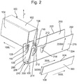
- Fig. 2 illustrates schematically an end of a carrier 210 and Fig. 3 illustrates the profile of a panel 100 for use with the carrier 210 of Fig. 2 .
- the panel 100 has a length 100L with a longitudinal extent extending in a longitudinal direction (the length direction) and, together with the illustrated profile, forms a front wall 102 extending between two mutually opposite sidewalls 104.
- Each of the sidewalls includes a respective lip 106 which extends not only in the longitudinal direction of the length 100L of the panel 100, but also transversely from the respective sidewalls 104.
- the front wall 102 faces in a first relative direction F and the lips 106 have support surfaces 108 which similarly face in the first relative direction F, but are spaced apart from the front wall 102.
- the lips 106 extend generally along or parallel with the front wall 102 and thus substantially perpendicular to the respective side walls 104, but lips 106 may alternatively extend slightly towards or away from the front wall 102, in other words, such that they are at an angle with the respective side walls 104 that is smaller or greater than 90 degrees, respectively. In the illustrated arrangement, the lips 106 extend slightly towards the front wall 102, in other words inwardly of the channel section formed by the front wall 102 and the sidewalls 104.
- Carriers may be provided for panels having lips which extend inwardly towards each other and inwardly of the channel formed by the front wall and sidewall.
- carriers may be provided to support panels having lips which face outwardly away from each other.
- the following description relates, merely by way of example, to carriers for use with panels such as that illustrated in Figure 3 with lips 106 which extend inwardly towards each other.
- the carrier 210 may include two carrier parts 200.
- Fig. 2 illustrates only the features necessary for the carrier 210 to support one panel 100. As illustrated in other Figures and discussed below, these features may be repeated at intervals along the length 200L of each carrier part 200.
- Each carrier part 200 includes a first edge 202 and a second edge 204 at opposite sides of the width W of the carrier part 200.
- the pair of carrier parts 200 are joined at their respective second edges 204.
- the second edges 204 of the carrier parts 200 are joined to each other by a support section 206 so that the carrier 210 has a generally U-shaped cross-sectional profile.
- the U-shaped cross-sectional profile includes corners or bent portions where the second edges 204 meet the support section 206.
- the support section 206 curves continuously into the carriers 200 so as to form a curved and smooth U-shaped profile.
- Fig 2 illustrates a fixing hole 208 through the support section 206 allowing the carrier 210 to be mounted relative to an architectural structure or surface, for example by means of a fastener, such as a screw.
- Each carrier part 200 includes, for each respective panel 100 to be supported, a pair of engaging surfaces 212 which face inwardly of the carrier part 200 with respect to its width 200W.
- the engaging surfaces 212 are configured to engage with the support surfaces 108 of a corresponding respective panel 100 and, with the panel 100 mounted to the carrier part 200, will face in the direction opposite to the first relative direction F of the panel 100, thereby preventing the panel 100 from moving away from the carrier part 200 in that first relative direction F.
- each carrier part 200 defines a plurality of channels 214 extending to and from the first edge 202 of the carrier part 200.
- Each channel 214 is configured to receive a respective sidewall 104 of a panel 100 so that the respective lip 106 and its support surface 108 is positioned adjacent an engaging surface 212 within the width 200W of the carrier part 200. This is illustrated (and will be discussed in further detail below) in Figs 4(a) and (b) .
- Fig. 2 also illustrates schematically a locking strip 300 for use with one of the carrier parts 200 of the carrier 210.
- the locking strip has a length 300L and a width 300W and has a generally planar sheet or plate-like form.
- the locking strip 300 is illustrated in Fig. 2 separated from the carrier part 200. However, in use, a locking face 302 of the locking strip 300 extending in the length 300L and 300W directions of the locking strip 300 is positioned against a carrier face 216 of the carrier part 200 extending in the length 200L and width 200W directions of the carrier part 200.
- Fig. 2 does not illustrate features for mounting the locking strip 300 to the carrier part 200, but various alternatives for these features will be discussed below.
- the locking strip 300 has an elongate edge 304 which extends along the length 300L of the locking strip 300. As will be described below, this is used for engaging, for example pressing against, the panels 100.
- the locking strip 300 also includes an edge 306 opposite to the elongate edge 304 with respect to the width 300W of the locking strip 300.
- a plurality of panels 100 are mounted on or fitted to two carriers 210, each having a pair of carrier parts 200.
- the carriers 210 are mounted horizontally, and the panels 100 are mounted on or fitted to the carrier parts 200 in a vertical orientation.
- the opposite sidewalls 104 extend through the channels 214 in the carrier parts 200.
- Fig. 4(a) show a carrier part 200 in an unlocked state and is a view from above the arrangement illustrated in Fig. 1(a) .
- the panels 100 are relatively free to move in the direction of their length 100L and width with respect to the carrier part 200.
- the purpose of the carrier system described herein is to improve any such engagement.
- the locking strip 300 has been positioned with the elongate edge 304 pressing on to the panels 100.
- the sidewalls 104 extend from the front wall 102 to edges 110 from which the lips 106 extend.
- the edges 110 form the furthermost extent of the panels 100 (from the front walls 102) against which the elongate edge 304 of the locking strip 300 can engage and press.
- the elongate edge 304 of the locking strip 300 engages with and/or presses against the panels 100 (as illustrated by means of the edges 110) and, thereby, engages with and/or presses the support surfaces 108 of the lips 106 against the engaging surfaces 212 of the carrier part 200.
- the locking strip 300 by means of mounting the locking strip 300 to the carrier part 200 in the locked position, it is possible to provide a more secure mounting of the panels 100 to the carrier part 200, in particular to enable mounting of the panels 100 with a slanted/angled or even vertical orientation as illustrated in Fig. 1(b) .
- the mounting arrangement may be particularly effective where the panels 100 themselves are at least partly elastically or plastically deformable so that the elongate edge 304 of the locking strip 300 may press into the surface of the panels 100 (along their edges 110) and the engaging surfaces 212 may press into the support surfaces 108 of the lips 106 of the panels 100.
- a coating on the elongate edge 304 and/or the engaging surfaces 212, for instance a rubber material, so as to improve engagement.
- a coating could be provided on appropriate surfaces of the panels 100.
- the locking strip 300 may have a planar form extending between the elongate edge 304 and the opposite elongate 306.
- the locking strip need not be planar and can have a curved form, for example bent, at one or more of its edges.
- Fig. 5 illustrates schematically the cross-section of an alternative locking strip 300'. This similarly has a locking face 302' and an elongate edge 304' which extends along the length of the locking strip 300' and is used for engaging, for example pressing against, the panels 100.
- the locking strip 300' includes an edge 306' opposite to the elongate edge 304' with respect to the width of the locking strip'.
- the locking strip curves away from, for example is bent, the locking face 302'.
- Any appropriate curved/bent structure may be used, but, in the illustrated arrangement, at a position proximate to the elongate edge 304', the portion of the locking strip 300' adjacent the elongate edge 304' is curved, for example bent, away from the rest (the planar extent) of the locking strip 300'.
- the portion adjacent the elongate edge 304' extends at an angle to the remainder of the locking strip 300' at an angle between 100° and 120°, preferably in the region of, substantially, 110°.
- the edge portion of the locking strip 300' By curving/bending the edge portion of the locking strip 300', stiffness is added to the locking strip 300'. Also, the elongate edge 304' contacts panels at an acute angle. As a result, the panels may be held in place more securely. Also, an improved distribution of force may be achieved so that all of the panels are held equally and the edge of the locking strip does not cut into the panels 100.
- Figs. 6(a) and (b) illustrate schematically use of the locking strip 300' in a locked and an unlocked position.
- Mounting of the locking strip 300 to the carrier part 200 in the locked position may be achieved in a number of different ways.
- a locking hole 220 may be provided in the support surface 216 through the thickness of the carrier 200 and a corresponding locking hole 320 may be provided in the locking face 302 of the locking strip 300 through the thickness of the locking strip 300.
- the two locking holes 220 and 320 are positioned such that, when they are aligned, the locking strip 300 is in the locked position for locking the mounting of the panels 100.
- a fastener of any appropriate type may be inserted through the two aligned locking holes 220 and 320 so as to secure the locking strip 300 in the locked position.
- one of the tow locking holes may be a blind hole and the fastener extends into that blind hole.
- the fastener may be preassembled in a state extending through one of the two locking holes 220 and 320.
- the fastener may replace one of the locking holes 220 and 320 so as to extend in the form of a pin or protrusion to be inserted through the remaining other of the locking holes 220 and 320.
- any of these locking arrangements can be provided repeatedly at intervals along the length of the carrier part 200 and locking strip 300 so as to provide additional support and strength to the mounting between the carrier part 200 and locking strip 300.
- the locking strip 300 is provided with a through hole 322 in the locking face extending through the thickness of the locking strip 300 and having an elongated extent having a path extending along the length 300L of the locking strip 300 and across the width 300W of the locking strip 300.
- the carrier part 200 includes a corresponding pin 222 which extends away from the carrier face through the elongate extent of the through hole 322. In this way, when the locking strip 300 is moved longitudinally in the direction of the length 200L of the carrier part 200 and the pin 222 traverses along the path of the elongate extent of the through hole 322, the locking strip 300 is moved widthwise in the direction of the width 300W of the carrier 200.
- a plurality of such through holes 322 and pins 222 may be provided at intervals along the length of the locking strip 300 and carrier 200 so as to provide additional support between the locking strips 300 and carrier 200.
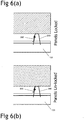
- Fig. 8(a) and (b) show cross-sectional views of the arrangement of Figs. 1(a) and (b) along the length of the two carriers 210, in particular with a cross-section through one of the panels 100 and the two carriers 210.
- Fig. 8(a) corresponds to the state of Fig. 4(a) with the locking strip 300 in the unlocked position spaced away from the edge 110 of the panel 100.
- Fig. 8(b) corresponds to Fig. 4(b) and illustrates the locking strip 300 in the locked position with the elongate edge 304 engaged with or pressed against the edge 110 of the panel 100.
- Figs. 9(a) and (b) show enlarged sections of Fig. 8(a) and (b) , in particular with respect to the lower of the two carriers 210.
- Fig. 9(b) illustrates that the elongate edge 304 of the locking strip 300 may press into the edge 110 of the panel 100 when the material of the panel 100 is in some way deformable.
- the pin 222 may be an integral part of the carrier part 200 extending out of the carrier face 216. However, the pin 222 may also be formed, as illustrated, as a separate part mounted in a through hole in the carrier part 200. For example, as illustrated in Figs 9(a) and (b) , the pin 222 may take the form a fitting to be pressed through the through hole 322 and through an aperture in the carrier part 200, with resilient features securing it to the other side of the carrier part 200 (opposite the carrier face 216). As illustrated, the pin 222 may also be provided with a flange 224 extending over the surface of the locking strip 300 (opposite to the locking face 302). This flange 224 acts to hold the locking strip 300 against the carrier part 200 with the locking face 302 against the carrier face 216.
- the carrier part 200 may be formed with a plurality of through holes in an array along the length of the carrier part 200 in the carrier face 216. Such holes may be used for the arrangement as described by attaching/mounting pins at predetermined intervals using those holes and providing a locking strip 300 with the elongate through hole 322 at appropriate intervals for use with the pins. In this way, it may be possible to make use of a carrier previously used only for suspending panels from a ceiling and modify that carrier to include the pins for mounting the locking strip 300.
- the locking strip discussed above is illustrated with ends (not discussed) that are substantially perpendicular to the longitudinal extent of the elongate edges. In other words, the ends extend substantially in the direction of the width 300W. This is not essential.
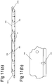
- the respective ends may take the form of side edges 350A and 350B that are slanted with respect to the elongate edges 304 and 306.
- This allows two locking strips 300 to be mounted adjacent to one another end-to-end.
- the path of the elongate through hole is angled/slanted relative to the elongate edges 304, 306, it becomes possible for an individual respective locking strip to be moved between its locked and unlocked positions whilst not interfering with the adjacent locking strip.
- the slanted angle of the side edges 350A, 350B corresponds to or is the same as the angle of the path of the elongate through holes 322.
- angles of the slants of the side edges 350A, 350B are similar to the angle of the path of the elongate through holes 322 and a corresponding gap is provided between the adjacent ends of respective locking strips to take account of any differences in the angles.
- the angle is between 18 and 28°, more preferably 21 to 24° and, in one particular example, approximately 23°, for example 23.3°.
- the locking strip illustrated in Figs. 10(a), 10(b) and 11(a) also includes a feature of providing an array of spaced slots along the elongate extent of the locking strip 300.
- the enlarged portion of "B" of Fig. 11(a) is illustrated in Fig. 11(b) to illustrate more clearly one of the slots 360.
- the slots 360 are configured to receive a tool, such as a conventional screwdriver. They are provided so as to allow this tool, such as the screwdriver, to engage in one of the slots 360 and allow a user to conveniently move and adjust the position of the locking strip 300. It will be appreciated that such an array of slots 360 can be provided, as appropriate, with any of the features of an array of locking strips as discussed.
- Fig. 12 illustrates an enlarged view of the through-hole 322.
- the path of the through hole 322 has a first end portion 324 which extends parallel with the length 300L of the locking strip 300.
- This first end portion 324 receives pin 222 when the locking strip 300 is in the locked position.
- an internal wall of the first end portion 324 presses on the pin 222 only in the direction of the width 300W of the locking strip 300.
- the locking strip 300 remains in the locking position and there is no tendency for the pin 222 to travel along the path allowing the locking strip 300 to return to the unlocked position.
- a second end portion 326 opposite first end portion 324 of the path of the through hole 322 also extends parallel with the length 300L of the locking strip 300. In the illustrated arrangement, this length is merely sufficient to receive the full extent of the pin 222, because, in the unlocked position in which the pin 222 is in the opposite second end portion 326, there is no particular force acting on the locking strip 300.
- the path of the through hole 322 extends diagonally across the width 300W of the locking strip 300 between the first end portion 324 and the opposite second end portion 326.
- Fig. 13 illustrates a variation to the path of Fig. 12 in which the first end portion 324 includes a small recess extending towards the opposite edge 306 of the locking strip 300.
- This slight recess 328 will, of course, allow the locking strip 300 to move slightly back towards the unlocked position, lessening the pressure exerted by the elongate edge 304 on the panels 100.
- the pin 222 will be retained more securely in this recess 328 so as to prevent the locking strip 300 moving in the direction of the length 200L of the carrier part 200. In other words, the locking strip 300 is more securely held from slipping from the locked position to the unlocked position.
- Fig. 14 illustrates another variation to the path of Fig. 12 in which the through hole 322 extends first diagonally across the width 300W of the locking strip 300 in the manner described above, but, then, along a section 322A towards/proximate the first end portion 324 extends diagonally in the opposite direction partially across the width 300W of the locking strip.
- the through hole 322 has a path which changes direction and extends at a slight angle towards the elongate edge 304 that is for contacting a panel 100.
- the elongate edge 304 of the locking strip 300 presses into the edge of the panel 100, temporarily deforming it before the locking strip 300 moves past the end formed by the angled shape of the path of the through hole 322. It is then locked into the seat formed by the first end portion 324.
- This arrangement may find particular advantageous application when used with more flexible panels, such a flexible felt panels.
- the elongate edge 304 of the locking strip may press into the resilient edge of the panel, temporarily deforming it. The geometry may ensure that the locking strip 300 stays in its locked position.
- Fig. 15 illustrates an alternative path for the elongate extent of the through hole 322.
- the path includes a section 330 which extends only in the direction of the width 300W of the locking strip 300.
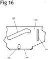
- Fig. 16 illustrates one end of a locking strip 300 which is provided with a slot 370 extending through the thickness of the locking strip 300 and across the width 300W of the locking strip 300.
- the slot 370 weakens the locking strip 300 with respect to its width and allows a user easily to bend the locking strip 300 about an axis extending with the elongate extent of the slot 370.
- the user may thus bend an end portion of the locking strip 300 with respect to its length so as to form a flange at that end of the locking strip 300.
- the flange provides a convenient part for a user to grip the locking strip 300 to move it between locked and unlocked positions. In use, a user will typically bend the end section by approximately 90°.
- a bending feature could be, instead of the slot 370 as illustrated, an array of individual holes or a reduction in the thickness of the locking strip 300 along a particular line.
- the bending feature preferably extends across the width 300W of the locking strip 300 substantially perpendicular to the edges 304, 306.
- a bending feature which extends across the width 300W at a different angle can still be used by the user to form an appropriate flange. Angles between 45 and 135° may be used and more preferably between 75 and 105°.
- Fig. 17(a) illustrates an alternative arrangement for the locking strip 300 where the through hole 322 does not include the first end portion 324 for securing the locking strip 300 in the locked position.
- One of the through holes 322 is illustrated in an enlarged view in Fig. 17(b) , together with an associated fixing hole 332 for receiving a fastener to secure the locking strip 300 in the locked position.
- the through hole 322 could be elongated in a path extending diagonally across the width of the locking strip 300, in the illustrated arrangement, the through hole 322 extends only in the direction of the width 300W of the locking strip 300.
- the fixing hole 322 is aligned with a through hole in the carrier part 200 and may be fixed from further movement by inserting a fastener in a similar manner to that described above with reference to Fig. 7 .
- the locking strip 300 may be provided with a protrusion 334 on the locking face 302 of the locking strip 300.
- This protrusion 334 is configured to align with a corresponding recess or aperture in the carrier face 216 of the carrier part 200 when the locking strip 300 is in the locked position. In this way, the locking strip 300 may be held relative to the carrier part 200 in the locked position.
- Such a protrusion 334 may similarly be used on the locking strip 300 having through holes 322 which extend diagonally across the width of the locking strip 300.
- the features described as part of the locking strip 300 and the features described as being part of the carrier part 200 may be replaced with each other, ie interchanged, for example with the through hole being provided in the carrier part 200 for guiding a pin on the locking strip 300 and the protrusion being provided on the carrier face for engaging in a recess or aperture in the locking strip 300 and for securing the locking strip in the locked position.
- mounting arrangements described above are configured to provide relative linear motion between the locking strip 300 and the carrier part 200 when moving between unlocked and locked positions.
- mounting arrangements may provide for relative rotational movement.
- the locking strip 300 may pivot relative to the carrier part 200 about a longitudinal axis, for example extending parallel with the length 300L of the locking strip 300, the length 200L of the locking part 200 and the elongate edge 304.
- the locking strip 300 may be rotated about the pivot from an unlocked position as illustrated in Fig. 19(a) to a locked position as illustrated in Fig. 13(b) .
- an extension or flange may be provided along the elongate edge 304.
- the opposite edge 306 of the locking strip 300 may engage with a portion of the carrier part 200 so as to allow relative rotation whilst being secured in the locked position.
- the locking strip 300 and carrier part 200 may include bent portions and recesses which fit into one another allowing the locking strip 300 to rotate to the locked position and then be secured in the locked position.
- extensions from the opposite edge 306 of the locking strip 300 may be configured to extend through apertures in the carrier part 200.
- Spring clips may be provided for fastening the elongate edge 304 (or an extension thereof) to the carrier part 200 with the locking face 302 against the carrier face 216 in the locked position.
- such spring clips may be provided at portions between adjacent panels.
Landscapes
- Engineering & Computer Science (AREA)
- Architecture (AREA)
- Civil Engineering (AREA)
- Structural Engineering (AREA)
- Physics & Mathematics (AREA)
- Electromagnetism (AREA)
- General Engineering & Computer Science (AREA)
- Mechanical Engineering (AREA)
- Finishing Walls (AREA)
- Clamps And Clips (AREA)
Priority Applications (1)
| Application Number | Priority Date | Filing Date | Title |
|---|---|---|---|
| PL18211383T PL3498933T3 (pl) | 2017-12-14 | 2018-12-10 | System do montażu wielu paneli |
Applications Claiming Priority (1)
| Application Number | Priority Date | Filing Date | Title |
|---|---|---|---|
| GB1720875.2A GB2569346B (en) | 2017-12-14 | 2017-12-14 | System for mounting a plurality of panels |
Publications (2)
| Publication Number | Publication Date |
|---|---|
| EP3498933A1 EP3498933A1 (en) | 2019-06-19 |
| EP3498933B1 true EP3498933B1 (en) | 2020-10-28 |
Family
ID=61009062
Family Applications (1)
| Application Number | Title | Priority Date | Filing Date |
|---|---|---|---|
| EP18211383.7A Active EP3498933B1 (en) | 2017-12-14 | 2018-12-10 | System for mounting a plurality of panels |
Country Status (6)
| Country | Link |
|---|---|
| US (1) | US10689850B2 (pl) |
| EP (1) | EP3498933B1 (pl) |
| CA (1) | CA3027608A1 (pl) |
| DK (1) | DK3498933T3 (pl) |
| GB (1) | GB2569346B (pl) |
| PL (1) | PL3498933T3 (pl) |
Families Citing this family (13)
| Publication number | Priority date | Publication date | Assignee | Title |
|---|---|---|---|---|
| WO2020061034A1 (en) * | 2018-09-19 | 2020-03-26 | Fiber Composites, LLC (dba Fiberon) | Siding clip |
| US11459770B1 (en) * | 2019-04-16 | 2022-10-04 | Gary E. Gotfredson | Metal wall panel system |
| USD956268S1 (en) | 2019-08-01 | 2022-06-28 | Hunter Douglas Industries B.V. | Ceiling panel |
| GB201915927D0 (en) * | 2019-11-01 | 2019-12-18 | Hunter Douglas Ind Bv | Ceiling panel support system |
| DK180642B1 (en) * | 2020-01-30 | 2021-11-10 | Troldtekt As | Wall or ceiling covering system |
| CA3171601A1 (en) | 2020-03-25 | 2021-09-30 | Nathan J. Baxter | Ceiling system and carrier component thereof |
| WO2022016079A1 (en) | 2020-07-17 | 2022-01-20 | Certainteed Ceilings Corporation | Multi-level carrier for ceiling panels and ceiling panel system |
| CA3186046A1 (en) * | 2020-08-28 | 2022-03-03 | Jesper Wolff | Lamella wall system |
| US12209407B1 (en) * | 2021-01-20 | 2025-01-28 | Gordon Sales, Inc. | Narrow gap filling structure |
| US12024881B1 (en) | 2021-01-20 | 2024-07-02 | Gordon Sales, Inc. | Telescoping wall gap filler assembly |
| US11767675B1 (en) * | 2022-06-17 | 2023-09-26 | David ATIAS | Customizable cladding system and method |
| USD1070124S1 (en) * | 2023-02-18 | 2025-04-08 | Pravin Nanayakkara | Anchor joist for architectural structures |
| KR102699898B1 (ko) * | 2023-11-28 | 2024-08-29 | 주식회사 주신기업 | 스냅 캐리어를 이용한 건축물 루버 구조체 |
Family Cites Families (16)
| Publication number | Priority date | Publication date | Assignee | Title |
|---|---|---|---|---|
| DE1509485A1 (de) * | 1965-07-16 | 1969-05-08 | Hunter Douglas | Wand- oder Deckenbekleidung mit laenglichen Lamellenkoerpern |
| CA1096578A (en) * | 1978-10-31 | 1981-03-03 | Paul Van Leeuwen | Panel carrier and panel construction incorporating such carrier |
| DE2927969A1 (de) * | 1979-07-11 | 1981-02-05 | Dornier Gmbh | Bauelementensatz zur verkleidung von decken, waenden o.dgl. |
| US4309858A (en) * | 1979-12-07 | 1982-01-12 | Levolor Lorentzen, Inc. | Support for ceiling panels |
| US4328653A (en) * | 1980-01-23 | 1982-05-11 | Levolor Lorentzen, Inc. | Ceiling panel clip |
| GB2080356B (en) * | 1980-06-17 | 1984-02-01 | Hunter Douglas Ind Bv | Panelling and carriers therefor |
| AT382917B (de) * | 1982-07-14 | 1987-04-27 | Hunter Douglas Ind Bv | Wand- oder deckenverkleidung, bestehend aus paneelen |
| GB2145130B (en) * | 1983-08-16 | 1986-08-13 | Hunter Douglas Ind Bv | Panelling system and carrier therefor |
| CA1243181A (en) * | 1985-01-08 | 1988-10-18 | Michael Slapsys | Linear panel ceilings and the like |
| US4987715A (en) * | 1986-03-31 | 1991-01-29 | Chicago Metallic Corporation | Parallel beam system |
| DE9310064U1 (de) * | 1993-07-02 | 1993-09-02 | Genschorek, Gido, 15827 Dahlewitz | Vorrichtung zur Befestigung von plattenförmigen Bauteilen an Bauwerken |
| US5590503A (en) * | 1993-10-26 | 1997-01-07 | Semper Sealing Systems Inc. | Non-composite panel |
| DK1522646T3 (da) * | 1998-09-15 | 2007-03-19 | Hunter Douglas Ind Bv | Låseclips |
| US6629391B1 (en) * | 2000-07-06 | 2003-10-07 | Vkr Holding A/S | Window for installation in a roof and a mounting bracket for use in the installation of roof penetrating structures |
| US7293393B2 (en) * | 2004-01-27 | 2007-11-13 | Worthington Armstrong Venture | Perimeter clip for seismic ceilings |
| KR101497877B1 (ko) * | 2014-08-29 | 2015-03-04 | 이화중 | 마감재 지지 바아가 직접 결합되는 방식의 캐리어 |
-
2017
- 2017-12-14 GB GB1720875.2A patent/GB2569346B/en active Active
-
2018
- 2018-12-10 PL PL18211383T patent/PL3498933T3/pl unknown
- 2018-12-10 DK DK18211383.7T patent/DK3498933T3/da active
- 2018-12-10 EP EP18211383.7A patent/EP3498933B1/en active Active
- 2018-12-13 US US16/219,037 patent/US10689850B2/en active Active
- 2018-12-14 CA CA3027608A patent/CA3027608A1/en active Pending
Non-Patent Citations (1)
| Title |
|---|
| None * |
Also Published As
| Publication number | Publication date |
|---|---|
| GB2569346A (en) | 2019-06-19 |
| GB201720875D0 (en) | 2018-01-31 |
| GB2569346B (en) | 2020-09-09 |
| DK3498933T3 (da) | 2020-12-07 |
| US10689850B2 (en) | 2020-06-23 |
| US20190186134A1 (en) | 2019-06-20 |
| EP3498933A1 (en) | 2019-06-19 |
| PL3498933T3 (pl) | 2021-09-20 |
| CA3027608A1 (en) | 2019-06-14 |
Similar Documents
| Publication | Publication Date | Title |
|---|---|---|
| US10689850B2 (en) | System for mounting a plurality of panels | |
| US12428840B2 (en) | Ceiling system | |
| US12049759B2 (en) | Linear surface covering system | |
| US10174501B1 (en) | Metal baffles | |
| US2712917A (en) | Cable clip or the like | |
| US4041668A (en) | Clip structure for a concealed grid structure of a suspended ceiling | |
| US4272937A (en) | Panel construction | |
| US12006684B2 (en) | Ceiling grid hanger assembly with indexing tabs | |
| WO1997025507B1 (en) | Sliding door corner connector | |
| EP0871814A4 (en) | CORNER CONNECTOR FOR SLIDING DOORS | |
| KR102341552B1 (ko) | 바닥 부재의 고정 구조 | |
| EP4051844A1 (en) | Ceiling panel support system | |
| US4157000A (en) | Mounting device for ceiling members | |
| US3278980A (en) | Folding door mounting assembly and bracket therefor | |
| US20250092676A1 (en) | Linear metal ceilings | |
| US4987715A (en) | Parallel beam system | |
| CN118793680A (zh) | 紧固件 | |
| JP2002146965A (ja) | 天井パネル |
Legal Events
| Date | Code | Title | Description |
|---|---|---|---|
| PUAI | Public reference made under article 153(3) epc to a published international application that has entered the european phase |
Free format text: ORIGINAL CODE: 0009012 |
|
| STAA | Information on the status of an ep patent application or granted ep patent |
Free format text: STATUS: THE APPLICATION HAS BEEN PUBLISHED |
|
| AK | Designated contracting states |
Kind code of ref document: A1 Designated state(s): AL AT BE BG CH CY CZ DE DK EE ES FI FR GB GR HR HU IE IS IT LI LT LU LV MC MK MT NL NO PL PT RO RS SE SI SK SM TR |
|
| AX | Request for extension of the european patent |
Extension state: BA ME |
|
| STAA | Information on the status of an ep patent application or granted ep patent |
Free format text: STATUS: REQUEST FOR EXAMINATION WAS MADE |
|
| 17P | Request for examination filed |
Effective date: 20191204 |
|
| RBV | Designated contracting states (corrected) |
Designated state(s): AL AT BE BG CH CY CZ DE DK EE ES FI FR GB GR HR HU IE IS IT LI LT LU LV MC MK MT NL NO PL PT RO RS SE SI SK SM TR |
|
| GRAP | Despatch of communication of intention to grant a patent |
Free format text: ORIGINAL CODE: EPIDOSNIGR1 |
|
| RIC1 | Information provided on ipc code assigned before grant |
Ipc: E04B 9/24 20060101ALI20200409BHEP Ipc: E04F 13/08 20060101AFI20200409BHEP Ipc: E04F 13/12 20060101ALI20200409BHEP Ipc: E04B 9/36 20060101ALI20200409BHEP |
|
| STAA | Information on the status of an ep patent application or granted ep patent |
Free format text: STATUS: GRANT OF PATENT IS INTENDED |
|
| INTG | Intention to grant announced |
Effective date: 20200514 |
|
| GRAS | Grant fee paid |
Free format text: ORIGINAL CODE: EPIDOSNIGR3 |
|
| GRAA | (expected) grant |
Free format text: ORIGINAL CODE: 0009210 |
|
| STAA | Information on the status of an ep patent application or granted ep patent |
Free format text: STATUS: THE PATENT HAS BEEN GRANTED |
|
| RBV | Designated contracting states (corrected) |
Designated state(s): AL AT BE BG CH CY CZ DE DK EE ES FI FR GR HR HU IE IS IT LI LT LU LV MC MK MT NL NO PL PT RO RS SE SI SK SM TR |
|
| AK | Designated contracting states |
Kind code of ref document: B1 Designated state(s): AL AT BE BG CH CY CZ DE DK EE ES FI FR GR HR HU IE IS IT LI LT LU LV MC MK MT NL NO PL PT RO RS SE SI SK SM TR |
|
| REG | Reference to a national code |
Ref country code: CH Ref legal event code: EP |
|
| REG | Reference to a national code |
Ref country code: AT Ref legal event code: REF Ref document number: 1328384 Country of ref document: AT Kind code of ref document: T Effective date: 20201115 |
|
| REG | Reference to a national code |
Ref country code: DE Ref legal event code: R096 Ref document number: 602018009127 Country of ref document: DE |
|
| REG | Reference to a national code |
Ref country code: IE Ref legal event code: FG4D |
|
| REG | Reference to a national code |
Ref country code: DK Ref legal event code: T3 Effective date: 20201202 |
|
| REG | Reference to a national code |
Ref country code: NL Ref legal event code: FP |
|
| REG | Reference to a national code |
Ref country code: CH Ref legal event code: NV Representative=s name: VENI GMBH, CH |
|
| REG | Reference to a national code |
Ref country code: AT Ref legal event code: MK05 Ref document number: 1328384 Country of ref document: AT Kind code of ref document: T Effective date: 20201028 |
|
| PG25 | Lapsed in a contracting state [announced via postgrant information from national office to epo] |
Ref country code: PT Free format text: LAPSE BECAUSE OF FAILURE TO SUBMIT A TRANSLATION OF THE DESCRIPTION OR TO PAY THE FEE WITHIN THE PRESCRIBED TIME-LIMIT Effective date: 20210301 Ref country code: RS Free format text: LAPSE BECAUSE OF FAILURE TO SUBMIT A TRANSLATION OF THE DESCRIPTION OR TO PAY THE FEE WITHIN THE PRESCRIBED TIME-LIMIT Effective date: 20201028 Ref country code: FI Free format text: LAPSE BECAUSE OF FAILURE TO SUBMIT A TRANSLATION OF THE DESCRIPTION OR TO PAY THE FEE WITHIN THE PRESCRIBED TIME-LIMIT Effective date: 20201028 Ref country code: NO Free format text: LAPSE BECAUSE OF FAILURE TO SUBMIT A TRANSLATION OF THE DESCRIPTION OR TO PAY THE FEE WITHIN THE PRESCRIBED TIME-LIMIT Effective date: 20210128 Ref country code: GR Free format text: LAPSE BECAUSE OF FAILURE TO SUBMIT A TRANSLATION OF THE DESCRIPTION OR TO PAY THE FEE WITHIN THE PRESCRIBED TIME-LIMIT Effective date: 20210129 |
|
| REG | Reference to a national code |
Ref country code: LT Ref legal event code: MG4D |
|
| PG25 | Lapsed in a contracting state [announced via postgrant information from national office to epo] |
Ref country code: SE Free format text: LAPSE BECAUSE OF FAILURE TO SUBMIT A TRANSLATION OF THE DESCRIPTION OR TO PAY THE FEE WITHIN THE PRESCRIBED TIME-LIMIT Effective date: 20201028 Ref country code: IS Free format text: LAPSE BECAUSE OF FAILURE TO SUBMIT A TRANSLATION OF THE DESCRIPTION OR TO PAY THE FEE WITHIN THE PRESCRIBED TIME-LIMIT Effective date: 20210228 Ref country code: LV Free format text: LAPSE BECAUSE OF FAILURE TO SUBMIT A TRANSLATION OF THE DESCRIPTION OR TO PAY THE FEE WITHIN THE PRESCRIBED TIME-LIMIT Effective date: 20201028 Ref country code: BG Free format text: LAPSE BECAUSE OF FAILURE TO SUBMIT A TRANSLATION OF THE DESCRIPTION OR TO PAY THE FEE WITHIN THE PRESCRIBED TIME-LIMIT Effective date: 20210128 Ref country code: AT Free format text: LAPSE BECAUSE OF FAILURE TO SUBMIT A TRANSLATION OF THE DESCRIPTION OR TO PAY THE FEE WITHIN THE PRESCRIBED TIME-LIMIT Effective date: 20201028 Ref country code: ES Free format text: LAPSE BECAUSE OF FAILURE TO SUBMIT A TRANSLATION OF THE DESCRIPTION OR TO PAY THE FEE WITHIN THE PRESCRIBED TIME-LIMIT Effective date: 20201028 |
|
| PG25 | Lapsed in a contracting state [announced via postgrant information from national office to epo] |
Ref country code: HR Free format text: LAPSE BECAUSE OF FAILURE TO SUBMIT A TRANSLATION OF THE DESCRIPTION OR TO PAY THE FEE WITHIN THE PRESCRIBED TIME-LIMIT Effective date: 20201028 |
|
| REG | Reference to a national code |
Ref country code: DE Ref legal event code: R097 Ref document number: 602018009127 Country of ref document: DE |
|
| PG25 | Lapsed in a contracting state [announced via postgrant information from national office to epo] |
Ref country code: RO Free format text: LAPSE BECAUSE OF FAILURE TO SUBMIT A TRANSLATION OF THE DESCRIPTION OR TO PAY THE FEE WITHIN THE PRESCRIBED TIME-LIMIT Effective date: 20201028 Ref country code: LT Free format text: LAPSE BECAUSE OF FAILURE TO SUBMIT A TRANSLATION OF THE DESCRIPTION OR TO PAY THE FEE WITHIN THE PRESCRIBED TIME-LIMIT Effective date: 20201028 Ref country code: SM Free format text: LAPSE BECAUSE OF FAILURE TO SUBMIT A TRANSLATION OF THE DESCRIPTION OR TO PAY THE FEE WITHIN THE PRESCRIBED TIME-LIMIT Effective date: 20201028 Ref country code: SK Free format text: LAPSE BECAUSE OF FAILURE TO SUBMIT A TRANSLATION OF THE DESCRIPTION OR TO PAY THE FEE WITHIN THE PRESCRIBED TIME-LIMIT Effective date: 20201028 Ref country code: EE Free format text: LAPSE BECAUSE OF FAILURE TO SUBMIT A TRANSLATION OF THE DESCRIPTION OR TO PAY THE FEE WITHIN THE PRESCRIBED TIME-LIMIT Effective date: 20201028 Ref country code: CZ Free format text: LAPSE BECAUSE OF FAILURE TO SUBMIT A TRANSLATION OF THE DESCRIPTION OR TO PAY THE FEE WITHIN THE PRESCRIBED TIME-LIMIT Effective date: 20201028 |
|
| PG25 | Lapsed in a contracting state [announced via postgrant information from national office to epo] |
Ref country code: MC Free format text: LAPSE BECAUSE OF FAILURE TO SUBMIT A TRANSLATION OF THE DESCRIPTION OR TO PAY THE FEE WITHIN THE PRESCRIBED TIME-LIMIT Effective date: 20201028 |
|
| PLBE | No opposition filed within time limit |
Free format text: ORIGINAL CODE: 0009261 |
|
| STAA | Information on the status of an ep patent application or granted ep patent |
Free format text: STATUS: NO OPPOSITION FILED WITHIN TIME LIMIT |
|
| 26N | No opposition filed |
Effective date: 20210729 |
|
| PG25 | Lapsed in a contracting state [announced via postgrant information from national office to epo] |
Ref country code: AL Free format text: LAPSE BECAUSE OF FAILURE TO SUBMIT A TRANSLATION OF THE DESCRIPTION OR TO PAY THE FEE WITHIN THE PRESCRIBED TIME-LIMIT Effective date: 20201028 Ref country code: IE Free format text: LAPSE BECAUSE OF NON-PAYMENT OF DUE FEES Effective date: 20201210 Ref country code: LU Free format text: LAPSE BECAUSE OF NON-PAYMENT OF DUE FEES Effective date: 20201210 Ref country code: IT Free format text: LAPSE BECAUSE OF FAILURE TO SUBMIT A TRANSLATION OF THE DESCRIPTION OR TO PAY THE FEE WITHIN THE PRESCRIBED TIME-LIMIT Effective date: 20201028 |
|
| PG25 | Lapsed in a contracting state [announced via postgrant information from national office to epo] |
Ref country code: SI Free format text: LAPSE BECAUSE OF FAILURE TO SUBMIT A TRANSLATION OF THE DESCRIPTION OR TO PAY THE FEE WITHIN THE PRESCRIBED TIME-LIMIT Effective date: 20201028 |
|
| PG25 | Lapsed in a contracting state [announced via postgrant information from national office to epo] |
Ref country code: IS Free format text: LAPSE BECAUSE OF FAILURE TO SUBMIT A TRANSLATION OF THE DESCRIPTION OR TO PAY THE FEE WITHIN THE PRESCRIBED TIME-LIMIT Effective date: 20210228 Ref country code: TR Free format text: LAPSE BECAUSE OF FAILURE TO SUBMIT A TRANSLATION OF THE DESCRIPTION OR TO PAY THE FEE WITHIN THE PRESCRIBED TIME-LIMIT Effective date: 20201028 Ref country code: MT Free format text: LAPSE BECAUSE OF FAILURE TO SUBMIT A TRANSLATION OF THE DESCRIPTION OR TO PAY THE FEE WITHIN THE PRESCRIBED TIME-LIMIT Effective date: 20201028 Ref country code: CY Free format text: LAPSE BECAUSE OF FAILURE TO SUBMIT A TRANSLATION OF THE DESCRIPTION OR TO PAY THE FEE WITHIN THE PRESCRIBED TIME-LIMIT Effective date: 20201028 |
|
| PG25 | Lapsed in a contracting state [announced via postgrant information from national office to epo] |
Ref country code: MK Free format text: LAPSE BECAUSE OF FAILURE TO SUBMIT A TRANSLATION OF THE DESCRIPTION OR TO PAY THE FEE WITHIN THE PRESCRIBED TIME-LIMIT Effective date: 20201028 |
|
| P01 | Opt-out of the competence of the unified patent court (upc) registered |
Effective date: 20230331 |
|
| REG | Reference to a national code |
Ref country code: CH Ref legal event code: U11 Free format text: ST27 STATUS EVENT CODE: U-0-0-U10-U11 (AS PROVIDED BY THE NATIONAL OFFICE) Effective date: 20260101 |
|
| PGFP | Annual fee paid to national office [announced via postgrant information from national office to epo] |
Ref country code: DK Payment date: 20251222 Year of fee payment: 8 |
|
| PGFP | Annual fee paid to national office [announced via postgrant information from national office to epo] |
Ref country code: NL Payment date: 20251222 Year of fee payment: 8 Ref country code: FR Payment date: 20251230 Year of fee payment: 8 |
|
| PGFP | Annual fee paid to national office [announced via postgrant information from national office to epo] |
Ref country code: PL Payment date: 20251114 Year of fee payment: 8 |
|
| PGFP | Annual fee paid to national office [announced via postgrant information from national office to epo] |
Ref country code: DE Payment date: 20251229 Year of fee payment: 8 |
|
| PGFP | Annual fee paid to national office [announced via postgrant information from national office to epo] |
Ref country code: BE Payment date: 20260109 Year of fee payment: 8 |
|
| PGFP | Annual fee paid to national office [announced via postgrant information from national office to epo] |
Ref country code: CH Payment date: 20260101 Year of fee payment: 8 |