EP3498903A1 - Compound needle - Google Patents
Compound needle Download PDFInfo
- Publication number
- EP3498903A1 EP3498903A1 EP18212359.6A EP18212359A EP3498903A1 EP 3498903 A1 EP3498903 A1 EP 3498903A1 EP 18212359 A EP18212359 A EP 18212359A EP 3498903 A1 EP3498903 A1 EP 3498903A1
- Authority
- EP
- European Patent Office
- Prior art keywords
- blade
- slider
- region
- fitting
- exposed
- Prior art date
- Legal status (The legal status is an assumption and is not a legal conclusion. Google has not performed a legal analysis and makes no representation as to the accuracy of the status listed.)
- Granted
Links
Images



Classifications
-
- D—TEXTILES; PAPER
- D04—BRAIDING; LACE-MAKING; KNITTING; TRIMMINGS; NON-WOVEN FABRICS
- D04B—KNITTING
- D04B15/00—Details of, or auxiliary devices incorporated in, weft knitting machines, restricted to machines of this kind
- D04B15/20—Needle bars
-
- D—TEXTILES; PAPER
- D04—BRAIDING; LACE-MAKING; KNITTING; TRIMMINGS; NON-WOVEN FABRICS
- D04B—KNITTING
- D04B35/00—Details of, or auxiliary devices incorporated in, knitting machines, not otherwise provided for
- D04B35/02—Knitting tools or instruments not provided for in group D04B15/00 or D04B27/00
- D04B35/06—Sliding-tongue needles
-
- D—TEXTILES; PAPER
- D04—BRAIDING; LACE-MAKING; KNITTING; TRIMMINGS; NON-WOVEN FABRICS
- D04B—KNITTING
- D04B35/00—Details of, or auxiliary devices incorporated in, knitting machines, not otherwise provided for
- D04B35/02—Knitting tools or instruments not provided for in group D04B15/00 or D04B27/00
-
- D—TEXTILES; PAPER
- D04—BRAIDING; LACE-MAKING; KNITTING; TRIMMINGS; NON-WOVEN FABRICS
- D04B—KNITTING
- D04B35/00—Details of, or auxiliary devices incorporated in, knitting machines, not otherwise provided for
- D04B35/02—Knitting tools or instruments not provided for in group D04B15/00 or D04B27/00
- D04B35/04—Latch needles
-
- D—TEXTILES; PAPER
- D04—BRAIDING; LACE-MAKING; KNITTING; TRIMMINGS; NON-WOVEN FABRICS
- D04B—KNITTING
- D04B35/00—Details of, or auxiliary devices incorporated in, knitting machines, not otherwise provided for
- D04B35/02—Knitting tools or instruments not provided for in group D04B15/00 or D04B27/00
- D04B35/08—Spring or bearded needles
Definitions
- the present invention relates to a compound needle that includes a needle body and a slider.
- a needle used in a flat knitting machine is a compound needle that includes a needle body with a hook, and a slider that moves relative to the needle body (e.g., see Patent Document 1) .
- the slider is slidably fitted into a slider groove that is formed in the needle body, and slides with respect to the needle body to open and close the hook.
- the slider includes a first slider (blade) that has, at a leading end, a tongue, which serves as a portion for opening and closing the hook, and a second slider (slider body) that is mounted at a rear end of the first slider.
- the first slider is made of two laminar members that have substantially the same shape and are laid overlapping each other, and the first slider is accommodated in the slider groove formed in the needle body.
- the second slider has, on one side thereof, a longitudinal groove (fitting groove) into which the rear end of the first slider is fitted.
- the first slider and the second slider are integrated through crimping, for example, the side walls of the longitudinal groove in the second slider in a state in which the rear end of the first slider is fitted into the longitudinal groove in the second slider.
- Patent Document 1 JP 2946323B
- the fixation of the first slider and the second slider using crimping is realized by plastically deforming the constituent material of the second slider at a boundary portion, on the surface side, between the first slider and the second slider, so that the constituent material of the second slider partially covers the surface of the laminar member of the first slider that is located on the opening side of the longitudinal groove.
- Patent Document 1 the two laminar members having substantially the same shape are laid overlapping each other in the longitudinal groove in the second slider, and thus there is the risk that the fixed portion between the first slider (two laminar members) and the second slider that was made through the crimping may become loose with time.
- the constituent material of the second slider that was plastically deformed through the crimping directly acts on one of the two laminar members that is located on the opening side of the longitudinal groove, but does not actually act on the other one that is located on the bottom side of the longitudinal groove.
- the reason is that the one of the two laminar members that is located on the bottom side of the longitudinal groove is not directly fixed to the second slider. If the laminar member located on the bottom side of the longitudinal groove is not directly fixed to the second slider, the first slider and the second slider will be likely to become loose with time under application of a moment to the boundary portion between the first slider and the second slider.
- the present invention was made in view of the above-described circumstances, and it is an object thereof to provide a compound needle in which a connected portion of a slider having two blades laid overlapping each other is rigidly fixed.
- a compound needle includes a needle body that has a hook, and a slider configured to move relative to the needle body to open and close the hook, wherein the slider includes:
- the inner blade is longer in a longitudinal direction than the outer blade, and includes an exposed region that is formed by the part of the surface of the inner fitting region that is exposed to the outside.
- the inner blade includes, in the exposed region, a rear cutout portion from which part of the bottom of the fitting groove is exposed.
- the outer blade includes, in the outer fitting region, an outer cutout portion from which part of the surface of the inner fitting region is exposed to the outside.
- the inner blade includes, at a position in the inner fitting region that corresponds to the outer cutout portion, an inner cutout portion from which part of the bottom of the fitting groove is exposed to the outside.
- the constituent material of the slider body that was plastically deformed through the crimping can directly act on both the inner blade and the outer blade. Specifically, by crimping an opening edge of the fitting groove of the slider body in the vicinity of the exposed part of the inner fitting region, the plastically deformed constituent material of the slider body can cover the exposed part of the inner fitting region.
- the inner blade can be directly fixed to the slider body.
- the outer blade can be directly fixed to the slider body, by crimping an opening edge of the fitting groove of the slider body. This is because the substantially entire surface of the outer blade is exposed to the outside, and thus the plastically deformed constituent material of the slider body can cover the surface of the region (outer fitting region) of the outer blade that is fitted into the fitting groove.
- the slider body and the two blades are rigidly fixed to each other. Accordingly, even if a moment is continuously applied to a boundary portion between the slider body and the two blades, it is possible to prevent the slider body and the two blades from becoming loose with time.
- the inner blade includes the exposed region that is formed by the inner blade being longer than the outer blade, part of the surface of the inner fitting region can be easily exposed. As a result of the inner blade including the exposed region, it is possible to enhance the degree of freedom of the positions and the number of the crimped portions, depending on the difference in length between the inner blade and the outer blade.
- the exposed region including the rear cutout portion part of the bottom of the fitting groove is exposed to the outside. Accordingly, by crimping an opening edge of the fitting groove of the slider body in the vicinity of the exposed region, the constituent material of the slider body that is subject to plastic deformation enters the rear cutout portion, and is provided in a space formed by the bottom and the wall side of the fitting groove, and the side face (face along the thickness direction of the inner blade) of the inner fitting region. Accordingly, the plastically deformed constituent material of the slider body not only covers the exposed region of the inner fitting region but also supports the side face of the inner fitting region, thus making it possible to fix the inner blade to the slider body more rigidly.
- outer fitting region including the outer cutout portion part of the surface of the inner fitting region can be easily exposed. Furthermore, as a result of the outer fitting region including the outer cutout portion, blades having substantially the same outer shape and length can be used, and the inner blade and the outer blade can be easily laid on the slider body.
- the constituent material of the slider body that is subject to plastic deformation enters the inner cutout portion via the outer cutout portion, and is provided in a space formed by the bottom and the wall side of the fitting groove, and the side face (face along the thickness direction of the inner blade) of the inner fitting region. Accordingly, the plastically deformed constituent material of the slider body not only covers the exposed part of the inner fitting region but also supports the side face of the inner fitting region, thus making it possible to rigidly fix the inner blade to the slider body.
- a compound needle 1 ⁇ according to a first embodiment will be described with reference to FIGS. 1A, 1B , 2 , 3A, and 3B .
- the upper and lower sides with respect to the paper plane in FIGS. 1A and 1B , FIG. 2 , and FIG. 3A are respectively the front and rear sides of the compound needle 1 ⁇
- the right and left sides with respect to the paper plane are respectively the lower and upper sides of the compound needle 1 ⁇
- the depth direction with respect to the paper plane is the thickness direction of the compound needle 1 ⁇ .
- the far and near sides with respect to the paper plane are respectively the front and rear sides of the compound needle 1 ⁇
- the right and left sides with respect to the paper plane are respectively the lower and upper sides of the compound needle 1 ⁇
- the vertical direction with respect to the paper plane is the thickness direction of the compound needle 1 ⁇ .
- the compound needle 1 ⁇ includes a needle body 2 that has a hook 20, and a slider 3 that moves relative to the needle body 2 to open and close the hook 20.
- the compound needle 1 ⁇ of the present embodiment can be used in a two-bed flat knitting machine or a four-bed flat knitting machine. The configurations of the compound needle 1 ⁇ of the first embodiment will be described in detail below.
- the needle body 2 includes the hook 20 provided at a leading end, and a slider groove 21 formed in an upper face on the leading end side.
- Blades an inner blade 5 and an outer blade 6) of the later-described slider 3 are slidably fitted into the slider groove 21 (see FIGS. 1A and 1B ).
- the slider 3 (the inner blade 5 and the outer blade 6) slides with respect to the needle body 2 to open and close the hook 20.
- the open/close operation of the hook 20 will be described in detail later when the inner blade 5 and the outer blade 6 are described.
- the needle body 2 has, on the upper face on the rear end side, an engaging portion 22 that protrudes upward so as to abut against the slider 3, and defines the retraction limit position when the slider 3 slides.
- the slider 3 includes a slider body 4, and the inner blade 5 and the outer blade 6 that are mounted on the slider body 4. As shown in FIGS. 3A and 3B , the inner blade 5 and the outer blade 6 are fixed to the slider body 4 with crimped portions 7, which are formed by crimping the surface of the slider body 4.
- regions in which the crimped portions 7 are provided are schematically shown by hatched rectangles.
- the slider body 4 includes a coupling portion 40 that protrudes downward from the lower face thereof.
- the coupling portion 40 has a certain length in a longitudinal direction of the slider body 4.
- the slider body 4 has a fitting groove 41 that is formed in a side surface (surface on the near side with respect to the paper plane of FIGS. 1A, 1B , and 2 ) of the coupling portion 40, the fitting groove 41 extending in the longitudinal direction of the coupling portion 40. By being fitted into the fitting groove 41, the later-described inner blade 5 and the outer blade 6 are coupled to the slider body 4. As shown in FIG.
- the fitting groove 41 includes a bottom 41b, and wall sides 41s, which extend in the longitudinal direction of the slider body 4 and are perpendicular to the bottom 41b, and the fitting groove 41 has an opening 41o on the side opposite to the bottom 41b.
- the slider body 4 includes a recess 410 that is recessed from the fitting groove 41 to the upper side of the slider body 4.
- the recess 410 is a through hole that penetrates the slider body 4 in the thickness direction.
- the rear end portion of the coupling portion 40 of the slider body 4 serves as an engaging portion 42 (see FIG. 1 ) that abuts against the engaging portion 22 of the needle body 2 when the slider 3 slides into the rear end position.
- the inner blade 5 and the outer blade 6 are laminar members that have substantially the same outer shape.
- the inner blade 5 and the outer blade 6 respectively have an inner fitting region 50 and an outer fitting region 60, which are fitted into the fitting groove 41 of the slider body 4.
- the inner blade 5 and the outer blade 6 are fitted into the fitting groove 41 while overlapping each other so that the inner fitting region 50 of the inner blade 5 is positioned on the bottom 41b side of the fitting groove 41 and the outer fitting region 60 of the outer blade 6 is positioned on the opening 41o side of the fitting groove 41.
- the inner blade 5 includes a tongue 5t that is provided at the leading end and on which a stitch is held when the stitch is transferred, and the inner fitting region 50 that is provided at the rear end and is fitted into the fitting groove 41.
- a lower end face, on the leading end side, of the inner blade 5 is fitted into the slider groove 21 of the needle body 2.
- the inner blade 5 has a protruding portion 52 that protrudes from the inner fitting region 50 to the upper side of the inner blade 5.
- the protruding portion 52 is fitted into the recess 410 of the slider body 4. In other words, as a result of the protruding portion 52 being fitted into the recess 410 and the inner fitting region 50 being fitted into the fitting groove 41, the inner blade 5 is positioned with respect to the slider body 4.
- the outer blade 6 also includes, as with the inner blade 5, a tongue 6t that is provided at a leading end and on which a stitch is held when the stitch is transferred, and the outer fitting region 60 that is provided at a rear end and is fitted into the fitting groove 41 (see FIG. 2 ).
- a lower end face, on the leading end side, of the outer blade 6 is fitted into the slider groove 21 of the needle body 2.
- the outer blade 6 has a protruding portion 62 that protrudes from the outer fitting region 60 to the upper side of the outer blade 6.
- the protruding portion 62 is fitted into the recess 410 of the slider body 4.
- the outer blade 6 is positioned with respect to the slider body 4.
- the inner blade 5 is longer in the longitudinal direction than the outer blade 6. More specifically, the inner fitting region 50 is longer than the outer fitting region 60. As a result of the inner blade 5 being longer in the longitudinal direction than the outer blade 6, the inner fitting region 50 of the inner blade 5 has an exposed region 51 whose surface is exposed to the outside (see FIGS. 1A, 1B , and 3A ) .
- the longitudinal length of the inner blade 5 can be selected as appropriate such that later-described inner crimped portions 72 can be formed in the exposed region 51.
- the longitudinal length of the inner fitting region 50 may be at least 1.2 times and at most 3.0 times as large as the length of the outer fitting region 60.
- FIG. 1A when the slider 3 is advanced forward with respect to the needle body 2, the inner blade 5 and the outer blade 6 sandwich the leading end portion of the hook 20 to close the hook 20.
- FIG. 1B when the slider 3 is retracted with respect to the needle body 2, the lower end faces on the leading end side of the inner blade 5 and the outer blade 6 are retracted within the slider groove 21 of the needle body 2.
- the engaging portion 42 of the slider body 4 abuts against the engaging portion 22 of the needle body 2, and is positioned at the retraction limit position of the slider 3.
- the crimped portions 7 fix the inner blade 5 and the outer blade 6 to the slider body 4.
- the crimped portions 7 are constituted by the constituent material of the slider body 4 that was plastically deformed through crimping.
- the crimped portions 7 bulge inward of the fitting groove 41 from the slider body 4.
- the crimpedportions 7 include three outer crimped portions 71 in a region in which the inner blade 5 and the outer blade 6 overlap each other, and two inner crimped portions 72 in the exposed region 51 of the inner blade 5.
- the three outer crimped portions 71 two are provided in edge portions of the protruding portion 62 of the outer blade 6 that are opposite to each other in the front-rear direction, and one is provided in a lower edge portion of the outer fitting region 60 that is opposite to the protruding portion 62 with respect to the protruding direction thereof.
- the outer crimped portions 71 are formed bulging inward of the fitting groove 41 from the slider body 4 to cover the surfaces of the edge portions of the outer fitting region 60.
- the inner crimped portions 72 are provided respectively in the lower edge portion and the upper edge portion of the exposed region 51.
- the crimped portion 72 provided on the lower side of the exposed region 51 and the crimped portion 72 provided on the upper side thereof are provided at positions opposite to each other.
- the inner crimped portions 72 are formed bulging inward of the fitting groove 41 from the slider body 4 to cover the surfaces of the edge portions of the exposed region 51.
- the inner blade 5 has the exposed region 51 that is formed by the inner blade 5 being longer than the outer blade 6, and thus the inner crimped portions 72 are formed to cover the exposed region 51 (inner fitting region 50), it is possible to directly fix the inner blade 5 to the slider body 4.
- the inner blade 5 including the exposed region 51 it is possible to enhance the degree of freedom of the positions and the number of the crimped portions, depending on the difference in length between the inner blade 5 and the outer blade 6.
- a plurality of inner crimped portions 72 may be provided on each of the lower and upper sides of the exposed region 51.
- the outer blade 6 can be directly fixed to the slider body 4 by the outer crimped portions 71.
- both the inner blade 5 and the outer blade 6 are directly fixed to the slider body 4 using the crimped portions 7, and thus, even if a moment is continuously applied to a boundary portion between the slider body 4 and the two blades (the inner blade 5 and the outer blade 6), it is possible to prevent the slider body 4 and the two blades from becoming loose with time.
- FIGS. 4 , 5A, and 5B A compound needle 1 ⁇ according to a second embodiment will be described with reference to FIGS. 4 , 5A, and 5B .
- the views in FIGS. 4 and 5B are similar to those of FIGS. 1 and 3A in the first embodiment, and the view of FIG. 5A is similar to that of FIG. 3B .
- Configurations in FIGS. 4 , 5A, and 5B that have functions similar to those of the first embodiment are denoted by the same reference signs as in the first embodiment. The following description in the present embodiment focuses on differences from the first embodiment.
- a main difference between the compound needle 1 ⁇ of the present embodiment and the compound needle 1 ⁇ of the first embodiment is that the exposed region 51 has rear cutout portions 54.
- the rear cutout portions 54 have a size such that part of the bottom 41b of the fitting groove 41 can be exposed therethrough.
- spaces are each formed by the wall side 41s of the fitting groove 41, the bottom 41b of the fitting groove 41, and a face (side face) of the exposed region 51 that faces the wall side 41s, in a state in which no crimpedportion 72 is present.
- the constituent material of the slider body 4 that is subject to plastic deformation enters the spaces, and inner crimped portions 72 are formed in the spaces.
- the size of the rear cutout portions 54 can be selected as appropriate such that the inner blade 5 can be fixed using the inner crimped portions 72 provided in the rear cutout portions 54.
- a length L 1 of the rear cutout portion 54 which is the largest length in the vertical direction of the inner blade 5, may be at least 0.1 times and at most 0.3 times as large as a length W in the vertical direction of the inner blade 5 (see FIG. 5B ).
- a length L 2 of the rear cutout portion 54 which is the largest length in the front-rear direction of the inner blade 5, may be at least 1 time and at most 10 times as large as the vertical length L 1 of the rear cutout portion 54.
- the shape of the rear cutout portions 54 can be selected as appropriate such that the inner crimped portions 72 can be formed in an exposed part of the bottom 41b of the fitting groove 41, and the inner crimped portions 72 can press against the side faces (faces along the thickness direction of the inner blade 5) of the inner fitting region 50.
- the rear cutout portions 54 may be rectangular, arc-like, or the like when viewed from above.
- one rear cutout portion 54 is provided in each of the lower and upper edge portions of the exposed region 51, but the positions and the number of rear cutout portions 54 to be formed can be selected as appropriate.
- a plurality of rear cutout portions 54 may be provided on each of the lower and upper sides of the exposed region 51.
- the inner crimped portions 72 cover the surface of the exposed region 51 (inner fitting region 50) and support the side faces of the inner fitting region 50, and thus it is possible to fix the inner blade 5 to the slider body 4 directly and more rigidly.
- FIGS. 6 , 7A, and 7B A compound needle 1 ⁇ according to a third embodiment will be described with reference to FIGS. 6 , 7A, and 7B .
- the views in FIGS. 6 and 7B are similar to those of FIGS. 1 and 3A in the first embodiment, and the view of FIG. 7A is similar to that of FIG. 3B .
- Configurations in FIGS. 6 , 7A, and 7B that have functions similar to those of the first embodiment are denoted by the same reference signs as in the first embodiment. The following description in the present embodiment focuses on differences from the first embodiment.
- a main difference between the compound needle 1 ⁇ of the present embodiment and the compound needle 1 ⁇ of the first embodiment is that the inner blade 5 and the outer blade 6 have substantially the same length, and the outer fitting region 60 of the outer blade 6 includes an outer cutout portion 63. As shown in FIG. 6 , the outer cutout portion 63 has a size such that, when the inner blade 5 and the outer blade 6 are laid overlapping each other, part of the surface of the inner fitting region 50 of the inner blade 5 can be exposed from the outer cutout portion 63 to the outside.
- a space is formed by the wall side 41s of the fitting groove 41, the surface of the inner fitting region 50, and the face (side face) of the outer fitting region 60 that faces the wall side 41s, in a state in which no crimped portion 72 is present.
- An inner crimped portion 72 is formed in this space.
- the size of the outer cutout portion 63 can be selected as appropriate such that a tool for forming an inner crimped portion 72 can be placed in the exposed part of the inner fitting region 50.
- a length L 3 of the outer cutout portion 63 which is the largest length in the vertical direction of the outer blade 6, may be at least 0.07 times and at most 0.5 times as large as the length W in the vertical direction of the outer blade 6 ( FIG. 7B ) .
- a length L 4 of the outer cutout portion 63 which is the largest length in the front-rear direction of the outer blade 6, may be at least 1 time and at most 10 times as large as the length L 3 of the outer cutout portion 63, which is the largest length in the vertical direction of the outer blade 6.
- the shape of the outer cutout portion 63 can be selected as appropriate such that the inner crimped portion 72 can be formed in the exposed part of the inner fitting region 50.
- the outer cutout portion 63 may be rectangular, arc-like, or the like when viewed from above.
- one outer cutout portion 63 is provided in the lower rear edge portion of the outer fitting region 60, but the positions and the number of outer cutout portions 63 to be formed can be selected as appropriate.
- an outer cutout portion 63 may be provided in the front edge portion of the outer fitting region 60 or in the upper edge portion of the outer fitting region 60.
- a plurality of outer cutout portions 63 may be provided in the outer fitting region 60.
- the crimped portions 7 include three outer crimpedportions 71 in the vicinity of the protruding portion 52 of the inner blade 5 and the protruding portion 62 of the outer blade 6, and one inner crimped portion 72 in the vicinity of the outer cutout portion 63.
- the three outer crimped portions 71 two are provided in the edge portions of the protruding portion 62 of the outer blade 6 that are opposite to each other in the front-rear direction, and one is provided in the lower edge portion of the outer fitting region 60 that is opposite to the protruding portion 62 in the protruding direction thereof.
- the region in which the outer crimped portions 71 are formed includes no outer cutout portion.
- the outer crimped portions 71 are formed bulging inward of the fitting groove 41 from the slider body 4 so as to cover the edge surfaces of the outer blade 6.
- the outer fitting region 60 includes the outer cutout portion 63. Accordingly, the inner crimped portion 72 enters the outer cutout portion 63, and bulges inward of the fitting groove 41 from the slider body 4 so as to cover the surface of the inner fitting region 50. Note that the inner crimped portion 72 may enter the outer cutout portion 63, and bulge toward the edge portion of the outer cutout portion 63 so as to cover the surface of the inner fitting region 50 and the edge surface of the outer fitting region 60. As a result of the inner crimped portion 72 covering the surface of the outer fitting region 60 as well, the inner crimped portion 72 can rigidly fix both the inner blade 5 and the outer blade 6 to the slider body 4.
- the inner blade 5 can be directly fixed to the slider body 4.
- the outer blade 6 can be directly fixed to the slider body 4 by the outer crimped portions 71, regardless of whether or not there is the outer cutout portion 63.
- FIGS. 8A, 8B , and 9 A compound needle 1 ⁇ according to a fourth embodiment will be described with reference to FIGS. 8A, 8B , and 9 .
- the view of FIG. 8A is similar to that of FIG. 6 in the third embodiment, and the view of FIGS. 8B , and 9 are similar to that of FIG. 7A .
- Configurations in FIGS. 8A, 8B , and 9 that have functions similar to those of the third embodiment are denoted by the same reference signs as in the third embodiment.
- the following description in the present embodiment focuses on differences from the third embodiment.
- a main difference between the compound needle 1 ⁇ of the present embodiment and the compound needle 1 ⁇ of the third embodiment is that the inner blade 5 has an inner cutout portion 53.
- the inner cutout portion 53 is provided at a position in the inner fitting region 50 that corresponds to the outer cutout portion 63, and has a size such that, when the inner blade 5 and the outer blade 6 are laid overlapping each other and are fitted into the fitting groove 41, part of the bottom 41b of the fitting groove 41 can be exposed from the inner cutout portion 53 to the outside.
- a space is formed by the wall side 41s of the fitting groove 41, the bottom 41b of the fitting groove 41, and the face (side face) of the inner fitting region 50 that faces the wall side 41s, in a state in which no inner crimped portion 72 is present.
- the constituent material of the slider body 4 that is subject to plastic deformation enters this space via the outer cutout portion 63, and an inner crimped portion 72 is formed.
- the size of the inner cutout portion 53 can be selected as appropriate such that the inner cutout portion 53 is smaller than the outer cutout portion 63 and the inner blade 5 can be fixed using the inner crimped portion 72 provided in the inner cutout portion 53.
- the inner cutout portion 53 may have a plan view area that is at least 0.01 times and at most 0.2 times as large as the plan view area of the outer cutout portion 63. With this measure, steps are formed between the bottom 41b of the fitting groove 41, the surface of the inner fitting region 50, and the surface of the outer fitting region 60, and part of the bottom 41b of the fitting groove 41 and part of the surface of the inner fitting region 50 can be exposed to the outside.
- the shape of the inner cutout portion 53 can be selected as appropriate such that the inner crimped portion 72 can be formed in an exposed part of the bottom 41b of the fitting groove 41, and the inner crimped portion 72 can press against the side face (face along the thickness direction of the inner blade 5) of the inner fitting region 50.
- the inner cutout portion 53 may be rectangular, arc-like, or the like when viewed from above.
- the inner crimped portion 72 enters the outer cutout portion 63 and enters the inner cutout portion 53, thereby covering the surface of the inner fitting region 50, and is provided in the space formed by the bottom 41b and the wall side 41s of the fitting groove 41, and the side face (face along the thickness direction of the inner blade 5) of the inner fitting region 50.
- the inner crimped portion 72 may also be formed without covering the edge surface of the outer fitting region 60 as shown in FIG. 8B , or may also be formed while covering the edge surface of the outer fitting region 60 as shown in FIG. 9 .
- the inner crimped portion 72 not only covers the surface of the inner fitting region 50 but also supports the side face of the inner fitting region 50, thus making it possible to fix the inner blade 5 to the slider body 4 directly and more rigidly. Furthermore, if the inner crimped portion 72 covers the surface of the outer fitting region 60 as well, the inner blade 5 and the outer blade 6 can be integrated, and can be directly and more rigidly fixed to the slider body 4.
- Crimping of the slider body can also be performed on a face in which no fitting groove is formed (hereinafter, referred to as a reverse face).
- a reverse face a face in which no fitting groove is formed
- the inner fitting region may have a rounded apex that is constituted by the front face or the reverse face and a side face.
- a space may be formed by the wall side of the fitting groove, the bottom of the fitting groove, and the rounded apex of the inner fitting region. Therefore, by crimping the reverse face of the slider body toward this space, the constituent material on the bottom side of the slider body plastically deforms and reaches the substantially triangular region that conforms to the rounded apex, and thus it is possible to fill the space with the crimped portion.
Landscapes
- Engineering & Computer Science (AREA)
- Textile Engineering (AREA)
- Knitting Machines (AREA)
Abstract
Description
- The present invention relates to a compound needle that includes a needle body and a slider.
- One known example of a needle used in a flat knitting machine is a compound needle that includes a needle body with a hook, and a slider that moves relative to the needle body (e.g., see Patent Document 1) . In this compound needle, the slider is slidably fitted into a slider groove that is formed in the needle body, and slides with respect to the needle body to open and close the hook.
- The slider includes a first slider (blade) that has, at a leading end, a tongue, which serves as a portion for opening and closing the hook, and a second slider (slider body) that is mounted at a rear end of the first slider. The first slider is made of two laminar members that have substantially the same shape and are laid overlapping each other, and the first slider is accommodated in the slider groove formed in the needle body. The second slider has, on one side thereof, a longitudinal groove (fitting groove) into which the rear end of the first slider is fitted. The first slider and the second slider are integrated through crimping, for example, the side walls of the longitudinal groove in the second slider in a state in which the rear end of the first slider is fitted into the longitudinal groove in the second slider.
- Patent Document 1:
JP 2946323B - The fixation of the first slider and the second slider using crimping is realized by plastically deforming the constituent material of the second slider at a boundary portion, on the surface side, between the first slider and the second slider, so that the constituent material of the second slider partially covers the surface of the laminar member of the first slider that is located on the opening side of the longitudinal groove.
- In Patent Document 1, the two laminar members having substantially the same shape are laid overlapping each other in the longitudinal groove in the second slider, and thus there is the risk that the fixed portion between the first slider (two laminar members) and the second slider that was made through the crimping may become loose with time. This is because the constituent material of the second slider that was plastically deformed through the crimping directly acts on one of the two laminar members that is located on the opening side of the longitudinal groove, but does not actually act on the other one that is located on the bottom side of the longitudinal groove. In other words, the reason is that the one of the two laminar members that is located on the bottom side of the longitudinal groove is not directly fixed to the second slider. If the laminar member located on the bottom side of the longitudinal groove is not directly fixed to the second slider, the first slider and the second slider will be likely to become loose with time under application of a moment to the boundary portion between the first slider and the second slider.
- The present invention was made in view of the above-described circumstances, and it is an object thereof to provide a compound needle in which a connected portion of a slider having two blades laid overlapping each other is rigidly fixed.
- According to an aspect of the present invention, a compound needle includes a needle body that has a hook, and a slider configured to move relative to the needle body to open and close the hook,
wherein the slider includes: - a slider body that has a fitting groove formed in a longitudinal direction of the slider body;
- an inner blade that is laminar, and has an inner fitting region that is fitted into the fitting groove and positioned on a bottom side of the fitting groove;
- an outer blade that is laminar, and has an outer fitting region that is fitted into the fitting groove and positioned on an opening side of the fitting groove, the outer blade being laid overlapping a surface of the inner blade with part of a surface of the inner fitting region exposed to the outside; and
- a crimped portion that is constituted by a constituent material of the slider body that was plastically deformed through crimping, and
- an inner crimped portion that covers at least part of the exposed part of the inner fitting region; and
- an outer crimped portion that covers part of a surface of the outer fitting region.
- According to one aspect of the compound needle, the inner blade is longer in a longitudinal direction than the outer blade, and includes an exposed region that is formed by the part of the surface of the inner fitting region that is exposed to the outside.
- According to one aspect of the compound needle in which the inner fitting region has the exposed region, the inner blade includes, in the exposed region, a rear cutout portion from which part of the bottom of the fitting groove is exposed.
- According to one aspect of the compound needle, the outer blade includes, in the outer fitting region, an outer cutout portion from which part of the surface of the inner fitting region is exposed to the outside.
- According to one aspect of the compound needle in which the outer fitting region has the outer cutout portion, the inner blade includes, at a position in the inner fitting region that corresponds to the outer cutout portion, an inner cutout portion from which part of the bottom of the fitting groove is exposed to the outside.
- In the compound needle, even if the two blades (the inner blade and the outer blade) are fitted into the fitting groove of the slider body while overlapping each other, part of the surface of the region (inner fitting region) of the inner blade that is fitted into the fitting groove is exposed to the outside. Accordingly, in the compound needle, when crimping the slider body to fix it to the two blades, the constituent material of the slider body that was plastically deformed through the crimping can directly act on both the inner blade and the outer blade. Specifically, by crimping an opening edge of the fitting groove of the slider body in the vicinity of the exposed part of the inner fitting region, the plastically deformed constituent material of the slider body can cover the exposed part of the inner fitting region. Accordingly, the inner blade can be directly fixed to the slider body. Note that the outer blade can be directly fixed to the slider body, by crimping an opening edge of the fitting groove of the slider body. This is because the substantially entire surface of the outer blade is exposed to the outside, and thus the plastically deformed constituent material of the slider body can cover the surface of the region (outer fitting region) of the outer blade that is fitted into the fitting groove.
- As described above, in the compound needle, as a result of both the inner blade and the outer blade being directly fixed to the slider body through crimping, the slider body and the two blades (the inner blade and the outer blade) are rigidly fixed to each other. Accordingly, even if a moment is continuously applied to a boundary portion between the slider body and the two blades, it is possible to prevent the slider body and the two blades from becoming loose with time.
- Since the inner blade includes the exposed region that is formed by the inner blade being longer than the outer blade, part of the surface of the inner fitting region can be easily exposed. As a result of the inner blade including the exposed region, it is possible to enhance the degree of freedom of the positions and the number of the crimped portions, depending on the difference in length between the inner blade and the outer blade.
- As a result of the exposed region including the rear cutout portion, part of the bottom of the fitting groove is exposed to the outside. Accordingly, by crimping an opening edge of the fitting groove of the slider body in the vicinity of the exposed region, the constituent material of the slider body that is subject to plastic deformation enters the rear cutout portion, and is provided in a space formed by the bottom and the wall side of the fitting groove, and the side face (face along the thickness direction of the inner blade) of the inner fitting region. Accordingly, the plastically deformed constituent material of the slider body not only covers the exposed region of the inner fitting region but also supports the side face of the inner fitting region, thus making it possible to fix the inner blade to the slider body more rigidly.
- As a result of the outer fitting region including the outer cutout portion, part of the surface of the inner fitting region can be easily exposed. Furthermore, as a result of the outer fitting region including the outer cutout portion, blades having substantially the same outer shape and length can be used, and the inner blade and the outer blade can be easily laid on the slider body.
- As a result of providing the inner cutout portion at a position in the inner fitting region that corresponds to the outer cutout portion, part of the bottom of the fitting groove is exposed to the outside. Accordingly, by crimping an opening edge of the fitting groove of the slider body in the vicinity of the exposed part of the inner fitting region, the constituent material of the slider body that is subject to plastic deformation enters the inner cutout portion via the outer cutout portion, and is provided in a space formed by the bottom and the wall side of the fitting groove, and the side face (face along the thickness direction of the inner blade) of the inner fitting region. Accordingly, the plastically deformed constituent material of the slider body not only covers the exposed part of the inner fitting region but also supports the side face of the inner fitting region, thus making it possible to rigidly fix the inner blade to the slider body.
-
-
FIGS. 1A and 1B are diagrams illustrating a configuration of a compound needle according to a first embodiment, whereFIG. 1A is a diagram showing the state where a hook of a needle body is closed, and -
FIG. 1B is a diagram showing the state where the hook of the needle body is open. -
FIG. 2 is a disassembled view of the compound needle according to the first embodiment. -
FIGS. 3A and 3B illustrate the vicinity of crimped portions of sliders included in the compound needle according to the first embodiment, whereFIG. 3A is an enlarged view of a region enclosed by a dashed-dotted line shown inFIG. 1 , andFIG. 3B is a cross-sectional view taken along a line (b)-(b) shown inFIG. 3A . -
FIG. 4 is a diagram illustrating a configuration of a slider included in a compound needle according to a second embodiment. -
FIG. 5A is a cross-sectional view taken along a line (V) - (V) shown inFIG. 4 , andFIG. 5B illustrates the size of rear cutout portions. -
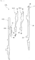
FIG. 6 is a diagram illustrating a configuration of a slider included in a compound needle according to a third embodiment. -
FIG. 7A is a cross-sectional view taken along a line (VII) - (VII) shown inFIG. 6 , andFIG. 7B illustrates the size of an outer cutout portion. -
FIGS. 8 illustrate the vicinity of crimped portions of sliders included in a compound needle according to a fourth embodiment, whereFIG. 8A is an enlarged view of the same region as the region enclosed by dashed-dotted line inFIG. 6 , andFIG. 8B is a cross-sectional view taken along a line (b)-(b) shown inFIG. 8A . -
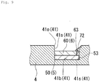
FIG. 9 is a cross-sectional view of the vicinity of a crimped portion, according to another example of the sliders included in the compound needle of the fourth embodiment. - A compound needle 1α according to a first embodiment will be described with reference to
FIGS. 1A, 1B ,2 ,3A, and 3B . The upper and lower sides with respect to the paper plane inFIGS. 1A and 1B ,FIG. 2 , andFIG. 3A are respectively the front and rear sides of the compound needle 1α, the right and left sides with respect to the paper plane are respectively the lower and upper sides of the compound needle 1α, and the depth direction with respect to the paper plane is the thickness direction of the compound needle 1α. InFIG. 3B , the far and near sides with respect to the paper plane are respectively the front and rear sides of the compound needle 1α, the right and left sides with respect to the paper plane are respectively the lower and upper sides of the compound needle 1α, and the vertical direction with respect to the paper plane is the thickness direction of the compound needle 1α. - As shown in
FIGS. 1A, 1B , and2 , the compound needle 1α includes aneedle body 2 that has ahook 20, and aslider 3 that moves relative to theneedle body 2 to open and close thehook 20. The compound needle 1α of the present embodiment can be used in a two-bed flat knitting machine or a four-bed flat knitting machine. The configurations of the compound needle 1α of the first embodiment will be described in detail below. - As shown in
FIGS. 1A, 1B , and2 , theneedle body 2 includes thehook 20 provided at a leading end, and aslider groove 21 formed in an upper face on the leading end side. Blades (aninner blade 5 and an outer blade 6) of the later-describedslider 3 are slidably fitted into the slider groove 21 (seeFIGS. 1A and 1B ). The slider 3 (theinner blade 5 and the outer blade 6) slides with respect to theneedle body 2 to open and close thehook 20. The open/close operation of thehook 20 will be described in detail later when theinner blade 5 and theouter blade 6 are described. Theneedle body 2 has, on the upper face on the rear end side, an engagingportion 22 that protrudes upward so as to abut against theslider 3, and defines the retraction limit position when theslider 3 slides. - As shown in
FIGS. 1A, 1B , and2 , theslider 3 includes aslider body 4, and theinner blade 5 and theouter blade 6 that are mounted on theslider body 4. As shown inFIGS. 3A and 3B , theinner blade 5 and theouter blade 6 are fixed to theslider body 4 with crimpedportions 7, which are formed by crimping the surface of theslider body 4. InFIG. 3A , for convenience of description, regions in which thecrimped portions 7 are provided are schematically shown by hatched rectangles. - As shown in
FIGS. 1A, 1B ,2 ,3A, and 3B , theslider body 4 includes acoupling portion 40 that protrudes downward from the lower face thereof. Thecoupling portion 40 has a certain length in a longitudinal direction of theslider body 4. Theslider body 4 has afitting groove 41 that is formed in a side surface (surface on the near side with respect to the paper plane ofFIGS. 1A, 1B , and2 ) of thecoupling portion 40, thefitting groove 41 extending in the longitudinal direction of thecoupling portion 40. By being fitted into thefitting groove 41, the later-describedinner blade 5 and theouter blade 6 are coupled to theslider body 4. As shown inFIG. 3B , thefitting groove 41 includes a bottom 41b, andwall sides 41s, which extend in the longitudinal direction of theslider body 4 and are perpendicular to the bottom 41b, and thefitting groove 41 has an opening 41o on the side opposite to the bottom 41b. In the present embodiment, as shown inFIGS. 1A, 1B , and2 , theslider body 4 includes arecess 410 that is recessed from thefitting groove 41 to the upper side of theslider body 4. In the present embodiment, therecess 410 is a through hole that penetrates theslider body 4 in the thickness direction. The rear end portion of thecoupling portion 40 of theslider body 4 serves as an engaging portion 42 (seeFIG. 1 ) that abuts against the engagingportion 22 of theneedle body 2 when theslider 3 slides into the rear end position. - As shown in
FIG. 2 , theinner blade 5 and theouter blade 6 are laminar members that have substantially the same outer shape. Theinner blade 5 and theouter blade 6 respectively have an innerfitting region 50 and an outerfitting region 60, which are fitted into thefitting groove 41 of theslider body 4. As shown inFIGS. 3A and 3B , theinner blade 5 and theouter blade 6 are fitted into thefitting groove 41 while overlapping each other so that the innerfitting region 50 of theinner blade 5 is positioned on the bottom 41b side of thefitting groove 41 and the outerfitting region 60 of theouter blade 6 is positioned on the opening 41o side of thefitting groove 41. - As shown in
FIG. 2 , theinner blade 5 includes atongue 5t that is provided at the leading end and on which a stitch is held when the stitch is transferred, and the innerfitting region 50 that is provided at the rear end and is fitted into thefitting groove 41. A lower end face, on the leading end side, of theinner blade 5 is fitted into theslider groove 21 of theneedle body 2. In the present embodiment, theinner blade 5 has a protrudingportion 52 that protrudes from the innerfitting region 50 to the upper side of theinner blade 5. The protrudingportion 52 is fitted into therecess 410 of theslider body 4. In other words, as a result of the protrudingportion 52 being fitted into therecess 410 and the innerfitting region 50 being fitted into thefitting groove 41, theinner blade 5 is positioned with respect to theslider body 4. - The
outer blade 6 also includes, as with theinner blade 5, atongue 6t that is provided at a leading end and on which a stitch is held when the stitch is transferred, and the outerfitting region 60 that is provided at a rear end and is fitted into the fitting groove 41 (seeFIG. 2 ). A lower end face, on the leading end side, of theouter blade 6 is fitted into theslider groove 21 of theneedle body 2. In the present embodiment, theouter blade 6 has a protrudingportion 62 that protrudes from the outerfitting region 60 to the upper side of theouter blade 6. The protrudingportion 62 is fitted into therecess 410 of theslider body 4. In other words, as a result of the protrudingportion 62 being fitted into therecess 410 and the outerfitting region 60 being fitted into thefitting groove 41, theouter blade 6 is positioned with respect to theslider body 4. - The
inner blade 5 is longer in the longitudinal direction than theouter blade 6. More specifically, the innerfitting region 50 is longer than the outerfitting region 60. As a result of theinner blade 5 being longer in the longitudinal direction than theouter blade 6, the innerfitting region 50 of theinner blade 5 has an exposedregion 51 whose surface is exposed to the outside (seeFIGS. 1A, 1B , and3A ) . The longitudinal length of theinner blade 5 can be selected as appropriate such that later-described innercrimped portions 72 can be formed in the exposedregion 51. For example, the longitudinal length of the innerfitting region 50 may be at least 1.2 times and at most 3.0 times as large as the length of the outerfitting region 60. - As shown in
FIG. 1A , when theslider 3 is advanced forward with respect to theneedle body 2, theinner blade 5 and theouter blade 6 sandwich the leading end portion of thehook 20 to close thehook 20. On the other hand, as shown inFIG. 1B , when theslider 3 is retracted with respect to theneedle body 2, the lower end faces on the leading end side of theinner blade 5 and theouter blade 6 are retracted within theslider groove 21 of theneedle body 2. When theslider 3 is completely retracted, the engagingportion 42 of theslider body 4 abuts against the engagingportion 22 of theneedle body 2, and is positioned at the retraction limit position of theslider 3. - The
crimped portions 7 fix theinner blade 5 and theouter blade 6 to theslider body 4. Thecrimped portions 7 are constituted by the constituent material of theslider body 4 that was plastically deformed through crimping. Thecrimped portions 7 bulge inward of thefitting groove 41 from theslider body 4. - In the present embodiment, as shown in
FIG. 3A , thecrimpedportions 7 include three outercrimped portions 71 in a region in which theinner blade 5 and theouter blade 6 overlap each other, and two innercrimped portions 72 in the exposedregion 51 of theinner blade 5. Of the three outercrimped portions 71, two are provided in edge portions of the protrudingportion 62 of theouter blade 6 that are opposite to each other in the front-rear direction, and one is provided in a lower edge portion of the outerfitting region 60 that is opposite to the protrudingportion 62 with respect to the protruding direction thereof. The outercrimped portions 71 are formed bulging inward of thefitting groove 41 from theslider body 4 to cover the surfaces of the edge portions of the outerfitting region 60. The innercrimped portions 72 are provided respectively in the lower edge portion and the upper edge portion of the exposedregion 51. In the present embodiment, the crimpedportion 72 provided on the lower side of the exposedregion 51 and the crimpedportion 72 provided on the upper side thereof are provided at positions opposite to each other. As shown inFIG. 3B , the inner crimpedportions 72 are formed bulging inward of thefitting groove 41 from theslider body 4 to cover the surfaces of the edge portions of the exposedregion 51. - Since the
inner blade 5 has the exposedregion 51 that is formed by theinner blade 5 being longer than theouter blade 6, and thus the inner crimpedportions 72 are formed to cover the exposed region 51 (inner fitting region 50), it is possible to directly fix theinner blade 5 to theslider body 4. As a result of theinner blade 5 including the exposedregion 51, it is possible to enhance the degree of freedom of the positions and the number of the crimped portions, depending on the difference in length between theinner blade 5 and theouter blade 6. For example, a plurality of inner crimpedportions 72 may be provided on each of the lower and upper sides of the exposedregion 51. Note that theouter blade 6 can be directly fixed to theslider body 4 by the outercrimped portions 71. As described above, in the compound needle 1α according to the present embodiment, both theinner blade 5 and theouter blade 6 are directly fixed to theslider body 4 using the crimpedportions 7, and thus, even if a moment is continuously applied to a boundary portion between theslider body 4 and the two blades (theinner blade 5 and the outer blade 6), it is possible to prevent theslider body 4 and the two blades from becoming loose with time. - A compound needle 1β according to a second embodiment will be described with reference to
FIGS. 4 ,5A, and 5B . The views inFIGS. 4 and5B are similar to those ofFIGS. 1 and3A in the first embodiment, and the view ofFIG. 5A is similar to that ofFIG. 3B . Configurations inFIGS. 4 ,5A, and 5B that have functions similar to those of the first embodiment are denoted by the same reference signs as in the first embodiment. The following description in the present embodiment focuses on differences from the first embodiment. - A main difference between the compound needle 1β of the present embodiment and the compound needle 1α of the first embodiment is that the exposed
region 51 hasrear cutout portions 54. Therear cutout portions 54 have a size such that part of the bottom 41b of thefitting groove 41 can be exposed therethrough. As a result of providing therear cutout portions 54, spaces are each formed by thewall side 41s of thefitting groove 41, the bottom 41b of thefitting groove 41, and a face (side face) of the exposedregion 51 that faces thewall side 41s, in a state in which nocrimpedportion 72 is present. The constituent material of theslider body 4 that is subject to plastic deformation enters the spaces, and innercrimped portions 72 are formed in the spaces. - The size of the
rear cutout portions 54 can be selected as appropriate such that theinner blade 5 can be fixed using the inner crimpedportions 72 provided in therear cutout portions 54. For example, a length L1 of therear cutout portion 54, which is the largest length in the vertical direction of theinner blade 5, may be at least 0.1 times and at most 0.3 times as large as a length W in the vertical direction of the inner blade 5 (seeFIG. 5B ). Furthermore, a length L2 of therear cutout portion 54, which is the largest length in the front-rear direction of theinner blade 5, may be at least 1 time and at most 10 times as large as the vertical length L1 of therear cutout portion 54. These measures prevent the formation of therear cutout portions 54 from reducing the strength of theinner blade 5. The shape of therear cutout portions 54 can be selected as appropriate such that the inner crimpedportions 72 can be formed in an exposed part of the bottom 41b of thefitting groove 41, and the inner crimpedportions 72 can press against the side faces (faces along the thickness direction of the inner blade 5) of the innerfitting region 50. For example, therear cutout portions 54 may be rectangular, arc-like, or the like when viewed from above. - In the present embodiment, as shown in
FIG. 4 , onerear cutout portion 54 is provided in each of the lower and upper edge portions of the exposedregion 51, but the positions and the number ofrear cutout portions 54 to be formed can be selected as appropriate. For example, a plurality ofrear cutout portions 54 may be provided on each of the lower and upper sides of the exposedregion 51. - As a result of providing the
rear cutout portions 54 in the exposedregion 51, as shown inFIG. 5A , the inner crimpedportions 72 cover the surface of the exposed region 51 (inner fitting region 50) and support the side faces of the innerfitting region 50, and thus it is possible to fix theinner blade 5 to theslider body 4 directly and more rigidly. - A compound needle 1γ according to a third embodiment will be described with reference to
FIGS. 6 ,7A, and 7B . The views inFIGS. 6 and7B are similar to those ofFIGS. 1 and3A in the first embodiment, and the view ofFIG. 7A is similar to that ofFIG. 3B . Configurations inFIGS. 6 ,7A, and 7B that have functions similar to those of the first embodiment are denoted by the same reference signs as in the first embodiment. The following description in the present embodiment focuses on differences from the first embodiment. - A main difference between the compound needle 1γ of the present embodiment and the compound needle 1α of the first embodiment is that the
inner blade 5 and theouter blade 6 have substantially the same length, and the outerfitting region 60 of theouter blade 6 includes anouter cutout portion 63. As shown inFIG. 6 , theouter cutout portion 63 has a size such that, when theinner blade 5 and theouter blade 6 are laid overlapping each other, part of the surface of the innerfitting region 50 of theinner blade 5 can be exposed from theouter cutout portion 63 to the outside. As a result of providing theouter cutout portion 63, a space is formed by thewall side 41s of thefitting groove 41, the surface of the innerfitting region 50, and the face (side face) of the outerfitting region 60 that faces thewall side 41s, in a state in which no crimpedportion 72 is present. An inner crimpedportion 72 is formed in this space. - The size of the
outer cutout portion 63 can be selected as appropriate such that a tool for forming an inner crimpedportion 72 can be placed in the exposed part of the innerfitting region 50. For example, a length L3 of theouter cutout portion 63, which is the largest length in the vertical direction of theouter blade 6, may be at least 0.07 times and at most 0.5 times as large as the length W in the vertical direction of the outer blade 6 (FIG. 7B ) . Furthermore, a length L4 of theouter cutout portion 63, which is the largest length in the front-rear direction of theouter blade 6, may be at least 1 time and at most 10 times as large as the length L3 of theouter cutout portion 63, which is the largest length in the vertical direction of theouter blade 6. These measures prevent the formation of theouter cutout portion 63 from reducing the strength of theouter blade 6. The shape of theouter cutout portion 63 can be selected as appropriate such that the inner crimpedportion 72 can be formed in the exposed part of the innerfitting region 50. For example, theouter cutout portion 63 may be rectangular, arc-like, or the like when viewed from above. - In the present embodiment, as shown in
FIG. 6 , oneouter cutout portion 63 is provided in the lower rear edge portion of the outerfitting region 60, but the positions and the number ofouter cutout portions 63 to be formed can be selected as appropriate. For example, anouter cutout portion 63 may be provided in the front edge portion of the outerfitting region 60 or in the upper edge portion of the outerfitting region 60. Furthermore, a plurality ofouter cutout portions 63 may be provided in the outerfitting region 60. - In the present embodiment, as shown in
FIG. 6 , thecrimped portions 7 include threeouter crimpedportions 71 in the vicinity of the protrudingportion 52 of theinner blade 5 and the protrudingportion 62 of theouter blade 6, and one inner crimpedportion 72 in the vicinity of theouter cutout portion 63. Of the three outercrimped portions 71, two are provided in the edge portions of the protrudingportion 62 of theouter blade 6 that are opposite to each other in the front-rear direction, and one is provided in the lower edge portion of the outerfitting region 60 that is opposite to the protrudingportion 62 in the protruding direction thereof. The region in which the outercrimped portions 71 are formed includes no outer cutout portion. Accordingly, the outercrimped portions 71 are formed bulging inward of thefitting groove 41 from theslider body 4 so as to cover the edge surfaces of theouter blade 6. On the other hand, in the region in which the inner crimpedportion 72 is formed, the outerfitting region 60 includes theouter cutout portion 63. Accordingly, the inner crimpedportion 72 enters theouter cutout portion 63, and bulges inward of thefitting groove 41 from theslider body 4 so as to cover the surface of the innerfitting region 50. Note that the inner crimpedportion 72 may enter theouter cutout portion 63, and bulge toward the edge portion of theouter cutout portion 63 so as to cover the surface of the innerfitting region 50 and the edge surface of the outerfitting region 60. As a result of the inner crimpedportion 72 covering the surface of the outerfitting region 60 as well, the inner crimpedportion 72 can rigidly fix both theinner blade 5 and theouter blade 6 to theslider body 4. - Since the outer
fitting region 60 includes theouter cutout portion 63, and thus the inner crimpedportion 72 covers the surface of the innerfitting region 50, theinner blade 5 can be directly fixed to theslider body 4. Note that theouter blade 6 can be directly fixed to theslider body 4 by the outercrimped portions 71, regardless of whether or not there is theouter cutout portion 63. - A compound needle 1δ according to a fourth embodiment will be described with reference to
FIGS. 8A, 8B , and9 . The view ofFIG. 8A is similar to that ofFIG. 6 in the third embodiment, and the view ofFIGS. 8B , and9 are similar to that ofFIG. 7A . Configurations inFIGS. 8A, 8B , and9 that have functions similar to those of the third embodiment are denoted by the same reference signs as in the third embodiment. The following description in the present embodiment focuses on differences from the third embodiment. - A main difference between the compound needle 1δ of the present embodiment and the compound needle 1γ of the third embodiment is that the
inner blade 5 has aninner cutout portion 53. Theinner cutout portion 53 is provided at a position in the innerfitting region 50 that corresponds to theouter cutout portion 63, and has a size such that, when theinner blade 5 and theouter blade 6 are laid overlapping each other and are fitted into thefitting groove 41, part of the bottom 41b of thefitting groove 41 can be exposed from theinner cutout portion 53 to the outside. As a result of providing theinner cutout portion 53, a space is formed by thewall side 41s of thefitting groove 41, the bottom 41b of thefitting groove 41, and the face (side face) of the innerfitting region 50 that faces thewall side 41s, in a state in which no inner crimpedportion 72 is present. The constituent material of theslider body 4 that is subject to plastic deformation enters this space via theouter cutout portion 63, and an inner crimpedportion 72 is formed. - The size of the
inner cutout portion 53 can be selected as appropriate such that theinner cutout portion 53 is smaller than theouter cutout portion 63 and theinner blade 5 can be fixed using the inner crimpedportion 72 provided in theinner cutout portion 53. For example, theinner cutout portion 53 may have a plan view area that is at least 0.01 times and at most 0.2 times as large as the plan view area of theouter cutout portion 63. With this measure, steps are formed between the bottom 41b of thefitting groove 41, the surface of the innerfitting region 50, and the surface of the outerfitting region 60, and part of the bottom 41b of thefitting groove 41 and part of the surface of the innerfitting region 50 can be exposed to the outside. The shape of theinner cutout portion 53 can be selected as appropriate such that the inner crimpedportion 72 can be formed in an exposed part of the bottom 41b of thefitting groove 41, and the inner crimpedportion 72 can press against the side face (face along the thickness direction of the inner blade 5) of the innerfitting region 50. For example, theinner cutout portion 53 may be rectangular, arc-like, or the like when viewed from above. - The inner crimped
portion 72 enters theouter cutout portion 63 and enters theinner cutout portion 53, thereby covering the surface of the innerfitting region 50, and is provided in the space formed by the bottom 41b and thewall side 41s of thefitting groove 41, and the side face (face along the thickness direction of the inner blade 5) of the innerfitting region 50. At this time, the inner crimpedportion 72 may also be formed without covering the edge surface of the outerfitting region 60 as shown inFIG. 8B , or may also be formed while covering the edge surface of the outerfitting region 60 as shown inFIG. 9 . - As a result of providing, in addition to the
outer cutout portion 63, theinner cutout portion 53, the inner crimpedportion 72 not only covers the surface of the innerfitting region 50 but also supports the side face of the innerfitting region 50, thus making it possible to fix theinner blade 5 to theslider body 4 directly and more rigidly. Furthermore, if the inner crimpedportion 72 covers the surface of the outerfitting region 60 as well, theinner blade 5 and theouter blade 6 can be integrated, and can be directly and more rigidly fixed to theslider body 4. - Crimping of the slider body can also be performed on a face in which no fitting groove is formed (hereinafter, referred to as a reverse face). Assume that, in the inner fitting region, two faces, in a cross-section, that are opposite to each other in the thickness direction are referred to as a front face and a reverse face, and two faces that connect the front face and the reverse face are respectively referred to as side faces, the inner fitting region may have a rounded apex that is constituted by the front face or the reverse face and a side face. If the inner fitting region is fitted into the fitting groove so that the rounded apex is located on the bottom side of the fitting groove, a space may be formed by the wall side of the fitting groove, the bottom of the fitting groove, and the rounded apex of the inner fitting region. Therefore, by crimping the reverse face of the slider body toward this space, the constituent material on the bottom side of the slider body plastically deforms and reaches the substantially triangular region that conforms to the rounded apex, and thus it is possible to fill the space with the crimped portion.
Claims (5)
- A compound needle (1α) comprising:a needle body (2) that has a hook (20), anda slider (3) configured to move relative to the needle body (2) to open and close the hook (20), the slider (3) characterized by:a slider body (4) that has a fitting groove (41) formed in a longitudinal direction of the slider body (4);an inner blade (5) that is laminar, and has an inner fitting region (50) that is fitted into the fitting groove (41) and positioned on a bottom (41b) side of the fitting groove (41);an outer blade (6) that is laminar, and has an outer fitting region (60) that is fitted into the fitting groove (41) and positioned on an opening (41o) side of the fitting groove (41), the outer blade (6) being laid overlapping a surface of the inner blade (5) with part of a surface of the inner fitting region (50) exposed to the outside; anda crimped portion (7) that is constituted by a constituent material of the slider body (4) that was plastically deformed through crimping, andthe crimped portion (7) includes:an inner crimped portion (72) that covers at least part of the exposed part of the inner fitting region (50); andan outer crimped portion (71) that covers part of a surface of the outer fitting region (60).
- The compound needle according to claim 1,
wherein the inner blade (5) is longer in a longitudinal direction than the outer blade (6), and includes an exposed region (51) that is formed by the part of the surface of the inner fitting region (50) that is exposed to the outside. - The compound needle according to claim 2,
wherein the inner blade (5) includes, in the exposed region (51), a rear cutout portion (54) from which part of the bottom (41b) of the fitting groove (41) is exposed. - The compound needle according to any one of claims 1 to 3,
wherein the outer blade (6) includes, in the outer fitting region (60), an outer cutout portion (63) from which part of the surface of the inner fitting region (50) is exposed to the outside. - The compound needle according to claim 4,
wherein the inner blade (5) includes, at a position in the inner fitting region (50) that corresponds to the outer cutout portion (63), an inner cutout portion (53) from which part of the bottom (41b) of the fitting groove (41) is exposed to the outside.
Applications Claiming Priority (1)
| Application Number | Priority Date | Filing Date | Title |
|---|---|---|---|
| JP2017239441A JP6718856B2 (en) | 2017-12-14 | 2017-12-14 | Compound needle |
Publications (2)
| Publication Number | Publication Date |
|---|---|
| EP3498903A1 true EP3498903A1 (en) | 2019-06-19 |
| EP3498903B1 EP3498903B1 (en) | 2022-05-18 |
Family
ID=64665450
Family Applications (1)
| Application Number | Title | Priority Date | Filing Date |
|---|---|---|---|
| EP18212359.6A Active EP3498903B1 (en) | 2017-12-14 | 2018-12-13 | Compound needle |
Country Status (4)
| Country | Link |
|---|---|
| EP (1) | EP3498903B1 (en) |
| JP (1) | JP6718856B2 (en) |
| KR (1) | KR102168784B1 (en) |
| CN (1) | CN109957881B (en) |
Families Citing this family (1)
| Publication number | Priority date | Publication date | Assignee | Title |
|---|---|---|---|---|
| EP3904578B1 (en) * | 2020-04-29 | 2024-11-06 | Groz-Beckert KG | Compound needle for knitting machines |
Citations (3)
| Publication number | Priority date | Publication date | Assignee | Title |
|---|---|---|---|---|
| JP2946323B2 (en) | 1997-05-01 | 1999-09-06 | 株式会社島精機製作所 | Composite needle of flat knitting machine |
| EP1333116A1 (en) * | 2000-10-20 | 2003-08-06 | Shima Seiki Mfg., Ltd | Composite needle |
| DE102015105648A1 (en) * | 2015-04-14 | 2016-10-20 | Groz-Beckert Kg | Slide spring, slide, slide needle, guide arrangement and method for producing at least one slide spring |
Family Cites Families (12)
| Publication number | Priority date | Publication date | Assignee | Title |
|---|---|---|---|---|
| GB1283027A (en) * | 1970-02-18 | 1972-07-26 | Vittorio Setton | Improvements in or relating to needles |
| DD156331A3 (en) * | 1980-10-08 | 1982-08-18 | Heinz Lindner | MESH-CONTROLLED SLIDE NEEDLE FOR ACTIVE AND KNITTING MACHINES |
| DE4331940C1 (en) * | 1993-09-21 | 1994-12-15 | Groz & Soehne Theodor | Transferring needle |
| DE4430705A1 (en) * | 1994-08-30 | 1996-03-07 | Scheller Gmbh | Knitting machine |
| AU2003289227A1 (en) * | 2002-12-20 | 2004-07-14 | Shima Seiki Manufacturing, Ltd. | Compound needle |
| JP5732316B2 (en) * | 2010-06-18 | 2015-06-10 | 株式会社島精機製作所 | Compound needle of flat knitting machine |
| JP5766430B2 (en) | 2010-11-22 | 2015-08-19 | 株式会社島精機製作所 | Compound needle of flat knitting machine |
| JP2013067878A (en) | 2011-09-21 | 2013-04-18 | Shima Seiki Mfg Ltd | Compound needle |
| JP5875347B2 (en) * | 2011-11-30 | 2016-03-02 | 株式会社島精機製作所 | Compound needle of flat knitting machine |
| JP2013241698A (en) * | 2012-05-21 | 2013-12-05 | Shima Seiki Mfg Ltd | Compound needle of flat knitting machine |
| JP2014065987A (en) * | 2012-09-25 | 2014-04-17 | Shima Seiki Mfg Ltd | Composite needle of flat-knitting machine |
| CN103334223A (en) * | 2013-07-04 | 2013-10-02 | 宁波慈星股份有限公司 | Knitting needle for flat knitting machine |
-
2017
- 2017-12-14 JP JP2017239441A patent/JP6718856B2/en active Active
-
2018
- 2018-12-12 KR KR1020180159786A patent/KR102168784B1/en active Active
- 2018-12-13 EP EP18212359.6A patent/EP3498903B1/en active Active
- 2018-12-14 CN CN201811528019.8A patent/CN109957881B/en active Active
Patent Citations (3)
| Publication number | Priority date | Publication date | Assignee | Title |
|---|---|---|---|---|
| JP2946323B2 (en) | 1997-05-01 | 1999-09-06 | 株式会社島精機製作所 | Composite needle of flat knitting machine |
| EP1333116A1 (en) * | 2000-10-20 | 2003-08-06 | Shima Seiki Mfg., Ltd | Composite needle |
| DE102015105648A1 (en) * | 2015-04-14 | 2016-10-20 | Groz-Beckert Kg | Slide spring, slide, slide needle, guide arrangement and method for producing at least one slide spring |
Also Published As
| Publication number | Publication date |
|---|---|
| CN109957881A (en) | 2019-07-02 |
| EP3498903B1 (en) | 2022-05-18 |
| KR102168784B1 (en) | 2020-10-22 |
| CN109957881B (en) | 2020-08-25 |
| KR20190071603A (en) | 2019-06-24 |
| JP2019105011A (en) | 2019-06-27 |
| JP6718856B2 (en) | 2020-07-08 |
Similar Documents
| Publication | Publication Date | Title |
|---|---|---|
| EP2564720A1 (en) | Metal double-sided tooth and slide fastener | |
| US20150101862A1 (en) | Electrical connection box | |
| JPWO2009128136A1 (en) | Metal single face teeth and double swing slide fasteners | |
| CN105491916A (en) | Clamps and Fixing Wires | |
| JPWO2011151882A1 (en) | Slide fastener | |
| EP3498903B1 (en) | Compound needle | |
| US8991017B2 (en) | Slider for slide fastener | |
| US9776480B2 (en) | Door frame | |
| CN103068271A (en) | Invisible zipper | |
| US11285889B2 (en) | Harness guide | |
| EP2397589B1 (en) | Compound needle for flatbed knitting machine | |
| JP2018514657A (en) | Slide spring, slider, slide needle, guide structure, and method for creating at least one slide spring | |
| CN104097604B (en) | through anchor | |
| JP3194534U (en) | Slide fastener fasteners and slide fasteners using fasteners | |
| JP6451256B2 (en) | Binding device | |
| JP2008308811A (en) | Compound needle with flanged slider channel | |
| JP3164407U (en) | Slide fastener fastener | |
| JP6982093B2 (en) | Slider for slide fastener | |
| JP2013241698A (en) | Compound needle of flat knitting machine | |
| JP6692325B2 (en) | Compound needle | |
| JP5065990B2 (en) | Corner structure of assembly-type case | |
| CN114641219B (en) | zipper | |
| JP2012025324A (en) | Body structure for railway vehicle | |
| JP2015020692A (en) | Vehicle door structure | |
| JP2008143385A (en) | Panel slider of shift lever device |
Legal Events
| Date | Code | Title | Description |
|---|---|---|---|
| PUAI | Public reference made under article 153(3) epc to a published international application that has entered the european phase |
Free format text: ORIGINAL CODE: 0009012 |
|
| STAA | Information on the status of an ep patent application or granted ep patent |
Free format text: STATUS: THE APPLICATION HAS BEEN PUBLISHED |
|
| AK | Designated contracting states |
Kind code of ref document: A1 Designated state(s): AL AT BE BG CH CY CZ DE DK EE ES FI FR GB GR HR HU IE IS IT LI LT LU LV MC MK MT NL NO PL PT RO RS SE SI SK SM TR |
|
| AX | Request for extension of the european patent |
Extension state: BA ME |
|
| STAA | Information on the status of an ep patent application or granted ep patent |
Free format text: STATUS: REQUEST FOR EXAMINATION WAS MADE |
|
| 17P | Request for examination filed |
Effective date: 20191213 |
|
| RBV | Designated contracting states (corrected) |
Designated state(s): AL AT BE BG CH CY CZ DE DK EE ES FI FR GB GR HR HU IE IS IT LI LT LU LV MC MK MT NL NO PL PT RO RS SE SI SK SM TR |
|
| RIC1 | Information provided on ipc code assigned before grant |
Ipc: D04B 35/06 20060101AFI20211103BHEP |
|
| GRAP | Despatch of communication of intention to grant a patent |
Free format text: ORIGINAL CODE: EPIDOSNIGR1 |
|
| STAA | Information on the status of an ep patent application or granted ep patent |
Free format text: STATUS: GRANT OF PATENT IS INTENDED |
|
| INTG | Intention to grant announced |
Effective date: 20211213 |
|
| GRAS | Grant fee paid |
Free format text: ORIGINAL CODE: EPIDOSNIGR3 |
|
| GRAA | (expected) grant |
Free format text: ORIGINAL CODE: 0009210 |
|
| STAA | Information on the status of an ep patent application or granted ep patent |
Free format text: STATUS: THE PATENT HAS BEEN GRANTED |
|
| AK | Designated contracting states |
Kind code of ref document: B1 Designated state(s): AL AT BE BG CH CY CZ DE DK EE ES FI FR GB GR HR HU IE IS IT LI LT LU LV MC MK MT NL NO PL PT RO RS SE SI SK SM TR |
|
| REG | Reference to a national code |
Ref country code: GB Ref legal event code: FG4D |
|
| REG | Reference to a national code |
Ref country code: CH Ref legal event code: EP |
|
| REG | Reference to a national code |
Ref country code: IE Ref legal event code: FG4D |
|
| REG | Reference to a national code |
Ref country code: DE Ref legal event code: R096 Ref document number: 602018035712 Country of ref document: DE |
|
| REG | Reference to a national code |
Ref country code: AT Ref legal event code: REF Ref document number: 1493223 Country of ref document: AT Kind code of ref document: T Effective date: 20220615 |
|
| REG | Reference to a national code |
Ref country code: LT Ref legal event code: MG9D |
|
| REG | Reference to a national code |
Ref country code: NL Ref legal event code: MP Effective date: 20220518 |
|
| REG | Reference to a national code |
Ref country code: AT Ref legal event code: MK05 Ref document number: 1493223 Country of ref document: AT Kind code of ref document: T Effective date: 20220518 |
|
| PG25 | Lapsed in a contracting state [announced via postgrant information from national office to epo] |
Ref country code: SE Free format text: LAPSE BECAUSE OF FAILURE TO SUBMIT A TRANSLATION OF THE DESCRIPTION OR TO PAY THE FEE WITHIN THE PRESCRIBED TIME-LIMIT Effective date: 20220518 Ref country code: PT Free format text: LAPSE BECAUSE OF FAILURE TO SUBMIT A TRANSLATION OF THE DESCRIPTION OR TO PAY THE FEE WITHIN THE PRESCRIBED TIME-LIMIT Effective date: 20220919 Ref country code: NO Free format text: LAPSE BECAUSE OF FAILURE TO SUBMIT A TRANSLATION OF THE DESCRIPTION OR TO PAY THE FEE WITHIN THE PRESCRIBED TIME-LIMIT Effective date: 20220818 Ref country code: NL Free format text: LAPSE BECAUSE OF FAILURE TO SUBMIT A TRANSLATION OF THE DESCRIPTION OR TO PAY THE FEE WITHIN THE PRESCRIBED TIME-LIMIT Effective date: 20220518 Ref country code: LT Free format text: LAPSE BECAUSE OF FAILURE TO SUBMIT A TRANSLATION OF THE DESCRIPTION OR TO PAY THE FEE WITHIN THE PRESCRIBED TIME-LIMIT Effective date: 20220518 Ref country code: HR Free format text: LAPSE BECAUSE OF FAILURE TO SUBMIT A TRANSLATION OF THE DESCRIPTION OR TO PAY THE FEE WITHIN THE PRESCRIBED TIME-LIMIT Effective date: 20220518 Ref country code: GR Free format text: LAPSE BECAUSE OF FAILURE TO SUBMIT A TRANSLATION OF THE DESCRIPTION OR TO PAY THE FEE WITHIN THE PRESCRIBED TIME-LIMIT Effective date: 20220819 Ref country code: FI Free format text: LAPSE BECAUSE OF FAILURE TO SUBMIT A TRANSLATION OF THE DESCRIPTION OR TO PAY THE FEE WITHIN THE PRESCRIBED TIME-LIMIT Effective date: 20220518 Ref country code: ES Free format text: LAPSE BECAUSE OF FAILURE TO SUBMIT A TRANSLATION OF THE DESCRIPTION OR TO PAY THE FEE WITHIN THE PRESCRIBED TIME-LIMIT Effective date: 20220518 Ref country code: BG Free format text: LAPSE BECAUSE OF FAILURE TO SUBMIT A TRANSLATION OF THE DESCRIPTION OR TO PAY THE FEE WITHIN THE PRESCRIBED TIME-LIMIT Effective date: 20220818 Ref country code: AT Free format text: LAPSE BECAUSE OF FAILURE TO SUBMIT A TRANSLATION OF THE DESCRIPTION OR TO PAY THE FEE WITHIN THE PRESCRIBED TIME-LIMIT Effective date: 20220518 |
|
| PG25 | Lapsed in a contracting state [announced via postgrant information from national office to epo] |
Ref country code: RS Free format text: LAPSE BECAUSE OF FAILURE TO SUBMIT A TRANSLATION OF THE DESCRIPTION OR TO PAY THE FEE WITHIN THE PRESCRIBED TIME-LIMIT Effective date: 20220518 Ref country code: PL Free format text: LAPSE BECAUSE OF FAILURE TO SUBMIT A TRANSLATION OF THE DESCRIPTION OR TO PAY THE FEE WITHIN THE PRESCRIBED TIME-LIMIT Effective date: 20220518 Ref country code: LV Free format text: LAPSE BECAUSE OF FAILURE TO SUBMIT A TRANSLATION OF THE DESCRIPTION OR TO PAY THE FEE WITHIN THE PRESCRIBED TIME-LIMIT Effective date: 20220518 Ref country code: IS Free format text: LAPSE BECAUSE OF FAILURE TO SUBMIT A TRANSLATION OF THE DESCRIPTION OR TO PAY THE FEE WITHIN THE PRESCRIBED TIME-LIMIT Effective date: 20220918 |
|
| PG25 | Lapsed in a contracting state [announced via postgrant information from national office to epo] |
Ref country code: SM Free format text: LAPSE BECAUSE OF FAILURE TO SUBMIT A TRANSLATION OF THE DESCRIPTION OR TO PAY THE FEE WITHIN THE PRESCRIBED TIME-LIMIT Effective date: 20220518 Ref country code: SK Free format text: LAPSE BECAUSE OF FAILURE TO SUBMIT A TRANSLATION OF THE DESCRIPTION OR TO PAY THE FEE WITHIN THE PRESCRIBED TIME-LIMIT Effective date: 20220518 Ref country code: RO Free format text: LAPSE BECAUSE OF FAILURE TO SUBMIT A TRANSLATION OF THE DESCRIPTION OR TO PAY THE FEE WITHIN THE PRESCRIBED TIME-LIMIT Effective date: 20220518 Ref country code: EE Free format text: LAPSE BECAUSE OF FAILURE TO SUBMIT A TRANSLATION OF THE DESCRIPTION OR TO PAY THE FEE WITHIN THE PRESCRIBED TIME-LIMIT Effective date: 20220518 Ref country code: DK Free format text: LAPSE BECAUSE OF FAILURE TO SUBMIT A TRANSLATION OF THE DESCRIPTION OR TO PAY THE FEE WITHIN THE PRESCRIBED TIME-LIMIT Effective date: 20220518 Ref country code: CZ Free format text: LAPSE BECAUSE OF FAILURE TO SUBMIT A TRANSLATION OF THE DESCRIPTION OR TO PAY THE FEE WITHIN THE PRESCRIBED TIME-LIMIT Effective date: 20220518 |
|
| REG | Reference to a national code |
Ref country code: DE Ref legal event code: R097 Ref document number: 602018035712 Country of ref document: DE |
|
| PLBE | No opposition filed within time limit |
Free format text: ORIGINAL CODE: 0009261 |
|
| STAA | Information on the status of an ep patent application or granted ep patent |
Free format text: STATUS: NO OPPOSITION FILED WITHIN TIME LIMIT |
|
| PG25 | Lapsed in a contracting state [announced via postgrant information from national office to epo] |
Ref country code: AL Free format text: LAPSE BECAUSE OF FAILURE TO SUBMIT A TRANSLATION OF THE DESCRIPTION OR TO PAY THE FEE WITHIN THE PRESCRIBED TIME-LIMIT Effective date: 20220518 |
|
| 26N | No opposition filed |
Effective date: 20230221 |
|
| PG25 | Lapsed in a contracting state [announced via postgrant information from national office to epo] |
Ref country code: SI Free format text: LAPSE BECAUSE OF FAILURE TO SUBMIT A TRANSLATION OF THE DESCRIPTION OR TO PAY THE FEE WITHIN THE PRESCRIBED TIME-LIMIT Effective date: 20220518 |
|
| REG | Reference to a national code |
Ref country code: CH Ref legal event code: PL |
|
| GBPC | Gb: european patent ceased through non-payment of renewal fee |
Effective date: 20221213 |
|
| REG | Reference to a national code |
Ref country code: BE Ref legal event code: MM Effective date: 20221231 |
|
| PG25 | Lapsed in a contracting state [announced via postgrant information from national office to epo] |
Ref country code: LU Free format text: LAPSE BECAUSE OF NON-PAYMENT OF DUE FEES Effective date: 20221213 |
|
| PG25 | Lapsed in a contracting state [announced via postgrant information from national office to epo] |
Ref country code: LI Free format text: LAPSE BECAUSE OF NON-PAYMENT OF DUE FEES Effective date: 20221231 Ref country code: IE Free format text: LAPSE BECAUSE OF NON-PAYMENT OF DUE FEES Effective date: 20221213 Ref country code: GB Free format text: LAPSE BECAUSE OF NON-PAYMENT OF DUE FEES Effective date: 20221213 Ref country code: CH Free format text: LAPSE BECAUSE OF NON-PAYMENT OF DUE FEES Effective date: 20221231 |
|
| PG25 | Lapsed in a contracting state [announced via postgrant information from national office to epo] |
Ref country code: FR Free format text: LAPSE BECAUSE OF NON-PAYMENT OF DUE FEES Effective date: 20221231 Ref country code: BE Free format text: LAPSE BECAUSE OF NON-PAYMENT OF DUE FEES Effective date: 20221231 |
|
| PG25 | Lapsed in a contracting state [announced via postgrant information from national office to epo] |
Ref country code: HU Free format text: LAPSE BECAUSE OF FAILURE TO SUBMIT A TRANSLATION OF THE DESCRIPTION OR TO PAY THE FEE WITHIN THE PRESCRIBED TIME-LIMIT; INVALID AB INITIO Effective date: 20181213 |
|
| PG25 | Lapsed in a contracting state [announced via postgrant information from national office to epo] |
Ref country code: CY Free format text: LAPSE BECAUSE OF FAILURE TO SUBMIT A TRANSLATION OF THE DESCRIPTION OR TO PAY THE FEE WITHIN THE PRESCRIBED TIME-LIMIT Effective date: 20220511 |
|
| PG25 | Lapsed in a contracting state [announced via postgrant information from national office to epo] |
Ref country code: MK Free format text: LAPSE BECAUSE OF FAILURE TO SUBMIT A TRANSLATION OF THE DESCRIPTION OR TO PAY THE FEE WITHIN THE PRESCRIBED TIME-LIMIT Effective date: 20220511 |
|
| PG25 | Lapsed in a contracting state [announced via postgrant information from national office to epo] |
Ref country code: MC Free format text: LAPSE BECAUSE OF FAILURE TO SUBMIT A TRANSLATION OF THE DESCRIPTION OR TO PAY THE FEE WITHIN THE PRESCRIBED TIME-LIMIT Effective date: 20220518 |
|
| PG25 | Lapsed in a contracting state [announced via postgrant information from national office to epo] |
Ref country code: TR Free format text: LAPSE BECAUSE OF FAILURE TO SUBMIT A TRANSLATION OF THE DESCRIPTION OR TO PAY THE FEE WITHIN THE PRESCRIBED TIME-LIMIT Effective date: 20220511 Ref country code: MC Free format text: LAPSE BECAUSE OF FAILURE TO SUBMIT A TRANSLATION OF THE DESCRIPTION OR TO PAY THE FEE WITHIN THE PRESCRIBED TIME-LIMIT Effective date: 20220518 |
|
| PG25 | Lapsed in a contracting state [announced via postgrant information from national office to epo] |
Ref country code: MT Free format text: LAPSE BECAUSE OF FAILURE TO SUBMIT A TRANSLATION OF THE DESCRIPTION OR TO PAY THE FEE WITHIN THE PRESCRIBED TIME-LIMIT Effective date: 20220511 |
|
| PG25 | Lapsed in a contracting state [announced via postgrant information from national office to epo] |
Ref country code: BG Free format text: LAPSE BECAUSE OF FAILURE TO SUBMIT A TRANSLATION OF THE DESCRIPTION OR TO PAY THE FEE WITHIN THE PRESCRIBED TIME-LIMIT Effective date: 20220518 |
|
| PG25 | Lapsed in a contracting state [announced via postgrant information from national office to epo] |
Ref country code: BG Free format text: LAPSE BECAUSE OF FAILURE TO SUBMIT A TRANSLATION OF THE DESCRIPTION OR TO PAY THE FEE WITHIN THE PRESCRIBED TIME-LIMIT Effective date: 20220518 |
|
| PGFP | Annual fee paid to national office [announced via postgrant information from national office to epo] |
Ref country code: DE Payment date: 20250930 Year of fee payment: 8 |
|
| PGFP | Annual fee paid to national office [announced via postgrant information from national office to epo] |
Ref country code: IT Payment date: 20251121 Year of fee payment: 8 |