EP3498526A1 - Fahrzeugsitz mit verstelleinrichtung - Google Patents
Fahrzeugsitz mit verstelleinrichtung Download PDFInfo
- Publication number
- EP3498526A1 EP3498526A1 EP18205847.9A EP18205847A EP3498526A1 EP 3498526 A1 EP3498526 A1 EP 3498526A1 EP 18205847 A EP18205847 A EP 18205847A EP 3498526 A1 EP3498526 A1 EP 3498526A1
- Authority
- EP
- European Patent Office
- Prior art keywords
- shaft
- vehicle seat
- axis
- rotation
- seat
- Prior art date
- Legal status (The legal status is an assumption and is not a legal conclusion. Google has not performed a legal analysis and makes no representation as to the accuracy of the status listed.)
- Granted
Links
Images


Classifications
-
- F—MECHANICAL ENGINEERING; LIGHTING; HEATING; WEAPONS; BLASTING
- F16—ENGINEERING ELEMENTS AND UNITS; GENERAL MEASURES FOR PRODUCING AND MAINTAINING EFFECTIVE FUNCTIONING OF MACHINES OR INSTALLATIONS; THERMAL INSULATION IN GENERAL
- F16H—GEARING
- F16H37/00—Combinations of mechanical gearings, not provided for in groups F16H1/00 - F16H35/00
- F16H37/12—Gearings comprising primarily toothed or friction gearing, links or levers, and cams, or members of at least two of these types
-
- B—PERFORMING OPERATIONS; TRANSPORTING
- B60—VEHICLES IN GENERAL
- B60N—SEATS SPECIALLY ADAPTED FOR VEHICLES; VEHICLE PASSENGER ACCOMMODATION NOT OTHERWISE PROVIDED FOR
- B60N2/00—Seats specially adapted for vehicles; Arrangement or mounting of seats in vehicles
- B60N2/02—Seats specially adapted for vehicles; Arrangement or mounting of seats in vehicles the seat or part thereof being movable, e.g. adjustable
- B60N2/04—Seats specially adapted for vehicles; Arrangement or mounting of seats in vehicles the seat or part thereof being movable, e.g. adjustable the whole seat being movable
- B60N2/10—Seats specially adapted for vehicles; Arrangement or mounting of seats in vehicles the seat or part thereof being movable, e.g. adjustable the whole seat being movable tiltable
-
- B—PERFORMING OPERATIONS; TRANSPORTING
- B60—VEHICLES IN GENERAL
- B60N—SEATS SPECIALLY ADAPTED FOR VEHICLES; VEHICLE PASSENGER ACCOMMODATION NOT OTHERWISE PROVIDED FOR
- B60N2/00—Seats specially adapted for vehicles; Arrangement or mounting of seats in vehicles
- B60N2/02—Seats specially adapted for vehicles; Arrangement or mounting of seats in vehicles the seat or part thereof being movable, e.g. adjustable
- B60N2/04—Seats specially adapted for vehicles; Arrangement or mounting of seats in vehicles the seat or part thereof being movable, e.g. adjustable the whole seat being movable
- B60N2/16—Seats specially adapted for vehicles; Arrangement or mounting of seats in vehicles the seat or part thereof being movable, e.g. adjustable the whole seat being movable height-adjustable
- B60N2/1635—Seats specially adapted for vehicles; Arrangement or mounting of seats in vehicles the seat or part thereof being movable, e.g. adjustable the whole seat being movable height-adjustable characterised by the drive mechanism
- B60N2/164—Linear actuator, e.g. screw mechanism
-
- B—PERFORMING OPERATIONS; TRANSPORTING
- B60—VEHICLES IN GENERAL
- B60N—SEATS SPECIALLY ADAPTED FOR VEHICLES; VEHICLE PASSENGER ACCOMMODATION NOT OTHERWISE PROVIDED FOR
- B60N2/00—Seats specially adapted for vehicles; Arrangement or mounting of seats in vehicles
- B60N2/02—Seats specially adapted for vehicles; Arrangement or mounting of seats in vehicles the seat or part thereof being movable, e.g. adjustable
- B60N2/04—Seats specially adapted for vehicles; Arrangement or mounting of seats in vehicles the seat or part thereof being movable, e.g. adjustable the whole seat being movable
- B60N2/16—Seats specially adapted for vehicles; Arrangement or mounting of seats in vehicles the seat or part thereof being movable, e.g. adjustable the whole seat being movable height-adjustable
- B60N2/18—Seats specially adapted for vehicles; Arrangement or mounting of seats in vehicles the seat or part thereof being movable, e.g. adjustable the whole seat being movable height-adjustable the front or the rear portion of the seat being adjustable, e.g. independently of each other
- B60N2/1807—Seats specially adapted for vehicles; Arrangement or mounting of seats in vehicles the seat or part thereof being movable, e.g. adjustable the whole seat being movable height-adjustable the front or the rear portion of the seat being adjustable, e.g. independently of each other characterised by the cinematic
- B60N2/1842—Seats specially adapted for vehicles; Arrangement or mounting of seats in vehicles the seat or part thereof being movable, e.g. adjustable the whole seat being movable height-adjustable the front or the rear portion of the seat being adjustable, e.g. independently of each other characterised by the cinematic pivoting about an axis located in the rear
-
- B—PERFORMING OPERATIONS; TRANSPORTING
- B60—VEHICLES IN GENERAL
- B60N—SEATS SPECIALLY ADAPTED FOR VEHICLES; VEHICLE PASSENGER ACCOMMODATION NOT OTHERWISE PROVIDED FOR
- B60N2/00—Seats specially adapted for vehicles; Arrangement or mounting of seats in vehicles
- B60N2/24—Seats specially adapted for vehicles; Arrangement or mounting of seats in vehicles for particular purposes or particular vehicles
-
- B—PERFORMING OPERATIONS; TRANSPORTING
- B60—VEHICLES IN GENERAL
- B60N—SEATS SPECIALLY ADAPTED FOR VEHICLES; VEHICLE PASSENGER ACCOMMODATION NOT OTHERWISE PROVIDED FOR
- B60N2/00—Seats specially adapted for vehicles; Arrangement or mounting of seats in vehicles
- B60N2/24—Seats specially adapted for vehicles; Arrangement or mounting of seats in vehicles for particular purposes or particular vehicles
- B60N2/38—Seats specially adapted for vehicles; Arrangement or mounting of seats in vehicles for particular purposes or particular vehicles specially constructed for use on tractors or like off-road vehicles
-
- B—PERFORMING OPERATIONS; TRANSPORTING
- B60—VEHICLES IN GENERAL
- B60N—SEATS SPECIALLY ADAPTED FOR VEHICLES; VEHICLE PASSENGER ACCOMMODATION NOT OTHERWISE PROVIDED FOR
- B60N2/00—Seats specially adapted for vehicles; Arrangement or mounting of seats in vehicles
- B60N2/75—Arm-rests
- B60N2/763—Arm-rests adjustable
- B60N2/767—Angle adjustment
-
- B—PERFORMING OPERATIONS; TRANSPORTING
- B60—VEHICLES IN GENERAL
- B60N—SEATS SPECIALLY ADAPTED FOR VEHICLES; VEHICLE PASSENGER ACCOMMODATION NOT OTHERWISE PROVIDED FOR
- B60N2/00—Seats specially adapted for vehicles; Arrangement or mounting of seats in vehicles
- B60N2/75—Arm-rests
- B60N2/763—Arm-rests adjustable
- B60N2/77—Height adjustment
-
- B—PERFORMING OPERATIONS; TRANSPORTING
- B60—VEHICLES IN GENERAL
- B60N—SEATS SPECIALLY ADAPTED FOR VEHICLES; VEHICLE PASSENGER ACCOMMODATION NOT OTHERWISE PROVIDED FOR
- B60N2/00—Seats specially adapted for vehicles; Arrangement or mounting of seats in vehicles
- B60N2/75—Arm-rests
- B60N2/79—Adaptations for additional use of the arm-rests
- B60N2/797—Adaptations for additional use of the arm-rests for use as electrical control means, e.g. switches
-
- F—MECHANICAL ENGINEERING; LIGHTING; HEATING; WEAPONS; BLASTING
- F16—ENGINEERING ELEMENTS AND UNITS; GENERAL MEASURES FOR PRODUCING AND MAINTAINING EFFECTIVE FUNCTIONING OF MACHINES OR INSTALLATIONS; THERMAL INSULATION IN GENERAL
- F16H—GEARING
- F16H21/00—Gearings comprising primarily only links or levers, with or without slides
- F16H21/10—Gearings comprising primarily only links or levers, with or without slides all movement being in, or parallel to, a single plane
- F16H21/44—Gearings comprising primarily only links or levers, with or without slides all movement being in, or parallel to, a single plane for conveying or interconverting oscillating or reciprocating motions
-
- F—MECHANICAL ENGINEERING; LIGHTING; HEATING; WEAPONS; BLASTING
- F16—ENGINEERING ELEMENTS AND UNITS; GENERAL MEASURES FOR PRODUCING AND MAINTAINING EFFECTIVE FUNCTIONING OF MACHINES OR INSTALLATIONS; THERMAL INSULATION IN GENERAL
- F16H—GEARING
- F16H25/00—Gearings comprising primarily only cams, cam-followers and screw-and-nut mechanisms
- F16H25/18—Gearings comprising primarily only cams, cam-followers and screw-and-nut mechanisms for conveying or interconverting oscillating or reciprocating motions
- F16H25/20—Screw mechanisms
Definitions
- the invention relates to a vehicle seat with at least one laterally arranged operating device for operating vehicle seat and / or vehicle functions and an adjusting device for adjusting a vertical position and / or a degree of inclination of the at least one operating device relative to a remainder of the vehicle seat, the adjusting device extending in the seat width direction Rotary axis and connected to the operating device shaft, which is spaced from the axis of rotation and is arranged pivotable about the axis of rotation together with the operating device comprises.
- control devices include, for example, a kind of joystick and other controls such as buttons or switches and thus offer the driver or user, for example, the ability to adjust elements such as the vehicle seat and / or arranged on a vehicle seat associated vehicle elements such as an excavator bucket to move and / or activate.
- these controls are mechanically at least partially decoupled from adjusting the seat for height and / or longitudinal position of the seat and arranged, for example, laterally on the seat. If an operator now sits down on the seat and has to adjust the height of the seat, the operating devices may no longer be so easily accessible to him. Furthermore, known adjusting devices for the operating devices may be designed to be space consuming.
- a vehicle seat having at least one laterally arranged operating device for operating vehicle seat and / or vehicle functions and an adjusting device for adjusting a vertical position and / or a degree of inclination of the at least one operating device relative to a remainder of the vehicle seat, wherein the adjusting device an axis of rotation extending in the seat width direction and a shaft connected to the operating device, which is arranged to be pivotable about the axis of rotation and together with the operating device about the axis of rotation comprises, wherein the adjustment of the vertical position and / or the degree of inclination of the operating device by means of a rotary motion in operative contact with the shaft standing spindle element of the adjusting device is feasible, wherein a central axis of the spindle member is arranged perpendicular to a central axis of the shaft.
- the arrangement of the central axis of the spindle element perpendicular to the central axis of the shaft ensures that the spindle element does not have to be arranged with respect to its longitudinal direction behind the shaft.
- both elements can be arranged at least partially on top of each other, which reduces the overall space requirement.
- a distance between the center axis of the rotation axis and the central axis of the shaft has a value from a range of 200 mm to 300 mm, preferably from 230 mm to 240 mm, most preferably of 237.4 mm.
- the axis of rotation remains rigid during actuation of the adjusting device.
- the shaft rotates together with the operating device about the axis of rotation.
- the shaft can be pivoted about the axis of rotation in a simple manner manually or automatically, for example by the user of the seat setting the height of the operating device before the start of the journey and after adjusting the height of the seating surface. Since the shaft is connected to the operating device, the operating device can be easily pivoted with. By pivoting can be preferred both the vertical position and the degree of inclination of the operating device relative to a remainder of the vehicle seat to be changed. In this case, by the rest of the vehicle seat, for example, to understand everything that is not pivoted or, for example, the seat base.
- the spindle element is connected to a handle element.
- This gripping element can be provided, for example, with a display device which indicates to the user to what extent the direction of rotation of the gripping element is related to the change in the height and / or the degree of inclination of the operating device.
- the grip element is designed as a hand knob.
- a rotary arrow with double point is illustrated on the handle element, which has clockwise and counterclockwise and with the characters "+" for "higher” or "-” provided for "set lower".
- this grip element is arranged in the longitudinal direction of the vehicle seat next to the spindle element, on the right side of the vehicle seat and / or below a seat part of the vehicle seat. So is provided for an adjustment of the spindle element at an ergonomic location.
- the vehicle seat is provided with a single adjustment device and on its two sides, ie to the left and to the right side of the user, each with an operating device. It is also advantageous if the shaft, starting from a center position about the axis of rotation by an angle from a range of +/- 2 ° to +/- 10 °, preferably by +/- 4 ° is pivotable.
- a distance between the axis of rotation and the shaft is advantageously adjustable and the axis of rotation in the seat longitudinal direction is arranged behind the shaft.
- the axis of rotation is arranged in the seat height direction above the shaft.
- the shaft is advantageously arranged in the seat height direction above the spindle element. All arrangements are advantageously independent of the position of the shaft within its adjustment, which are defined for example with reference to the guide slot described in more detail below.
- a slide element is arranged as part of the operative connection between the shaft and the spindle element at a first end of the spindle element, wherein an internal thread of the slide element is in operative contact with an external thread of the spindle element, so that the rotational movement of the spindle element in a translational movement the carriage element is transferable.
- the carriage element at a first end, which has the internal thread, designed substantially cylindrical.
- the carriage element is preferably configured at a second end, which faces away from the internal thread, substantially in the form of a fork with two plate-shaped fork pieces.
- a bearing element is arranged, by means of which the spindle element is rotatably mounted, and which is at least indirectly connected to a seat base of the vehicle seat.
- the bearing element is a folded sheet metal part.
- the degree of friction between the internal thread of the carriage element and the external thread of the spindle element can be adjusted individually.
- a locking of the shaft is reached, wherein the adjusting device free of an additional locking device for locking a position of the shaft in relation to the pivoting about the axis of rotation configured is. This is preferably ensured even if two operating devices are arranged on the vehicle seat, which are adjusted by means of a single adjusting device.
- a first lever member is rotatably supported by a first end, wherein a second end of the first lever member is connected to the shaft.
- the shaft is thus driven by means of a coupling piece in the form of the first lever element of the described kinematics.
- the first end of the first lever member and the first end of the carriage member is in each case provided with a bore, by means of which in each case the inclusion of a rotary bearing element for the described rotatable mounting of both elements to each other is possible.
- the operative connection between the spindle element and the shaft is formed only by means of the spindle element, the carriage element, the first lever element, the rotary bearing element and the shaft, and in particular free of further elements. This applies to the components of an adjusting device on a single side of the seat.
- the spindle element, the carriage element and / or the first lever element are arranged with respect to their longitudinal extent parallel to each other.
- the slide element and / or the first lever element are particularly preferably arranged with respect to their longitudinal extension as well as the central axis of the spindle element perpendicular to the central axis of the shaft.
- the shaft is movable with respect to the pivoting about the axis of rotation within a guide slot of a link element, wherein a shape of the Guide link along a portion of an arc is designed to extend, wherein the arc is preferably designed to extend concentrically around the axis of rotation.
- this arc can also be referred to as a "guide arc” and can be understood as a virtual arc.
- the shaft is thus mounted on the fly by means of the described kinematics and preferably guided in the backdrop.
- the link element on the seat for example, at a bearing point of the seat base, arranged and in particular is not movable with the shaft.
- the bearing between the link element and the seat base is designed by means of a movable bearing, which initially (with not yet mounted control device) horizontal movements of the link element along the Wegbreiten- and / or seat longitudinal direction allowed and locks vertical movements along the seat height direction.
- This can for example be realized by a horizontally arranged tab of the link element is disposed within a groove or a slot of a vertically arranged tab of an element of the seat base, for example a longitudinal strut.
- the bearing element for the spindle element is arranged directly and completely below the link element and connected thereto.
- this intermediate element being designed, for example, as a housing part.
- this intermediate element for example, further elements such as the electronic components, the power supply or the control of the operating device are arranged. It is also useful if the bearing of the shaft by means of a bearing element of this intermediate element can be realized.
- the shaft can be pivoted by a certain angle, preferably by + 4 ° to -4 °, starting from a basic position of 0 °, mechanically guided safely.
- the number of adjustment positions is at least theoretically unlimited, since the shaft can be steplessly moved by means of its pivoting about the axis of rotation within the guide slot from a topmost section to a lowermost section. It is thus possible by means of the adjusting device described a continuous adjustment of the vertical position and / or the degree of inclination of the operating device relative to a remainder of the vehicle seat.
- the described mechanism thus requires a translation of the rotational movement of the spindle element about its own central axis into a pivoting movement of the shaft about the axis of rotation.
- the degree of this translation can be changed, for example, by varying the degree of translation between the spindle element and the slide element and / or the length of the first lever element.
- the degree of translation is designed so that to achieve a topmost position of the shaft, starting from its central position, the spindle element must be rotated by about 7 revolutions.
- the adjusting device according to the invention preferably has a total stroke of 14 to 16 revolutions of the spindle element, most preferably of 15 revolutions.
- the axis of rotation is configured, for example, by means of the central axis of a second shaft or a bush and / or the axis of rotation is configured free of translational and / or rotational degrees of freedom relative to the rest of the vehicle seat.
- the axis of rotation is mounted in a connector or holding part, which in turn is fixed or rigidly connected to the seat base.
- a portion of the components of the adjusting device according to the invention is particularly advantageously arranged on both sides of the vehicle seat. Furthermore, it is advantageous if by means of a single spindle element, an adjustment of the vertical position and / or the height of both operating devices is feasible. This can be made possible for example by means of an operative connection between the two sides of the vehicle seat.
- a shaft member is arranged, whose first end is rotatably connected by means of a rigidly connected to the shaft member second lever member with the first end of the first lever member, wherein a second end of the shaft member is rigidly connected to a further second lever member ,
- the shaft element is rotatably mounted on a seat base. Since the first lever member is connected to the one end of the carriage member, the second lever member is also connected to the one end of the carriage member.
- the further second lever element is likewise arranged rotatably with a first end of a further first lever element.
- This in turn can be connected, for example by means of a second end with another wave.
- This further wave can finally also be connected to the further operating device.
- the described mechanism therefore requires that the rotational movement of the spindle element can initially be transferred into a translatory movement of the carriage element. Due to the connection between the second lever element, the first lever element, the shaft element and the further first and second lever element, therefore, the translational movement of the carriage element is both in a rotational movement of the shaft on the first side the vehicle seat as well as in a rotational movement of the other shaft on the second side of the vehicle seat transferable.
- the latter preferably only by means of the spindle element, the carriage element, the first and the further first lever element of the rotary bearing element in two Copy, the second lever member and the further second lever member, the shaft member, the shaft and the further shaft and in particular is free of further elements.
- the components of the adjusting device which are arranged on the first side of the vehicle seat, are identical to their corresponding components of the adjusting device, which are arranged on the second side of the vehicle seat.
- the shafts and the first and second lever elements can each be designed to be identical to each other.
- the shafts, the first and / or the second lever elements have at least one mirror symmetry plane; Preferably, this mirror symmetry plane is in each case parallel to the longitudinal extension of the shafts, the first and / or the second lever elements.
- the shaft is cylindrically shaped and has any number of mirror symmetry planes. If it additionally comprises a securing element for preventing rotation in relation to the operating device, for example in the form of a keyway, then it has exactly one mirror symmetry plane.
- the first and second lever elements are further designed in the form of flat, non-folded sheet metal parts, which therefore also have a plane of symmetry.
- FIG. 1 A possible embodiment of the vehicle seat according to the invention is shown in FIG 1.
- the seat longitudinal direction 1x, the seat width direction 1y and the seat height direction 1z are illustrated.
- FIGS. 2a and 5a both sides L, R of the vehicle seat 1 show.
- the FIGS. 1 . 2 B . 3c and 4b show from the perspective of the seat occupant left side L of the vehicle seat 1.
- Die FIGS. 3a, 3b . 4a and 5b show the view from the seat occupant right side R of the vehicle seat 1.
- a plane E1 is illustrated, which the sectional plane for the view according to the Fig. 5a represented and disposed through the axis 7a and the axis of rotation 71 extending.
- the vehicle seat 1 has, for example, a seat part 2 and a backrest part 3.
- R of the vehicle seat 1 is in each case an operating device 4, 4 'for operating vehicle seat and / or vehicle functions, in the present case in the form of a joystick, arranged according to Fig. 1 the operating device 4 on the right side R of the Operating device 4 'on the left side L is covered.
- an adjusting device 5 for adjusting a vertical position and / or a degree of inclination of the operating devices 4, 4 ' is arranged.
- the adjusting device 5 on the right side R comprises a rotational axis 6 running in the seat width direction 1y and a shaft 7 connected to the operating device 4, which is arranged at a distance from the axis of rotation 6 and pivotable about the axis of rotation 6 together with the operating device 4.
- On the left side L is mirror-symmetrical to a plane E2, which is arranged extending in seat height direction 1z and seat longitudinal direction 1x (see Fig. 1 ), another in the seat width direction 1y extending axis of rotation 6 'of the adjusting 5 and another with the operating device 4' connected shaft 7 'is arranged, wherein the further shaft 7' spaced from the axis of rotation 6 'and together with the operating device 4' about the axis of rotation. 6 'is arranged pivotably.
- a spindle element 22 (see above all Fig. 2a and 3b ).
- 4 ' is in the present case by means of a rotary movement of the spindle element 22 of the adjusting device 5 which is in operative contact with the shaft 7 feasible, wherein a central axis 22a of the spindle member 22 is arranged perpendicular to a central axis 7a of the shaft 7.
- the spindle element 22 is arranged completely below the shaft 7.
- the rotational movement of the spindle element 22 can be carried out by means of a rotation of the grip element.
- the spindle element 22 is also in operative contact with the further shaft 7 '; Further, the central axis 22a of the spindle member 22 is arranged perpendicular to a central axis 7a 'of the shaft 7'. In the present case, the spindle element 22 is arranged completely below the shaft 7 '.
- a distance ⁇ L between the central axis 6a of the axis of rotation 6 and the central axis 7a of the shaft 7 has a value of 237.4 mm.
- the Fig. 4a shows that the spindle element 22 is connected to the hand knob designed as a handle member 92 and that the handle member 92 is provided with a display device 93 which is designed as a rotary arrow with double tip and with the characters "+" for "raise” or "-” provided for "Lowering".
- this grip element 92 is arranged in the longitudinal direction 1 x of the vehicle seat 1 next to the spindle element 22, on the right side R of the vehicle seat 1 and below the seat part 3 of the vehicle seat 1.
- the vehicle seat 1 is provided with a single adjusting device 5 and on its two sides, ie to the left L and the right side R of the user, each with an operating device 4, 4 '.
- the distance ⁇ L between the axis of rotation 6 and the shaft 7 is fixed and the axis of rotation 6 in the seat longitudinal direction 1x behind the shaft 7 and seat height direction 1z above the shaft 7 is arranged. Furthermore, the shaft 7 is arranged in the seat height direction 1z above the spindle element 22.
- a slide element 23 is arranged at a first end 26a of the spindle element 22, wherein an internal thread 25 of the slide element 23 is in operative contact with an external thread 29 of the spindle element 22 (see Fig. 3b ), so that the rotational movement of the spindle element 22 in a translational movement of the carriage member 23 is transferable.
- a known sheet metal part is arranged as a bearing element 90, by means of which the spindle element 22 is rotatably mounted in relation to a seat substructure 40 of the vehicle seat 1, and which is indirectly connected to the seat substructure 40.
- This bearing unit 91 includes, for example, ball bearings, bushes and / or discs and will not be described in detail here.
- a first lever element 28 is rotatably mounted about a rotation axis 71 on a first end 27a of the carriage element 23 remote from the spindle element 22, wherein a second end 28b of the first Lever element 28 is connected to the shaft 7.
- first end 28a of the first lever element 28 and the first end of the carriage element 23 are each provided with a bore, by means of which in each case the inclusion of a rotary bearing element for the described rotatable mounting of both elements 28, 22 about the axis of rotation 71 to each other.
- the rotary bearing element comprises according to Fig. 5b a shaft element 80 and two fork elements 50, 51, which in the present case are configured as plate-shaped elements and are arranged on the shaft element 80 to one side of the first 28 or of the second lever element 31.
- the first end 27a of the carriage element 23 forms the fork elements 50, 51.
- the rotary bearing element comprises securing elements 60, which in the present case are designed as external securing rings and are arranged on one side of the fork elements 50, 51. Between a shaft element 80 and the fork elements 50, 51 and the lever elements 28, 31, bushing elements 61 are arranged in the form of sintered composite bushings.
- the left side L includes a shorter compared to the shaft member 80 shaft member 80 ', securing elements 60', but no fork elements.
- the spindle element 22, the carriage element 23 and the first lever element 28 are arranged parallel to one another with respect to their longitudinal extent.
- the carriage element 23 and the first lever element 28 are arranged with respect to their longitudinal extent, exactly like the central axis 22a of the spindle element 22, perpendicular to the central axis 7a of the shaft 7.
- the shaft 7 with respect to the pivoting about the rotation axis 6 within a guide slot 8 of a link element 10 is movable (see Fig. 3a and 3c ), wherein a shape of the guide slot 8 along a portion of an arc B is designed to extend, wherein the sheet B is designed concentrically around the axis of rotation 6 running here.
- the link element 10 is arranged at a bearing point of the seat base 40 and not movable with the shaft 7.
- the seat substructure 40 comprises two longitudinal struts 41, 41 'extending in the seat longitudinal direction 1 and a front 42 and a rear cross strut 43, which extend in the seat width direction 1y in each case. It forms the rear cross member 43, the bearing for the rotation axis 6, 6 'on both sides of the seat base 40.
- the rear cross member 43 is thus formed continuously from the left side L to the right side R of the vehicle seat 1. In the present case, it is still reinforced on both sides by means of a respective stiffening strut 44, 44 'in the form of a gusset plate, which in the present case is welded to the rear transverse strut 43.
- the axis of rotation 6 is guided through a hole in the rear transverse strut 43 and rigidly connected to the gusset plate 44 by means of a welded connection.
- Fig. 2a and 3b It can be seen that the bearing element 90 is arranged for the spindle member 22 directly and completely below the link element 10 and connected thereto.
- FIG. 1 shown that the operating device 4 and the shaft 7 are connected by means of an intermediate element 94, wherein this intermediate element 94 is formed here as a housing part. Within or on this intermediate element 94, not shown further elements such as the electronic components, the power supply or the control of the operating device are arranged.
- the shaft 7 by a certain angle, preferably by + 4 ° to -4 °, starting from a basic position of 0 °, mechanically be guided safely guided. It is understood that with the shaft 7, the entire operating device 4 pivots with, namely about the axis of rotation. 6
- the vehicle seat 1 shown has, as mentioned, two operating devices 4, 4 ', of which one 4' left L and the other 4 right R of the seat is arranged.
- the adjusting device 5 is arranged on both sides L, R of the vehicle seat 1, but only a part of the components or elements of the adjusting device 5 are arranged in duplicate and on both sides L, R.
- a shaft member 30 is arranged, the first end 30a of which is rotatably connected to the shaft member 30 second lever member 31 rotatably connected to the first end 28a of the first lever member 28, wherein a second end 30b of the shaft member 30 with the other second Lever element 31 'is rigidly connected.
- the further second lever element 31 ' is likewise rotatably connected to a first end 28a' of a further first lever element 28 '(see in particular FIG Fig. 5a ).
- This first end 28a 'of the further first lever element 28' is in turn by means of a second end 28b 'connected to another shaft 7'.
- This further shaft 7 ' is in turn connected to the further operating device 4'.
- the shaft element 30 is rotatably mounted on the seat base 40.
- both longitudinal struts 41, 41 'each have a bore, through which the shaft element 30 is arranged guided.
- the first lever element 28 is connected to the one end 27 a of the carriage element 23 and supported rotatably by means of the rotation axis 71.
- the second lever member 31 is connected to the one end 27 a of the carriage member 23 and rotatably supported by the rotation axis 71 to this.
Landscapes
- Engineering & Computer Science (AREA)
- Mechanical Engineering (AREA)
- Aviation & Aerospace Engineering (AREA)
- Transportation (AREA)
- General Engineering & Computer Science (AREA)
- Seats For Vehicles (AREA)
Abstract
Description
- Die Erfindung betrifft einen Fahrzeugsitz mit mindestens einer seitlich angeordneten Bedieneinrichtung zum Bedienen von Fahrzeugsitz- und/ oder Fahrzeugfunktionen und einer Verstelleinrichtung zur Verstellung einer vertikalen Position und/ oder eines Neigungsgrades der mindestens einen Bedieneinrichtung gegenüber einem Rest des Fahrzeugsitzes, wobei die Verstelleinrichtung eine in Sitzbreitenrichtung verlaufende Drehachse und eine mit der Bedieneinrichtung verbundene Welle, welche beabstandet zur Drehachse und zusammen mit der Bedieneinrichtung um die Drehachse verschwenkbar angeordnet ist, umfasst.
- Gattungsgemäße Fahrzeugsitze mit derartigen Bedieneinrichtungen sind aus dem Stand der Technik bereits gut bekannt. Diese Bedieneinrichtungen umfassen beispielsweise eine Art Steuerknüppel ("Joystick") und weitere Bedienelemente wie Tasten oder Schalter und bieten dem Fahrer oder Benutzer somit beispielsweise die Möglichkeit, Elemente wie den Fahrzeugsitz und/ oder an einem dem Fahrzeugsitz zugeordneten Fahrzeug angeordnete Elemente wie eine Baggerschaufel zu verstellen, zu bewegen und/ oder zu aktivieren.
- Oft sind diese Bedieneinrichtungen mechanisch zumindest teilweise von Verstelleinrichtungen des Sitzes für Höhen- und/ oder Längsposition des Sitzes entkoppelt und beispielsweise seitlich am Sitz angeordnet. Nimmt nun ein Bediener auf dem Sitz Platz und muss die Höhe des Sitzes verstellen, so sind die Bedieneinrichtungen unter Umständen für ihn nicht mehr so gut erreichbar. Weiterhin sind bekannte Verstelleinrichtungen für die Bedieneinrichtungen unter Umständen platzraubend konstruiert.
- Es ist daher Aufgabe der vorliegenden Erfindung, für einen gattungsgemäßen Fahrzeugsitz eine Verstelleinrichtung zu entwickeln, welche eine Verstellung der Bedieneinrichtung hinsichtlich deren vertikaler Position und/ oder hinsichtlich deren Neigungsgrad ermöglicht und möglichst platzsparend aufgebaut ist.
- Die Aufgabe der Erfindung wird gelöst von einem Fahrzeugsitz mit mindestens einer seitlich angeordneten Bedieneinrichtung zum Bedienen von Fahrzeugsitz- und/ oder Fahrzeugfunktionen und einer Verstelleinrichtung zur Verstellung einer vertikalen Position und/ oder eines Neigungsgrades der mindestens einen Bedieneinrichtung gegenüber einem Rest des Fahrzeugsitzes, wobei die Verstelleinrichtung eine in Sitzbreitenrichtung verlaufende Drehachse und eine mit der Bedieneinrichtung verbundene Welle, welche beabstandet zur Drehachse und zusammen mit der Bedieneinrichtung um die Drehachse verschwenkbar angeordnet ist, umfasst, wobei die Verstellung der vertikalen Position und/ oder des Neigungsgrades der Bedieneinrichtung mittels einer Drehbewegung eines in Wirkkontakt mit der Welle stehenden Spindelelements der Verstelleinrichtung durchführbar ist, wobei eine Mittelachse des Spindelelements senkrecht zu einer Mittelachse der Welle angeordnet ist.
- Durch die Anordnung der Mittelachse des Spindelelements senkrecht zur Mittelachse der Welle ist gewährleistet, dass das Spindelelement hinsichtlich seiner Längsrichtung nicht hinter der Welle angeordnet werden muss. Im Gegenteil können beide Elemente zumindest teilweise übereinander angeordnet werden, was den Platzbedarf insgesamt reduziert.
- Beispielsweise ist vorgesehen, dass ein Abstand zwischen der Mittelachse der Drehachse und der Mittelachse der Welle einen Wert aus einem Bereich von 200 mm bis 300 mm, bevorzugt von 230 mm bis 240 mm, meist bevorzugt von 237,4 mm aufweist.
- Die Drehachse bleibt während der Betätigung der Verstelleinrichtung starr. Die Welle dreht sich zusammen mit der Bedieneinrichtung um die Drehachse.
- Des Weiteren kann auf einfache Weise manuell oder automatisch die Welle um die Drehachse verschwenkt werden, indem beispielsweise der Benutzer des Sitzes vor Fahrtbeginn und nach Verstellung der Höhe der Sitzfläche die Höhe der Bedieneinrichtung einstellt. Da die Welle mit der Bedieneinrichtung verbunden ist, kann die Bedieneinrichtung einfach mit verschwenkt werden. Durch die Verschwenkung kann bevorzugt sowohl die vertikale Position als auch der Neigungsgrad der Bedieneinrichtung gegenüber einem Rest des Fahrzeugsitzes verändert werden. Dabei ist unter dem Rest des Fahrzeugsitzes beispielsweise alles zu verstehen, was nicht mit verschwenkt wird oder beispielsweise der Sitzunterbau.
- Dabei ist denkbar, dass das Spindelelement mit einem Griffelement verbunden ist. Dieses Griffelement kann beispielsweise mit einer Anzeigeeinrichtung versehen sein, welche dem Benutzer anzeigt, inwiefern die Drehrichtung des Griffelements mit der Änderung der Höhe und/ oder des Neigungsgrads der Bedieneinrichtung zusammenhängt. So ist denkbar, dass das Griffelement als Handknauf ausgestaltet ist. Ferner ist denkbar, dass auf dem Griffelement ein Drehpfeil mit Doppelspitze veranschaulicht ist, welcher im Uhrzeigersinn und entgegen dem Uhrzeigersinn weist und mit den Zeichen "+" für "Höher stellen" oder "-" für "Tiefer stellen" versehen ist.
- Beispielsweise ist dieses Griffelement in Längsrichtung des Fahrzeugsitzes neben dem Spindelelement, auf der rechten Seite des Fahrzeugsitzes und/ oder unterhalb eines Sitzteils des Fahrzeugsitzes angeordnet. So ist für eine Verstellmöglichkeit des Spindelelements an einer ergonomisch günstigen Stelle gesorgt.
- Es ist denkbar, dass auf beiden Seiten des Fahrzeugsitzes jeweils eine Verstelleinrichtung angeordnet ist. Gemäß einer bevorzugten Ausführungsform ist der Fahrzeugsitz jedoch mit einer einzelnen Verstelleinrichtung und an seinen beiden Seiten, also zur linken und zur rechten Seite des Benutzers, mit jeweils einer Bedieneinrichtung versehen. Es ist ferner vorteilhaft, wenn die Welle ausgehend von einer Mittelposition um die Drehachse um einen Winkel aus einem Bereich von +/-2° bis +/-10°, bevorzugt um +/-4° verschwenkbar ist.
- Vorteilhaft ist dabei ein Abstand zwischen der Drehachse und der Welle fest einstellbar und die Drehachse in Sitzlängsrichtung hinter der Welle angeordnet. Vorteilhaft ist die Drehachse in Sitzhöhenrichtung oberhalb der Welle angeordnet. Ferner ist vorteilhaft die Welle in Sitzhöhenrichtung oberhalb des Spindelelements angeordnet. Alle Anordnungen gelten vorteilhaft unabhängig von der Position der Welle innerhalb ihrer Verstellmöglichkeiten, welche beispielsweise anhand der unten genauer beschriebenen Führungskulisse definiert sind.
- Es ist ferner vorteilhaft, wenn als Teil der Wirkverbindung zwischen der Welle und dem Spindelelement an einem ersten Ende des Spindelelements ein Schlittenelement angeordnet ist, wobei ein Innengewinde des Schlittenelements mit einem Außengewinde des Spindelelements in Wirkkontakt steht, so dass die Drehbewegung des Spindelelements in eine Translationsbewegung des Schlittenelements übertragbar ist.
- Es wird also vorteilhaft auf teure Spindelgetriebe wie beispielsweise ein Kugelumlaufspindelgetriebe verzichtet. Stattdessen reicht ein Gewindespindelgetriebe aus. Bevorzugt ist das Schlittenelement an einem ersten Ende, welches das Innengewinde aufweist, im Wesentlichen zylinderförmig ausgestaltet. Ferner ist das Schlittenelement bevorzugt an einem zweiten Ende, welches dem Innengewinde abgewandt ist, im Wesentlichen in Form einer Gabel mit zwei plattenförmigen Gabelstücken ausgestaltet.
- Bevorzugt ist ein Lagerelement angeordnet, mittels welchem das Spindelelement drehbar gelagert ist, und welches zumindest indirekt mit einem Sitzunterbau des Fahrzeugsitzes verbunden ist. Beispielsweise ist das Lagerelement ein gekantetes Blechteil.
- Mittels der beschriebenen Anordnung kann insbesondere der Grad der Reibung zwischen dem Innengewinde des Schlittenelements und dem Außengewinde des Spindelelements individuell eingestellt werden. So ist es nämlich bevorzugt, wenn mittels der Wechselwirkung zwischen dem Innengewinde des Schlittenelements und dem Außengewinde des Spindelelements eine Arretierung der Welle erreichbar ist, wobei die Verstelleinrichtung frei von einer zusätzlichen Arretiereinrichtung zum Arretieren einer Position der Welle in Bezug auf die Verschwenkung um die Drehachse ausgestaltet ist. Bevorzugt ist dies auch dann gewährleistet, wenn zwei Bedieneinrichtungen am Fahrzeugsitz angeordnet sind, welche mittels einer einzelnen Verstelleinrichtung verstellt werden.
- Teure Arretiereinrichtungen entfallen also. Ein weiterer Vorteil ist, dass die Schritte bezüglich des Lösens und des Verriegelns der Arretiereinrichtung entfallen, da diese gleichzeitig den Schritten bezüglich der eigentlichen Verstellung entsprechen. Es ist gewährleistet, dass die zum Lösen der Arretierung erforderliche Kraft manuell aufgewendet werden kann. Ferner ist gewährleistet, dass die zum Gewährleisten der Arretierung erforderliche Kraft mittels der reibschlüssigen Verbindung zwischen dem Innengewinde und dem Außengewinde bereitgestellt werden kann.
- Es ist außerdem bevorzugt, wenn als weiterer Teil der Wirkverbindung zwischen dem Spindelelement und der Welle an einem dem Spindelelement abgewandten ersten Ende des Schlittenelements ein erstes Hebelelement mittels eines ersten Endes drehbar gelagert ist, wobei ein zweites Ende des erstes Hebelelements mit der Welle verbunden ist.
- Die Welle wird also mittels eines Koppelstücks in Form des ersten Hebelelements von der beschriebenen Kinematik angetrieben.
- Bevorzugt ist das erste Ende des ersten Hebelelements und das erste Ende des Schlittenelements jeweils mit einer Bohrung versehen, mittels welcher jeweils die Aufnahme eines Drehlagerelements zur beschriebenen drehbaren Lagerung beider Elemente zueinander ermöglicht ist. Weiter bevorzugt ist die Wirkverbindung zwischen dem Spindelelement und der Welle lediglich mittels des Spindelelements, des Schlittenelements, des ersten Hebelelements, des Drehlagerelements und der Welle ausgebildet und insbesondere frei von weiteren Elementen. Dies gilt für die Komponenten einer Verstelleinrichtung auf einer einzelnen Seite des Sitzes.
- Bevorzugt sind das Spindelelement, das Schlittenelement und/ oder das erste Hebelelement hinsichtlich ihrer Längserstreckung parallel zueinander angeordnet. Besonders bevorzugt sind analog dazu das Schlittenelement und/ oder das erste Hebelelement hinsichtlich ihrer Längserstreckung genau wie die Mittelachse des Spindelelements senkrecht zur Mittelachse der Welle angeordnet. Diese Anordnungen gewährleisten eine möglichst platzsparende Anordnung der Komponenten.
- Um eine möglichst einfache Beschränkung der Bewegung der Welle zu gewährleisten und damit den möglichen Verstellbereich der Verstelleinrichtung bzw. der Bedieneinrichtung zu definieren, ist es bevorzugt, wenn die Welle hinsichtlich der Verschwenkung um die Drehachse innerhalb einer Führungskulisse eines Kulissenelements bewegbar ist, wobei eine Form der Führungskulisse entlang eines Abschnittes eines Bogens verlaufend ausgestaltet ist, wobei der Bogen bevorzugt konzentrisch um die Drehachse verlaufend ausgestaltet ist. Dieser Bogen lässt sich im Sinne der Erfindung auch als "Führungsbogen" bezeichnen und ist als virtueller Bogen zu verstehen. Die Welle ist also mittels der beschriebenen Kinematik fliegend gelagert und bevorzugt in der Kulisse geführt.
- Dabei ist es sinnvoll, wenn das Kulissenelement am Sitz, beispielsweise an einer Lagerstelle des Sitzunterbaus, angeordnet und insbesondere nicht mit der Welle bewegbar ist. Bevorzugt ist die Lagerstelle zwischen dem Kulissenelement und dem Sitzunterbau mittels eines Loslagers ausgestaltet, welches zunächst (bei noch nicht montierter Bedieneinrichtung) Horizontalbewegungen des Kulissenelements entlang der Sitzbreiten- und/ oder Sitzlängsrichtung erlaubt und Vertikalbewegungen entlang der Sitzhöhenrichtung sperrt. Dies kann beispielsweise realisiert werden, indem eine horizontal angeordnete Lasche des Kulissenelements innerhalb einer Nut oder eines Schlitzes einer vertikal angeordneten Lasche eines Elements des Sitzunterbaus, beispielsweise einer Längsstrebe, angeordnet ist.
- Weiter bevorzugt ist bei vollständig montierter Bedieneinrichtung mittels der in der Führungskulisse des Kulissenelements geführten Welle, welche bevorzugt einen festen Abstand zur Drehachse aufweist, und dem Sitzunterbau eine Festlagerung des Kulissenelements ausgestaltet.
- Bevorzugt ist das Lagerelement für das Spindelelement unmittelbar und vollständig unterhalb des Kulissenelements angeordnet und mit diesem verbunden.
- Weiter ist es sinnvoll, wenn die Bedieneinrichtung und die Welle mittels eines Zwischenelements verbunden sind, wobei dieses Zwischenelement beispielsweise als Gehäuseteil ausgebildet ist. Innerhalb oder an diesem Zwischenelement sind beispielsweise weitere Elemente wie die Elektronikkomponenten, die Stromversorgung oder die Steuerung der Bedieneinrichtung angeordnet. Ebenfalls ist es sinnvoll, wenn die Lagerung der Welle mittels eines Lagerelements dieses Zwischenelements realisierbar ist.
- Innerhalb der oben beschriebenen Führungskulisse kann somit die Welle um einen bestimmten Winkel, bevorzugt um +4° bis -4° ausgehend von einer Grundstellung von 0°, mechanisch sicher geführt verschwenkt werden. Dabei ist die Anzahl der Verstellpositionen zumindest theoretisch unbegrenzt, da sich die Welle mittels ihrer Verschwenkung um die Drehachse innerhalb der Führungskulisse von einem obersten Abschnitt bis zu einem untersten Abschnitt stufenlos bewegen lässt. Es ist also mittels der beschriebenen Verstelleinrichtung eine stufenlose Verstellung der vertikalen Position und/ oder des Neigungsgrades der Bedieneinrichtung gegenüber einem Rest des Fahrzeugsitzes möglich.
- Die beschriebene Mechanik bedingt also eine Übersetzung der Drehbewegung des Spindelelements um dessen eigene Mittelachse in eine Verschwenkbewegung der Welle um die Drehachse. Der Grad dieser Übersetzung kann dabei beispielsweise geändert werden, indem der Übersetzungsgrad zwischen Spindelelement und Schlittenelement und/ oder die Länge des ersten Hebelelements variiert werden. Bevorzugt ist der Grad der Übersetzung jedoch so ausgelegt, dass zum Erreichen einer obersten Position der Welle ausgehend von deren Mittelposition das Spindelelement um etwa 7 Umdrehungen gedreht werden muss. Insgesamt weist die erfindungsgemäße Verstelleinrichtung bevorzugt einen Gesamthub von 14 bis 16 Umdrehungen des Spindelelements, meist bevorzugt von 15 Umdrehungen auf. Es ist weiterhin vorteilhaft, wenn die Drehachse beispielsweise mittels der Mittelachse einer zweiten Welle oder einer Buchse ausgestaltet ist und/ oder die Drehachse gegenüber dem Rest des Fahrzeugsitzes frei von translatorischen und/ oder rotatorischen Freiheitsgraden ausgestaltet ist. Beispielsweise ist die Drehachse in einem Verbindungsstück oder Halteteil gelagert, welches wiederum mit dem Sitzunterbau fest oder starr verbunden ist.
- Besonders vorteilhaft ist bei einem Fahrzeugsitz mit zwei Bedieneinrichtungen, wovon eine links und die andere rechts der Sitzfläche angeordnet ist, nur ein Teil der Komponenten der erfindungsgemäßen Verstelleinrichtung auf beiden Seiten des Fahrzeugsitzes angeordnet. Ferner ist es vorteilhaft, wenn mittels eines einzigen Spindelelements eine Verstellung der vertikalen Position und/ oder der Höhe von beiden Bedieneinrichtungen durchführbar ist. Dies kann beispielsweise mittels einer Wirkverbindung zwischen den beiden Seiten des Fahrzeugsitzes ermöglicht werden.
- Insbesondere ist es bevorzugt, dass in Sitzbreitenrichtung ein Wellenelement angeordnet ist, dessen erstes Ende mittels eines mit dem Wellenelement starr verbundenen zweiten Hebelelements mit dem ersten Ende des ersten Hebelelements drehbar verbunden ist, wobei ein zweites Ende des Wellenelements mit einem weiteren zweiten Hebelelement starr verbunden ist.
- Beispielsweise ist das Wellenelement drehbar an einem Sitzunterbau gelagert. Da das erste Hebelelement mit dem einen Ende des Schlittenelements verbunden ist, ist das zweite Hebelelement ebenfalls mit dem einen Ende des Schlittenelements verbunden.
- Insbesondere ist es bevorzugt, wenn das weitere zweite Hebelelement ebenfalls drehbar mit einem ersten Ende eines weiteren ersten Hebelelements angeordnet ist. Dieses wiederum kann beispielsweise mittels eines zweiten Endes mit einer weiteren Welle verbunden sein. Diese weitere Welle kann schließlich ebenfalls mit der weiteren Bedieneinrichtung verbunden sein.
- Die beschriebene Mechanik bedingt also, dass die Drehbewegung des Spindelelements zunächst in eine Translationsbewegung des Schlittenelements übertragbar ist. Durch die Verbindung zwischen dem zweiten Hebelelement, dem ersten Hebelelement, dem Wellenelement sowie dem weiteren ersten und zweiten Hebelelement ist also die Translationsbewegung des Schlittenelements sowohl in eine Drehbewegung der Welle auf der ersten Seite des Fahrzeugsitzes als auch in eine Drehbewegung der weiteren Welle auf der zweiten Seite des Fahrzeugsitzes übertragbar.
- In diesem Fall gilt für die Wirkverbindung zwischen dem Spindelelement auf der ersten Seite des Fahrzeugsitzes und der weiteren Welle auf der zweiten Seite des Fahrzeugsitzes, dass diese bevorzugt lediglich mittels des Spindelelements, des Schlittenelements, des ersten und des weiteren ersten Hebelelements, des Drehlagerelements in zweifacher Ausfertigung, des zweiten Hebelelements und des weiteren zweiten Hebelelements, des Wellenelements, der Welle und der weiteren Welle ausgebildet und insbesondere frei von weiteren Elementen ist.
- Um die Anzahl der verwendeten Teile zu reduzieren, hat es sich bewährt, wenn die Komponenten der Verstelleinrichtung, welche auf der ersten Seite des Fahrzeugsitzes angeordnet sind, identisch sind zu den ihnen entsprechenden Komponenten der Verstelleinrichtung, welche auf der zweiten Seite des Fahrzeugsitzes angeordnet sind.
- So können insbesondere die Wellen sowie die ersten und zweiten Hebelelemente untereinander jeweils identisch ausgestaltet sein. Um auf der ersten und der zweiten Seite des Fahrzeugsitzes gleiche Bauteile einsetzen zu können, ist es beispielsweise denkbar, dass zu diesem Zwecke die Wellen, die ersten und/ oder die zweiten Hebelelemente mindestens eine Spiegelsymmetrieebene aufweisen; bevorzugt ist diese Spiegelsymmetrieebene jeweils parallel zur Längserstreckung der Wellen, der ersten und/ oder der zweiten Hebelelemente.
- Die Welle ist natürlich zylindrisch ausgestaltet und weist beliebig viele Spiegelsymmetrieebenen auf. Umfasst sie zusätzlich ein Sicherungselement zur Verdrehsicherung in Relation zur Bedieneinrichtung, beispielsweise in Form einer Passfedernut, so weist sie genau eine Spiegelsymmetrieebene auf. Beispielsweise sind ferner die ersten und zweiten Hebelelemente in Form von flächigen, nicht gekanteten Blechteilen ausgestaltet, welche demnach ebenfalls eine Symmetrieebene aufweisen.
- Insgesamt ist gewährleistet, dass der erforderliche Bauraum für die Mechanik/ Kinematik der Verstelleinrichtung zwischen dem Fahrzeugsitz und der Bedieneinrichtung minimiert ist. Durch die Wahl der Mechanik, welche wie beschrieben vorteilhaft als Kniehebelkinematik ausgestaltet ist, und deren Anlenkpunkte ist für einen annähernd gleichmäßigen Verlauf bzw. für einen nur geringen Anstieg der Spindelkraft über den Verstellbereich bei Betätigung der Verstelleinrichtung gesorgt. Die gezeigte Mechanik/ Kinematik erlaubt ferner eine stufenlose Verstellung. Außerdem ist für eine Selbstarretierung der Kinematik gesorgt.
- Weitere Vorteile, Ziele und Eigenschaften vorliegender Erfindung werden anhand anliegender Zeichnung und nachfolgender Beschreibung erläutert, in welchen beispielhaft ein Fahrzeugsitz mit einer erfindungsgemäßen Verstelleinrichtung dargestellt und beschrieben ist. In der Zeichnung zeigen:
- Fig. 1
- eine Seitenansicht eines erfindungsgemäßen Fahrzeugsitzes mit einer Bedieneinrichtung und einer Verstelleinrichtung;
- Fig. 2a, b
- perspektivische Ansichten eines Sitzunterbaus des Fahrzeugsitzes aus
Fig. 1 ; - Fig. 3a-c
- Seitenansichten der Verstelleinrichtung des Fahrzeugsitzes aus
Fig. 1 von links und von rechts; - Fig. 4a, b
- Frontansichten der Verstelleinrichtung auf der linken und auf der rechten Seite des Fahrzeugsitzes aus
Fig. 1 ; - Fig. 5a
- eine Schnittansicht entlang des Schnittes A-A gemäß der
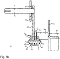
Fig. 3a ; und - Fig. 5b
- eine Detailansicht des Ausschnittes B gemäß der
Fig. 5a . - Eine mögliche Ausführungsform des erfindungsgemäßen Fahrzeugsitzes ist gemäß der Figur 1 abgebildet. Mittels des abgebildeten Koordinatensystems sind die Sitzlängsrichtung 1x, die Sitzbreitenrichtung 1y und die Sitzhöhenrichtung 1z veranschaulicht.
- Vorab sei erwähnt, dass die
Figuren 2a und5a beide Seiten L, R des Fahrzeugsitzes 1 zeigen. DieFiguren 1 ,2b ,3c und4b zeigen die aus Sicht des Sitzinsassen linke Seite L des Fahrzeugsitzes 1. DieFiguren 3a, 3b ,4a und5b zeigen die aus Sicht des Sitzinsassen rechte Seite R des Fahrzeugsitzes 1. Gemäß derFigur 3a ist ferner eine Ebene E1 veranschaulicht, welche die Schnittebene für die Ansicht gemäß derFig. 5a repräsentiert und durch die Achse 7a und die Drehachse 71 verlaufend angeordnet ist. - Der Fahrzeugsitz 1 weist beispielsweise ein Sitzteil 2 und ein Rückenlehnenteil 3 auf. An beiden Seiten L, R des Fahrzeugsitzes 1 ist jeweils eine Bedieneinrichtung 4, 4' zum Bedienen von Fahrzeugsitz- und/ oder Fahrzeugfunktionen, vorliegend in Form eines Joysticks, angeordnet, wobei gemäß
Fig. 1 die Bedieneinrichtung 4 auf der rechten Seite R von der Bedieneinrichtung 4' auf der linken Seite L überdeckt wird. Ebenfalls ist eine Verstelleinrichtung 5 zur Verstellung einer vertikalen Position und/ oder eines Neigungsgrades der Bedieneinrichtungen 4, 4' angeordnet. - Gezeigt ist also gemäß der
Fig. 1 ein Fahrzeugsitz 1 mit einer seitlich, in diesem Fall auf der linken Seite L angeordneten Bedieneinrichtung 4' zum Bedienen von Fahrzeugsitz- und/ oder Fahrzeugfunktionen und einer Verstelleinrichtung 5 zur Verstellung einer vertikalen Position Δz und/ oder eines Neigungsgrades α der Bedieneinrichtungen 4, 4' gegenüber einem Rest des Fahrzeugsitzes 1. - Dabei umfasst die Verstelleinrichtung 5 auf der rechten Seite R eine in Sitzbreitenrichtung 1y verlaufende Drehachse 6 und eine mit der Bedieneinrichtung 4 verbundene Welle 7, welche beabstandet zur Drehachse 6 und zusammen mit der Bedieneinrichtung 4 um die Drehachse 6 verschwenkbar angeordnet ist.
- Auf der linken Seite L ist spiegelsymmetrisch zu einer Ebene E2, welche in Sitzhöhenrichtung 1z und Sitzlängsrichtung 1x verlaufend angeordnet ist (siehe
Fig. 1 ), eine weitere in Sitzbreitenrichtung 1y verlaufende Drehachse 6' der Verstelleinrichtung 5 und eine weitere mit der Bedieneinrichtung 4' verbundene Welle 7' angeordnet, wobei die weitere Welle 7' beabstandet zur Drehachse 6' und zusammen mit der Bedieneinrichtung 4' um die Drehachse 6' verschwenkbar angeordnet ist. - Alle weiteren Beschreibungen, welche sich auf spiegelbildlich angeordnete Elemente beziehen, gelten also analog für beide Seiten L, R des Fahrzeugsitzes 1, auch wenn sie der Übersichtlichkeit wegen nur für eine Seite L oder R beschrieben sind. Dies gilt insbesondere für folgende Elemente, welche auf beide Seiten L und R des Fahrzeugsitzes angeordnet sind: Bedieneinrichtungen 4, 4', Drehachsen 6, 6' mit Mittelachsen 6a, 6a', Wellen 7, 7'mit Mittelachsen 7a, 7a', Kulissenelemente 10, 10' mit Führungskulissen 8, 8', erste Hebelelemente 28, 28' und zweite Hebelelemente 31, 31'. Die Elemente auf der linken Seite L werden dabei mit einem Strich (Beispiel: Drehachse 6') und die Elemente auf der rechten Seite R ohne Strich (Beispiel: Drehachse 6) bezeichnet.
- Ebenfalls zu sehen gemäß der
Fig. 1 ist das Griffelement 92 eines Spindelelements 22 (siehe vor allemFig. 2a und3b ). Die Verstellung der vertikalen Position Δz und/ oder des Neigungsgrades α der Bedieneinrichtungen 4, 4' ist vorliegend mittels einer Drehbewegung des in Wirkkontakt mit der Welle 7 stehenden Spindelelements 22 der Verstelleinrichtung 5 durchführbar, wobei eine Mittelachse 22a des Spindelelements 22 senkrecht zu einer Mittelachse 7a der Welle 7 angeordnet ist. Vorliegend ist das Spindelelement 22 vollständig unterhalb der Welle 7 angeordnet. Die Drehbewegung des Spindelelements 22 ist mittels einer Drehung des Griffelements durchführbar. - Wie nachstehend noch erläutert wird, steht das Spindelelement 22 auch in Wirkkontakt mit der weiteren Welle 7'; ferner ist die Mittelachse 22a des Spindelelements 22 senkrecht zu einer Mittelachse 7a' der Welle 7' angeordnet. Vorliegend ist das Spindelelement 22 vollständig unterhalb der Welle 7' angeordnet.
- Vorliegend weist ein Abstand ΔL zwischen der Mittelachse 6a der Drehachse 6 und der Mittelachse 7a der Welle 7 einen Wert von 237,4 mm auf.
- Die
Fig. 4a zeigt, dass das Spindelelement 22 mit dem als Handknauf ausgestalteten Griffelement 92 verbunden ist und dass das Griffelement 92 mit einer Anzeigeeinrichtung 93 versehen ist, welche als Drehpfeil mit Doppelspitze ausgestaltet ist und mit den Zeichen "+" für "Höher stellen" oder "-" für "Tiefer stellen" versehen ist. - Vorliegend ist dieses Griffelement 92 in Längsrichtung 1x des Fahrzeugsitzes 1 neben dem Spindelelement 22, auf der rechten Seite R des Fahrzeugsitzes 1 und unterhalb des Sitzteils 3 des Fahrzeugsitzes 1 angeordnet.
- Vorliegend ist der Fahrzeugsitz 1 mit einer einzelnen Verstelleinrichtung 5 und an seinen beiden Seiten, also zur linken L und zur rechten Seite R des Benutzers, mit jeweils einer Bedieneinrichtung 4, 4' versehen.
- Vorliegend ist dabei der Abstand ΔL zwischen der Drehachse 6 und der Welle 7 fest eingestellt und die Drehachse 6 in Sitzlängsrichtung 1x hinter der Welle 7 und in Sitzhöhenrichtung 1z oberhalb der Welle 7 angeordnet. Ferner ist die Welle 7 in Sitzhöhenrichtung 1z oberhalb des Spindelelements 22 angeordnet.
- Als Teil der Wirkverbindung zwischen der Welle 7 und dem Spindelelement 22 ist an einem ersten Ende 26a des Spindelelements 22 ein Schlittenelement 23 angeordnet, wobei ein Innengewinde 25 des Schlittenelements 23 mit einem Außengewinde 29 des Spindelelements 22 in Wirkkontakt steht (siehe
Fig. 3b ), so dass die Drehbewegung des Spindelelements 22 in eine Translationsbewegung des Schlittenelements 23 übertragbar ist. Vorliegend ist ein gekanntetes Blechteil als ein Lagerelement 90 angeordnet, mittels welchem das Spindelelement 22 in Relation zu einem Sitzunterbau 40 des Fahrzeugsitzes 1 drehbar gelagert ist, und welches indirekt mit dem Sitzunterbau 40 verbunden ist. Gemäß denFiguren 3a bis 3c ist eine Lagereinheit 91 zu sehen, mittels welcher das Spindelelement 22 mit dem Lagerelement 90 verbunden ist. Diese Lagereinheit 91 umfasst beispielsweise Kugellager, Buchsen und/ oder Scheiben und wird vorliegend nicht näher beschrieben. - Als weiterer Teil der Wirkverbindung zwischen dem Spindelelement 22 und der Welle 7 ist ferner an einem dem Spindelelement 22 abgewandten ersten Ende 27a des Schlittenelements 23 ein erstes Hebelelement 28 mittels eines ersten Endes 28a um eine Drehachse 71 drehbar gelagert, wobei ein zweites Ende 28b des ersten Hebelelements 28 mit der Welle 7 verbunden ist.
- Vorliegend ist das erste Ende 28a des ersten Hebelelements 28 und das erste Ende des Schlittenelements 23 jeweils mit einer Bohrung versehen, mittels welcher jeweils die Aufnahme eines Drehlagerelements zur beschriebenen drehbaren Lagerung beider Elemente 28, 22 um die Drehachse 71 zueinander ermöglicht ist.
- Das Drehlagerelement umfasst gemäß
Fig. 5b ein Wellenelement 80 sowie zwei Gabelelemente 50, 51, welche vorliegend als plattenförmige Elemente ausgestaltet und auf dem Wellenelement 80 zu einer Seite des ersten 28 oder des zweiten Hebelelements 31 angeordnet sind. Vorliegend bildet das erste Ende 27a des Schlittenelements 23 die Gabelelemente 50, 51 aus. - Ferner umfasst das Drehlagerelement Sicherungselemente 60, welche vorliegend als Außensicherungsringe ausgestaltet und zu einer Seite der Gabelelemente 50, 51 angeordnet sind. Zwischen einem Wellenelement 80 und den Gabelelementen 50, 51 sowie den Hebelelementen 28, 31 sind Buchsenelemente 61 in Form von Sinterbundbuchsen angeordnet.
- Da das Schlittenelement 23 nur auf der rechten Seite R des Fahrzeugsitzes 1 angeordnet ist, umfasst die linke Seite L ein im Vergleich zum Wellenelement 80 kürzeres Wellenelement 80', Sicherungselemente 60', jedoch keine Gabelelemente.
- Vorliegend sind das Spindelelement 22, das Schlittenelement 23 und das erste Hebelelement 28 hinsichtlich ihrer Längserstreckung parallel zueinander angeordnet. Analog dazu sind das Schlittenelement 23 und das erste Hebelelement 28 hinsichtlich ihrer Längserstreckung genau wie die Mittelachse 22a des Spindelelements 22 senkrecht zur Mittelachse 7a der Welle 7 angeordnet.
- Vorliegend ist die Welle 7 hinsichtlich der Verschwenkung um die Drehachse 6 innerhalb einer Führungskulisse 8 eines Kulissenelements 10 bewegbar (siehe
Fig. 3a und3c ), wobei eine Form der Führungskulisse 8 entlang eines Abschnittes eines Bogens B verlaufend ausgestaltet ist, wobei der Bogen B vorliegend konzentrisch um die Drehachse 6 verlaufend ausgestaltet ist. Dabei ist das Kulissenelement 10 an einer Lagerstelle des Sitzunterbaus 40 angeordnet und nicht mit der Welle 7 bewegbar. - Der Sitzunterbau 40 umfasst vorliegend zwei sich in Sitzlängsrichtung 1x erstreckende Längsstreben 41, 41' sowie eine vordere 42 und eine hintere Querstrebe 43, welche sich jeweils in Sitzbreitenrichtung 1y erstrecken. Es bildet die hintere Querstrebe 43 die Lagerstelle für die Drehachse 6, 6' auf beiden Seiten des Sitzunterbaus 40 auf. Die hintere Querstrebe 43 ist also von der linken Seite L bis zur rechten Seite R des Fahrzeugsitzes 1 durchgehend ausgebildet. Vorliegend ist sie noch auf beiden Seiten mittels je einer Versteifungsstrebe 44, 44' in Form eines Knotenblechs verstärkt, welche vorliegend mit der hinteren Querstrebe 43 verschweißt ist.
- Vorliegend ist die Drehachse 6 durch eine Bohrung in der hinteren Querstrebe 43 geführt und mit dem Knotenblech 44 mittels einer Schweißverbindung starr verbunden.
- Gemäß
Fig. 2a und3b ist zu sehen, dass das Lagerelement 90 für das Spindelelement 22 unmittelbar und vollständig unterhalb des Kulissenelements 10 angeordnet und mit diesem verbunden ist. - Weiter ist gemäß
Fig. 1 gezeigt, dass die Bedieneinrichtung 4 und die Welle 7 mittels eines Zwischenelements 94 verbunden sind, wobei dieses Zwischenelement 94 vorliegend als Gehäuseteil ausgebildet ist. Innerhalb oder an diesem Zwischenelement 94 sind nicht gezeigte weitere Elemente wie die Elektronikkomponenten, die Stromversorgung oder die Steuerung der Bedieneinrichtung angeordnet. - Innerhalb der oben beschriebenen Führungskulisse 8 kann somit die Welle 7 um einen bestimmten Winkel, bevorzugt um +4° bis -4° ausgehend von einer Grundstellung von 0°, mechanisch sicher geführt verschwenkt werden. Es ist verständlich, dass mit der Welle 7 sich die gesamte Bedieneinrichtung 4 mit verschwenkt, und zwar um die Drehachse 6.
- Der gezeigte Fahrzeugsitz 1 weist wie erwähnt zwei Bedieneinrichtungen 4, 4' auf, wovon eine 4' links L und die andere 4 rechts R der Sitzfläche angeordnet ist. Die Verstelleinrichtung 5 ist auf beiden Seiten L, R des Fahrzeugsitzes 1 angeordnet, wobei jedoch nur ein Teil der Komponenten oder Elemente der Verstelleinrichtung 5 in zweifacher Ausführung und auf beiden Seiten L, R angeordnet sind.
- Demnach sind das Spindelelement 22, das Schlittenelement 23, das Griffelement 92 mit Anzeigeeinrichtung 93, das Lagerelement 90 sowie nicht näher bezeichnete Mittel zur Verbindung dieser Elemente 22, 23, 92, 93, 90 oder zur Anbindung dieser Elemente 22, 23, 92, 93, 90 an den Rest des Fahrzeugsitzes 1 nur auf einer Seite, vorliegend nur auf der rechten Seite R des Fahrzeugsitzes 1 angeordnet.
- Auf beiden Seiten L, R des Fahrzeugsitzes 1 angeordnet und somit in zweifacher Ausführung vorhanden sind vorliegend die Drehachse 6, 6', die Welle 7, 7', das Kulissenelement 10, 10', das erste Hebelelement 28, 28' und das zweite Hebelelement 31, 31' sowie nicht näher bezeichnete Mittel zur Verbindung dieser Elemente oder zur Anbindung dieser Elemente 6, 6', 7, 7', 10, 10', 28, 28', 31, 31' an den Rest des Fahrzeugsitzes 1.
- Dabei sind die Elemente 6, 7, 10, 28, 31 der Verstelleinrichtung 5, welche auf der ersten oder rechten Seite R des Fahrzeugsitzes 1 angeordnet sind, identisch ausgestaltet zu den ihnen entsprechenden Elementen 6', 7', 10', 28', 31', welche auf der zweiten oder linken Seite L des Fahrzeugsitzes 1 angeordnet sind.
- In Sitzbreitenrichtung 1y ist ein Wellenelement 30 angeordnet ist, dessen erstes Ende 30a mittels des mit dem Wellenelement 30 starr verbundenen zweiten Hebelelements 31 mit dem ersten Ende 28a des ersten Hebelelements 28 drehbar verbunden ist, wobei ein zweites Ende 30b des Wellenelements 30 mit dem weiteren zweiten Hebelelement 31' starr verbunden ist.
- Das weitere zweite Hebelelement 31' ist ebenfalls drehbar mit einem ersten Ende 28a' eines weiteren ersten Hebelelements 28' verbunden (siehe insbesondere
Fig. 5a ). Dieses erste Ende 28a' des Weiteren ersten Hebelelements 28' ist wiederum mittels eines zweiten Endes 28b' mit einer weiteren Welle 7' verbunden. Diese weitere Welle 7' ist wiederum mit der weiteren Bedieneinrichtung 4' verbunden. - Vorliegend ist das Wellenelement 30 drehbar am Sitzunterbau 40 gelagert. Dafür weisen beide Längsstreben 41, 41' jeweils eine Bohrung auf, durch die das Wellenelement 30 hindurchgeführt angeordnet ist. Buchsenelemente 95, 95' sind zwischen den Längsstreben 41, 41' und den zweiten Hebelelementen 31, 31' an beiden Enden 30a, 30b des Wellenelements 30 angeordnet und sorgen für eine axiale Sicherung des Wellenelements 30, also in Sitzbreitenrichtung 1y.
- Das erste Hebelelement 28 ist mit dem einen Ende 27a des Schlittenelements 23 verbunden und mittels der Drehachse 71 drehbar zu diesem gelagert. Ebenfalls ist das zweite Hebelelement 31 mit dem einen Ende 27a des Schlittenelements 23 verbunden und mittels der Drehachse 71 drehbar zu diesem gelagert.
- Da über die zentral angeordnete Welle 30 und mittels der beschriebenen Mechanik die Drehbewegung des Spindelelements 22 in eine Drehbewegung der Welle 7' auf der linken Seite L und gleichzeitig in eine Drehbewegung der Welle 7 auf der rechten Seite R des Fahrzeugsitzes 1 übertragbar ist, ist also mittels eines einzigen Spindelelements 23 eine Verstellung der vertikalen Position Δz und/ oder des Neigungsgrades α von beiden Bedieneinrichtungen 4, 4' durchführbar.
- Es versteht sich, dass es sich bei dem vorstehend erläuterten Ausführungsbeispiel lediglich um eine erste Ausgestaltung des erfindungsgemäßen Fahrzeugsitzes handelt. Insofern beschränkt sich die Ausgestaltung der Erfindung nicht auf dieses Ausführungsbeispiel.
- Sämtliche in den Anmeldungsunterlagen offenbarten Merkmale werden als erfindungswesentlich beansprucht, sofern sie einzeln oder in Kombination gegenüber dem Stand der Technik neu sind.
-
- 1
- Fahrzeugsitz
- 1x
- Sitzlängsrichtung
- 1y
- Sitzbreitenrichtung
- 1z
- Sitzhöhenrichtung
- 4, 4'
- Bedieneinrichtung
- 5
- Verstelleinrichtung
- 6, 6'
- Drehachse
- 6a, 7a, 22a
- Mittelachse
- 7, 7'
- Welle
- 8, 8'
- Führungskulisse
- 10, 10'
- Kulissenelement
- 22
- Spindelelement
- 23
- Schlittenelement
- 25
- Innengewinde
- 26a, 27a, 28a, 28a', 28b, 28b', 30a, 30b
- Ende
- 28, 28', 31, 31'
- Hebelelement
- 29
- Außengewinde
- 30, 80, 80'
- Wellenelement
- 40
- Sitzunterbau
- 41, 41'
- Längsstrebe
- 42, 43
- Querstrebe
- 44
- Versteifungsstrebe
- 50, 51
- Gabelelement
- 60
- Sicherungselement
- 61, 95, 95'
- Buchsenelement
- 70, 71
- Achse
- 90
- Lagerelement
- 91
- Lagereinheit
- 92
- Griffelement
- 93
- Anzeigeeinrichtung
- 94
- Zwischenelement
- B
- Bogen
- E1, E2
- Ebene
- L, R
- Seite
- α
- Neigungsgrad
- ΔL
- Abstand
- Δz
- vertikale Position
Claims (7)
- Fahrzeugsitz (1) mit mindestens einer seitlich angeordneten Bedieneinrichtung (4, 4') zum Bedienen von Fahrzeugsitz- und/ oder Fahrzeugfunktionen und einer Verstelleinrichtung (5) zur Verstellung einer vertikalen Position (Δz) und/ oder eines Neigungsgrades (α) der mindestens einen Bedieneinrichtung (4, 4') gegenüber einem Rest des Fahrzeugsitzes (1),
wobei die Verstelleinrichtung (5) eine in Sitzbreitenrichtung (1y) verlaufende Drehachse (6, 6') und eine mit der Bedieneinrichtung (4, 4') verbundene Welle (7, 7'), welche beabstandet zur Drehachse (6, 6') und zusammen mit der Bedieneinrichtung (4, 4') um die Drehachse (6, 6') verschwenkbar angeordnet ist, umfasst, dadurch gekennzeichnet, dass
die Verstellung der vertikalen Position (Δz) und/ oder des Neigungsgrades (α) der Bedieneinrichtung (4, 4') mittels einer Drehbewegung eines in Wirkkontakt mit der Welle (7, 7') stehenden Spindelelements (22) der Verstelleinrichtung (5) durchführbar ist, wobei eine Mittelachse (22a) des Spindelelements (22) senkrecht zu einer Mittelachse (7a, 7a') der Welle (7, 7') angeordnet ist. - Fahrzeugsitz (1) nach Anspruch 1,
dadurch gekennzeichnet, dass
ein Abstand (ΔL) zwischen der Drehachse (6, 6') und der Welle (7, 7') fest einstellbar und die Drehachse (6, 6') in Sitzlängsrichtung (1x) hinter der Welle (7, 7') angeordnet ist. - Fahrzeugsitz (1) nach Anspruch 1 oder 2,
dadurch gekennzeichnet, dass
an einem ersten Ende (26a) des Spindelelements (22) ein Schlittenelement (23) angeordnet ist, wobei ein Innengewinde (25) des Schlittenelements (23) mit einem Außengewinde (29) des Spindelelements (22) in Wirkkontakt steht, so dass die Drehbewegung des Spindelelements (22) in eine Translationsbewegung des Schlittenelements (23) übertragbar ist. - Fahrzeugsitz (1) nach einem der vorhergehenden Ansprüche,
dadurch gekennzeichnet, dass
mittels der Wechselwirkung zwischen dem Innengewinde (25) des Schlittenelements (23) und dem Außengewinde (29) des Spindelelements (22) eine Arretierung der Welle (7, 7') erreichbar ist, wobei die Verstelleinrichtung (5) frei von einer zusätzlichen Arretiereinrichtung zum Arretieren einer Position der Welle (7, 7') in Bezug auf die Verschwenkung um die Drehachse (6, 6') ausgestaltet ist. - Fahrzeugsitz (1) nach einem der vorhergehenden Ansprüche,
dadurch gekennzeichnet, dass
an einem dem Spindelelement (22) abgewandten ersten Ende (27a) des Schlittenelements (23) ein erstes Hebelelement (28) mittels eines ersten Endes (28a) drehbar gelagert ist, wobei ein zweites Ende (28b) des erstes Hebelelements (28) mit der Welle (7) verbunden ist. - Fahrzeugsitz (1) nach einem der vorhergehenden Ansprüche,
dadurch gekennzeichnet, dass
die Welle (7, 7') hinsichtlich der Verschwenkung um die Drehachse (6, 6') innerhalb einer Führungskulisse (8, 8') eines Kulissenelements (10, 10') bewegbar ist, wobei eine Form der Führungskulisse (8, 8') entlang eines Abschnittes eines Bogens (B) verlaufend ausgestaltet ist, wobei der Bogen (B) bevorzugt konzentrisch um die Drehachse (6, 6') verlaufend ausgestaltet ist. - Fahrzeugsitz (1) nach einem der vorhergehenden Ansprüche,
dadurch gekennzeichnet, dass
in Sitzbreitenrichtung (1y) ein Wellenelement (30) angeordnet ist, dessen erstes Ende (30a) mittels eines mit dem Wellenelement (30) starr verbundenen zweiten Hebelelements (31) mit dem ersten Ende (28a) des ersten Hebelelements (28) drehbar verbunden ist, wobei ein zweites Ende (30b) des Wellenelements (30) mit einem weiteren zweiten Hebelelement (31') starr verbunden ist.
Applications Claiming Priority (1)
| Application Number | Priority Date | Filing Date | Title |
|---|---|---|---|
| DE102017129556.9A DE102017129556B4 (de) | 2017-12-12 | 2017-12-12 | Fahrzeugsitz mit Verstelleinrichtung |
Publications (2)
| Publication Number | Publication Date |
|---|---|
| EP3498526A1 true EP3498526A1 (de) | 2019-06-19 |
| EP3498526B1 EP3498526B1 (de) | 2020-04-22 |
Family
ID=64308580
Family Applications (1)
| Application Number | Title | Priority Date | Filing Date |
|---|---|---|---|
| EP18205847.9A Active EP3498526B1 (de) | 2017-12-12 | 2018-11-13 | Fahrzeugsitz mit verstelleinrichtung |
Country Status (4)
| Country | Link |
|---|---|
| US (1) | US10859147B2 (de) |
| EP (1) | EP3498526B1 (de) |
| CN (1) | CN109910693B (de) |
| DE (1) | DE102017129556B4 (de) |
Families Citing this family (2)
| Publication number | Priority date | Publication date | Assignee | Title |
|---|---|---|---|---|
| DE102017126429B4 (de) * | 2017-11-10 | 2021-03-18 | Grammer Aktiengesellschaft | Fahrzeugsitz mit einer Bedieneinrichtung und einer Verstelleinrichtung |
| DE102024132002A1 (de) * | 2024-11-04 | 2026-05-07 | Grammer Aktiengesellschaft | Fahrzeugsitz mit verstellbarer Konsole |
Citations (1)
| Publication number | Priority date | Publication date | Assignee | Title |
|---|---|---|---|---|
| EP1982865A2 (de) * | 2007-04-16 | 2008-10-22 | Volvo Construction Equipment Holding Sweden AB | Vorrichtung zur Höhenverstellung für Baumaschinen-Konsolenkisten mit Gewichtsausgleich |
Family Cites Families (12)
| Publication number | Priority date | Publication date | Assignee | Title |
|---|---|---|---|---|
| JPS5835U (ja) * | 1981-06-26 | 1983-01-05 | トヨタ自動車株式会社 | 座席前部の高さ調節装置 |
| NL8200614A (nl) * | 1982-02-17 | 1983-09-16 | Rotterdamsche Droogdok Mij | Bedrijfsvoertuig. |
| US4995580A (en) * | 1989-07-31 | 1991-02-26 | Tachi-S. Co., Ltd. | Height adjusting device for vehicle seat |
| RU2012740C1 (ru) * | 1992-06-15 | 1994-05-15 | Бородянский экскаваторный завод | Механизм установки и регулировки сидения землеройно-транспортной машины |
| US6341821B1 (en) * | 2000-02-04 | 2002-01-29 | Vincent Rousseau | Ergonomic armrest and joystick assembly |
| KR100430399B1 (ko) * | 2001-12-18 | 2004-05-04 | 볼보 컨스트럭션 이키프먼트 홀딩 스웨덴 에이비 | 중장비 조종박스의 높낮이 조절장치 |
| JP4085675B2 (ja) * | 2002-04-01 | 2008-05-14 | 株式会社豊田自動織機 | 産業車両 |
| KR100900434B1 (ko) * | 2007-04-16 | 2009-06-01 | 볼보 컨스트럭션 이키프먼트 홀딩 스웨덴 에이비 | 전후방향의 완충수단이 장착된 중장비용 시이트 |
| JP4486662B2 (ja) * | 2007-06-15 | 2010-06-23 | キャタピラージャパン株式会社 | 建設機械のコンソール高さ調整装置 |
| US8585004B1 (en) * | 2009-01-26 | 2013-11-19 | Atwood Mobile Products Llc | Air ride seat pedestal with independent height adjustment |
| DE102009053537B4 (de) * | 2009-11-18 | 2014-05-15 | F.S. Fehrer Automotive Gmbh | Schwenkbare Armlehne zur Verwendung in einem Fahrzeug |
| CN202345451U (zh) * | 2011-11-05 | 2012-07-25 | 钟声远 | 一种机械式减振装置 |
-
2017
- 2017-12-12 DE DE102017129556.9A patent/DE102017129556B4/de active Active
-
2018
- 2018-11-13 EP EP18205847.9A patent/EP3498526B1/de active Active
- 2018-12-12 US US16/217,205 patent/US10859147B2/en active Active
- 2018-12-12 CN CN201811518246.2A patent/CN109910693B/zh active Active
Patent Citations (1)
| Publication number | Priority date | Publication date | Assignee | Title |
|---|---|---|---|---|
| EP1982865A2 (de) * | 2007-04-16 | 2008-10-22 | Volvo Construction Equipment Holding Sweden AB | Vorrichtung zur Höhenverstellung für Baumaschinen-Konsolenkisten mit Gewichtsausgleich |
Also Published As
| Publication number | Publication date |
|---|---|
| DE102017129556B4 (de) | 2023-03-09 |
| US20190178355A1 (en) | 2019-06-13 |
| DE102017129556A1 (de) | 2019-06-13 |
| EP3498526B1 (de) | 2020-04-22 |
| CN109910693B (zh) | 2021-08-24 |
| US10859147B2 (en) | 2020-12-08 |
| CN109910693A (zh) | 2019-06-21 |
Similar Documents
| Publication | Publication Date | Title |
|---|---|---|
| DE102014107816B4 (de) | Nutzfahrzeugsitz mit arretierbarem Querschlittenteil | |
| EP2374657B1 (de) | Armlehne und Bedienarbeitsplatz mit einer solchen Armlehne | |
| DE102017126429B4 (de) | Fahrzeugsitz mit einer Bedieneinrichtung und einer Verstelleinrichtung | |
| EP3552874B1 (de) | Fahrzeugsitz mit verstellbarer schaltkonsole | |
| EP2962674B1 (de) | Vorrichtung zur höhenverstellung eines operationstischs | |
| EP3500137B1 (de) | Sitzmöbelstück | |
| DE69301435T2 (de) | Fahrzeugsitz mit mehrfachen Einstellungen | |
| DE10239722B4 (de) | Höheneinstellvorrichtung für Schaltkästen an Fahrzeug-Fahrersitzen | |
| EP1360085B1 (de) | Sitz, insbesondere Fahrzeugsitz, vorzugsweise Fluggastsitz | |
| EP3263398B1 (de) | Federungsvorrichtung | |
| DE4301811B4 (de) | Rückenlehnengelenk für einen Fahrzeugsitz mit einem Sitzträger und einer an diesem angelenkten Rückenlehne | |
| EP3263397B1 (de) | Federungsvorrichtung | |
| WO2005080127A1 (de) | Fahrzeugsitz, insbesondere für ein kraftfahrzeug, mit einer klappbaren lehne und einer klappbaren sitzbasis und verfahren | |
| DE102024002956A1 (de) | Displayanordnung für einen Kraftwagen sowie Kraftwagen mit einer Displayanordnung | |
| EP3604889A1 (de) | Vorrichtung mit schwenkbarer befestigungsplatte für ein anzeigegerät | |
| EP3498526B1 (de) | Fahrzeugsitz mit verstelleinrichtung | |
| EP0602361B1 (de) | Rückenlehnengelenk für einen Fahrzeugsitz | |
| EP1850699B1 (de) | Möbel, insbesondere sitzmöbel | |
| DE102014107814B4 (de) | Nutzfahrzeugsitz | |
| EP3815963B1 (de) | Vorrichtung zur einstellung einer sitzposition | |
| DE102018108795B4 (de) | Fahrzeugsitz mit verstellbarer Schaltkonsole | |
| DE10318718A1 (de) | Verstellbarer Kraftfahrzeugsitz, insbesondere für die zweite und dritte Sitzreihe | |
| DE4302329A1 (de) | Höhenverstelleinrichtung für Sitze, insbesondere Kraftfahrzeugsitze | |
| DE102018213141B3 (de) | Verstellvorrichtung für eine zumindest abschnittsweise Absenkung eines Sitzteils mit Antriebseinrichtung | |
| DE102012112524B4 (de) | Nutzfahrzeugsitz |
Legal Events
| Date | Code | Title | Description |
|---|---|---|---|
| PUAI | Public reference made under article 153(3) epc to a published international application that has entered the european phase |
Free format text: ORIGINAL CODE: 0009012 |
|
| STAA | Information on the status of an ep patent application or granted ep patent |
Free format text: STATUS: THE APPLICATION HAS BEEN PUBLISHED |
|
| AK | Designated contracting states |
Kind code of ref document: A1 Designated state(s): AL AT BE BG CH CY CZ DE DK EE ES FI FR GB GR HR HU IE IS IT LI LT LU LV MC MK MT NL NO PL PT RO RS SE SI SK SM TR |
|
| AX | Request for extension of the european patent |
Extension state: BA ME |
|
| STAA | Information on the status of an ep patent application or granted ep patent |
Free format text: STATUS: REQUEST FOR EXAMINATION WAS MADE |
|
| 17P | Request for examination filed |
Effective date: 20191016 |
|
| RBV | Designated contracting states (corrected) |
Designated state(s): AL AT BE BG CH CY CZ DE DK EE ES FI FR GB GR HR HU IE IS IT LI LT LU LV MC MK MT NL NO PL PT RO RS SE SI SK SM TR |
|
| GRAP | Despatch of communication of intention to grant a patent |
Free format text: ORIGINAL CODE: EPIDOSNIGR1 |
|
| STAA | Information on the status of an ep patent application or granted ep patent |
Free format text: STATUS: GRANT OF PATENT IS INTENDED |
|
| INTG | Intention to grant announced |
Effective date: 20200117 |
|
| GRAS | Grant fee paid |
Free format text: ORIGINAL CODE: EPIDOSNIGR3 |
|
| GRAA | (expected) grant |
Free format text: ORIGINAL CODE: 0009210 |
|
| STAA | Information on the status of an ep patent application or granted ep patent |
Free format text: STATUS: THE PATENT HAS BEEN GRANTED |
|
| AK | Designated contracting states |
Kind code of ref document: B1 Designated state(s): AL AT BE BG CH CY CZ DE DK EE ES FI FR GB GR HR HU IE IS IT LI LT LU LV MC MK MT NL NO PL PT RO RS SE SI SK SM TR |
|
| REG | Reference to a national code |
Ref country code: CH Ref legal event code: EP |
|
| REG | Reference to a national code |
Ref country code: IE Ref legal event code: FG4D Free format text: LANGUAGE OF EP DOCUMENT: GERMAN |
|
| REG | Reference to a national code |
Ref country code: DE Ref legal event code: R096 Ref document number: 502018001269 Country of ref document: DE |
|
| REG | Reference to a national code |
Ref country code: AT Ref legal event code: REF Ref document number: 1259654 Country of ref document: AT Kind code of ref document: T Effective date: 20200515 |
|
| REG | Reference to a national code |
Ref country code: LT Ref legal event code: MG4D |
|
| REG | Reference to a national code |
Ref country code: NL Ref legal event code: MP Effective date: 20200422 |
|
| RAP2 | Party data changed (patent owner data changed or rights of a patent transferred) |
Owner name: GRAMMER AG |
|
| PG25 | Lapsed in a contracting state [announced via postgrant information from national office to epo] |
Ref country code: GR Free format text: LAPSE BECAUSE OF FAILURE TO SUBMIT A TRANSLATION OF THE DESCRIPTION OR TO PAY THE FEE WITHIN THE PRESCRIBED TIME-LIMIT Effective date: 20200723 Ref country code: FI Free format text: LAPSE BECAUSE OF FAILURE TO SUBMIT A TRANSLATION OF THE DESCRIPTION OR TO PAY THE FEE WITHIN THE PRESCRIBED TIME-LIMIT Effective date: 20200422 Ref country code: PT Free format text: LAPSE BECAUSE OF FAILURE TO SUBMIT A TRANSLATION OF THE DESCRIPTION OR TO PAY THE FEE WITHIN THE PRESCRIBED TIME-LIMIT Effective date: 20200824 Ref country code: NO Free format text: LAPSE BECAUSE OF FAILURE TO SUBMIT A TRANSLATION OF THE DESCRIPTION OR TO PAY THE FEE WITHIN THE PRESCRIBED TIME-LIMIT Effective date: 20200722 Ref country code: IS Free format text: LAPSE BECAUSE OF FAILURE TO SUBMIT A TRANSLATION OF THE DESCRIPTION OR TO PAY THE FEE WITHIN THE PRESCRIBED TIME-LIMIT Effective date: 20200822 Ref country code: SE Free format text: LAPSE BECAUSE OF FAILURE TO SUBMIT A TRANSLATION OF THE DESCRIPTION OR TO PAY THE FEE WITHIN THE PRESCRIBED TIME-LIMIT Effective date: 20200422 Ref country code: NL Free format text: LAPSE BECAUSE OF FAILURE TO SUBMIT A TRANSLATION OF THE DESCRIPTION OR TO PAY THE FEE WITHIN THE PRESCRIBED TIME-LIMIT Effective date: 20200422 Ref country code: LT Free format text: LAPSE BECAUSE OF FAILURE TO SUBMIT A TRANSLATION OF THE DESCRIPTION OR TO PAY THE FEE WITHIN THE PRESCRIBED TIME-LIMIT Effective date: 20200422 |
|
| PG25 | Lapsed in a contracting state [announced via postgrant information from national office to epo] |
Ref country code: HR Free format text: LAPSE BECAUSE OF FAILURE TO SUBMIT A TRANSLATION OF THE DESCRIPTION OR TO PAY THE FEE WITHIN THE PRESCRIBED TIME-LIMIT Effective date: 20200422 Ref country code: LV Free format text: LAPSE BECAUSE OF FAILURE TO SUBMIT A TRANSLATION OF THE DESCRIPTION OR TO PAY THE FEE WITHIN THE PRESCRIBED TIME-LIMIT Effective date: 20200422 Ref country code: RS Free format text: LAPSE BECAUSE OF FAILURE TO SUBMIT A TRANSLATION OF THE DESCRIPTION OR TO PAY THE FEE WITHIN THE PRESCRIBED TIME-LIMIT Effective date: 20200422 Ref country code: BG Free format text: LAPSE BECAUSE OF FAILURE TO SUBMIT A TRANSLATION OF THE DESCRIPTION OR TO PAY THE FEE WITHIN THE PRESCRIBED TIME-LIMIT Effective date: 20200722 |
|
| PG25 | Lapsed in a contracting state [announced via postgrant information from national office to epo] |
Ref country code: AL Free format text: LAPSE BECAUSE OF FAILURE TO SUBMIT A TRANSLATION OF THE DESCRIPTION OR TO PAY THE FEE WITHIN THE PRESCRIBED TIME-LIMIT Effective date: 20200422 |
|
| REG | Reference to a national code |
Ref country code: DE Ref legal event code: R097 Ref document number: 502018001269 Country of ref document: DE |
|
| PG25 | Lapsed in a contracting state [announced via postgrant information from national office to epo] |
Ref country code: ES Free format text: LAPSE BECAUSE OF FAILURE TO SUBMIT A TRANSLATION OF THE DESCRIPTION OR TO PAY THE FEE WITHIN THE PRESCRIBED TIME-LIMIT Effective date: 20200422 Ref country code: DK Free format text: LAPSE BECAUSE OF FAILURE TO SUBMIT A TRANSLATION OF THE DESCRIPTION OR TO PAY THE FEE WITHIN THE PRESCRIBED TIME-LIMIT Effective date: 20200422 Ref country code: EE Free format text: LAPSE BECAUSE OF FAILURE TO SUBMIT A TRANSLATION OF THE DESCRIPTION OR TO PAY THE FEE WITHIN THE PRESCRIBED TIME-LIMIT Effective date: 20200422 Ref country code: SM Free format text: LAPSE BECAUSE OF FAILURE TO SUBMIT A TRANSLATION OF THE DESCRIPTION OR TO PAY THE FEE WITHIN THE PRESCRIBED TIME-LIMIT Effective date: 20200422 Ref country code: RO Free format text: LAPSE BECAUSE OF FAILURE TO SUBMIT A TRANSLATION OF THE DESCRIPTION OR TO PAY THE FEE WITHIN THE PRESCRIBED TIME-LIMIT Effective date: 20200422 Ref country code: CZ Free format text: LAPSE BECAUSE OF FAILURE TO SUBMIT A TRANSLATION OF THE DESCRIPTION OR TO PAY THE FEE WITHIN THE PRESCRIBED TIME-LIMIT Effective date: 20200422 |
|
| PG25 | Lapsed in a contracting state [announced via postgrant information from national office to epo] |
Ref country code: SK Free format text: LAPSE BECAUSE OF FAILURE TO SUBMIT A TRANSLATION OF THE DESCRIPTION OR TO PAY THE FEE WITHIN THE PRESCRIBED TIME-LIMIT Effective date: 20200422 Ref country code: PL Free format text: LAPSE BECAUSE OF FAILURE TO SUBMIT A TRANSLATION OF THE DESCRIPTION OR TO PAY THE FEE WITHIN THE PRESCRIBED TIME-LIMIT Effective date: 20200422 |
|
| PLBE | No opposition filed within time limit |
Free format text: ORIGINAL CODE: 0009261 |
|
| STAA | Information on the status of an ep patent application or granted ep patent |
Free format text: STATUS: NO OPPOSITION FILED WITHIN TIME LIMIT |
|
| 26N | No opposition filed |
Effective date: 20210125 |
|
| PG25 | Lapsed in a contracting state [announced via postgrant information from national office to epo] |
Ref country code: SI Free format text: LAPSE BECAUSE OF FAILURE TO SUBMIT A TRANSLATION OF THE DESCRIPTION OR TO PAY THE FEE WITHIN THE PRESCRIBED TIME-LIMIT Effective date: 20200422 |
|
| PG25 | Lapsed in a contracting state [announced via postgrant information from national office to epo] |
Ref country code: MC Free format text: LAPSE BECAUSE OF FAILURE TO SUBMIT A TRANSLATION OF THE DESCRIPTION OR TO PAY THE FEE WITHIN THE PRESCRIBED TIME-LIMIT Effective date: 20200422 |
|
| PG25 | Lapsed in a contracting state [announced via postgrant information from national office to epo] |
Ref country code: LU Free format text: LAPSE BECAUSE OF NON-PAYMENT OF DUE FEES Effective date: 20201113 |
|
| REG | Reference to a national code |
Ref country code: BE Ref legal event code: MM Effective date: 20201130 |
|
| PG25 | Lapsed in a contracting state [announced via postgrant information from national office to epo] |
Ref country code: IE Free format text: LAPSE BECAUSE OF NON-PAYMENT OF DUE FEES Effective date: 20201113 |
|
| PG25 | Lapsed in a contracting state [announced via postgrant information from national office to epo] |
Ref country code: TR Free format text: LAPSE BECAUSE OF FAILURE TO SUBMIT A TRANSLATION OF THE DESCRIPTION OR TO PAY THE FEE WITHIN THE PRESCRIBED TIME-LIMIT Effective date: 20200422 Ref country code: MT Free format text: LAPSE BECAUSE OF FAILURE TO SUBMIT A TRANSLATION OF THE DESCRIPTION OR TO PAY THE FEE WITHIN THE PRESCRIBED TIME-LIMIT Effective date: 20200422 Ref country code: CY Free format text: LAPSE BECAUSE OF FAILURE TO SUBMIT A TRANSLATION OF THE DESCRIPTION OR TO PAY THE FEE WITHIN THE PRESCRIBED TIME-LIMIT Effective date: 20200422 |
|
| PG25 | Lapsed in a contracting state [announced via postgrant information from national office to epo] |
Ref country code: MK Free format text: LAPSE BECAUSE OF FAILURE TO SUBMIT A TRANSLATION OF THE DESCRIPTION OR TO PAY THE FEE WITHIN THE PRESCRIBED TIME-LIMIT Effective date: 20200422 |
|
| REG | Reference to a national code |
Ref country code: CH Ref legal event code: PL |
|
| PG25 | Lapsed in a contracting state [announced via postgrant information from national office to epo] |
Ref country code: BE Free format text: LAPSE BECAUSE OF NON-PAYMENT OF DUE FEES Effective date: 20201130 |
|
| P01 | Opt-out of the competence of the unified patent court (upc) registered |
Effective date: 20230522 |
|
| GBPC | Gb: european patent ceased through non-payment of renewal fee |
Effective date: 20221113 |
|
| PG25 | Lapsed in a contracting state [announced via postgrant information from national office to epo] |
Ref country code: LI Free format text: LAPSE BECAUSE OF NON-PAYMENT OF DUE FEES Effective date: 20220630 Ref country code: CH Free format text: LAPSE BECAUSE OF NON-PAYMENT OF DUE FEES Effective date: 20220630 |
|
| PG25 | Lapsed in a contracting state [announced via postgrant information from national office to epo] |
Ref country code: GB Free format text: LAPSE BECAUSE OF NON-PAYMENT OF DUE FEES Effective date: 20221113 |
|
| REG | Reference to a national code |
Ref country code: AT Ref legal event code: MM01 Ref document number: 1259654 Country of ref document: AT Kind code of ref document: T Effective date: 20231113 |
|
| PG25 | Lapsed in a contracting state [announced via postgrant information from national office to epo] |
Ref country code: AT Free format text: LAPSE BECAUSE OF NON-PAYMENT OF DUE FEES Effective date: 20231113 |
|
| PG25 | Lapsed in a contracting state [announced via postgrant information from national office to epo] |
Ref country code: AT Free format text: LAPSE BECAUSE OF NON-PAYMENT OF DUE FEES Effective date: 20231113 |
|
| PGFP | Annual fee paid to national office [announced via postgrant information from national office to epo] |
Ref country code: DE Payment date: 20251118 Year of fee payment: 8 |
|
| PGFP | Annual fee paid to national office [announced via postgrant information from national office to epo] |
Ref country code: IT Payment date: 20251128 Year of fee payment: 8 |
|
| PGFP | Annual fee paid to national office [announced via postgrant information from national office to epo] |
Ref country code: FR Payment date: 20251120 Year of fee payment: 8 |
|
| PGFP | Annual fee paid to national office [announced via postgrant information from national office to epo] |
Ref country code: AT Payment date: 20260410 Year of fee payment: 5 |