EP3498509A1 - Slider-equipped window glass and process for its production - Google Patents
Slider-equipped window glass and process for its production Download PDFInfo
- Publication number
- EP3498509A1 EP3498509A1 EP18210022.2A EP18210022A EP3498509A1 EP 3498509 A1 EP3498509 A1 EP 3498509A1 EP 18210022 A EP18210022 A EP 18210022A EP 3498509 A1 EP3498509 A1 EP 3498509A1
- Authority
- EP
- European Patent Office
- Prior art keywords
- slider
- window glass
- layer portion
- vehicle
- inner layer
- Prior art date
- Legal status (The legal status is an assumption and is not a legal conclusion. Google has not performed a legal analysis and makes no representation as to the accuracy of the status listed.)
- Granted
Links
Images



Classifications
-
- B—PERFORMING OPERATIONS; TRANSPORTING
- B60—VEHICLES IN GENERAL
- B60J—WINDOWS, WINDSCREENS, NON-FIXED ROOFS, DOORS, OR SIMILAR DEVICES FOR VEHICLES; REMOVABLE EXTERNAL PROTECTIVE COVERINGS SPECIALLY ADAPTED FOR VEHICLES
- B60J1/00—Windows; Windscreens; Accessories therefor
- B60J1/08—Windows; Windscreens; Accessories therefor arranged at vehicle sides
- B60J1/12—Windows; Windscreens; Accessories therefor arranged at vehicle sides adjustable
- B60J1/16—Windows; Windscreens; Accessories therefor arranged at vehicle sides adjustable slidable
- B60J1/17—Windows; Windscreens; Accessories therefor arranged at vehicle sides adjustable slidable vertically
-
- B—PERFORMING OPERATIONS; TRANSPORTING
- B60—VEHICLES IN GENERAL
- B60J—WINDOWS, WINDSCREENS, NON-FIXED ROOFS, DOORS, OR SIMILAR DEVICES FOR VEHICLES; REMOVABLE EXTERNAL PROTECTIVE COVERINGS SPECIALLY ADAPTED FOR VEHICLES
- B60J5/00—Doors
- B60J5/04—Doors arranged at the vehicle sides
- B60J5/0401—Upper door structure
- B60J5/0402—Upper door structure window frame details, including sash guides and glass runs
-
- E—FIXED CONSTRUCTIONS
- E05—LOCKS; KEYS; WINDOW OR DOOR FITTINGS; SAFES
- E05D—HINGES OR SUSPENSION DEVICES FOR DOORS, WINDOWS OR WINGS
- E05D15/00—Suspension arrangements for wings
- E05D15/16—Suspension arrangements for wings for wings sliding vertically more or less in their own plane
- E05D15/165—Details, e.g. sliding or rolling guides
-
- B—PERFORMING OPERATIONS; TRANSPORTING
- B60—VEHICLES IN GENERAL
- B60J—WINDOWS, WINDSCREENS, NON-FIXED ROOFS, DOORS, OR SIMILAR DEVICES FOR VEHICLES; REMOVABLE EXTERNAL PROTECTIVE COVERINGS SPECIALLY ADAPTED FOR VEHICLES
- B60J1/00—Windows; Windscreens; Accessories therefor
- B60J1/001—Double glazing for vehicles
-
- B—PERFORMING OPERATIONS; TRANSPORTING
- B60—VEHICLES IN GENERAL
- B60J—WINDOWS, WINDSCREENS, NON-FIXED ROOFS, DOORS, OR SIMILAR DEVICES FOR VEHICLES; REMOVABLE EXTERNAL PROTECTIVE COVERINGS SPECIALLY ADAPTED FOR VEHICLES
- B60J1/00—Windows; Windscreens; Accessories therefor
- B60J1/004—Mounting of windows
-
- E—FIXED CONSTRUCTIONS
- E05—LOCKS; KEYS; WINDOW OR DOOR FITTINGS; SAFES
- E05Y—INDEXING SCHEME ASSOCIATED WITH SUBCLASSES E05D AND E05F, RELATING TO CONSTRUCTION ELEMENTS, ELECTRIC CONTROL, POWER SUPPLY, POWER SIGNAL OR TRANSMISSION, USER INTERFACES, MOUNTING OR COUPLING, DETAILS, ACCESSORIES, AUXILIARY OPERATIONS NOT OTHERWISE PROVIDED FOR, APPLICATION THEREOF
- E05Y2900/00—Application of doors, windows, wings or fittings thereof
- E05Y2900/50—Application of doors, windows, wings or fittings thereof for vehicles
- E05Y2900/53—Type of wing
- E05Y2900/55—Windows
Definitions
- a front side door 14 of a vehicle 12 is shown in which the slider-equipped window glass 10 according to this embodiment is mounted to be vertically movable up and down.
- a rear side door 18 is disposed via a pillar 16.
- the slider-equipped window glass 10 (not shown) according to this embodiment is mounted to be movable up and down.
- the slider-equipped window glass 10 of this embodiment is an integrally molded product of the window glass 20, the inner layer portion 36 and the outer layer portion 38 of the slider 24 at the vehicle inner surface 20F of the rear edge 20C and the front edge 20D of a window glass 20. Therefore, the slider-equipped window glass 10 can be formed without using the double sided adhesive tape or the adhesive. Since no adhesive is used, aging time for curing the adhesive is unnecessary, and there is no fear that the slider 24 peels from the window glass 20 due to deterioration of the adhesive or the like. Furthermore, since the slider-equipped window glass 10 can be formed without using the double sided adhesive tape or the adhesive, it is possible to be molded integrally with the slider 24 to the window glass 20 with a high precision (e.g. in a few hundred micron order).
Landscapes
- Engineering & Computer Science (AREA)
- Mechanical Engineering (AREA)
- Window Of Vehicle (AREA)
- Moulding By Coating Moulds (AREA)
Abstract
Description
- The present invention relates to a slider-equipped window glass and a process for its production.
- A window glass mounted on a side door of a vehicle to be vertically movable up and down, is connected to a lifting and lowering device (referred to also as a "regulator") disposed inside of the side door and will be moved up and down by a driving force transmitted from the lifting and lowering device.
- Patent Document 1 discloses a slider-equipped window glass suitable for a construction wherein the vehicle outer surface of the vehicle main body and the vehicle outer surface of the window glass are flush with each other (referred to also as a flush surfaced construction). This slider-equipped window glass has a first guide member (slider) attached on its side at the vehicle rear side and at the same time, has a second guide member (slider) attached on its side at the vehicle front side, and the first guide member is fitted to a first rail member (up-and-down movement guide member) to be movable up and down, and the second guide member is fitted to a second rail member (up-and-down movement guide member) to be movable up and down.
- On the other hand, a slider-equipped window glass disclosed in Patent Document 2 has a slider having a sliding groove, and in this sliding groove of the slider, an up-and-down movement guide piece (up-and-down movement guide member) provided on a side door is inserted. The slider-equipped window glass in Patent Document 2 is moved up and down along the up-and-down movement guide piece at the time of lifting and lowering of the window glass.
- Patent Document 1:
JP-A-2008-1227 - However, the slider-equipped window glasses and the processes for their production disclosed in Patent Documents 1 and 2 had the following problems and concerns.
- Although not clearly disclosed in Patent Document 1, in the case of attaching a slider to a window glass, such attachment is made by using a double sided adhesive tape or an adhesive as disclosed in Patent Document 2. In a case where an adhesive was used, there was a problem that the productivity of the slider-equipped window glass tended to be poor, since an aging time to cure the adhesive was required in addition to a time to attach the slider to the window glass. Further, even in a case where a double sided adhesive tape was used other than an adhesive, it was very difficult to attach the slider to the window glass with a high precision (e.g. in a few hundred micron order). The attachment position of the slider to the window glass is required to have a high precision in the positional relationship to the up-and-down movement guide member. Therefore, there was a concern that in a case where a double sided adhesive tape or an adhesive was used, such use would present an influence to the quality of the slider-equipped window glass.
- The present invention has been made under these circumstances and has an object to provide a slider-equipped window glass capable of increasing the productivity and quality, and a process for its production.
- In order to accomplish the present invention, the slider-equipped window glass of the present invention is a slider-equipped window glass including a window glass mounted on a side door of a vehicle so as to be vertically movable up and down and having two sides, and a slider attached to a vehicle inner surface of at least one of said two sides of the window glass, along the up-and-down movement direction, and being movable up and down along an up-and-down movement guide member fixed to said side door, wherein said slider is an integrally molded product including an inner layer portion and an outer layer portion, said inner layer portion is bonded to said vehicle inner surface of the widow glass, said outer layer portion is located at the vehicle inner surface side of the inner layer portion and made of a material harder than said inner layer portion, and said outer layer portion has an engaging portion to engage with said up-and-down movement guide member.
- In order to accomplish the object of the present invention, the process for producing a slider-equipped window glass of the present invention is a process for producing a slider-equipped window glass including a window glass mounted on a side door of a vehicle so as to be vertically movable up and down and having two sides, and a slider attached to a vehicle inner surface of at least one of said two sides of the window glass, along the up-and-down movement direction, and being movable up and down along an up-and-down movement guide member fixed to said side door, said process including a first molding step of forming an inner layer portion on said vehicle inner surface of said window glass, and a second molding step of forming an outer layer portion harder than said inner layer portion, on the vehicle inner surface side of said inner layer portion, integrally with said inner layer portion, wherein the second molding step includes a step of molding an engaging portion to engage with said up-and-down movement guide member, together with said outer layer portion.
- According to the present invention, it is possible to increase the productivity and quality.
-
-
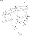
Fig. 1 is an appearance diagram of a relevant part of a vehicle provided with the slider-equipped window glass according to this embodiment. -
Fig. 2 is a cross sectional view of a relevant part of the slider-equipped window glass shown inFig. 1 . -
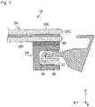
Fig. 3 is an enlarged cross sectional view of a relevant part of the slider-equipped window glass shown inFig. 2 . -
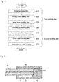
Fig. 4 is a flow chart showing the process for producing the slider-equipped window glass in this embodiment. -
Fig. 5 is an illustrative view of the primary mold setting step. -
Fig. 6 is an illustrative view of the inner layer molding step. -
Fig. 7 is an illustrative view of the secondary mold setting step. -
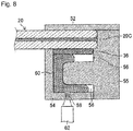
Fig. 8 is an illustrative view of the outer layer molding step. -
Fig. 9 is a cross sectional view of a relevant part of the slider-equipped window glass in another embodiment. - Hereinafter, with reference to the accompanying drawings, preferred embodiments of the slider-equipped window glass and the process for its production according to the present invention will be described. In each Fig., arrow A indicates the front side of the vehicle, arrow B indicates the upper side of the vehicle, and arrow C indicates the outside in the width direction of the vehicle.
- In
Fig. 1 , afront side door 14 of avehicle 12 is shown in which the slider-equippedwindow glass 10 according to this embodiment is mounted to be vertically movable up and down. On the rear side of thisfront side door 14, arear side door 18 is disposed via apillar 16. Also in thisrear side door 18, the slider-equipped window glass 10 (not shown) according to this embodiment is mounted to be movable up and down. - In this embodiment, description will be made with reference to a laminated glass as a
window glass 20 to constitute a slider-equippedwindow glass 10. Thiswindow glass 20 is constructed to have a roughly trapezoid shape having a circular arcupper edge 20A, a roughly horizontallower edge 20B, a roughly verticalrear edge 20C and afront edge 20D. Therear edge 20C and thefront edge 20D correspond to the two sides of the window glass of the present invention. - The
window glass 20 attached to each of thefront side door 14 and therear side door 18 is disposed so that when theengaging portion 26 of theslider 24 is engaged with the up-and-downmovement guide member 22 as shown in the cross sectional view ofFig. 2 , its vehicleouter surface 20E outside in the vehicle width direction would be flush with the vehicleouter surface 30A of a sash and with the vehicleouter surface 16A of apillar 16 as described later. The vehicleouter surface 30A of thesash 30 and the vehicleouter surface 16A of thepillar 16 correspond to the vehicle outer surface of the vehicle outside in the vehicle width direction in the present invention. Thus, according to the slider-equippedwindow glass 10 of this embodiment, it is possible to accomplish a flush surfaced construction. Further, the up-and-downmovement guide member 22 and theslider 24 will also be described later. - Returning to
Fig. 1 , the front side door 14 (likewise the rear side door 18) is provided with, in addition to the slider-equippedwindow glass 10, adoor panel 28 and the above-mentionedsash 30 being the window frame. Thedoor panel 28 constitutes a lower portion of thefront side door 14. Inside of thisdoor panel 28, a lifting and lowering device to move the slider-equippedwindow glass 10 up and down, is provided. - The
sash 30 is provided at an upper portion of thedoor panel 28, and awindow opening 32 is defined by thesash 30 and thedoor panel 28. The slider-equippedwindow glass 10 is moved up and down in the lifting and lowering direction (the up-and-down direction of the vehicle) along the rearvertical frame 30B of thesash 30. Thus, thewindow opening 32 will be closed and opened by the slider-equippedwindow glass 10. - The above-mentioned lifting and lowering device is provided with a motor (not shown) and a power transmission member (not shown) such as a link member or wire to transmit the power of the motor to the slider-equipped
window glass 10. This power transmission member is to be connected to each of a pair ofholders lower edge 20B of thewindow glass 20. - The above-mentioned
Fig. 2 is a cross sectional view of the relevant part of the slider-equippedwindow glass 10 in a state where the window opening 32 (seeFig. 1 ) is closed. As shown inFig. 2 , theslider 24 is attached to the vehicleinner surface 20F of therear edge 20C of thewindow glass 20. Thisslider 24 is attached along the up-and-down movement direction as shown inFig. 1 . Further, aslider 24 is attached also to the vehicleinner surface 20F of thefront edge 20D of thewindow glass 20, as the case requires. Thus, in this embodiment, a slider-equippedwindow glass 10 havingsliders 24 attached to the two sides of awindow glass 20, is shown. - As shown in
Fig. 3 , theslider 24 is an integrally molded product including aninner layer portion 36 and anouter layer portion 38. Theinner layer portion 36 is bonded to the vehicleinner surface 20F of thewindow glass 20, and theouter layer portion 38 is located at the vehicle inner side of theinner layer portion 36 and made of a material harder than theinner layer portion 36. Further, in theouter layer portion 38, a concaveengaging portion 26 to engage with the up-and-downmovement guide member 22, is formed. - Inside of the
engaging portion 26 of theouter layer portion 38, the convex up-and-downmovement guide member 22 shown inFigs. 2 and3 is inserted. Thus, theengaging portion 26 is engaged with the up-and-downmovement guide member 22. As shown inFig. 2 , the up-and-downmovement guide member 22 is attached along the rearvertical frame 30B of thesash 30. Further, as shown inFig. 1 , the up-and-downmovement guide member 22 is attached also to the frontvertical frame 30C of thesash 30. - Returning to
Fig. 3 , the material for theinner layer portion 36 is a thermoplastic elastomer with a low hardness as compared with an engineering plastic such as POM (polyacetal resin) and is a thermoplastic elastomer such as PP (polypropylene resin) or PVC (polyvinyl chloride). As exemplification, the hardness of each of the above materials is such that the Rockwell hardness (R scale) of POM is 120, the Rockwell hardness (A scale) of a thermoplastic elastomer containing PP as the base material (main material) is from 50 to 95, and the Shore A hardness of PVC is from 60 to 95. Further, in the case of forming theinner layer portion 36, it is preferred to form theinner layer portion 36 after applying a primer to the vehicleinner surface 20F of therear edge 20C of thewindow glass 20. It is thereby possible to increase the adhesion between thewindow glass 20 and theinner layer portion 36. - On the other hand, the material for the
outer layer portion 38 is a material having a higher hardness and strength than theinner layer portion 36, and an engineering plastic may be selected for use, but it is preferred to select the following resin. - That is, for the
slider 24 of this embodiment, theinner layer portion 36 and theouter layer portion 38 are formed by two-color molding in order to increase the quality and productivity of the slider-equippedwindow glass 10. That is, theslider 24 is a two-color molded product formed by two-color molding which includes forming aninner layer portion 36, followed by forming anouter layer portion 38 on the vehicle inner surface side of theinner layer portion 36. Therefore, as the material for theouter layer portion 38, in consideration of the integral moldability (adhesion) with theinner layer portion 36, it is preferred to select a thermoplastic elastomer containing fibers such as glass fibers or carbon fibers in the same PP or PVC as the material for theinner layer portion 36. - The slider-equipped
window glass 10 of this embodiment is an integrally molded product of thewindow glass 20, theinner layer portion 36 and theouter layer portion 38 of theslider 24 at the vehicleinner surface 20F of therear edge 20C and thefront edge 20D of awindow glass 20. Therefore, the slider-equippedwindow glass 10 can be formed without using the double sided adhesive tape or the adhesive. Since no adhesive is used, aging time for curing the adhesive is unnecessary, and there is no fear that theslider 24 peels from thewindow glass 20 due to deterioration of the adhesive or the like. Furthermore, since the slider-equippedwindow glass 10 can be formed without using the double sided adhesive tape or the adhesive, it is possible to be molded integrally with theslider 24 to thewindow glass 20 with a high precision (e.g. in a few hundred micron order). - Next, the process for producing a slider-equipped
window glass 10 of this embodiment will be described with reference to a flow chart shown inFig. 4 . The production process of this embodiment is a production process for attaching aslider 24 by two-color molding to the vehicleinner surface 20F of therear edge 20C of awindow glass 20. Further, since the production process for attaching aslider 24 to the vehicleinner surface 20F of thefront edge 20D of thewindow glass 20, is the same as the following production process, its description will be omitted. - As shown in
Fig. 4 , the production process of this embodiment includes a first molding step and a second molding step as largely divided. - The first molding step includes, in sequential order, a primer applying step (S10), a primary mold setting step (S20) of attaching a primary mold for an inner layer portion to a
window glass 20, an inner layer molding step (S30) of injecting molten PP (may be PVC) into the primary mold, and a primary de-molding step (S40) of dismounting the primary mold from thewindow glass 20. - The primer applying step (S10) is a step of applying a primer to the vehicle
inner surface 20F of therear edge 20C of thewindow glass 20. -
Fig. 5 is an illustrative view of the primary mold setting step (S20). InFig. 5 , a cross sectional view is shown in which a pair ofmolds window glass 20 where aslider 24 is to be attached. InFig. 5 , acavity space 44 to form aninner layer portion 36 is formed by the inner wall surfaces of the pair ofmolds injection inlet 46 to inject PP into thecavity space 44 is formed in themold 42. Here, inFig. 5 , an example is shown wherein the primary mold is constructed by a pair ofmolds Fig. 5 . - Next, in the inner layer molding step (S30), as shown in the illustrative view of
Fig. 6 , molten PP48 is injected into thecavity space 44 from theinjection inlet 46 by aninjection cylinder 50. Aninner layer portion 36 will thereby be formed on the vehicleinner surface 20F of therear edge 20C of thewindow glass 20. Thereafter, in the primary de-molding step (S40), themolds window glass 20. - On the other hand, the second molding step includes, in sequential order, a secondary mold setting step (S50) of attaching a secondary mold for the outer layer portion to the
window glass 20, an outer layer molding step (S60) of injecting molten PP (may be PVC) containing e.g. 30% of glass fibers into the secondary mold, and a secondary de-molding step (S70) of dismounting the secondary mold from thewindow glass 20. -
Fig. 7 is an illustrative view of the secondary mold setting step (S50). InFig. 7 , a cross sectional view is shown whereinmolds window glass 20 where aslider 24 is to be attached. InFig. 7 , acavity space 56 to form theouter layer portion 38 is formed by the inner wall surfaces of themolds injection inlet 58 to inject PP containing 30% of glass fibers into thecavity space 56 is formed in themold 54. Here, inFig. 7 , an example is shown wherein the secondary mold is constructed bymolds Fig. 7 . - Next, in the outer layer molding step (S60), as shown in the illustrative view of
Fig. 8 , molten PP60 containing 30% of glass fibers, is injected into thecavity space 56 from theinjection inlet 58 by aninjection cylinder 62. Anouter layer portion 38 is thereby integrally formed outside of theinner layer portion 36. Thereafter, in the secondary de-molding step (S70), themolds window glass 20. Thus, theslider 24 of the two-color molded product including theinner layer portion 36 and theouter layer portion 38 can be formed integrally with therear edge 20C of thewindow glass 20. - Here, in the outer layer molding step (S60) in this embodiment, PP of the same base material (main material) as the material for the
inner layer portion 36 is used, whereby molten PP60 containing 30% of glass fibers will be well heat-fused to theinner layer portion 36 made of PP. It is thus possible to construct aslider 24 having a high dimensional precision and a stabilized shape. The above-mentioned content (30%) of glass fibers is one to be set depending upon the hardness required for theouter layer portion 38, and as exemplification, it is set to be from 30% to 40%. Further, instead of glass fibers, carbon fibers may be incorporated to PP. - Accordingly, by the production process of this embodiment, the
window glass 20, theinner layer portion 36 and theouter layer portion 38 of theslider 24 are integrally molded by injection molding at the vehicleinner surface 20F of therear edge 20C and thefront edge 20D of awindow glass 20. Further, the production process of this embodiment, theslider 24 is formed by the two-color molding, whereby steps S10 to S70 can be carried out in a few minutes. Thus, theslider 24 is possible to be molded integrally with thewindow glass 20 in a short time. Therefore, according to the production process of this embodiment, as compared with Patent Documents 1 and 2, it is possible to increase the productivity of the slider-equipped window glass. - Further, according to the production process of this embodiment, since it is a process by two-color molding, it is possible to attach a
slider 24 to awindow glass 20 with a high precision (e.g. at a few hundred micron order). Furthermore, according to the production process of this embodiment, since there is no step to cause a positional displacement of the slider relative to the window glass as in Patent Documents 1 and 2, it is also possible to increase the quality of the slider-equippedwindow glass 10. - As described above, according to the slider-equipped
window glass 10 and the process for its production of this embodiment, it is possible to increase the productivity and quality of the slider-equippedwindow glass 10. - Further, the
slider 24 in this embodiment is composed of a softinner layer portion 36 and a hardouter layer portion 38, whereby even if a difference in the expansion degree is resulted between thewindow glass 20 and theouter layer portion 38 due to a difference in the linear expansion coefficient, such a difference may be absorbed as theinner layer portion 36 undergoes elastic deformation. Thus, a problem to be caused by a difference in the linear expansion coefficient between thewindow glass 20 and theouter layer portion 38, i.e. a problem of peeling of theslider 24 from thewindow glass 20, will not result. Accordingly, it is possible to increase the quality of the slider-equippedwindow glass 10. - Further, in the production process of this embodiment, by carrying out the first molding step and the second molding step as follows, it is possible to further shorten the production time of the slider-equipped
window glass 10. - That is, in the first molding step, in a preliminary step of the inner layer molding step (S30),
molds molten PP 48, and thereafter, the inner layer molding step (S30) is carried out. And, immediately after completion of the inner layer molding step (S30), themolds inner layer portion 36 in a short time. Likewise in the second molding step, in a preliminary step of the outer layer molding step (S60),molds molds outer layer portion 38 in a short time. By heating and cooling the primary mold and the secondary mold at the predetermined timings as described above, it is possible to shorten the molding time of theslider 24. Thus, it is possible to further shorten the production time of the slider-equippedwindow glass 10. - Here, in this embodiment, an example is shown wherein
sliders inner surfaces 20F in the vicinity of two sides (rear edge 20C andfront edge 20D) of awindow glass 20, but aslider 24 may be attached to an vehicleinner surface 20F in the vicinity of at least one side of awindow glass 20. - Further, in this embodiment, as the
window glass 20, a laminated glass was exemplified, but the window glass is not limited thereto and may, for example, be a single plate glass. - Further, as the
window glass 20, in addition to a non-tempered glass, a tempered glass may be used. The tempered glass may be an air-cooled tempered glass or a chemically tempered glass. In a case where a tempered glass is used for a single plate glass, in order to prevent scattering of glass pieces when broken, a scattering preventive film may be bonded on the surface of the single plate glass. On the other hand, in a case where a tempered glass is used for a laminated glass, the function of the scattering preventive film may be born by a known interlayer, so that the scattering preventive film will not be required. Such an interlayer of the laminated glass may, for example, be a known layer made of e.g. PVB (polyvinyl butyral) or EVA (ethylene vinyl acetate). - Further, in this embodiment, as shown in
Fig. 3 , a concave engagingportion 26 is formed on theslider 24 side, and the up-and-downmovement guide member 22 is formed to be convex, but the engagement mode is not limited thereto. For example, as shown in the cross sectional view of the slider-equippedwindow glass 10A in another embodiment shown inFig. 9 , a convexengaging portion 26A may be formed on theslider 24 side, and the up-and-downmovement guide member 22 side may be formed to be concave. - The entire disclosure of Japanese Patent Application No.
2017-236134 filed on December 8, 2017 - 10: Slider-equipped window glass, 10A: slider-equipped window glass, 12: vehicle, 14: front side door, 16: pillar, 18: rear side door, 20: window glass, 22: up-and-down movement guide member, 24: slider, 26: engaging portion, 26A: engaging portion, 28: door panel, 30: sash, 32: window opening, 34: holder, 36: inner layer portion, 38: outer layer portion, 40: mold, 42: mold, 44: cavity space, 46: injection inlet, 48: molten PP, 50: injection cylinder, 52: mold, 54: mold, 55: mold, 56: cavity space, 58: injection inlet, 60: PP containing 30% of glass fibers, 62: injection cylinder
Claims (10)
- A slider-equipped window glass comprising
a window glass mounted on a side door of a vehicle so as to be vertically movable up and down and having two sides, and
a slider attached to a vehicle inner surface of at least one of said two sides of the window glass, along the up-and-down movement direction, and being movable up and down along an up-and-down movement guide member fixed to said side door, wherein
said slider is an integrally molded product comprising an inner layer portion and an outer layer portion,
said inner layer portion is bonded to said vehicle inner surface of the window glass, said outer layer portion is located at the vehicle inner surface side of the inner layer portion and made of a material harder than said inner layer portion, and
said outer layer portion has an engaging portion to engage with said up-and-down movement guide member. - The slider-equipped window glass according to Claim 1, wherein the slider-equipped window glass is an integrally molded product of the window glass and the slider.
- The slider-equipped window glass according to Claim 1 or 2, wherein said slider is disposed at each of said two sides of the window glass.
- The slider-equipped window glass according to any one of Claims 1 to 3, wherein said engaging portion is made to be a concave portion or a convex portion.
- The slider-equipped window glass according to any one of Claims 1 to 4, wherein said inner layer portion of the slider is made of a thermoplastic elastomer, and said outer layer portion is made of a thermoplastic elastomer containing fibers.
- The slider-equipped window glass according to any one of Claims 1 to 5, wherein said window glass is a laminated glass or a single-plate glass.
- The slider-equipped window glass according to any one of Claims 1 to 6, wherein said slider is a two-color molded product comprising said inner layer portion and said outer layer portion.
- The slider-equipped window glass according to any one of Claims 1 to 7, wherein when said engaging portion of the slider is engaged with said up-and-down movement guide member, said slider-equipped window glass is disposed so that its vehicle outer surface outside in the vehicle width direction would be flush with the vehicle outer surface of the vehicle outside in the vehicle width direction.
- The slider-equipped window glass according to any one of Claims 1 to 7, wherein said slider-equipped window glass is provided on each of a front side door and a rear side door located adjacent in the front and rear direction of the vehicle, and said slider-equipped window glass provided on each of the front side door and the rear side door is disposed so that its vehicle outer surface outside in the vehicle width direction would be flush with the vehicle outer surface of the vehicle outside in the vehicle width direction.
- A process for producing a slider-equipped window glass comprising
a window glass mounted on a side door of a vehicle so as to be vertically movable up and down and having two sides, and
a slider attached to a vehicle inner surface of at least one of said two sides of the window glass, along the up-and-down movement direction, and being movable up and down along an up-and-down movement guide member fixed to said side door, said process comprising
a first molding step of forming an inner layer portion on said vehicle inner surface of said window glass, and
a second molding step of forming an outer layer portion harder than said inner layer portion, on the vehicle inner surface side of said inner layer portion, integrally with said inner layer portion, wherein
the second molding step includes a step of molding an engaging portion to engage with said up-and-down movement guide member, together with said outer layer portion.
Applications Claiming Priority (1)
| Application Number | Priority Date | Filing Date | Title |
|---|---|---|---|
| JP2017236134 | 2017-12-08 |
Publications (2)
| Publication Number | Publication Date |
|---|---|
| EP3498509A1 true EP3498509A1 (en) | 2019-06-19 |
| EP3498509B1 EP3498509B1 (en) | 2021-05-05 |
Family
ID=64604506
Family Applications (1)
| Application Number | Title | Priority Date | Filing Date |
|---|---|---|---|
| EP18210022.2A Active EP3498509B1 (en) | 2017-12-08 | 2018-12-04 | Slider-equipped window glass and process for its production |
Country Status (4)
| Country | Link |
|---|---|
| US (1) | US11104211B2 (en) |
| EP (1) | EP3498509B1 (en) |
| JP (1) | JP7147485B2 (en) |
| CN (1) | CN109895315B (en) |
Families Citing this family (4)
| Publication number | Priority date | Publication date | Assignee | Title |
|---|---|---|---|---|
| JP7095263B2 (en) * | 2017-11-10 | 2022-07-05 | 株式会社アイシン | Wind glass support structure for vehicle doors |
| FR3074830B1 (en) * | 2017-12-13 | 2024-01-19 | Saint Gobain | GLAZING, PARTICULARLY FOR AERONAUTICS, CAPABLE OF BEING BLOCKED IN ITS RECEPTION OPENING IN THE EVENT OF BREAKAGE |
| DE102020206401A1 (en) * | 2020-05-22 | 2021-11-25 | Motherson Innovations Company Limited | Vehicle strip device and vehicle with such a vehicle strip device |
| US11485201B2 (en) | 2020-11-12 | 2022-11-01 | Rivian Ip Holdings, Llc | Hidden division bar for a vehicle window |
Citations (3)
| Publication number | Priority date | Publication date | Assignee | Title |
|---|---|---|---|---|
| EP1464524A2 (en) * | 2003-04-02 | 2004-10-06 | HONDA MOTOR CO., Ltd. | Automotive windowpane support structure |
| JP2008001227A (en) | 2006-06-22 | 2008-01-10 | Asahi Glass Co Ltd | Support structure for vehicle window plate |
| EP3173270A1 (en) * | 2015-11-24 | 2017-05-31 | Toyota Jidosha Kabushiki Kaisha | Structure configured to raise and lower vehicle glass door |
Family Cites Families (33)
| Publication number | Priority date | Publication date | Assignee | Title |
|---|---|---|---|---|
| JPS57158481A (en) * | 1981-03-27 | 1982-09-30 | Asahi Glass Co Ltd | Method of forming lace or gasket |
| DE3153293C2 (en) * | 1981-12-11 | 1993-11-25 | Rockwell Golde Gmbh | Automatically pressing sealing arrangement for the window pane of a vertically movable vehicle window |
| DE3200322A1 (en) * | 1982-01-08 | 1983-07-28 | Adam Opel AG, 6090 Rüsselsheim | HEIGHT-ADJUSTABLE WINDOW WINDOW, ESPECIALLY FOR MOTOR VEHICLES |
| JPS63161017U (en) * | 1987-04-10 | 1988-10-20 | ||
| IT1210806B (en) * | 1987-06-16 | 1989-09-29 | Ferrari Eng | SUPPORT AND DRIVE STRUCTURE OF THE CRYSTALS OF A CAR BODY |
| IT1211298B (en) * | 1987-09-14 | 1989-10-12 | Fiat Auto Spa | WINDOW OF A VEHICLE DOOR |
| FR2634816B1 (en) * | 1988-07-28 | 1990-11-02 | Hutchinson | GUIDE SLIDE FOR MOBILE ICE, ESPECIALLY ICE OR AUTOMOTIVE WINDOW |
| FR2641025B1 (en) * | 1988-12-28 | 1995-05-24 | Mesnel Sa Ets | |
| JPH02179716A (en) * | 1988-12-29 | 1990-07-12 | Hashimoto Forming Ind Co Ltd | Manufacture of vertically moving window for automobile |
| IT1237689B (en) | 1989-12-15 | 1993-06-15 | Fiat Auto Spa | DOOR FOR VEHICLES AND METHOD FOR THE REALIZATION OF THE SAME. |
| US5613325A (en) * | 1995-12-22 | 1997-03-25 | Excel Industries, Inc. | Motor vehicle glazing units |
| JP3581307B2 (en) | 2000-10-19 | 2004-10-27 | トヨタ車体株式会社 | Window plate with frame |
| JP4057391B2 (en) | 2001-10-16 | 2008-03-05 | 株式会社ニフコ | Glass holder, connecting part, bonding method, and hot melt resin molding method |
| JP2004149045A (en) * | 2002-10-31 | 2004-05-27 | Honda Motor Co Ltd | Supporting structure of window glass of vehicle |
| US7024822B2 (en) * | 2004-03-04 | 2006-04-11 | Dura Global Technologies, Inc. | Articulating window hinges and articulating window assemblies |
| JP2005297602A (en) * | 2004-04-06 | 2005-10-27 | Honda Motor Co Ltd | Door sash structure |
| JP2006044360A (en) * | 2004-08-02 | 2006-02-16 | Toyoda Gosei Co Ltd | Glass run |
| US20060059799A1 (en) * | 2004-08-24 | 2006-03-23 | Cooper-Standard Automotive Inc. | Invisible division bar modular assembly |
| US20060225361A1 (en) * | 2005-04-06 | 2006-10-12 | Scheer Del W | Articulated window assembly with ball turret hinge |
| JP2006341693A (en) | 2005-06-08 | 2006-12-21 | Asahi Glass Co Ltd | Car window plate holding structure |
| GB2432870A (en) * | 2005-11-18 | 2007-06-06 | Gdx North America Inc | Sealing assemblies and methods of making them |
| DE102006053095A1 (en) * | 2006-11-10 | 2008-05-15 | Metzeler Automotive Profile Systems Gmbh | Guiding arrangement for a movable window pane, in particular of a motor vehicle |
| FR2956068B1 (en) * | 2010-02-08 | 2012-04-20 | Hutchinson | EXTERIOR COVER FOR AUTOMOTIVE VEHICLE DOOR FRAME, AND INCORPORATING SEALING MODULE |
| US20120025564A1 (en) * | 2010-07-28 | 2012-02-02 | Magna International Inc. | Flush Glass System Module |
| US8646215B2 (en) * | 2011-09-08 | 2014-02-11 | Ford Global Technologies, Llc | Flush glass assembly interfaces |
| US8561354B2 (en) * | 2011-09-08 | 2013-10-22 | Ford Global Technologies, Llc | Lower door structure for flush glass system |
| JP5846159B2 (en) | 2013-05-31 | 2016-01-20 | トヨタ自動車株式会社 | Window glass support structure |
| US10487342B2 (en) * | 2014-07-11 | 2019-11-26 | Genomatica, Inc. | Microorganisms and methods for the production of butadiene using acetyl-CoA |
| EP3183134B1 (en) * | 2015-11-02 | 2017-10-04 | Cooper Standard GmbH | Window assembly and vehicle door and vehicle featuring the window assembly |
| ES2692418T3 (en) * | 2015-11-02 | 2018-12-03 | Cooper Standard GmbH | Set of window, window glass, and window sealing profile |
| US10442281B2 (en) * | 2015-11-02 | 2019-10-15 | Cooper Standard GmbH | Window assembly, window pane, and window guiding profile |
| JP6396875B2 (en) * | 2015-11-05 | 2018-09-26 | トヨタ自動車株式会社 | Vehicle side door |
| JP7498116B2 (en) * | 2018-04-05 | 2024-06-11 | マルチベース・エスア | Thermoplastic Composition |
-
2018
- 2018-11-02 JP JP2018207120A patent/JP7147485B2/en active Active
- 2018-11-27 US US16/201,302 patent/US11104211B2/en active Active
- 2018-12-04 EP EP18210022.2A patent/EP3498509B1/en active Active
- 2018-12-07 CN CN201811494009.7A patent/CN109895315B/en active Active
Patent Citations (4)
| Publication number | Priority date | Publication date | Assignee | Title |
|---|---|---|---|---|
| EP1464524A2 (en) * | 2003-04-02 | 2004-10-06 | HONDA MOTOR CO., Ltd. | Automotive windowpane support structure |
| JP2008001227A (en) | 2006-06-22 | 2008-01-10 | Asahi Glass Co Ltd | Support structure for vehicle window plate |
| EP3173270A1 (en) * | 2015-11-24 | 2017-05-31 | Toyota Jidosha Kabushiki Kaisha | Structure configured to raise and lower vehicle glass door |
| JP2017094921A (en) | 2015-11-24 | 2017-06-01 | トヨタ自動車株式会社 | Door glass lift structure for vehicle |
Also Published As
| Publication number | Publication date |
|---|---|
| CN109895315B (en) | 2022-09-30 |
| CN109895315A (en) | 2019-06-18 |
| US20190176579A1 (en) | 2019-06-13 |
| US11104211B2 (en) | 2021-08-31 |
| JP2019105153A (en) | 2019-06-27 |
| JP7147485B2 (en) | 2022-10-05 |
| EP3498509B1 (en) | 2021-05-05 |
Similar Documents
| Publication | Publication Date | Title |
|---|---|---|
| US10851575B2 (en) | Holder-equipped window glass and process for its production | |
| US11104211B2 (en) | Slider-equipped window glass and process for its production | |
| US4925511A (en) | Method of fitting plate member with supportive or protective member of molded resin | |
| US11673453B2 (en) | Fixed window glass having resin frame body, and method for manufacturing same | |
| US20200298690A1 (en) | Encapsulation assembly for automotive glass | |
| US10195928B2 (en) | Quarter window assembly for a vehicle door and method of making the assembly | |
| KR101002223B1 (en) | Method for producing vehicle windows with decorative braids and Vehicle windows with decorative braids | |
| CN103978871B (en) | Quarter window and injection molding assembly forming method, guide rail, quarter window, car door and automobile | |
| GB2513620A (en) | A motor vehicle plastic body panel | |
| JP2020513361A (en) | Sliding laminated glazing unit with inward protruding edge | |
| JP2019535616A (en) | Sliding laminated glazing unit with inner protruding edge | |
| US12077035B2 (en) | Window unit comprising a glazing panel and a frame | |
| EP3795324B1 (en) | Method and device to produce a window surround for a vehicle and window surround for a vehicle | |
| EP3056367B1 (en) | Vehicle glass guiding and sealing element | |
| US20220152892A1 (en) | Method for manufacturing resin-framed glass plate | |
| EP3802174A1 (en) | Window unit comprising a glazing panel and a frame | |
| JP7441427B2 (en) | window glass with channel | |
| CN111152631B (en) | Vehicle window device, and method for manufacturing vehicle window device | |
| EP3566848B1 (en) | Glass run channel assembly for a vehicle and method for forming such a glass run channel assembly |
Legal Events
| Date | Code | Title | Description |
|---|---|---|---|
| PUAI | Public reference made under article 153(3) epc to a published international application that has entered the european phase |
Free format text: ORIGINAL CODE: 0009012 |
|
| STAA | Information on the status of an ep patent application or granted ep patent |
Free format text: STATUS: THE APPLICATION HAS BEEN PUBLISHED |
|
| AK | Designated contracting states |
Kind code of ref document: A1 Designated state(s): AL AT BE BG CH CY CZ DE DK EE ES FI FR GB GR HR HU IE IS IT LI LT LU LV MC MK MT NL NO PL PT RO RS SE SI SK SM TR |
|
| AX | Request for extension of the european patent |
Extension state: BA ME |
|
| STAA | Information on the status of an ep patent application or granted ep patent |
Free format text: STATUS: REQUEST FOR EXAMINATION WAS MADE |
|
| 17P | Request for examination filed |
Effective date: 20191219 |
|
| RBV | Designated contracting states (corrected) |
Designated state(s): AL AT BE BG CH CY CZ DE DK EE ES FI FR GB GR HR HU IE IS IT LI LT LU LV MC MK MT NL NO PL PT RO RS SE SI SK SM TR |
|
| GRAP | Despatch of communication of intention to grant a patent |
Free format text: ORIGINAL CODE: EPIDOSNIGR1 |
|
| STAA | Information on the status of an ep patent application or granted ep patent |
Free format text: STATUS: GRANT OF PATENT IS INTENDED |
|
| INTG | Intention to grant announced |
Effective date: 20201218 |
|
| GRAS | Grant fee paid |
Free format text: ORIGINAL CODE: EPIDOSNIGR3 |
|
| GRAA | (expected) grant |
Free format text: ORIGINAL CODE: 0009210 |
|
| STAA | Information on the status of an ep patent application or granted ep patent |
Free format text: STATUS: THE PATENT HAS BEEN GRANTED |
|
| AK | Designated contracting states |
Kind code of ref document: B1 Designated state(s): AL AT BE BG CH CY CZ DE DK EE ES FI FR GB GR HR HU IE IS IT LI LT LU LV MC MK MT NL NO PL PT RO RS SE SI SK SM TR |
|
| REG | Reference to a national code |
Ref country code: GB Ref legal event code: FG4D |
|
| REG | Reference to a national code |
Ref country code: CH Ref legal event code: EP |
|
| REG | Reference to a national code |
Ref country code: AT Ref legal event code: REF Ref document number: 1389379 Country of ref document: AT Kind code of ref document: T Effective date: 20210515 |
|
| REG | Reference to a national code |
Ref country code: IE Ref legal event code: FG4D |
|
| REG | Reference to a national code |
Ref country code: DE Ref legal event code: R096 Ref document number: 602018016576 Country of ref document: DE |
|
| REG | Reference to a national code |
Ref country code: LT Ref legal event code: MG9D |
|
| REG | Reference to a national code |
Ref country code: AT Ref legal event code: MK05 Ref document number: 1389379 Country of ref document: AT Kind code of ref document: T Effective date: 20210505 |
|
| PG25 | Lapsed in a contracting state [announced via postgrant information from national office to epo] |
Ref country code: FI Free format text: LAPSE BECAUSE OF FAILURE TO SUBMIT A TRANSLATION OF THE DESCRIPTION OR TO PAY THE FEE WITHIN THE PRESCRIBED TIME-LIMIT Effective date: 20210505 Ref country code: LT Free format text: LAPSE BECAUSE OF FAILURE TO SUBMIT A TRANSLATION OF THE DESCRIPTION OR TO PAY THE FEE WITHIN THE PRESCRIBED TIME-LIMIT Effective date: 20210505 Ref country code: HR Free format text: LAPSE BECAUSE OF FAILURE TO SUBMIT A TRANSLATION OF THE DESCRIPTION OR TO PAY THE FEE WITHIN THE PRESCRIBED TIME-LIMIT Effective date: 20210505 Ref country code: AT Free format text: LAPSE BECAUSE OF FAILURE TO SUBMIT A TRANSLATION OF THE DESCRIPTION OR TO PAY THE FEE WITHIN THE PRESCRIBED TIME-LIMIT Effective date: 20210505 Ref country code: BG Free format text: LAPSE BECAUSE OF FAILURE TO SUBMIT A TRANSLATION OF THE DESCRIPTION OR TO PAY THE FEE WITHIN THE PRESCRIBED TIME-LIMIT Effective date: 20210805 |
|
| PG25 | Lapsed in a contracting state [announced via postgrant information from national office to epo] |
Ref country code: IS Free format text: LAPSE BECAUSE OF FAILURE TO SUBMIT A TRANSLATION OF THE DESCRIPTION OR TO PAY THE FEE WITHIN THE PRESCRIBED TIME-LIMIT Effective date: 20210905 Ref country code: GR Free format text: LAPSE BECAUSE OF FAILURE TO SUBMIT A TRANSLATION OF THE DESCRIPTION OR TO PAY THE FEE WITHIN THE PRESCRIBED TIME-LIMIT Effective date: 20210806 Ref country code: LV Free format text: LAPSE BECAUSE OF FAILURE TO SUBMIT A TRANSLATION OF THE DESCRIPTION OR TO PAY THE FEE WITHIN THE PRESCRIBED TIME-LIMIT Effective date: 20210505 Ref country code: PL Free format text: LAPSE BECAUSE OF FAILURE TO SUBMIT A TRANSLATION OF THE DESCRIPTION OR TO PAY THE FEE WITHIN THE PRESCRIBED TIME-LIMIT Effective date: 20210505 Ref country code: PT Free format text: LAPSE BECAUSE OF FAILURE TO SUBMIT A TRANSLATION OF THE DESCRIPTION OR TO PAY THE FEE WITHIN THE PRESCRIBED TIME-LIMIT Effective date: 20210906 Ref country code: NO Free format text: LAPSE BECAUSE OF FAILURE TO SUBMIT A TRANSLATION OF THE DESCRIPTION OR TO PAY THE FEE WITHIN THE PRESCRIBED TIME-LIMIT Effective date: 20210805 Ref country code: SE Free format text: LAPSE BECAUSE OF FAILURE TO SUBMIT A TRANSLATION OF THE DESCRIPTION OR TO PAY THE FEE WITHIN THE PRESCRIBED TIME-LIMIT Effective date: 20210505 Ref country code: RS Free format text: LAPSE BECAUSE OF FAILURE TO SUBMIT A TRANSLATION OF THE DESCRIPTION OR TO PAY THE FEE WITHIN THE PRESCRIBED TIME-LIMIT Effective date: 20210505 |
|
| REG | Reference to a national code |
Ref country code: NL Ref legal event code: MP Effective date: 20210505 |
|
| PG25 | Lapsed in a contracting state [announced via postgrant information from national office to epo] |
Ref country code: NL Free format text: LAPSE BECAUSE OF FAILURE TO SUBMIT A TRANSLATION OF THE DESCRIPTION OR TO PAY THE FEE WITHIN THE PRESCRIBED TIME-LIMIT Effective date: 20210505 |
|
| PG25 | Lapsed in a contracting state [announced via postgrant information from national office to epo] |
Ref country code: SM Free format text: LAPSE BECAUSE OF FAILURE TO SUBMIT A TRANSLATION OF THE DESCRIPTION OR TO PAY THE FEE WITHIN THE PRESCRIBED TIME-LIMIT Effective date: 20210505 Ref country code: SK Free format text: LAPSE BECAUSE OF FAILURE TO SUBMIT A TRANSLATION OF THE DESCRIPTION OR TO PAY THE FEE WITHIN THE PRESCRIBED TIME-LIMIT Effective date: 20210505 Ref country code: ES Free format text: LAPSE BECAUSE OF FAILURE TO SUBMIT A TRANSLATION OF THE DESCRIPTION OR TO PAY THE FEE WITHIN THE PRESCRIBED TIME-LIMIT Effective date: 20210505 Ref country code: EE Free format text: LAPSE BECAUSE OF FAILURE TO SUBMIT A TRANSLATION OF THE DESCRIPTION OR TO PAY THE FEE WITHIN THE PRESCRIBED TIME-LIMIT Effective date: 20210505 Ref country code: RO Free format text: LAPSE BECAUSE OF FAILURE TO SUBMIT A TRANSLATION OF THE DESCRIPTION OR TO PAY THE FEE WITHIN THE PRESCRIBED TIME-LIMIT Effective date: 20210505 Ref country code: DK Free format text: LAPSE BECAUSE OF FAILURE TO SUBMIT A TRANSLATION OF THE DESCRIPTION OR TO PAY THE FEE WITHIN THE PRESCRIBED TIME-LIMIT Effective date: 20210505 Ref country code: CZ Free format text: LAPSE BECAUSE OF FAILURE TO SUBMIT A TRANSLATION OF THE DESCRIPTION OR TO PAY THE FEE WITHIN THE PRESCRIBED TIME-LIMIT Effective date: 20210505 |
|
| REG | Reference to a national code |
Ref country code: DE Ref legal event code: R097 Ref document number: 602018016576 Country of ref document: DE |
|
| PLBE | No opposition filed within time limit |
Free format text: ORIGINAL CODE: 0009261 |
|
| STAA | Information on the status of an ep patent application or granted ep patent |
Free format text: STATUS: NO OPPOSITION FILED WITHIN TIME LIMIT |
|
| 26N | No opposition filed |
Effective date: 20220208 |
|
| PG25 | Lapsed in a contracting state [announced via postgrant information from national office to epo] |
Ref country code: IS Free format text: LAPSE BECAUSE OF FAILURE TO SUBMIT A TRANSLATION OF THE DESCRIPTION OR TO PAY THE FEE WITHIN THE PRESCRIBED TIME-LIMIT Effective date: 20210905 Ref country code: AL Free format text: LAPSE BECAUSE OF FAILURE TO SUBMIT A TRANSLATION OF THE DESCRIPTION OR TO PAY THE FEE WITHIN THE PRESCRIBED TIME-LIMIT Effective date: 20210505 |
|
| PG25 | Lapsed in a contracting state [announced via postgrant information from national office to epo] |
Ref country code: MC Free format text: LAPSE BECAUSE OF FAILURE TO SUBMIT A TRANSLATION OF THE DESCRIPTION OR TO PAY THE FEE WITHIN THE PRESCRIBED TIME-LIMIT Effective date: 20210505 Ref country code: IT Free format text: LAPSE BECAUSE OF FAILURE TO SUBMIT A TRANSLATION OF THE DESCRIPTION OR TO PAY THE FEE WITHIN THE PRESCRIBED TIME-LIMIT Effective date: 20210505 |
|
| REG | Reference to a national code |
Ref country code: CH Ref legal event code: PL |
|
| REG | Reference to a national code |
Ref country code: BE Ref legal event code: MM Effective date: 20211231 |
|
| PG25 | Lapsed in a contracting state [announced via postgrant information from national office to epo] |
Ref country code: LU Free format text: LAPSE BECAUSE OF NON-PAYMENT OF DUE FEES Effective date: 20211204 Ref country code: IE Free format text: LAPSE BECAUSE OF NON-PAYMENT OF DUE FEES Effective date: 20211204 |
|
| PG25 | Lapsed in a contracting state [announced via postgrant information from national office to epo] |
Ref country code: FR Free format text: LAPSE BECAUSE OF NON-PAYMENT OF DUE FEES Effective date: 20211231 Ref country code: BE Free format text: LAPSE BECAUSE OF NON-PAYMENT OF DUE FEES Effective date: 20211231 |
|
| PG25 | Lapsed in a contracting state [announced via postgrant information from national office to epo] |
Ref country code: LI Free format text: LAPSE BECAUSE OF NON-PAYMENT OF DUE FEES Effective date: 20211231 Ref country code: CH Free format text: LAPSE BECAUSE OF NON-PAYMENT OF DUE FEES Effective date: 20211231 |
|
| PG25 | Lapsed in a contracting state [announced via postgrant information from national office to epo] |
Ref country code: CY Free format text: LAPSE BECAUSE OF FAILURE TO SUBMIT A TRANSLATION OF THE DESCRIPTION OR TO PAY THE FEE WITHIN THE PRESCRIBED TIME-LIMIT Effective date: 20210505 |
|
| PG25 | Lapsed in a contracting state [announced via postgrant information from national office to epo] |
Ref country code: HU Free format text: LAPSE BECAUSE OF FAILURE TO SUBMIT A TRANSLATION OF THE DESCRIPTION OR TO PAY THE FEE WITHIN THE PRESCRIBED TIME-LIMIT; INVALID AB INITIO Effective date: 20181204 |
|
| GBPC | Gb: european patent ceased through non-payment of renewal fee |
Effective date: 20221204 |
|
| PG25 | Lapsed in a contracting state [announced via postgrant information from national office to epo] |
Ref country code: GB Free format text: LAPSE BECAUSE OF NON-PAYMENT OF DUE FEES Effective date: 20221204 |
|
| PG25 | Lapsed in a contracting state [announced via postgrant information from national office to epo] |
Ref country code: MK Free format text: LAPSE BECAUSE OF FAILURE TO SUBMIT A TRANSLATION OF THE DESCRIPTION OR TO PAY THE FEE WITHIN THE PRESCRIBED TIME-LIMIT Effective date: 20210505 |
|
| PG25 | Lapsed in a contracting state [announced via postgrant information from national office to epo] |
Ref country code: MT Free format text: LAPSE BECAUSE OF FAILURE TO SUBMIT A TRANSLATION OF THE DESCRIPTION OR TO PAY THE FEE WITHIN THE PRESCRIBED TIME-LIMIT Effective date: 20210505 |
|
| PG25 | Lapsed in a contracting state [announced via postgrant information from national office to epo] |
Ref country code: TR Free format text: LAPSE BECAUSE OF FAILURE TO SUBMIT A TRANSLATION OF THE DESCRIPTION OR TO PAY THE FEE WITHIN THE PRESCRIBED TIME-LIMIT Effective date: 20210505 |
|
| PGFP | Annual fee paid to national office [announced via postgrant information from national office to epo] |
Ref country code: DE Payment date: 20251211 Year of fee payment: 8 |