EP3498359A1 - Filterelement und zugehörige filtereinrichtung - Google Patents
Filterelement und zugehörige filtereinrichtung Download PDFInfo
- Publication number
- EP3498359A1 EP3498359A1 EP18206276.0A EP18206276A EP3498359A1 EP 3498359 A1 EP3498359 A1 EP 3498359A1 EP 18206276 A EP18206276 A EP 18206276A EP 3498359 A1 EP3498359 A1 EP 3498359A1
- Authority
- EP
- European Patent Office
- Prior art keywords
- filter
- filter element
- centering elements
- positioning
- end plate
- Prior art date
- Legal status (The legal status is an assumption and is not a legal conclusion. Google has not performed a legal analysis and makes no representation as to the accuracy of the status listed.)
- Granted
Links
Images

Classifications
-
- F—MECHANICAL ENGINEERING; LIGHTING; HEATING; WEAPONS; BLASTING
- F02—COMBUSTION ENGINES; HOT-GAS OR COMBUSTION-PRODUCT ENGINE PLANTS
- F02M—SUPPLYING COMBUSTION ENGINES IN GENERAL WITH COMBUSTIBLE MIXTURES OR CONSTITUENTS THEREOF
- F02M35/00—Combustion-air cleaners, air intakes, intake silencers, or induction systems specially adapted for, or arranged on, internal-combustion engines
- F02M35/02—Air cleaners
- F02M35/024—Air cleaners using filters, e.g. moistened
- F02M35/02475—Air cleaners using filters, e.g. moistened characterised by the shape of the filter element
- F02M35/02483—Cylindrical, conical, oval, spherical or the like filter elements; wounded filter elements
-
- B—PERFORMING OPERATIONS; TRANSPORTING
- B01—PHYSICAL OR CHEMICAL PROCESSES OR APPARATUS IN GENERAL
- B01D—SEPARATION
- B01D29/00—Filters with filtering elements stationary during filtration, e.g. pressure or suction filters, not covered by groups B01D24/00 - B01D27/00; Filtering elements therefor
- B01D29/11—Filters with filtering elements stationary during filtration, e.g. pressure or suction filters, not covered by groups B01D24/00 - B01D27/00; Filtering elements therefor with bag, cage, hose, tube, sleeve or like filtering elements
- B01D29/13—Supported filter elements
- B01D29/15—Supported filter elements arranged for inward flow filtration
- B01D29/21—Supported filter elements arranged for inward flow filtration with corrugated, folded or wound sheets
-
- B—PERFORMING OPERATIONS; TRANSPORTING
- B01—PHYSICAL OR CHEMICAL PROCESSES OR APPARATUS IN GENERAL
- B01D—SEPARATION
- B01D35/00—Filtering devices having features not specifically covered by groups B01D24/00 - B01D33/00, or for applications not specifically covered by groups B01D24/00 - B01D33/00; Auxiliary devices for filtration; Filter housing constructions
- B01D35/14—Safety devices specially adapted for filtration; Devices for indicating clogging
- B01D35/153—Anti-leakage or anti-return valves
-
- B—PERFORMING OPERATIONS; TRANSPORTING
- B01—PHYSICAL OR CHEMICAL PROCESSES OR APPARATUS IN GENERAL
- B01D—SEPARATION
- B01D35/00—Filtering devices having features not specifically covered by groups B01D24/00 - B01D33/00, or for applications not specifically covered by groups B01D24/00 - B01D33/00; Auxiliary devices for filtration; Filter housing constructions
- B01D35/16—Cleaning-out devices, e.g. for removing the cake from the filter casing or for evacuating the last remnants of liquid
-
- B—PERFORMING OPERATIONS; TRANSPORTING
- B01—PHYSICAL OR CHEMICAL PROCESSES OR APPARATUS IN GENERAL
- B01D—SEPARATION
- B01D46/00—Filters or filtering processes specially modified for separating dispersed particles from gases or vapours
- B01D46/0084—Filters or filtering processes specially modified for separating dispersed particles from gases or vapours provided with safety means
- B01D46/0087—Bypass or safety valves
-
- F—MECHANICAL ENGINEERING; LIGHTING; HEATING; WEAPONS; BLASTING
- F01—MACHINES OR ENGINES IN GENERAL; ENGINE PLANTS IN GENERAL; STEAM ENGINES
- F01M—LUBRICATING OF MACHINES OR ENGINES IN GENERAL; LUBRICATING INTERNAL COMBUSTION ENGINES; CRANKCASE VENTILATING
- F01M1/00—Pressure lubrication
- F01M1/10—Lubricating systems characterised by the provision therein of lubricant venting or purifying means, e.g. of filters
-
- F—MECHANICAL ENGINEERING; LIGHTING; HEATING; WEAPONS; BLASTING
- F01—MACHINES OR ENGINES IN GENERAL; ENGINE PLANTS IN GENERAL; STEAM ENGINES
- F01M—LUBRICATING OF MACHINES OR ENGINES IN GENERAL; LUBRICATING INTERNAL COMBUSTION ENGINES; CRANKCASE VENTILATING
- F01M11/00—Component parts, details or accessories, not provided for in, or of interest apart from, groups F01M1/00 - F01M9/00
- F01M11/03—Mounting or connecting of lubricant purifying means relative to the machine or engine; Details of lubricant purifying means
-
- F—MECHANICAL ENGINEERING; LIGHTING; HEATING; WEAPONS; BLASTING
- F02—COMBUSTION ENGINES; HOT-GAS OR COMBUSTION-PRODUCT ENGINE PLANTS
- F02M—SUPPLYING COMBUSTION ENGINES IN GENERAL WITH COMBUSTIBLE MIXTURES OR CONSTITUENTS THEREOF
- F02M37/00—Apparatus or systems for feeding liquid fuel from storage containers to carburettors or fuel-injection apparatus; Arrangements for purifying liquid fuel specially adapted for, or arranged on, internal-combustion engines
- F02M37/22—Arrangements for purifying liquid fuel specially adapted for, or arranged on, internal-combustion engines, e.g. arrangements in the feeding system
- F02M37/32—Arrangements for purifying liquid fuel specially adapted for, or arranged on, internal-combustion engines, e.g. arrangements in the feeding system characterised by filters or filter arrangements
- F02M37/42—Installation or removal of filters
-
- F—MECHANICAL ENGINEERING; LIGHTING; HEATING; WEAPONS; BLASTING
- F02—COMBUSTION ENGINES; HOT-GAS OR COMBUSTION-PRODUCT ENGINE PLANTS
- F02M—SUPPLYING COMBUSTION ENGINES IN GENERAL WITH COMBUSTIBLE MIXTURES OR CONSTITUENTS THEREOF
- F02M37/00—Apparatus or systems for feeding liquid fuel from storage containers to carburettors or fuel-injection apparatus; Arrangements for purifying liquid fuel specially adapted for, or arranged on, internal-combustion engines
- F02M37/22—Arrangements for purifying liquid fuel specially adapted for, or arranged on, internal-combustion engines, e.g. arrangements in the feeding system
- F02M37/32—Arrangements for purifying liquid fuel specially adapted for, or arranged on, internal-combustion engines, e.g. arrangements in the feeding system characterised by filters or filter arrangements
- F02M37/50—Filters arranged in or on fuel tanks
-
- B—PERFORMING OPERATIONS; TRANSPORTING
- B01—PHYSICAL OR CHEMICAL PROCESSES OR APPARATUS IN GENERAL
- B01D—SEPARATION
- B01D2201/00—Details relating to filtering apparatus
- B01D2201/29—Filter cartridge constructions
- B01D2201/291—End caps
-
- B—PERFORMING OPERATIONS; TRANSPORTING
- B01—PHYSICAL OR CHEMICAL PROCESSES OR APPARATUS IN GENERAL
- B01D—SEPARATION
- B01D2201/00—Details relating to filtering apparatus
- B01D2201/31—Other construction details
- B01D2201/316—Standpipes
-
- B—PERFORMING OPERATIONS; TRANSPORTING
- B01—PHYSICAL OR CHEMICAL PROCESSES OR APPARATUS IN GENERAL
- B01D—SEPARATION
- B01D2201/00—Details relating to filtering apparatus
- B01D2201/40—Special measures for connecting different parts of the filter
- B01D2201/4015—Bayonet connecting means
-
- B—PERFORMING OPERATIONS; TRANSPORTING
- B01—PHYSICAL OR CHEMICAL PROCESSES OR APPARATUS IN GENERAL
- B01D—SEPARATION
- B01D2201/00—Details relating to filtering apparatus
- B01D2201/40—Special measures for connecting different parts of the filter
- B01D2201/4046—Means for avoiding false mounting of different parts
-
- B—PERFORMING OPERATIONS; TRANSPORTING
- B01—PHYSICAL OR CHEMICAL PROCESSES OR APPARATUS IN GENERAL
- B01D—SEPARATION
- B01D2279/00—Filters adapted for separating dispersed particles from gases or vapours specially modified for specific uses
- B01D2279/60—Filters adapted for separating dispersed particles from gases or vapours specially modified for specific uses for the intake of internal combustion engines or turbines
-
- F—MECHANICAL ENGINEERING; LIGHTING; HEATING; WEAPONS; BLASTING
- F01—MACHINES OR ENGINES IN GENERAL; ENGINE PLANTS IN GENERAL; STEAM ENGINES
- F01M—LUBRICATING OF MACHINES OR ENGINES IN GENERAL; LUBRICATING INTERNAL COMBUSTION ENGINES; CRANKCASE VENTILATING
- F01M11/00—Component parts, details or accessories, not provided for in, or of interest apart from, groups F01M1/00 - F01M9/00
- F01M11/03—Mounting or connecting of lubricant purifying means relative to the machine or engine; Details of lubricant purifying means
- F01M2011/031—Mounting or connecting of lubricant purifying means relative to the machine or engine; Details of lubricant purifying means characterised by mounting means
Definitions
- the present invention relates to a filter element with an annular filter body of a filter material surrounding a cylindrical interior, according to the preamble of claim 1.
- the invention also relates to a filter device with at least one such filter element.
- a generic filter element in particular an air filter for a fresh air system of a vehicle and / or an internal combustion engine known, which has an annular filter body of a filter material. Also provided are an inner frame, on which the filter body is supported radially on the inside, and an upper end plate, which is arranged axially on the filter body and has a central disc opening.
- a liquid filter with a replaceable and a filter medium having filter cartridge wherein the liquid filter has a filter bypass valve, which opens when exceeding a predetermined liquid pressure and allows fluid flow from the raw to the clean side of the filter, bypassing the filter medium.
- the filter bypass valve has a movable valve body and a sealing surface associated therewith, the latter being arranged on the exchangeable filter insert and surrounding a valve opening.
- the valve body is also associated with a projection which extends through the valve opening. This should allow an improved flow of the filter bypass valve can be achieved.
- Filter devices for internal combustion engines usually consist of a filter housing and a replaceable in case of service filter element. Just With complex formed filter elements, it can cause problems when installing the filter element in the housing, since the filter element is not properly guided in the housing. In particular, a misalignment of the filter element relative to the function carrier or to the filter housing may result during installation, which can cause jamming and, under certain circumstances, a material break on the filter element or on the function carrier or on the filter housing.
- the present invention therefore deals with the problem of providing an improved or at least one alternative embodiment for a filter element of the generic type, which overcomes in particular the disadvantages known from the prior art and in particular allows a simplified installation in a filter housing of a filter device.
- the present invention is based on the general idea to provide special centering on a known filter element in the region of an upper end plate or an inner frame in the region of the upper end plate, which cause positive centering and thus forced operation of the filter element when installed in a filter housing a filter device and thereby Prevent tilting of the filter element relative to a filter housing or a riser in the filter housing, which in particular damage to the riser or the filter element can be reliably prevented.
- a positioning web is also provided in the region of the upper end plate and / or on the inner frame, the one Drehauscardicardi the filter element and thus a reliable insertion of a pin of the filter element in an associated idle channel of the filter device causes.
- the filter element according to the invention which may be, for example, an air filter, an oil filter or a fuel filter of a vehicle and / or an internal combustion engine, has an annular filter body of a filter material surrounding a cylindrical interior. Also provided are an inner frame on which the filter body is supported radially on the inside and an upper end plate, which is arranged axially on the filter body and which has a central first disc opening. In addition, the filter element has a lower end plate, which is also arranged axially on the filter body and which also has a central disc opening, which is referred to as the second disc opening, and on which an eccentrically arranged or axially projecting pin for closing an idle channel is arranged.
- a plurality of circumferentially distributed about the first disc opening arranged and axially protruding into the interior centering elements are provided, the upper end plate facing away from the longitudinal ends are chamfered such that an axial length of the centering radially inside is smaller than radially outside.
- the centering thus have a slope.
- a positioning web is provided which is arranged on the upper end disk and / or on the inner frame in the circumferential direction between two centering elements and which extends parallel to these.
- both the centering elements and the positioning element are produced in the plastic injection molding process, since in this case a common production, for example, of the upper end disk and / or the inner frame is made possible together with the centering elements or the positioning web.
- the centering elements and / or the positioning web can be executed on a separate component within the assembly. It is conceivable, in particular, for the centering elements and / or the positioning web to be designed as separate components which are connected, in particular clipped or glued, to the end disk and / or the inner frame.
- the positioning web is designed to be shorter in the axial direction than the centering elements. This offers the great advantage that, first, when the filter element is inserted into a filter housing of a filter device, centering of the filter element takes place via the centering elements, before the positioning web interacts with a positioning contour arranged, for example, in a standpipe of a function carrier. It is thus enforced by the inventively shorter design of the positioning web already pre-straightening of the filter element relative to the riser or relative to the function carrier or relative to the filter housing, whereby the installation can be simplified.
- At least three, preferably four, six or more centering elements are provided. At least three centering elements are required to effect a reliable centering of the filter element relative to the riser or relative to the filter housing of the filter device.
- the provision of at least three centering elements offers the possibility of a particularly resource-saving and cost / space-saving production.
- an axially projecting nozzle is arranged on the upper end disk of the filter element, wherein at least the centering elements extend into the nozzle.
- the invention is further based on the general idea of specifying a filter device, in particular an air filter, an oil filter or a fuel filter of a motor vehicle and / or an internal combustion engine, with at least one filter element described in the preceding paragraphs, wherein a riser pipe is arranged in a filter housing of the filter device which, for example, acts as a clean channel and which has a positioning contour, for example in the form of a cannula-like bevel, on a free longitudinal end facing the upper end plate.
- An inner diameter of the centering elements substantially corresponds to an outer diameter of the riser pipe, whereby the guide function described in the previous paragraph can be realized.
- a Drehauscardi the filter element can be forced relative to the filter housing of the filter device, whereby a flush alignment of the pin of the filter element relative to an idle channel in the filter housing is comparatively easy to implement.
- an axial groove for receiving the positioning web is arranged at a lowest point of the positioning contour.
- the positioning web of the filter element slides along the positioning contour on the riser until the positioning web is arranged in alignment with the axial groove of the positioning contour and can be inserted into it.
- the filter element side pin is aligned in the axial direction to the filter housing side idle channel, so that introduced by an axial displacement of the filter element relative to the filter housing the pin in the idle channel and the positioning in the axial groove can be.
- other positioning contours are theoretically conceivable, for example. In the manner of a helix, at the lowest point of the axial groove is arranged.
- An inventive filter element 1 which may be formed, for example, as an air filter, as an oil filter or as a fuel filter of a vehicle and / or an internal combustion engine, an annular filter body 2 of a filter material 3, which has a cylindrical interior 4 (see Fig. 2 and 3 ) surrounds. Also provided is an inner frame 5, on which the filter body 2 is supported radially inward.
- To the top filter element 1 of the invention is completed in a known manner via an upper end plate 6, which is arranged axially on the filter body 2 and has a central first disc opening 7. Down in the axial direction of the (ring) filter element 1, the filter body 2 is closed by a lower end plate 8, which has a central second disc opening 7 '.
- a plurality of circumferentially distributed around the first disc opening 7 and axially projecting into the interior 4 centering elements 9 are now provided, the upper end plate 6 facing away from the longitudinal ends are chamfered and thereby have a slope 10, so that an axial length of the centering elements 9 radially inside is smaller than radially outside.
- These centering elements 9 with their bevels 10 cause a simplified attachment of the filter element 1 on a riser 11, which, for example.
- At one unspecified function carrier is arranged in a filter housing 12 of a filter device 13.
- a positioning web 14 is provided, which is arranged on the upper end disk 6 and / or on the inner frame 5 in the circumferential direction between two adjacent centering elements 9 and runs parallel thereto.
- a Drehauscardi an eccentrically arranged on the lower end plate 8 and axially protruding pins 15 relative to a filter housing side idle channel 16 possible, so that in the filter element 1 according to the invention both the centering 9 and the positioning bar 14 at the upper end plate 6 and arranged on the inner frame 5, in particular even integrally formed therewith and facilitate installation of the filter element 1 in the filter housing 12 of the filter device 13, for example.
- An air filter, a fuel filter or an oil filter Looking at the Fig.
- the positioning web 14 is formed shorter in the axial direction 17 than the centering 9, so that when installing the inventive filter element 1 in the filter device 13, first the positioning elements 9 a parallel or identical alignment of a filter element axis 18 relative to a Steigrohrachse 19 effect.
- an axially projecting nozzle 20 is arranged, wherein at least the centering elements 9 extend into the nozzle 20.
- the positioning web 14 may extend into the socket 20.
- the filter device 13 on the above-described filter housing 12 with the riser 11 disposed therein, which on one of the upper end plate 6 facing free longitudinal end has a positioning contour 21 in the form of a slope. It is clear, of course, that the positioning contour 21 does not have to be designed in the manner of a cannula-like bevel, but can also form a screw thread. In this case, an axial groove 22 for receiving the positioning web 14 is arranged at a lowest point of the positioning contour 21.
- An inner diameter of the centering elements 9 corresponds to an outer diameter of the riser 11 or is slightly larger than an outer diameter of the riser 11, whereby a guide of the filter element 1 can be done by its centering 9 on the riser 11.
- at least three, four, preferably even six or more, centering elements 9 are provided.
- the filter element 1 For installation of the filter element 1 in the filter housing 12 of the filter device 13, this is first used from above, with an initially occurring inclination of the filter element axis 18 to the riser axis 19 no difficulties as previously occur because the riser 11 with its positioning contour 21, in particular with its upper Tip of the positioning contour 21 first moves over the bevels 10 of the centering 9 or at least on a slope 10 at least one centering 9 along and thereby aligns the filter element 1 relative to the riser 11.
- the centering elements 9 with their bevels 10 allow a comparatively simple centering and alignment of the filter element 1 relative to the filter housing 12 and at the same time a guide of the filter element 1, since an inner diameter of the centering elements 9 substantially corresponds to an outer diameter of the riser 11.
- the positioning web 14 extends radially further inwards than the centering elements 9, so that it is possible for a mounting of the filter element 1 in the filter housing 12 of the filter device 13, the centering elements 9 of the filter element 1 on an outer circumferential surface of the riser 11, while the positioning web 14 cooperates with the positioning contour 21 and can engage in the axial groove 22 of the positioning contour 21, which the centering elements 9 is not possible.
Landscapes
- Engineering & Computer Science (AREA)
- Chemical & Material Sciences (AREA)
- Mechanical Engineering (AREA)
- General Engineering & Computer Science (AREA)
- Chemical Kinetics & Catalysis (AREA)
- Combustion & Propulsion (AREA)
- Filtration Of Liquid (AREA)
- Lubrication Details And Ventilation Of Internal Combustion Engines (AREA)
- Filtering Of Dispersed Particles In Gases (AREA)
Abstract
- mit einem ringförmigen Filterkörper (2) aus einem Filtermaterial (3), das einen zylindrischen Innenraum (4) umgibt,
- mit einer oberen Endscheibe (6), die axial am Filterkörper (2) angeordnet ist und die eine zentrale erste Scheibenöffnung (7) aufweist,
- mit einer unteren Endscheibe (8), die axial am Filterkörper (2) angeordnet ist und die eine zentrale zweite Scheibenöffnung (7') aufweist und an welcher ein exzentrisch angeordneter und axial abstehender Pin (15) zum Verschließen eines Leerlaufkanals (16) angeordnet ist.
- dass mehrere in Umfangsrichtung um die erste Scheibenöffnung (7) verteilt angeordnete und axial in den Innenraum (4) abstehende Zentrierelemente (9) vorgesehen sind, die eine Schräge (10) aufweisen, wobei eine axiale Länge der Zentrierelemente (9) radial innen kleiner ist als radial außen,
- dass ein Positioniersteg (14) vorgesehen ist, der an der oberen Endscheibe (6) in Umfangsrichtung zwischen zwei Zentrierelementen (9) angeordnet ist und der parallel zu diesen verläuft.
Description
- Die vorliegende Erfindung betrifft ein Filterelement mit einem ringförmigen Filterkörper aus einem Filtermaterial, das einen zylindrischen Innenraum umgibt, gemäß dem Oberbegriff des Anspruchs 1. Die Erfindung betrifft außerdem eine Filtereinrichtung mit zumindest einem solchen Filterelement.
- Aus der
EP 2 364 763 B1 ist ein gattungsgemäßes Filterelement, insbesondere ein Luftfilter für eine Frischluftanlage eines Fahrzeugs und/oder einer Brennkraftmaschine bekannt, welches einen ringförmigen Filterkörper aus einem Filtermaterial aufweist. Ebenfalls vorgesehen sind eine Innenzarge, an der sich der Filterkörper radial innen abstützt sowie eine obere Endscheibe, die axial am Filterkörper angeordnet ist und eine zentrale Scheibenöffnung aufweist. - Aus der
DE 20 2005 003 047 U1 ist ein Flüssigfilter mit einem auswechselbarem und ein Filtermedium aufweisenden Filtereinsatz bekannt, wobei der Flüssigfilter ein Filterumgehungsventil aufweist, das bei Überschreitung eines vorbestimmten Flüssigkeitsdrucks öffnet und einen Flüssigkeitsstrom von der Roh- zur Reinseite des Filters unter Umgehung des Filtermediums ermöglicht. Das Filterumgehungsventil besitzt dabei einen beweglichen Ventilkörper sowie eine diesem zugeordnete Dichtfläche, wobei letztere am auswechselbaren Filtereinsatz angeordnet ist und eine Ventilöffnung umgibt. Dem Ventilkörper ist darüber hinaus ein Vorsprung zugeordnet, der sich durch die Ventilöffnung erstreckt. Hierdurch soll eine verbesserte Anströmung des Filterumgehungsventils erreicht werden können. - Filtereinrichtungen für Brennkraftmaschinen bestehen in der Regel aus einem Filtergehäuse und einem im Servicefall austauschbaren Filterelement. Gerade bei komplex ausgebildeten Filterelementen, kann es beim Verbau des Filterelements im Gehäuse zu Problemen kommen, da das Filterelement im Gehäuse nicht ordnungsgemäß geführt wird. Insbesondere kann sich beim Einbau eine Schiefstellung des Filterelements relativ zum Funktionsträger bzw. zum Filtergehäuse ergeben, was ein Verkanten und unter Umständen auch einen Materialbruch am Filterelement oder am Funktionsträger bzw. am Filtergehäuse bewirken kann.
- Die vorliegende Erfindung beschäftigt sich daher mit dem Problem, für ein Filterelement der gattungsgemäßen Art eine verbesserte oder zumindest eine alternative Ausführungsform anzugeben, die insbesondere die aus dem Stand der Technik bekannten Nachteile überwindet und insbesondere einen vereinfachten Einbau in ein Filtergehäuse einer Filtereinrichtung ermöglicht.
- Dieses Problem wird erfindungsgemäß durch den Gegenstand des unabhängigen Anspruchs 1 gelöst. Vorteilhafte Ausführungsformen sind Gegenstand der abhängigen Ansprüche.
- Die vorliegende Erfindung beruht auf dem allgemeinen Gedanken, an einem an sich bekannten Filterelement im Bereich einer oberen Endscheibe oder einer Innenzarge im Bereich der oberen Endscheibe spezielle Zentrierelemente vorzusehen, die eine Zwangszentrierung und damit Zwangsführung des Filterelements beim Einbau in ein Filtergehäuse einer Filtereinrichtung bewirken und dadurch ein Verkanten des Filterelements relativ zu einem Filtergehäuse bzw. einem Steigrohr in dem Filtergehäuse verhindern, wodurch insbesondere Beschädigungen an dem Steigrohr bzw. am Filterelement zuverlässig vermieden werden können. Um dabei die Montage und die Herstellung zusätzlich vereinfachen zu können, ist zudem noch ein Positioniersteg im Bereich der oberen Endscheibe und/oder an der Innenzarge vorgesehen, der eine Drehausrichtung des Filterelements und damit ein zuverlässiges Einführen eines Pins des Filterelements in einen zugehörigen Leerlaufkanal der Filtereinrichtung bewirkt. Das erfindungsgemäße Filterelement, welches bspw. ein Luftfilter, ein Ölfilter oder ein Kraftstofffilter eines Fahrzeugs und/oder einer Brennkraftmaschine sein kann, weist dabei einen ringförmigen Filterkörper aus einem Filtermaterial auf, das einen zylindrischen Innenraum umgibt. Ebenfalls vorgesehen sind eine Innenzarge, an der sich der Filterkörper radial innen abstützt sowie eine obere Endscheibe, die axial am Filterkörper angeordnet ist und die eine zentrale erste Scheibenöffnung besitzt. Zudem besitzt das Filterelement eine untere Endscheibe, die ebenfalls axial am Filterkörper angeordnet ist und die ebenfalls eine zentrale Scheibenöffnung aufweist, die im weiteren als zweite Scheibenöffnung bezeichnet wird, und an welcher ein exzentrisch angeordneter oder axial abstehender Pin zum Verschließen eines Leerlaufkanals angeordnet ist. Erfindungsgemäß sind nun mehrere in Umfangsrichtung um die erste Scheibenöffnung verteilt angeordnete und axial in den Innenraum abstehende Zentrierelemente vorgesehen, deren, der oberen Endscheibe abgewandte Längsenden derart abgeschrägt sind, dass eine axiale Länge der Zentrierelemente radial innen kleiner ist als radial außen. Die Zentrierelemente besitzen also eine Schräge. Zudem ist ein Positioniersteg vorgesehen, der an der oberen Endscheibe und/oder an der Innenzarge in Umfangsrichtung zwischen zwei Zentrierelementen angeordnet ist und der parallel zu diesen verläuft. Dies bietet den großen konstruktiven Vorteil, dass sowohl der zur Drehausrichtung des Ringfilterelements erforderliche Positioniersteg als auch die für den einfachen Einbau verantwortlichen Zentrierelemente im Bereich der oberen Endscheibe zusammengefasst werden können, wodurch die Herstellung vereinfacht werden kann. Dies ist insbesondere dann möglich, sofern sowohl die Zentrierelemente als auch das Positionierelement im Kunststoffspritzgussverfahren hergestellt werden, da in diesem Fall ein gemeinsames Herstellen bspw. der oberen Endscheibe und/oder der Innenzarge zusammen mit den Zentrierelementen bzw. dem Positioniersteg ermöglicht wird. Alternativ können die Zentrierelemente und/oder der Positioniersteg an einem separaten Bauteil innerhalb der Baugruppe ausgeführt werden. Denkbar ist insbesondere, dass die Zentrierelemente und/oder der Positioniersteg als separate Bauteile ausgebildet sind, welche mit der Endscheibe und/oder der Innenzarge verbunden, insbesondere verclipst oder verklebt, sind. Insgesamt können mit dem erfindungsgemäßen Filterelement somit ein Verkanten desselben beim Einbau vermieden und damit die Gefahr von Beschädigungen beim Einbau des Filterelements in die Filtereinrichtung zumindest reduziert werden.
- Bei einer vorteilhaften Weiterbildung der erfindungsgemäßen Lösung ist der Positioniersteg in Axialrichtung kürzer ausgebildet als die Zentrierelemente. Dies bietet den großen Vorteil, dass zunächst bei einem Einsetzen des Filterelements in ein Filtergehäuse einer Filtereinrichtung ein Zentrieren des Filterelements über die Zentrierelemente erfolgt, bevor der Positioniersteg mit einer, bspw. in einem Steigrohr eines Funktionsträgers angeordneten, Positionierkontur zusammenwirkt. Es wird somit durch die erfindungsgemäß kürzere Ausbildung des Positionierstegs bereits ein Vorausrichten des Filterelements relativ zum Steigrohr bzw. relativ zum Funktionsträger bzw. relativ zum Filtergehäuse erzwungen, wodurch der Einbau vereinfacht werden kann.
- Bei einer vorteilhaften Weiterbildung der erfindungsgemäßen Lösung sind zumindest drei, vorzugsweise vier, sechs oder mehr Zentrierelemente vorgesehen. Zumindest drei Zentrierelemente sind dabei erforderlich, um ein zuverlässiges Zentrieren des Filterelements relativ zum Steigrohr bzw. relativ zum Filtergehäuse der Filtereinrichtung zu bewirken. Das Vorsehen von zumindest drei Zentrierelementen bietet dabei die Möglichkeit einer besonders ressourcenschonenden und kosten-/bauraumsparenden Herstellung.
- Bei einer vorteilhaften Weiterbildung der erfindungsgemäßen Lösung ist an der oberen Endscheibe des Filterelements ein axial abstehender Stutzen angeordnet, wobei sich zumindest die Zentrierelemente in den Stutzen hinein erstrecken. Dies ermöglicht eine axial längere Ausbildung der Zentrierelemente und dadurch eine axial verbesserte Führung des Filterelements auf einem Steigrohr, da ein derartiges Steigrohr üblicherweise einen Außendurchmesser aufweist, der einem Innendurchmesser der Zentrierelemente im Wesentlichen entspricht, so dass das Filterelement mit seinen Zentrierelementen auf das Steigrohr aufgeschoben und auf diesem geführt werden kann.
- Die Erfindung beruht weiter auf dem allgemeinen Gedanken, eine Filtereinrichtung, insbesondere ein Luftfilter, ein Ölfilter oder ein Kraftstofffilter eines Kraftfahrzeugs und/oder einer Brennkraftmaschine anzugeben, mit zumindest einem in den vorherigen Absätzen beschriebenen Filterelement, wobei in einem Filtergehäuse der Filtereinrichtung ein Steigrohr angeordnet ist, welches bspw. als Reinkanal fungiert und welches an einem der oberen Endscheibe zugewandten freien Längsende eine Positionierkontur, beispielsweise in der Form einer kanülenartigen Schräge, aufweist. Ein Innendurchmesser der Zentrierelemente entspricht dabei im Wesentlichen einem Außendurchmesser des Steigrohrs, wodurch die im vorherigen Absatz beschriebene Führungsfunktion realisiert werden kann. Über die Positionierkontur, welche mit dem Positioniersteg des Filterelements zusammenwirkt, kann eine Drehausrichtung des Filterelements relativ zum Filtergehäuse der Filtereinrichtung erzwungen werden, wodurch eine fluchtende Ausrichtung des Pins des Filterelements relativ zu einem Leerlaufkanal im Filtergehäuse vergleichsweise einfach realisierbar ist.
- In einer vorteilhaften Weiterbildung der erfindungsgemäßen Filtereinrichtung ist an einer tiefsten Stelle der Positionierkontur eine Axialnut zur Aufnahme des Positionierstegs angeordnet. Durch Verdrehen des Filterelements relativ zum Filtergehäuse gleitet der Positioniersteg des Filterelements entlang der Positionierkontur am Steigrohr, bis der Positioniersteg fluchtend zur Axialnut der Positionierkontur angeordnet ist und in diese eingeführt werden kann. In dieser Stellung, in welcher der Positioniersteg axial fluchtend zur Axialnut ausgebildet ist, ist auch der filterelementseitige Pin in Axialrichtung fluchtend zum filtergehäuseseitigen Leerlaufkanal ausgerichtet, so dass durch ein Axialverschieben des Filterelements relativ zum Filtergehäuse der Pin in den Leerlaufkanal und der Positioniersteg in die Axialnut eingeführt werden können. Selbstverständlich sind rein theoretisch auch andere Positionierkonturen denkbar, bspw. in der Art einer Schraubenlinie, an deren tiefster Stelle die Axialnut angeordnet ist.
- Weitere wichtige Merkmale und Vorteile der Erfindung ergeben sich aus den Unteransprüchen, aus den Zeichnungen und aus der zugehörigen Figurenbeschreibung anhand der Zeichnungen.
- Es versteht sich, dass die vorstehend genannten und die nachstehend noch zu erläuternden Merkmale nicht nur in der jeweils angegebenen Kombination, sondern auch in anderen Kombinationen oder in Alleinstellung verwendbar sind, ohne den Rahmen der vorliegenden Erfindung zu verlassen.
- Bevorzugte Ausführungsbeispiele der Erfindung sind in den Zeichnungen dargestellt und werden in der nachfolgenden Beschreibung näher erläutert, wobei sich gleiche Bezugszeichen auf gleiche oder ähnliche oder funktional gleiche Bauteile beziehen.
- Es zeigen, jeweils schematisch,
- Fig. 1
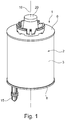
- eine Ansicht auf ein erfindungsgemäßes Filterelement,
- Fig. 2
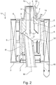
- eine Schnittdarstellung durch eine erfindungsgemäße Filtereinrichtung bei schräg zu einer Achse der Filtereinrichtung eingesetztem Filterelement,
- Fig. 3
- eine Darstellung wie in
Fig. 2 , jedoch bei parallel bzw. identisch verlaufenden Achsen des Filterelements und der Filtereinrichtung. - Entsprechend den
Fig. 1 bis 3 , weist ein erfindungsgemäßes Filterelement 1, welches bspw. als Luftfilter, als Ölfilter oder als Kraftstofffilter eines Fahrzeugs und/oder einer Brennkraftmaschine ausgebildet sein kann, einen ringförmigen Filterkörper 2 aus einem Filtermaterial 3 auf, das einen zylindrischen Innenraum 4 (vgl. insbesondere dieFig. 2 und3 ) umgibt. Ebenfalls vorgesehen ist eine Innenzarge 5, an der sich der Filterkörper 2 radial innen abstützt. Nach oben ist das erfindungsgemäße Filterelement 1 in bekannter Weise über eine obere Endscheibe 6 abgeschlossen, die axial am Filterkörper 2 angeordnet ist und eine zentrale erste Scheibenöffnung 7 aufweist. Nach unten in Axialrichtung des (Ring-)filterelements 1 ist der Filterkörper 2 über eine untere Endscheibe 8 abgeschlossen, die eine zentrale zweite Scheibenöffnung 7' aufweist. Erfindungsgemäß sind nun mehrere in Umfangsrichtung um die erste Scheibenöffnung 7 verteilt angeordnete und axial in den Innenraum 4 abstehende Zentrierelemente 9 vorgesehen, deren, der oberen Endscheibe 6 abgewandte Längsenden abgeschrägt sind und dadurch eine Schräge 10 aufweisen, so dass eine axiale Länge der Zentrierelemente 9 radial innen kleiner ist als radial außen. Diese Zentrierelemente 9 mit ihren Schrägen 10 bewirken ein vereinfachtes Aufstecken des Filterelements 1 auf ein Steigrohr 11, welches bspw. an einem nicht näher bezeichneten Funktionsträger in einem Filtergehäuse 12 einer Filtereinrichtung 13 angeordnet ist. Darüber hinaus vorgesehen ist ein Positioniersteg 14, der an der oberen Endscheibe 6 und/oder an der Innenzarge 5 in Umfangsrichtung zwischen zwei benachbarten Zentrierelementen 9 angeordnet ist und parallel zu diesen verläuft. Über den Positioniersteg 14 ist eine Drehausrichtung eines exzentrisch an der unteren Endscheibe 8 angeordneten und axial abstehenden Pins 15 relativ zu einem filtergehäuseseitigen Leerlaufkanal 16 möglich, so dass bei dem erfindungsgemäßen Filterelement 1 sowohl die Zentrierelemente 9 als auch der Positioniersteg 14 an der oberen Endscheibe 6 bzw. an der Innenzarge 5 angeordnet, insbesondere sogar einstückig mit dieser ausgebildet sind und einen Einbau des Filterelements 1 in das Filtergehäuse 12 der Filtereinrichtung 13, bspw. eines Luftfilters, eines Kraftstofffilters oder eines Ölfilters, erleichtern. Betrachtet man dieFig. 2 und3 , so kann man erkennen, dass der Positioniersteg 14 in Axialrichtung 17 kürzer ausgebildet ist als die Zentrierelemente 9, so dass bei einem Einbau des erfindungsgemäßes Filterelements 1 in die Filtereinrichtung 13 zuerst die Positionierelemente 9 ein paralleles bzw. identisches Ausrichten einer Filterelementachse 18 relativ zu einer Steigrohrachse 19 bewirken. - Betrachtet man das erfindungsgemäße Filterelement 1 weiter, so kann man erkennen, dass an der oberen Endscheibe 6 ein axial abstehender Stutzen 20 angeordnet ist, wobei sich zumindest die Zentrierelemente 9 bis in den Stutzen 20 erstrecken. Ebenso kann sich auch der Positioniersteg 14 in den Stutzen 20 erstrecken.
- Wie der
Fig. 3 zu entnehmen ist, weist die erfindungsgemäße Filtereinrichtung 13 das zuvor beschriebene Filtergehäuse 12 mit dem darin angeordneten Steigrohr 11 auf, das an einem der oberen Endscheibe 6 zugewandten freien Längsende eine Positionierkontur 21 in Form einer Schräge aufweist. Dabei ist selbstverständlich klar, dass die Positionierkontur 21 nicht in der Art einer kanülenartigen Schräge ausgebildet sein muss, sondern auch einen Schraubengang bilden kann. An einer tiefsten Stelle der Positionierkontur 21 ist dabei eine Axialnut 22 zur Aufnahme des Positionierstegs 14 angeordnet. - Ein Innendurchmesser der Zentrierelemente 9 entspricht dabei einem Außendurchmesser des Steigrohrs 11 oder ist geringfügig größer als ein Außendurchmesser des Steigrohrs 11, wodurch eine Führung des Filterelements 1 durch seine Zentrierelemente 9 am Steigrohr 11 erfolgen kann. Insgesamt sind dabei zumindest drei, vier, vorzugsweise sogar sechs oder mehr, Zentrierelemente 9 vorgesehen.
- Um die erfindungsgemäße Wirkung des erfindungsgemäßen Filterelements 1 näher erläutern zu können, wird nachfolgend auf den Montagevorgang des Filterelements 1 in der Filtereinrichtung 13 näher eingegangen.
- Zur Montage des Filterelements 1 in dem Filtergehäuse 12 der Filtereinrichtung 13 wird dieses zunächst von oben eingesetzt, wobei bei einer zunächst auftretenden Schrägstellung der Filterelementachse 18 zur Steigrohrachse 19 keine Schwierigkeiten wie bislang auftreten, da das Steigrohr 11 mit seiner Positionierkontur 21, insbesondere mit seiner oberen Spitze der Positionierkontur 21 zunächst über die Schrägen 10 der Zentrierelemente 9 oder zumindest an einer Schräge 10 zumindest eines Zentrierelements 9 entlang fährt und dadurch das Filterelement 1 relativ zum Steigrohr 11 ausrichtet. Sobald der Positioniersteg 14 des Filterelements 1 mit der Positionierkontur 21 des Steigrohrs 11 in Kontakt tritt, erfolgt ein Verdrehen und gleichzeitig ein axiales Verstellen des Filterelements 1 im Filtergehäuse 12. Erreicht der Positioniersteg 14 die steigrohrseitige Axialnut 22, ist der Pin 15 fluchtend zum filtergehäuseseitigen Leerlaufkanal 16 ausgerichtet und es erfolgt keine Verdrehung des Filterelements 1 mehr, sondern lediglich ein axiales Verschieben des Filterelements 1 im Filtergehäuse 12 der Filtereinrichtung 13, bei welchem der Pin 15 in den Leerlaufkanal 16 eingeschoben wird und diesen verschließt. Mit den erfindungsgemäßen Zentrierelementen 9 kann somit insbesondere ein Verkanten des Filterelements 1 relativ zum Steigrohr 11 vermieden werden, wodurch sich insbesondere die Gefahr einer Beschädigung, bspw. durch Abbrechen von Teilen, am Filterelement 1 und/oder am Steigrohr 11 verhindern lassen. Die Zentrierelemente 9 mit ihren Schrägen 10 ermöglichen dabei ein vergleichsweise einfaches Zentrieren und Ausrichten des Filterelements 1 relativ zum Filtergehäuse 12 und zugleich eine Führung des Filterelements 1, da ein Innendurchmesser der Zentrierelemente 9 im Wesentlichen einem Außendurchmesser des Steigrohrs 11 entspricht.
- Durch die einstückige Ausbildung der oberen Endscheibe 6 und/oder der Innenzarge 5 zusammen mit den Zentrierelementen 9 und/oder dem Positioniersteg 14, insbesondere als einstückiges Kunststoffspritzgussteil, kann auch eine kostengünstige Herstellung ermöglicht werden.
- Aus den
Fig. 2 und3 ist zudem zu erkennen, dass sich der Positioniersteg 14 radial weiter nach innen erstreckt als die Zentrierelemente 9, so dass es bei einer Montage des Filterelements 1 im Filtergehäuse 12 der Filtereinrichtung 13 möglich ist, die Zentrierelemente 9 des Filterelements 1 auf einer äußeren Mantelfläche des Steigrohrs 11 zu führen, während der Positioniersteg 14 mit der Positionierkontur 21 zusammenwirkt und in die Axialnut 22 der Positionierkontur 21 eingreifen kann, was den Zentrierelementen 9 nicht möglich ist.
Claims (10)
- Filterelement (1), insbesondere ein Luftfilter, ein Ölfilter oder ein Kraftstofffilter eines Fahrzeugs und/oder einer Brennkraftmaschine,- mit einem ringförmigen Filterkörper (2) aus einem Filtermaterial (3), das einen zylindrischen Innenraum (4) umgibt,- mit einer Innenzarge (5), an der sich der Filterkörper (2) radial innen abstützt,- mit einer oberen Endscheibe (6), die axial am Filterkörper (2) angeordnet ist und eine zentrale erste Scheibenöffnung (7) aufweist,- mit einer unteren Endscheibe (8), die axial am Filterkörper (2) angeordnet ist und eine zentrale zweite Scheibenöffnung (7') aufweist und an welcher ein exzentrisch angeordneter und axial abstehender Pin (15) zum Verschließen eines Leerlaufkanals (16) angeordnet ist,dadurch gekennzeichnet,- dass mehrere in Umfangsrichtung um die erste Scheibenöffnung (7) verteilt angeordnete und axial in den Innenraum (4) abstehende Zentrierelemente (9) vorgesehen sind, die jeweils eine Schräge (10) aufweisen, wobei eine axiale Länge der Zentrierelemente (9) radial innen kleiner ist als radial außen,- dass ein Positioniersteg (14) vorgesehen ist, der an der oberen Endscheibe (6) und/oder an der Innenzarge (5) in Umfangsrichtung zwischen zwei Zentrierelementen (9) angeordnet ist und der parallel zu diesen verläuft.
- Filterelement nach Anspruch 1,
dadurch gekennzeichnet,
dass der Positioniersteg (14) in Axialrichtung (17) kürzer ausgebildet ist, als die Zentrierelemente (9). - Filterelement nach Anspruch 1 oder 2,
dadurch gekennzeichnet,
dass die Endscheibe (6) und/oder die Innenzarge (5) einstückig mit den Zentrierelementen (9) und/oder dem Positioniersteg (14), insbesondere als einstückiges Kunststoffspritzgussteil, ausgebildet sind. - Filterelement nach einem der vorhergehenden Ansprüche,
dadurch gekennzeichnet,
dass das Zentrierelement (9) und/oder der Positioniersteg (14) als separate Bauteile ausgebildet sind, welche mit der Endscheibe (6) und/oder der Innenzarge (5) verbunden sind. - Filterelement nach einem der Ansprüche 1 bis 4,
dadurch gekennzeichnet,
dass zumindest drei, vorzugsweise vier, sechs oder mehr, Zentrierelemente (9) vorgesehen sind. - Filterelement nach einem der Ansprüche 1 bis 5,
dadurch gekennzeichnet,
dass an der oberen Endscheibe (6) ein axial abstehender Stutzen (20) angeordnet ist, wobei sich zumindest die Zentrierelemente (9) in den Stutzen (20) erstrecken. - Filterelement nach Anspruch 6,
dadurch gekennzeichnet,
dass sich der Positioniersteg (14) in den Stutzen (20) erstreckt. - Filterelement nach einem der Ansprüche 1 bis 7,
dadurch gekennzeichnet,
dass sich der Positioniersteg (14) radial weiter nach innen erstreckt als die Zentrierelemente (9). - Filtereinrichtung (13), insbesondere ein Luftfilter, ein Ölfilter oder ein Kraftstofffilter eines Kraftfahrzeugs und/oder einer Brennkraftmaschine,- mit einem Filterelement (1) nach einem der Ansprüche 1 bis 8,- mit einem Filtergehäuse (12) und einem darin angeordneten Steigrohr (11), das an einem oberen Längsende eine Positionierkontur (21), insbesondere in Form einer Schräge, aufweist, die mit dem Positioniersteg (14) des Filterelements (1) zusammenwirkt,- wobei ein Innendurchmesser der Zentrierelemente (9) im Wesentlichen einem Außendurchmesser des Steigrohrs (11) entspricht.
- Filtereinrichtung nach Anspruch 9,
dadurch gekennzeichnet,
dass an einer tiefsten Stelle der Positionierkontur (11) eine Axialnut (22) zur Aufnahme des Positioniersteges (14) angeordnet ist.
Applications Claiming Priority (1)
| Application Number | Priority Date | Filing Date | Title |
|---|---|---|---|
| DE102017222526.2A DE102017222526A1 (de) | 2017-12-12 | 2017-12-12 | Filterelement und zugehörige Filtereinrichtung |
Publications (2)
| Publication Number | Publication Date |
|---|---|
| EP3498359A1 true EP3498359A1 (de) | 2019-06-19 |
| EP3498359B1 EP3498359B1 (de) | 2021-02-24 |
Family
ID=64316417
Family Applications (1)
| Application Number | Title | Priority Date | Filing Date |
|---|---|---|---|
| EP18206276.0A Active EP3498359B1 (de) | 2017-12-12 | 2018-11-14 | Filterelement und zugehörige filtereinrichtung |
Country Status (3)
| Country | Link |
|---|---|
| US (1) | US10669975B2 (de) |
| EP (1) | EP3498359B1 (de) |
| DE (1) | DE102017222526A1 (de) |
Cited By (1)
| Publication number | Priority date | Publication date | Assignee | Title |
|---|---|---|---|---|
| EP3666357A1 (de) * | 2018-12-14 | 2020-06-17 | Mahle International GmbH | Filtereinrichtung |
Families Citing this family (3)
| Publication number | Priority date | Publication date | Assignee | Title |
|---|---|---|---|---|
| USD967330S1 (en) * | 2019-03-21 | 2022-10-18 | Mahle International Gmbh | Pin for a filter element |
| USD964507S1 (en) | 2019-11-13 | 2022-09-20 | Mahle International Gmbh | Filter |
| CN117090719A (zh) * | 2023-04-17 | 2023-11-21 | 浙江莱恩过滤系统有限公司 | 一种过滤连接件、过滤组件及滤清器 |
Citations (4)
| Publication number | Priority date | Publication date | Assignee | Title |
|---|---|---|---|---|
| US20090090668A1 (en) * | 2007-10-09 | 2009-04-09 | Cummins Filtration Ip, Inc. | Fuel filter assembly with flow restriction valve |
| DE202011104691U1 (de) * | 2011-08-18 | 2012-01-16 | Mahle International Gmbh | Flüssigkeitsfilter, insbesondere ein Ölfilter |
| DE102013209662A1 (de) * | 2013-05-24 | 2014-11-27 | Mahle International Gmbh | Filtereinrichtung |
| DE102015222359A1 (de) * | 2015-11-12 | 2017-05-18 | Mahle International Gmbh | Baukastensystem für ein Ringfilterelement |
Family Cites Families (9)
| Publication number | Priority date | Publication date | Assignee | Title |
|---|---|---|---|---|
| DE69413174T2 (de) * | 1993-10-01 | 1999-05-12 | Honda Giken Kogyo K.K., Tokio/Tokyo | Filter mit Deckel, der nicht drehbar mit dem Filtergehäuse verbunden ist |
| JP3802682B2 (ja) * | 1998-06-17 | 2006-07-26 | 株式会社ニフコ | 燃料用フィルタ |
| DE10118050B4 (de) * | 2001-04-11 | 2004-11-18 | Siemens Ag | Feinfilter für eine Kraftstofffördereinheit |
| DE202005003047U1 (de) | 2005-02-24 | 2006-07-06 | Hengst Gmbh & Co.Kg | Füssigkeitsfilter |
| JP4726749B2 (ja) * | 2006-09-13 | 2011-07-20 | 株式会社Roki | オイルフィルタ |
| DE102006051406A1 (de) * | 2006-10-27 | 2008-04-30 | Mann + Hummel Gmbh | Kraftstofffilter |
| US9011683B2 (en) | 2008-11-14 | 2015-04-21 | Cummins Filtration Ip Inc. | Filter cartridge centering device |
| DE102010009268A1 (de) | 2010-02-25 | 2011-08-25 | MAHLE International GmbH, 70376 | Filterelement und Filtereinrichtung |
| WO2016035203A1 (ja) * | 2014-09-05 | 2016-03-10 | 東京濾器株式会社 | ミスト状オイルの分離方法、及び、オイルセパレータ |
-
2017
- 2017-12-12 DE DE102017222526.2A patent/DE102017222526A1/de not_active Withdrawn
-
2018
- 2018-11-14 EP EP18206276.0A patent/EP3498359B1/de active Active
- 2018-12-11 US US16/216,996 patent/US10669975B2/en active Active
Patent Citations (4)
| Publication number | Priority date | Publication date | Assignee | Title |
|---|---|---|---|---|
| US20090090668A1 (en) * | 2007-10-09 | 2009-04-09 | Cummins Filtration Ip, Inc. | Fuel filter assembly with flow restriction valve |
| DE202011104691U1 (de) * | 2011-08-18 | 2012-01-16 | Mahle International Gmbh | Flüssigkeitsfilter, insbesondere ein Ölfilter |
| DE102013209662A1 (de) * | 2013-05-24 | 2014-11-27 | Mahle International Gmbh | Filtereinrichtung |
| DE102015222359A1 (de) * | 2015-11-12 | 2017-05-18 | Mahle International Gmbh | Baukastensystem für ein Ringfilterelement |
Cited By (2)
| Publication number | Priority date | Publication date | Assignee | Title |
|---|---|---|---|---|
| EP3666357A1 (de) * | 2018-12-14 | 2020-06-17 | Mahle International GmbH | Filtereinrichtung |
| US11285409B2 (en) | 2018-12-14 | 2022-03-29 | Mahle International Gmbh | Filter device |
Also Published As
| Publication number | Publication date |
|---|---|
| DE102017222526A1 (de) | 2019-06-13 |
| US20190203674A1 (en) | 2019-07-04 |
| US10669975B2 (en) | 2020-06-02 |
| EP3498359B1 (de) | 2021-02-24 |
Similar Documents
| Publication | Publication Date | Title |
|---|---|---|
| EP3345670B1 (de) | Filtereinrichtung | |
| EP2490786B1 (de) | Filtereinrichtung | |
| DE102009041523B4 (de) | Filtereinrichtung | |
| EP3498359B1 (de) | Filterelement und zugehörige filtereinrichtung | |
| EP3458175B1 (de) | Filtereinrichtung | |
| EP2553224B1 (de) | Kupplungseinrichtung, kurbelgehäuseentlüftungseinrichtung und frischluftanlage | |
| EP2314364B1 (de) | Filtereinrichtung | |
| EP2407698A2 (de) | Kupplungseinrichtung, Kurbelgehäuseentlüfungseinrichtung und Frischluftanlage | |
| EP2598746B1 (de) | Startvorrichtung für eine brennkraftmaschine | |
| EP3535039B1 (de) | Filtereinrichtung | |
| DE102004016051B4 (de) | Bremskraftverstärker | |
| EP3669960B1 (de) | Filtereinrichtung | |
| EP3120914A1 (de) | Filtereinrichtung | |
| EP3666357B1 (de) | Filtereinrichtung, funktionsträger und verwendung eines ringfilterelements | |
| EP2783738B1 (de) | Filtereinrichtung | |
| EP2803399B1 (de) | Flüssigkeitsfilter | |
| DE102021202107B4 (de) | Turboladereinrichtung und Verfahren zur Montage derselben | |
| DE102015214065A1 (de) | Filtereinrichtung | |
| DE102005023327B4 (de) | Rückschlagventil mit Ventilhalter | |
| EP3463612A1 (de) | Filtereinrichtung | |
| DE102018208836A1 (de) | Kraftstofffiltereinrichtung |
Legal Events
| Date | Code | Title | Description |
|---|---|---|---|
| PUAI | Public reference made under article 153(3) epc to a published international application that has entered the european phase |
Free format text: ORIGINAL CODE: 0009012 |
|
| STAA | Information on the status of an ep patent application or granted ep patent |
Free format text: STATUS: THE APPLICATION HAS BEEN PUBLISHED |
|
| AK | Designated contracting states |
Kind code of ref document: A1 Designated state(s): AL AT BE BG CH CY CZ DE DK EE ES FI FR GB GR HR HU IE IS IT LI LT LU LV MC MK MT NL NO PL PT RO RS SE SI SK SM TR |
|
| AX | Request for extension of the european patent |
Extension state: BA ME |
|
| STAA | Information on the status of an ep patent application or granted ep patent |
Free format text: STATUS: REQUEST FOR EXAMINATION WAS MADE |
|
| 17P | Request for examination filed |
Effective date: 20191217 |
|
| RBV | Designated contracting states (corrected) |
Designated state(s): AL AT BE BG CH CY CZ DE DK EE ES FI FR GB GR HR HU IE IS IT LI LT LU LV MC MK MT NL NO PL PT RO RS SE SI SK SM TR |
|
| STAA | Information on the status of an ep patent application or granted ep patent |
Free format text: STATUS: EXAMINATION IS IN PROGRESS |
|
| 17Q | First examination report despatched |
Effective date: 20200602 |
|
| GRAP | Despatch of communication of intention to grant a patent |
Free format text: ORIGINAL CODE: EPIDOSNIGR1 |
|
| STAA | Information on the status of an ep patent application or granted ep patent |
Free format text: STATUS: GRANT OF PATENT IS INTENDED |
|
| INTG | Intention to grant announced |
Effective date: 20200930 |
|
| GRAS | Grant fee paid |
Free format text: ORIGINAL CODE: EPIDOSNIGR3 |
|
| GRAA | (expected) grant |
Free format text: ORIGINAL CODE: 0009210 |
|
| STAA | Information on the status of an ep patent application or granted ep patent |
Free format text: STATUS: THE PATENT HAS BEEN GRANTED |
|
| AK | Designated contracting states |
Kind code of ref document: B1 Designated state(s): AL AT BE BG CH CY CZ DE DK EE ES FI FR GB GR HR HU IE IS IT LI LT LU LV MC MK MT NL NO PL PT RO RS SE SI SK SM TR |
|
| REG | Reference to a national code |
Ref country code: CH Ref legal event code: EP |
|
| REG | Reference to a national code |
Ref country code: AT Ref legal event code: REF Ref document number: 1363738 Country of ref document: AT Kind code of ref document: T Effective date: 20210315 |
|
| REG | Reference to a national code |
Ref country code: IE Ref legal event code: FG4D Free format text: LANGUAGE OF EP DOCUMENT: GERMAN |
|
| REG | Reference to a national code |
Ref country code: DE Ref legal event code: R096 Ref document number: 502018004000 Country of ref document: DE |
|
| REG | Reference to a national code |
Ref country code: LT Ref legal event code: MG9D |
|
| REG | Reference to a national code |
Ref country code: NL Ref legal event code: MP Effective date: 20210224 |
|
| PG25 | Lapsed in a contracting state [announced via postgrant information from national office to epo] |
Ref country code: LT Free format text: LAPSE BECAUSE OF FAILURE TO SUBMIT A TRANSLATION OF THE DESCRIPTION OR TO PAY THE FEE WITHIN THE PRESCRIBED TIME-LIMIT Effective date: 20210224 Ref country code: PT Free format text: LAPSE BECAUSE OF FAILURE TO SUBMIT A TRANSLATION OF THE DESCRIPTION OR TO PAY THE FEE WITHIN THE PRESCRIBED TIME-LIMIT Effective date: 20210624 Ref country code: NO Free format text: LAPSE BECAUSE OF FAILURE TO SUBMIT A TRANSLATION OF THE DESCRIPTION OR TO PAY THE FEE WITHIN THE PRESCRIBED TIME-LIMIT Effective date: 20210524 Ref country code: FI Free format text: LAPSE BECAUSE OF FAILURE TO SUBMIT A TRANSLATION OF THE DESCRIPTION OR TO PAY THE FEE WITHIN THE PRESCRIBED TIME-LIMIT Effective date: 20210224 Ref country code: HR Free format text: LAPSE BECAUSE OF FAILURE TO SUBMIT A TRANSLATION OF THE DESCRIPTION OR TO PAY THE FEE WITHIN THE PRESCRIBED TIME-LIMIT Effective date: 20210224 Ref country code: GR Free format text: LAPSE BECAUSE OF FAILURE TO SUBMIT A TRANSLATION OF THE DESCRIPTION OR TO PAY THE FEE WITHIN THE PRESCRIBED TIME-LIMIT Effective date: 20210525 Ref country code: BG Free format text: LAPSE BECAUSE OF FAILURE TO SUBMIT A TRANSLATION OF THE DESCRIPTION OR TO PAY THE FEE WITHIN THE PRESCRIBED TIME-LIMIT Effective date: 20210524 |
|
| PG25 | Lapsed in a contracting state [announced via postgrant information from national office to epo] |
Ref country code: PL Free format text: LAPSE BECAUSE OF FAILURE TO SUBMIT A TRANSLATION OF THE DESCRIPTION OR TO PAY THE FEE WITHIN THE PRESCRIBED TIME-LIMIT Effective date: 20210224 Ref country code: NL Free format text: LAPSE BECAUSE OF FAILURE TO SUBMIT A TRANSLATION OF THE DESCRIPTION OR TO PAY THE FEE WITHIN THE PRESCRIBED TIME-LIMIT Effective date: 20210224 Ref country code: LV Free format text: LAPSE BECAUSE OF FAILURE TO SUBMIT A TRANSLATION OF THE DESCRIPTION OR TO PAY THE FEE WITHIN THE PRESCRIBED TIME-LIMIT Effective date: 20210224 Ref country code: RS Free format text: LAPSE BECAUSE OF FAILURE TO SUBMIT A TRANSLATION OF THE DESCRIPTION OR TO PAY THE FEE WITHIN THE PRESCRIBED TIME-LIMIT Effective date: 20210224 Ref country code: SE Free format text: LAPSE BECAUSE OF FAILURE TO SUBMIT A TRANSLATION OF THE DESCRIPTION OR TO PAY THE FEE WITHIN THE PRESCRIBED TIME-LIMIT Effective date: 20210224 |
|
| PG25 | Lapsed in a contracting state [announced via postgrant information from national office to epo] |
Ref country code: IS Free format text: LAPSE BECAUSE OF FAILURE TO SUBMIT A TRANSLATION OF THE DESCRIPTION OR TO PAY THE FEE WITHIN THE PRESCRIBED TIME-LIMIT Effective date: 20210624 |
|
| PG25 | Lapsed in a contracting state [announced via postgrant information from national office to epo] |
Ref country code: SM Free format text: LAPSE BECAUSE OF FAILURE TO SUBMIT A TRANSLATION OF THE DESCRIPTION OR TO PAY THE FEE WITHIN THE PRESCRIBED TIME-LIMIT Effective date: 20210224 Ref country code: EE Free format text: LAPSE BECAUSE OF FAILURE TO SUBMIT A TRANSLATION OF THE DESCRIPTION OR TO PAY THE FEE WITHIN THE PRESCRIBED TIME-LIMIT Effective date: 20210224 Ref country code: CZ Free format text: LAPSE BECAUSE OF FAILURE TO SUBMIT A TRANSLATION OF THE DESCRIPTION OR TO PAY THE FEE WITHIN THE PRESCRIBED TIME-LIMIT Effective date: 20210224 |
|
| REG | Reference to a national code |
Ref country code: DE Ref legal event code: R097 Ref document number: 502018004000 Country of ref document: DE |
|
| PG25 | Lapsed in a contracting state [announced via postgrant information from national office to epo] |
Ref country code: RO Free format text: LAPSE BECAUSE OF FAILURE TO SUBMIT A TRANSLATION OF THE DESCRIPTION OR TO PAY THE FEE WITHIN THE PRESCRIBED TIME-LIMIT Effective date: 20210224 Ref country code: SK Free format text: LAPSE BECAUSE OF FAILURE TO SUBMIT A TRANSLATION OF THE DESCRIPTION OR TO PAY THE FEE WITHIN THE PRESCRIBED TIME-LIMIT Effective date: 20210224 Ref country code: DK Free format text: LAPSE BECAUSE OF FAILURE TO SUBMIT A TRANSLATION OF THE DESCRIPTION OR TO PAY THE FEE WITHIN THE PRESCRIBED TIME-LIMIT Effective date: 20210224 |
|
| PLBE | No opposition filed within time limit |
Free format text: ORIGINAL CODE: 0009261 |
|
| STAA | Information on the status of an ep patent application or granted ep patent |
Free format text: STATUS: NO OPPOSITION FILED WITHIN TIME LIMIT |
|
| PG25 | Lapsed in a contracting state [announced via postgrant information from national office to epo] |
Ref country code: ES Free format text: LAPSE BECAUSE OF FAILURE TO SUBMIT A TRANSLATION OF THE DESCRIPTION OR TO PAY THE FEE WITHIN THE PRESCRIBED TIME-LIMIT Effective date: 20210224 Ref country code: AL Free format text: LAPSE BECAUSE OF FAILURE TO SUBMIT A TRANSLATION OF THE DESCRIPTION OR TO PAY THE FEE WITHIN THE PRESCRIBED TIME-LIMIT Effective date: 20210224 |
|
| 26N | No opposition filed |
Effective date: 20211125 |
|
| PG25 | Lapsed in a contracting state [announced via postgrant information from national office to epo] |
Ref country code: SI Free format text: LAPSE BECAUSE OF FAILURE TO SUBMIT A TRANSLATION OF THE DESCRIPTION OR TO PAY THE FEE WITHIN THE PRESCRIBED TIME-LIMIT Effective date: 20210224 |
|
| PG25 | Lapsed in a contracting state [announced via postgrant information from national office to epo] |
Ref country code: IT Free format text: LAPSE BECAUSE OF FAILURE TO SUBMIT A TRANSLATION OF THE DESCRIPTION OR TO PAY THE FEE WITHIN THE PRESCRIBED TIME-LIMIT Effective date: 20210224 |
|
| PG25 | Lapsed in a contracting state [announced via postgrant information from national office to epo] |
Ref country code: IS Free format text: LAPSE BECAUSE OF FAILURE TO SUBMIT A TRANSLATION OF THE DESCRIPTION OR TO PAY THE FEE WITHIN THE PRESCRIBED TIME-LIMIT Effective date: 20210624 |
|
| PG25 | Lapsed in a contracting state [announced via postgrant information from national office to epo] |
Ref country code: MC Free format text: LAPSE BECAUSE OF FAILURE TO SUBMIT A TRANSLATION OF THE DESCRIPTION OR TO PAY THE FEE WITHIN THE PRESCRIBED TIME-LIMIT Effective date: 20210224 |
|
| REG | Reference to a national code |
Ref country code: CH Ref legal event code: PL |
|
| PG25 | Lapsed in a contracting state [announced via postgrant information from national office to epo] |
Ref country code: LU Free format text: LAPSE BECAUSE OF NON-PAYMENT OF DUE FEES Effective date: 20211114 Ref country code: BE Free format text: LAPSE BECAUSE OF NON-PAYMENT OF DUE FEES Effective date: 20211130 |
|
| REG | Reference to a national code |
Ref country code: BE Ref legal event code: MM Effective date: 20211130 |
|
| PG25 | Lapsed in a contracting state [announced via postgrant information from national office to epo] |
Ref country code: IE Free format text: LAPSE BECAUSE OF NON-PAYMENT OF DUE FEES Effective date: 20211114 |
|
| PG25 | Lapsed in a contracting state [announced via postgrant information from national office to epo] |
Ref country code: CY Free format text: LAPSE BECAUSE OF FAILURE TO SUBMIT A TRANSLATION OF THE DESCRIPTION OR TO PAY THE FEE WITHIN THE PRESCRIBED TIME-LIMIT Effective date: 20210224 |
|
| GBPC | Gb: european patent ceased through non-payment of renewal fee |
Effective date: 20221114 |
|
| PG25 | Lapsed in a contracting state [announced via postgrant information from national office to epo] |
Ref country code: LI Free format text: LAPSE BECAUSE OF NON-PAYMENT OF DUE FEES Effective date: 20220630 Ref country code: HU Free format text: LAPSE BECAUSE OF FAILURE TO SUBMIT A TRANSLATION OF THE DESCRIPTION OR TO PAY THE FEE WITHIN THE PRESCRIBED TIME-LIMIT; INVALID AB INITIO Effective date: 20181114 Ref country code: CH Free format text: LAPSE BECAUSE OF NON-PAYMENT OF DUE FEES Effective date: 20220630 |
|
| PG25 | Lapsed in a contracting state [announced via postgrant information from national office to epo] |
Ref country code: GB Free format text: LAPSE BECAUSE OF NON-PAYMENT OF DUE FEES Effective date: 20221114 |
|
| PG25 | Lapsed in a contracting state [announced via postgrant information from national office to epo] |
Ref country code: MK Free format text: LAPSE BECAUSE OF FAILURE TO SUBMIT A TRANSLATION OF THE DESCRIPTION OR TO PAY THE FEE WITHIN THE PRESCRIBED TIME-LIMIT Effective date: 20210224 |
|
| P01 | Opt-out of the competence of the unified patent court (upc) registered |
Effective date: 20240527 |
|
| PG25 | Lapsed in a contracting state [announced via postgrant information from national office to epo] |
Ref country code: MT Free format text: LAPSE BECAUSE OF FAILURE TO SUBMIT A TRANSLATION OF THE DESCRIPTION OR TO PAY THE FEE WITHIN THE PRESCRIBED TIME-LIMIT Effective date: 20210224 |
|
| REG | Reference to a national code |
Ref country code: AT Ref legal event code: MM01 Ref document number: 1363738 Country of ref document: AT Kind code of ref document: T Effective date: 20231114 |
|
| PG25 | Lapsed in a contracting state [announced via postgrant information from national office to epo] |
Ref country code: AT Free format text: LAPSE BECAUSE OF NON-PAYMENT OF DUE FEES Effective date: 20231114 |
|
| PG25 | Lapsed in a contracting state [announced via postgrant information from national office to epo] |
Ref country code: AT Free format text: LAPSE BECAUSE OF NON-PAYMENT OF DUE FEES Effective date: 20231114 |
|
| PG25 | Lapsed in a contracting state [announced via postgrant information from national office to epo] |
Ref country code: TR Free format text: LAPSE BECAUSE OF FAILURE TO SUBMIT A TRANSLATION OF THE DESCRIPTION OR TO PAY THE FEE WITHIN THE PRESCRIBED TIME-LIMIT Effective date: 20210224 |
|
| PGFP | Annual fee paid to national office [announced via postgrant information from national office to epo] |
Ref country code: DE Payment date: 20251119 Year of fee payment: 8 |
|
| PGFP | Annual fee paid to national office [announced via postgrant information from national office to epo] |
Ref country code: FR Payment date: 20251126 Year of fee payment: 8 |
|
| PGFP | Annual fee paid to national office [announced via postgrant information from national office to epo] |
Ref country code: AT Payment date: 20260410 Year of fee payment: 5 |