EP3498251A1 - Connector, connector-attached medicine container, liquid medicine feeding device - Google Patents
Connector, connector-attached medicine container, liquid medicine feeding device Download PDFInfo
- Publication number
- EP3498251A1 EP3498251A1 EP17839548.9A EP17839548A EP3498251A1 EP 3498251 A1 EP3498251 A1 EP 3498251A1 EP 17839548 A EP17839548 A EP 17839548A EP 3498251 A1 EP3498251 A1 EP 3498251A1
- Authority
- EP
- European Patent Office
- Prior art keywords
- inner tube
- end side
- connector
- outer tube
- distal end
- Prior art date
- Legal status (The legal status is an assumption and is not a legal conclusion. Google has not performed a legal analysis and makes no representation as to the accuracy of the status listed.)
- Granted
Links
- 239000003814 drug Substances 0.000 title claims abstract description 170
- 239000007788 liquid Substances 0.000 title claims description 95
- 229940079593 drug Drugs 0.000 claims abstract description 168
- 238000003780 insertion Methods 0.000 claims abstract description 93
- 230000037431 insertion Effects 0.000 claims abstract description 93
- 230000007246 mechanism Effects 0.000 claims abstract description 23
- 239000012530 fluid Substances 0.000 claims abstract description 18
- 230000008878 coupling Effects 0.000 claims description 79
- 238000010168 coupling process Methods 0.000 claims description 79
- 238000005859 coupling reaction Methods 0.000 claims description 79
- 238000012546 transfer Methods 0.000 claims description 47
- 238000004891 communication Methods 0.000 claims description 17
- 230000002093 peripheral effect Effects 0.000 claims description 17
- 208000012266 Needlestick injury Diseases 0.000 claims description 2
- 239000010408 film Substances 0.000 description 38
- 238000001802 infusion Methods 0.000 description 37
- 239000000443 aerosol Substances 0.000 description 13
- 239000011248 coating agent Substances 0.000 description 12
- 238000000576 coating method Methods 0.000 description 12
- 239000000463 material Substances 0.000 description 8
- 229920005989 resin Polymers 0.000 description 7
- 239000011347 resin Substances 0.000 description 7
- 229920001971 elastomer Polymers 0.000 description 4
- 230000001681 protective effect Effects 0.000 description 4
- 239000005060 rubber Substances 0.000 description 4
- 229920002725 thermoplastic elastomer Polymers 0.000 description 4
- 229920005549 butyl rubber Polymers 0.000 description 3
- 238000002360 preparation method Methods 0.000 description 3
- 238000007789 sealing Methods 0.000 description 3
- 244000043261 Hevea brasiliensis Species 0.000 description 2
- 239000002246 antineoplastic agent Substances 0.000 description 2
- 229940041181 antineoplastic drug Drugs 0.000 description 2
- 244000052616 bacterial pathogen Species 0.000 description 2
- 229920005556 chlorobutyl Polymers 0.000 description 2
- 230000000694 effects Effects 0.000 description 2
- 238000007667 floating Methods 0.000 description 2
- 238000001990 intravenous administration Methods 0.000 description 2
- 229920003052 natural elastomer Polymers 0.000 description 2
- 229920001194 natural rubber Polymers 0.000 description 2
- 239000002547 new drug Substances 0.000 description 2
- -1 polytetrafluoroethylene Polymers 0.000 description 2
- 239000005871 repellent Substances 0.000 description 2
- 238000005507 spraying Methods 0.000 description 2
- 241000894006 Bacteria Species 0.000 description 1
- OKTJSMMVPCPJKN-UHFFFAOYSA-N Carbon Chemical compound [C] OKTJSMMVPCPJKN-UHFFFAOYSA-N 0.000 description 1
- 239000005062 Polybutadiene Substances 0.000 description 1
- 239000004793 Polystyrene Substances 0.000 description 1
- XSTXAVWGXDQKEL-UHFFFAOYSA-N Trichloroethylene Chemical group ClC=C(Cl)Cl XSTXAVWGXDQKEL-UHFFFAOYSA-N 0.000 description 1
- 229920000122 acrylonitrile butadiene styrene Polymers 0.000 description 1
- 230000009471 action Effects 0.000 description 1
- 238000013459 approach Methods 0.000 description 1
- 229910052799 carbon Inorganic materials 0.000 description 1
- 231100000507 endocrine disrupting Toxicity 0.000 description 1
- 229920000840 ethylene tetrafluoroethylene copolymer Polymers 0.000 description 1
- 239000000835 fiber Substances 0.000 description 1
- 239000011521 glass Substances 0.000 description 1
- 230000002209 hydrophobic effect Effects 0.000 description 1
- 238000007689 inspection Methods 0.000 description 1
- 229920003049 isoprene rubber Polymers 0.000 description 1
- 230000004048 modification Effects 0.000 description 1
- 238000012986 modification Methods 0.000 description 1
- 239000011295 pitch Substances 0.000 description 1
- 229920002857 polybutadiene Polymers 0.000 description 1
- 229920000515 polycarbonate Polymers 0.000 description 1
- 239000004417 polycarbonate Substances 0.000 description 1
- 229920002223 polystyrene Polymers 0.000 description 1
- 229920001343 polytetrafluoroethylene Polymers 0.000 description 1
- 239000004810 polytetrafluoroethylene Substances 0.000 description 1
- 230000004044 response Effects 0.000 description 1
- 238000005070 sampling Methods 0.000 description 1
- 229920002379 silicone rubber Polymers 0.000 description 1
- 239000004945 silicone rubber Substances 0.000 description 1
- 239000002904 solvent Substances 0.000 description 1
- 230000003068 static effect Effects 0.000 description 1
- 229920003048 styrene butadiene rubber Polymers 0.000 description 1
- 239000000126 substance Substances 0.000 description 1
- 239000010409 thin film Substances 0.000 description 1
- UBOXGVDOUJQMTN-UHFFFAOYSA-N trichloroethylene Natural products ClCC(Cl)Cl UBOXGVDOUJQMTN-UHFFFAOYSA-N 0.000 description 1
Images


Classifications
-
- A—HUMAN NECESSITIES
- A61—MEDICAL OR VETERINARY SCIENCE; HYGIENE
- A61J—CONTAINERS SPECIALLY ADAPTED FOR MEDICAL OR PHARMACEUTICAL PURPOSES; DEVICES OR METHODS SPECIALLY ADAPTED FOR BRINGING PHARMACEUTICAL PRODUCTS INTO PARTICULAR PHYSICAL OR ADMINISTERING FORMS; DEVICES FOR ADMINISTERING FOOD OR MEDICINES ORALLY; BABY COMFORTERS; DEVICES FOR RECEIVING SPITTLE
- A61J1/00—Containers specially adapted for medical or pharmaceutical purposes
- A61J1/14—Details; Accessories therefor
- A61J1/20—Arrangements for transferring or mixing fluids, e.g. from vial to syringe
- A61J1/2089—Containers or vials which are to be joined to each other in order to mix their contents
-
- A—HUMAN NECESSITIES
- A61—MEDICAL OR VETERINARY SCIENCE; HYGIENE
- A61J—CONTAINERS SPECIALLY ADAPTED FOR MEDICAL OR PHARMACEUTICAL PURPOSES; DEVICES OR METHODS SPECIALLY ADAPTED FOR BRINGING PHARMACEUTICAL PRODUCTS INTO PARTICULAR PHYSICAL OR ADMINISTERING FORMS; DEVICES FOR ADMINISTERING FOOD OR MEDICINES ORALLY; BABY COMFORTERS; DEVICES FOR RECEIVING SPITTLE
- A61J1/00—Containers specially adapted for medical or pharmaceutical purposes
- A61J1/14—Details; Accessories therefor
- A61J1/20—Arrangements for transferring or mixing fluids, e.g. from vial to syringe
- A61J1/2096—Combination of a vial and a syringe for transferring or mixing their contents
-
- A—HUMAN NECESSITIES
- A61—MEDICAL OR VETERINARY SCIENCE; HYGIENE
- A61J—CONTAINERS SPECIALLY ADAPTED FOR MEDICAL OR PHARMACEUTICAL PURPOSES; DEVICES OR METHODS SPECIALLY ADAPTED FOR BRINGING PHARMACEUTICAL PRODUCTS INTO PARTICULAR PHYSICAL OR ADMINISTERING FORMS; DEVICES FOR ADMINISTERING FOOD OR MEDICINES ORALLY; BABY COMFORTERS; DEVICES FOR RECEIVING SPITTLE
- A61J1/00—Containers specially adapted for medical or pharmaceutical purposes
- A61J1/14—Details; Accessories therefor
- A61J1/20—Arrangements for transferring or mixing fluids, e.g. from vial to syringe
- A61J1/2003—Accessories used in combination with means for transfer or mixing of fluids, e.g. for activating fluid flow, separating fluids, filtering fluid or venting
- A61J1/2006—Piercing means
- A61J1/201—Piercing means having one piercing end
-
- A—HUMAN NECESSITIES
- A61—MEDICAL OR VETERINARY SCIENCE; HYGIENE
- A61J—CONTAINERS SPECIALLY ADAPTED FOR MEDICAL OR PHARMACEUTICAL PURPOSES; DEVICES OR METHODS SPECIALLY ADAPTED FOR BRINGING PHARMACEUTICAL PRODUCTS INTO PARTICULAR PHYSICAL OR ADMINISTERING FORMS; DEVICES FOR ADMINISTERING FOOD OR MEDICINES ORALLY; BABY COMFORTERS; DEVICES FOR RECEIVING SPITTLE
- A61J1/00—Containers specially adapted for medical or pharmaceutical purposes
- A61J1/14—Details; Accessories therefor
- A61J1/20—Arrangements for transferring or mixing fluids, e.g. from vial to syringe
- A61J1/2003—Accessories used in combination with means for transfer or mixing of fluids, e.g. for activating fluid flow, separating fluids, filtering fluid or venting
- A61J1/2048—Connecting means
- A61J1/2055—Connecting means having gripping means
-
- A—HUMAN NECESSITIES
- A61—MEDICAL OR VETERINARY SCIENCE; HYGIENE
- A61J—CONTAINERS SPECIALLY ADAPTED FOR MEDICAL OR PHARMACEUTICAL PURPOSES; DEVICES OR METHODS SPECIALLY ADAPTED FOR BRINGING PHARMACEUTICAL PRODUCTS INTO PARTICULAR PHYSICAL OR ADMINISTERING FORMS; DEVICES FOR ADMINISTERING FOOD OR MEDICINES ORALLY; BABY COMFORTERS; DEVICES FOR RECEIVING SPITTLE
- A61J1/00—Containers specially adapted for medical or pharmaceutical purposes
- A61J1/14—Details; Accessories therefor
- A61J1/20—Arrangements for transferring or mixing fluids, e.g. from vial to syringe
- A61J1/2003—Accessories used in combination with means for transfer or mixing of fluids, e.g. for activating fluid flow, separating fluids, filtering fluid or venting
- A61J1/2068—Venting means
- A61J1/2075—Venting means for external venting
-
- A—HUMAN NECESSITIES
- A61—MEDICAL OR VETERINARY SCIENCE; HYGIENE
- A61J—CONTAINERS SPECIALLY ADAPTED FOR MEDICAL OR PHARMACEUTICAL PURPOSES; DEVICES OR METHODS SPECIALLY ADAPTED FOR BRINGING PHARMACEUTICAL PRODUCTS INTO PARTICULAR PHYSICAL OR ADMINISTERING FORMS; DEVICES FOR ADMINISTERING FOOD OR MEDICINES ORALLY; BABY COMFORTERS; DEVICES FOR RECEIVING SPITTLE
- A61J1/00—Containers specially adapted for medical or pharmaceutical purposes
- A61J1/14—Details; Accessories therefor
- A61J1/20—Arrangements for transferring or mixing fluids, e.g. from vial to syringe
- A61J1/2003—Accessories used in combination with means for transfer or mixing of fluids, e.g. for activating fluid flow, separating fluids, filtering fluid or venting
- A61J1/2079—Filtering means
- A61J1/2082—Filtering means for gas filtration
Definitions
- the present invention relates to a connector, a connector-attached drug container, and a liquid drug transfer device for use in mixing a drug and a liquid drug to prepare a drug solution.
- a conventional liquid drug transfer device is disclosed in, for example, Japanese National Patent Publication No. 2016-511662 (PTL 1).
- the liquid drug transfer device disclosed in PTL 1 includes a syringe (drug container), a vial with its mouth sealed by an elastic lid, a connecting tool (connector) connected to a distal end of the syringe, and a coupling tool connecting the connecting tool and the vial to each other.
- the coupling tool has a needle having a liquid hole and sticking into the elastic lid.
- the connecting tool includes a tubular portion that is screwed with a screwing portion of the syringe and is axially movable relative to the needle.
- the tubular portion has a hollow passage at one end thereof and a needle insertion attachment portion at the other end thereof.
- the hollow passage is in communication with the interior of the syringe while being screwed with the syringe.
- the needle insertion attachment portion can receive the proximal end side of the needle.
- the liquid hole of the needle is provided so as to be in communication with the hollow passage.
- the needle is stuck into the elastic lid of the vial and is attached to the vial, and subsequently, the syringe is brought closer to the one end side of the tubular portion, thereby screwing the tubular portion with the screwing portion of the syringe.
- the proximal end side of the needle is inserted into the needle insertion attachment portion of the syringe screwed with the tubular portion, and the syringe is pushed toward the vial. This causes the proximal end side of the needle to enter the tubular portion so as to approach the one end of the tubular portion.
- the distal end side of the hollow passage passes through a sealing film provided on the proximal end side of the needle, so that the interior of the syringe and the interior of the vial are in communication with each other through the hollow passage of the tubular portion and the liquid hole of the needle.
- the liquid drug contained in the syringe is transferred into the drug container, and the liquid drug and the drug contained in the vial are mixed together, thus preparing a drug solution.
- the liquid drug transfer device disclosed in PTL 1 has a configuration in which one end side of the tubular portion is screwed with the screwing portion of the syringe to attach the syringe to the connecting tool. Consequently, when the position of the liquid drug transfer device is changed, for example, the syringe and the coupling tool may be unscrewed from each other to cause leakage of the liquid contained in the syringe.
- the present invention has been made in view of the above problem, and has an object to provide a connector, a connector-attached drug container, and a liquid drug transfer device capable of preventing a drug container from becoming detached from a connecting tool.
- a connector according to the present invention includes an outer tube, an inner tube held by the outer tube while being inserted into the outer tube, a fluid channel which has a hollow passage and is fixed to a distal end side of the inner tube and accommodated in the outer tube, and a ratchet mechanism which allows rotation of the inner tube in one direction while restricting rotation of the inner tube in the other direction.
- the inner tube includes an insertion attachment portion which is provided on a proximal end side of the inner tube and with which a distal end side of a drug container is screwed to be attached thereto by insertion.
- the ratchet mechanism restricts rotation of the inner tube together with the drug container in a screwing direction and allows the inner tube to rotate freely relative to the outer tube together with the drug container in an unscrewing direction opposite to the screwing direction.
- the ratchet mechanism preferably includes a ratchet tooth fixed relative to the inner tube and provided to project radially outwardly of the inner tube, and a ratchet pawl provided on a proximal end side of the outer tube and projecting inwardly of the outer tube from an inner peripheral surface of the outer tube.
- the connector according to the present invention further includes a ratchet tooth support supporting the ratchet tooth.
- the ratchet tooth support preferably includes a flange projecting radially outwardly from an outer peripheral surface of the inner tube, and a wall extending in a tube axis direction of the inner tube and having one end side connected to the flange and the other end side serving as a free end.
- the ratchet tooth is preferably provided to project radially outwardly from the wall.
- the connector according to the present invention preferably further includes a valve having a valve hole which is provided so as to open and close and closes a distal end side of the outer tube.
- a connector-attached drug container includes a connector and a drug container.
- the connector includes an outer tube, an inner tube held by the outer tube while being inserted into the outer tube, a fluid channel which has a hollow passage and is fixed to a distal end side of the inner tube and accommodated in the outer tube, and a ratchet mechanism which allows rotation of the inner tube in one direction while restricting rotation of the inner tube in the other direction.
- the drug container includes a tubular container and a plunger inserted from a proximal end side of the tubular container.
- the tubular container has a nozzle provided on a distal end side of the tubular container and a surrounding portion surrounding at least a proximal end side of the nozzle, and contains a liquid drug.
- the inner tube includes an insertion attachment portion which is provided on a proximal end side of the inner tube and with which a distal end side of the drug container is screwed to be attached thereto by insertion.
- the surrounding portion has a screwing portion screwed with the insertion attachment portion of the connector.
- the ratchet mechanism restricts rotation of the inner tube together with the drug container in a screwing direction and allows the inner tube to rotate freely relative to the outer tube together with the drug container in an unscrewing direction opposite to the screwing direction.
- the screwing portion is screwed with the insertion attachment portion to connect the connector to the distal end side of the drug container.
- a liquid drug transfer device includes a connector, a first coupling tool, and a drug container.
- the connector includes an outer tube, an inner tube held by the outer tube while being inserted into the outer tube, a fluid channel which has a hollow passage and is fixed to a distal end side of the inner tube and accommodated in the outer tube, and a ratchet mechanism which allows rotation of the inner tube in one direction while restricting rotation of the inner tube in the other direction.
- the first coupling tool has a mouth. The mouth is tightly closed by an elastic stopper body.
- the first coupling tool couples a vial containing a drug and the connector to each other.
- the drug container includes a tubular container and a plunger inserted from a proximal end side of the tubular container.
- the tubular container has a nozzle provided on a distal end side of the tubular container and a surrounding portion surrounding at least a proximal end side of the nozzle, and contains a liquid drug.
- the inner tube includes an insertion attachment portion which is provided on a proximal end side of the inner tube and with which the distal end side of drug container is screwed to be attached thereto by insertion.
- the surrounding portion has a screwing portion screwed with the insertion attachment portion of the connector.
- the ratchet mechanism restricts rotation of the inner tube together with the drug container in a screwing direction and allows the inner tube to rotate freely together with the drug container relative to the outer tube in an unscrewing direction opposite to the screwing direction.
- the first coupling tool includes a tubular portion which is inserted into a distal end side of the outer tube of the connector to cause a distal end side of the fluid channel to be inserted thereinto, and a puncture needle which has a liquid hole being in communication with an interior of the tubular portion and is provided so as to stick into an elastic stopper body of the vial.
- the screwing portion is screwed with the insertion attachment portion to connect the connector to the distal end side of the drug container and in a state in which the puncture needle sticks into the elastic stopper body of the vial to insert the distal end side of the fluid channel into the tubular portion, an interior of the vial, the liquid hole, an interior of the tubular portion, the hollow passage of the fluid channel, an interior of the inner tube, and an interior of the nozzle are in communication with each other to allow transfer of the liquid drug contained in the drug container into the vial.
- the present invention can provide a connector, a connector-attached drug container, and a liquid drug transfer device capable of preventing a drug container from becoming detached from a connecting tool.
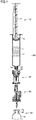
- Fig. 1 is a sectional view of components of a liquid drug transfer device and a vial according to Embodiment 1. With reference to Fig. 1 , the liquid drug transfer device according to Embodiment 1 will be described.
- a liquid drug transfer device 100 connects a syringe 10 serving as a drug container, a connector 20 serving as a connecting tool, a first coupling tool 30 serving as a first coupling tool, and a vial 40 to each other to cause the interior of syringe 10 and the interior of vial 40 to be in communication with each other, allows a liquid drug L contained in syringe 10 to be transferred into vial 40, and mixes a drug (not shown) contained in vial 40 and liquid drug L in vial 40, thereby preparing a drug solution.
- liquid drug transfer device 100 includes syringe 10, connector 20, and first coupling tool 30.
- Syringe 10 includes a tubular container 11 which is open at its opposite ends, and a plunger 17.
- Tubular container 11 contains liquid drug L.
- Liquid drug L is an object to be contained which forms a drug.
- Tubular container 11 has a nozzle 12 provided on its distal end side and a surrounding portion 13 surrounding nozzle 12.
- a screwing portion 14 having a spiral shape is provided on the inner peripheral surface of surrounding portion 13.
- Plunger 17 is inserted into tubular container 11 from the proximal end side of tubular container 11.
- a gasket 16 is provided on the distal end side of plunger 17.
- Gasket 16 is provided to be freely slidable within tubular container 11 and keeps the inner peripheral surface of tubular container 11 and gasket 16 liquid tight.
- Liquid drug L is contained in the space defined by tubular container 11 and gasket 16.
- Gasket 16 may be, for example, natural rubber, butyl rubber, chlorinated butyl rubber, ethylene-butadiene rubber, or thermoplastic elastomer.
- Vial 40 contains a drug (not shown).
- Vial 40 includes a container body 41 having a mouth 42, and an elastic stopper body 43 sealing mouth 42.
- Container body 41 may be, for example, a glass container or a resin container.
- Elastic stopper body 43 may be, for example, a rubber member or a thermoplastic elastomer resin.
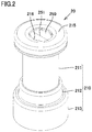
- Fig. 2 is a perspective view of the connector according to Embodiment 1.
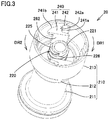
- Fig. 3 is a perspective view showing the interior on the proximal end side of the connector according to Embodiment 1.
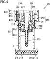
- Fig. 4 is a sectional view of the connector according to Embodiment 1. With reference to Figs. 2 to 4 , connector 20 serving as the connecting tool according to Embodiment 1 will be described.
- Connector 20 includes an outer tube 210, an inner tube 220, a needle 230, a ratchet mechanism 240, a valve 250, and a ratchet tooth support 260.
- Outer tube 210 includes a first outer tube 211, a second outer tube 212, and a third outer tube 213.
- First outer tube 211 is located on the distal end side of outer tube 210.
- First outer tube 211 accommodates the distal end side of inner tube 220 and the distal end side of needle 230.
- First outer tube 211 is configured to allow one end side of first coupling tool 30, more specifically, a tubular portion 310 side (cap 350 side) of first coupling tool 30, which will be described below, to be inserted thereinto.
- a lid 215 is attached to a distal end 211a of first outer tube 211.
- Lid 215 has an annular shape.
- a through-hole 216 passing through lid 215 thicknesswise is formed in the center portion of lid 215.
- Through-hole 216 has an outside diameter slightly greater than the outside diameter of cap 350 of first coupling tool 30, which will be described below. Consequently, in coupling of connector 20 to first coupling tool 30, cap 350 and accordingly tubular portion 310 are positioned to allow needle tube 231 of needle 230 to be reliably guided into tubular portion 310.
- Valve 250 is sandwiched between lid 215 and distal end 211a of first outer tube 211. Valve 250 closes the distal end side of outer tube 210. Valve 250 has a valve hole 251 provided to open and close in accordance with the insertion and removal of the one end side (cap 350 side) of first coupling tool 30. Valve hole 251 is provided like a slit.
- Valve 250 is formed of an elastic member.
- the material for the elastic member of valve 250 may be any appropriate material that can restore its original shape when a load exerted on valve 250 is removed.
- the material may be a rubber material such as isoprene rubber, butyl rubber, or silicone rubber.
- Second outer tube 212 is located between first outer tube 211 and third outer tube 213 and connects first outer tube 211 and third outer tube 213 to each other.
- the inside diameter of second outer tube 212 is greater than the inside diameter of first outer tube 211.
- Second outer tube 212 accommodates a middle portion of inner tube 220 (specifically, the proximal end side of second inner tube 222), which will be described below, a hitting portion 223, which will be described below, and an O-ring 270.
- Third outer tube 213 is located on the proximal end side of outer tube 210.
- Third outer tube 213 mainly accommodates the proximal end side of inner tube 220.
- the inside diameter of third outer tube 213 is greater than the inside diameter of second outer tube 212.
- Third outer tube 213 allows a ratchet tooth 241, which will be described below, to rotate around the central axis of outer tube 210.
- Inner tube 220 is held by outer tube 210 while being inserted into outer tube 210.
- the tube axis of inner tube 220 coincides with the tube axis of outer tube 210.
- Inner tube 220 is held by outer tube 210 so as to rotate around the tube axis of inner tube 220.
- O-ring 270 is press-fitted between inner tube 220 and outer tube 210, so that inner tube 220 is rotatably held by the outer tube.
- O-ring 270 is located between a flange 261 and hitting portion 223 in the tube axis direction. This prevents O-ring 270 from becoming detached from inner tube 220.
- Inner tube 220 has a first inner tube 221 and a second inner tube 222.
- First inner tube 221 has a tubular shape.
- First inner tube 221 is provided on the proximal end side of inner tube 220.
- First inner tube 221 is mainly located inside third outer tube 213.
- a spiral protrusion 225 is provided on the outer peripheral surface of first inner tube 221.
- a spiral groove 226 is formed along spiral protrusion 225. Spiral groove 226 is screwed with screwing portion 14 of syringe 10.
- First inner tube 221 functions as an insertion attachment portion with which the distal end side of syringe 10 is screwed to be attached thereto by insertion.
- Second inner tube 222 has a tubular shape. Second inner tube 222 is provided on the distal end side of inner tube 220. The interior of second inner tube 222 is in communication with the interior of first inner tube 221. Second inner tube 222 is inserted into second outer tube 212 and first outer tube 211. A needle hub 232 of needle 230, which will be described below, is inserted into second inner tube 222.
- Hitting portion 223 is provided on the outer periphery of second inner tube 222.
- Hitting portion 223 has an annular shape.
- Hitting portion 223 projects radially outwardly from the outer peripheral surface of second inner tube 222.
- Hitting portion 223 hits the end on the proximal end side of first outer tube 211. Consequently, inner tube 220 is positioned.
- Needle 230 is fixed to the distal end side of inner tube 220 and is accommodated in outer tube 210.
- Needle 230 includes a needle tube 231 having a hollow passage 231a and needle hub 232 holding needle tube 231.
- Hollow passage 231a is configured to allow a fluid to flow therethrough.
- needle 230 having hollow passage 231a is configured to allow a liquid drug to flow therethrough and functions as a fluid channel.
- Needle hub 232 has a closed tubular shape. Needle hub 232 is attached to second inner tube 222. With needle hub 232 attached to second inner tube 222, the interior of needle hub 232 is in fluid-tight communication with the interior of first inner tube 221.
- Hollow passage 231a of needle tube 231 is in fluid-tight communication with the interior of first inner tube 221 through the interior of needle hub 232.
- Needle tube 231 is coated with a coating 233.
- Coating 233 is formed of, for example, a rubber cap. Coating 233 is elastically provided. Coating 233 is provided to allow needle tube 231 to stick thereinto.
- Ratchet mechanism 240 restricts rotation of inner tube 220 together with syringe 10 in the screwing direction (DR1 direction) in the insertion attachment state in which the distal end of the syringe is attached by insertion to first inner tube 221 (insertion attachment portion).
- Ratchet mechanism 240 allows inner tube 220 to rotate freely relative to outer tube 210 together with syringe 10 in the unscrewing direction (DR2 direction) in the above insertion attachment state.
- the screwing direction is a direction in which syringe 10 is rotated when the distal end side of syringe 10 is screwed with inner tube 220, and the unscrewing direction is opposite to the screwing direction.
- Ratchet mechanism 240 has ratchet teeth 241 and a plurality of ratchet pawls 242.
- Ratchet pawls 242 have, for example, a plate shape. Ratchet pawls 242 extend along the tube axis of outer tube 210. Ratchet pawls 242 are provided to project from the inner peripheral surface of third outer tube 213 toward the interior of third outer tube 213. Ratchet pawls 242 are circumferentially provided at pitches of 90°. Ratchet pawls 242 are provided to project in different directions. The directions in which ratchet pawls 242 adjacent to each other anticlockwise project differ by 90° around the central axis of outer tube 210.
- Ratchet teeth 241 are provided to project radially outwardly of inner tube 220. Specifically, each of ratchet teeth 241 is provided to project radially outwardly of inner tube 220 from a corresponding wall 262, which will be described below.
- Ratchet tooth 241 includes a hitting portion 241a that can hit against a tip 242a of ratchet pawl 242 and a curved portion 241b slidable toward ratchet pawl 242.
- Hitting portion 241a hits against tip 242a of ratchet pawl 242 when the distal end of syringe 10 is screwed to inner tube 220 (specifically, first inner tube 221) and syringe 10 is then rotated further in the screwing direction (DR1 direction). This restricts rotation of inner tube 220 together with syringe 10 in the screwing direction (DR1 direction) in the insertion attachment state described above.
- Curved portion 241b is generally formed in a fan shape and is configured to be slidable toward ratchet pawl 242 located forward in the rotation direction in the unscrewing direction (DR2 direction).
- the holding force by which outer tube 210 holds inner tube 220 is smaller than the frictional force between syringe 10 and inner tube 220 which is required to unscrew syringe 10 from the insertion attachment state in which the distal end of syringe 10 is attached to first inner tube 221.
- rotating syringe 10 in the unscrewing direction in the above insertion attachment state causes syringe 10 to rotate in the unscrewing direction together with inner tube 220 without being unscrewed from inner tube 220.
- ratchet tooth 241 slides toward ratchet pawl 242, which allows inner tube 220 to rotate freely relative to outer tube 210 together with syringe 10 in the unscrewing direction (DR2 direction).
- Ratchet teeth 241 is fixed relative to inner tube 220.
- Ratchet teeth 241 are supported by ratchet tooth support 260.
- Ratchet tooth support 260 includes flange 261 and walls 262.
- Flange 261 projects radially outwardly of first inner tube 221 from the outer peripheral surface of first inner tube 221.
- Flange 261 has an approximately annular shape.
- Walls 262 extend along the tube axis of inner tube 220. One end side of each of walls 262 is connected to the peripheral portion of flange 261. The other end side of each of walls 262 is a free end. This allows walls 262 to flexibly deform. In the insertion attachment state of syringe 10, when syringe 10 is rotated in the unscrewing direction, flexible deformation of wall 262 reduces a sliding resistance between ratchet tooth 241 and ratchet pawl 242, thereby facilitating the rotations of syringe 10 and inner tube 220.
- Walls 262 are spaced circumferentially. Walls 262 are provided corresponding to the number of ratchet teeth 241.
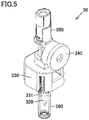
- Fig. 5 is a perspective view of the first coupling tool according to Embodiment 1 with one end side of the first coupling tool directed upward.
- Fig. 6 is a perspective view of the first coupling tool according to Embodiment 1 with the other end side of the first coupling tool directed upward.
- Fig. 7 is a sectional view of the first coupling tool according to Embodiment 1. With reference to Figs. 5 to 7 , first coupling tool 30 according to Embodiment 1 will be described.
- First coupling tool 30 includes a tubular portion 310, a puncture needle 320, a vial insertion attachment portion 330, a port 340, and a cap 350.
- Tubular portion 310 is provided on one end side (proximal end side) of first coupling tool 30.
- Tubular portion 310 is configured to accommodate the distal end side of needle 230 (specifically, the distal end side of needle tube 231).
- Tubular portion 310 is covered with cap 350.
- Cap 350 includes a tubular main body 351 and a closing film 352.
- Main body 351 covers tubular portion 310.
- Closing film 352 closes one end side of main body 351 and also closes one end side of tubular portion 310.
- Closing film 352 has a first film body 353 and a second film body 354.
- Closing film 352 is formed of first film body 353 and second film body 354 overlaid in the tube axis direction of cap 350.
- Closing film 352 is formed as an integral elastic member of first film body 353 and second film body 354 layered to keep intimate contact.
- Puncture needle 320 is provided on the other end side (distal end side) of first coupling tool 30. Puncture needle 320 is provided to stick into elastic stopper body 43 of vial 40. Puncture needle 320 is arranged in line with tubular portion 310 along the axis of tubular portion 310.
- Puncture needle 320 has a first hole 321 serving as a liquid hole and a second hole 322. One end side of first hole 321 is connected to the other end side of tubular portion 310. This allows first hole 321 to be in communication with the interior of tubular portion 310. The other end side of first hole 321 is open on the outer peripheral surface of puncture needle 320.
- First hole 321 is preferably formed at a position deviated from the axis center of puncture needle 320. This reduces the generation of an aerosol floating for a long period of time due to direct spraying of liquid drug L to the drug in vial 40 when liquid drug L is transferred from syringe 10 into vial 40.
- Second hole 322 is separate from first hole 321. One end side of second hole 322 is connected to port 340. The other end side of second hole 322 is open on the other end side of puncture needle 320.
- Port 340 serves to dissipate the gas in vial 40 to the outside of the system when the internal pressure of vial 40 rises.
- An aerosol filter 341 is disposed in port 340. Aerosol filter 341 prevents the aerosol which is contained in the gas and contains components of liquid drug L, drug, drug solution, and the like from leaking outside the system.
- a hydrophobic material such as water-repellent resins including polytetrafluoroethylene and ethylene-tetrafluoroethylene, and resins and fibers each having a water-repellent surface.
- the poser size, structure, and thickness of aerosol filter 341 are appropriately selected.
- An aerosol floating for a long period of time usually has a diameter of about 10 nm to 500 nm.
- a hydrophilic filter, a filter having positive or negative electrostatic property, active carbon, or the like may be combined compositely to form aerosol filter 341.
- First coupling tool 30 may have a configuration devoid of aerosol filter 341.
- Vial insertion attachment portion 330 has a tubular shape. Vial insertion attachment portion 330 is provided to be attachable to mouth 42 of vial 40. The inside diameter of vial insertion attachment portion 330 is provided to be slightly smaller than that of mouth 42. With vial insertion attachment portion 330 attached to mouth 42, vial insertion attachment portion 330 is widened outwardly, and the inner peripheral surface of vial insertion attachment portion 330 catches the outer peripheral portion of mouth 42.
- a cutout 331 is provided in vial insertion attachment portion 330. Providing cutout 331 facilitates flexible deformation of vial insertion attachment portion 330, so that vial insertion attachment portion 330 is attached by insertion to mouth 42.
- vial insertion attachment portion 330 The inner peripheral surface of vial insertion attachment portion 330 is provided to be slidable on the outer periphery of mouth 42. With vial insertion attachment portion 330 inserted into mouth 42, first coupling tool 30 can be pushed toward vial 40.
- Vial insertion attachment portion 330 may be shaped integrally with puncture needle 320 and tubular portion 310 described above.
- the material for vial insertion attachment portion 330, puncture needle 320, and tubular portion 310 is preferably ABS resin, SB resin, polycarbonate, or polystyrene.
- First coupling tool 30 may further include a protective cap 360.
- Protective cap 360 protects puncture needle 320.
- Protective cap 360 is removed from puncture needle 320 when first coupling tool 30 is attached to vial 40.
- liquid drug transfer device 100 In use of liquid drug transfer device 100, first, syringe 10 is attached to connector 20.
- Fig. 8 is a sectional view showing a state in which the syringe according to Embodiment 1 is attached to the connector by insertion. As shown in Fig. 8 , in attachment of syringe 10 to connector 20, the distal end side of syringe 10 is inserted from the proximal end side of connector 20 into first inner tube 221 with the distal end of syringe 10 directed upward.
- Syringe 10 is rotated in the screwing direction, and screwing portion 14 of syringe 10 is screwed with spiral groove 226 formed on the outer peripheral side of first inner tube 221, thereby attaching syringe 10 to the connector. Consequently, a connector-attached syringe with connector 20 attached by insertion to the distal end side of syringe 10, which serves as a connector-attached drug container, is provided.
- syringe 10 In the insertion attachment state in which syringe 10 is attached to the connector, syringe 10 can rotate together with inner tube 220 in the screwing direction (DR1) and the unscrewing direction (DR2 direction) as described above.
- Fig. 9 is a bottom view showing a first state of the connector in the insertion attachment state shown in Fig. 8 .
- Fig. 9 shows only connector 20 viewed from the proximal end side and does not show syringe 10.
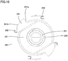
- Fig. 10 is a bottom view showing a second state of the connector in the insertion attachment state shown in Fig. 8 .
- Fig. 10 shows only connector 20 viewed from the proximal end side and does not show syringe 10.
- the holding force by which outer tube 210 holds inner tube 220 is smaller than the frictional force between syringe 10 and inner tube 220 which is required to unscrew syringe 10 from the above insertion attachment state. Consequently, rotating syringe 10 in the unscrewing direction (DR2) in the above insertion attachment state causes syringe 10 to rotate together with inner tube 220 in the unscrewing direction without being unscrewed from inner tube 220.
- Syringe 10 and inner tube 220 rotate freely together relative to outer tube 210 as described above, thus preventing syringe 10 from becoming detached from connector 20. Consequently, a leakage of liquid drug L from the interior of syringe 10 can be prevented.
- FIG. 11 is a sectional view showing the state in which the first coupling tool is connected to the vial according to Embodiment 1. As shown in Fig. 11 , first coupling tool 30 is pressed down toward vial 40 with puncture needle 320 puncturing elastic stopper body 43 of vial 40, thereby attaching vial insertion attachment portion 330 to mouth 42. Consequently, first coupling tool 30 is connected to vial 40.
- syringe 10 may be attached to connector 20 after first coupling tool 30 is connected to vial 40.
- Fig. 12 is a sectional view showing a state in which the connector-attached syringe, the first coupling tool, and the vial according to Embodiment 1 are connected to each other.
- a connector-attached syringe is attached by insertion to first coupling tool 30 connected to vial 40, and vial 40 and connector 20 are coupled to each other through first coupling tool 30.
- first coupling tool 30 is pressed down toward first coupling tool 30 such that the one end side (cap 350 side) of first coupling tool 30 is inserted into outer tube 210 through valve hole 251.
- coating 233 covering needle tube 231 contacts closing film 352 closing the interior of cap 350 and also closing the opening on one end side of tubular portion 310. Further pressing down the connector-attached syringe elastically deforms coating 233, so that needle tube 231 passes through coating 233 and sticks into first film body 353 and second film body 354. As a result, the distal end side of needle 230 (specifically, the distal end side of needle tube 231) is inserted into tubular portion 310. At this time, first film body 353 and second film body 354 adhere to the periphery of needle tube 231, thus allowing hollow passage 231a and the interior of tubular portion 310 to be in communication with each other while keeping the fluid-tight state.
- screwing portion 14 is screwed with spiral groove 226 with the distal end side of nozzle 12 coming in inner tube 220 of connector 20.
- This allows the interior of vial 40, first hole 321, the interior of tubular portion 310, hollow passage 231a of needle 230, the interior of inner tube 220, and the interior of nozzle 12 to be in communication with each other in the state in which connector 20 is attached by insertion to the distal end side of syringe 10 and in the state in which puncture needle 320 sticks into elastic stopper body 43 of vial 40 to cause the distal end side of needle 230 to be inserted into tubular portion 310.
- Pressing down plunger 17 of syringe 10 causes liquid drug L contained in syringe 10 to be transferred into vial 40 so as to be sprayed onto the inner wall of vial 40 through the interior of nozzle 12, the interior of inner tube 220, the interior of hollow passage 231a, the interior of tubular portion 310, and first hole 321.
- vial 40 rises, causing the gas contained in vial 40 to be discharged out of the system from port 340 through second hole 322 formed in puncture needle 320.
- aerosol filter 341 prevents the aerosol generated by spraying of liquid drug L from being discharged out of the system.
- the drug in vial 40 is dissolved in liquid drug L which has been transferred, thereby preparing a desired drug solution.
- liquid drug transfer device 100 and vial 40 are inverted vertically while liquid drug transfer device 100 and vial 40 are kept connected. That is to say, the positions of liquid drug transfer device 100 and vial 40 are changed such that vial 40 is positioned above syringe 10 and syringe 10 is positioned below vial 40.
- Pulling plunger 17 downward in this state causes the drug solution to be transferred from vial 40 into syringe 10 through the interior of vial 40, first hole 321, the interior of tubular portion 310, hollow passage 231a of needle 230, the interior of inner tube 220, and the interior of nozzle 12.
- the drug solution is drawn and taken into syringe 10 up to the nominal capacity.
- the connector-attached syringe is detached from first coupling tool 30 in order to cause the drug solution drawn into syringe 10 to be charged into the liquid drug contained in infusion container 50 (see Fig. 13 ) again.
- the connector-attached syringe is separated away from first coupling tool 30 such that one end side (cap 350 side) of first coupling tool 30 is pulled out of outer tube 210 through valve hole 251.
- needle tube 231 is removed from first film body 353 and second film body 354.
- the drug solution which has adhered to the distal end of needle tube 231 in transfer of the prepared drug solution from vial 40 to syringe 101, remains at the distal end of needle tube 231.
- needle tube 231 When needle tube 231 is removed from first film body 353 and second film body 354, needle tube 231 slides against first film body 353 and second film body 354 with first film body 353 and second film body 354 adhering to the outer peripheral surface of needle tube 231. This causes an action of squeezing needle tube 231 by first film body 353 and second film body 354. Consequently, the drug solution adhering to the outermost surface of needle tube 231 is removed. The drug solution squeezed by first film body 353 and second film body 354 is caught between first film body 353 and second film body 354.
- valve hole 251 of valve 250 is closed.
- the first coupling tool is used separately to couple syringe 10 and the infusion container containing the liquid drug to each other, thereby transferring the drug solution into the infusion container.
- connector 20 allows ratchet mechanism 240 to restrict rotation of inner tube 220 together with syringe 10 in the screwing direction and allow inner tube 220 to rotate freely relative to outer tube 210 together with syringe 10 in the unscrewing direction opposite to the screwing direction in the state in which syringe 10 and connector 20 are connected to each other, that is, the state in which connector 20 is attached by insertion to the distal end of syringe 10. Consequently, syringe 10 cannot be detached from connector 20 in the state in which syringe 10 and connector 20 are connected to each other. This prevents leakage of the liquid drug from syringe 10 due to unintentional detachment of connector 20 from syringe 10.
- needle tube 231 of connector 20 is coated with coating 233, thus preventing leakage of the liquid drug of syringe 10 also from connector 20. Further, providing valve 250 that closes the distal end side of outer tube 210 of connector 20 can further prevent leakage of the liquid drug from connector 20.
- liquid drug transfer device 100 including a connector-attached syringe with connector 20 attached by insertion to the distal end of syringe 10 and the first coupling tool
- syringe 10 is not detached from connector 20 even when liquid drug transfer device 100 is out of position. That is to say, syringe 10 and connector 20 are detached from first coupling tool 30 with syringe 10 connected to connector 20. This prevents leakage of the liquid drug from syringe 10 as described above.
- coating 233 returns to its original state, and coating 233 coats needle tube 231 of connector 20, thus preventing leakage of the liquid drug into syringe 10 from the connector 20 side.
- Fig. 13 is a perspective view showing a state in which a connector-attached syringe, a second coupling tool, and an infusion container according to Embodiment 2 are connected to each other.
- Fig. 14 is a sectional view of components of a liquid drug transfer device and the infusion container according to Embodiment 2. With reference to Figs. 13 and 14 , the components of a liquid drug transfer device 100A and an infusion container 50 according to Embodiment 2 will be described.
- Infusion container 50 contains a liquid drug.
- Infusion container 50 includes a container body 51 having a mouth 52 and an elastic stopper body 53 sealing mouth 52.
- Mouth 52 has a first frame body 521 passing through container body 51 and a second frame body 522 attached to the tip end of first frame body 521.
- First frame body 521 and second frame body 522 have a tubular shape.
- First frame body 521 and second frame body 522 are formed of, for example, a resin member.
- Elastic stopper body 53 is held by second frame body 522.
- Elastic stopper body 53 may be, for example, a rubber member or thermoplastic elastomer resin.
- Liquid drug transfer device 100A uses the drug solution prepared in Embodiment 1 as the liquid drug contained in syringe 10 and causes this drug solution to be transferred to infusion container 50 serving as a drug container.
- Liquid drug transfer device 100A includes connector 20, syringe 10, and a second coupling tool 30A serving as the first coupling tool.
- Syringe 10 has a configuration substantially identical to that of syringe 10 according to Embodiment 1, the configuration of which will be omitted.
- Connector 20 has a configuration substantially identical to that of connector 20 according to Embodiment 1, the configuration of which will be omitted.
- the connector-attached syringe in which syringe 10 is inserted into connector 20 has a configuration substantially identical to that of the connector-attached syringe according to Embodiment 1.
- Second coupling tool 30A has an outlet port 380 formed on one end side and a puncture needle 320A formed on the other end side with respect to an axis, where the axis is the direction in which second coupling tool 30A sticks into the plug body of infusion container 50, and is provided with a tubular portion 310 that projects obliquely from the axis.
- tubular portion 310 of second coupling tool 30A and cap 350 are substantially identical to the configurations of tubular portion 310 of first coupling tool 30 and cap 350.
- Puncture needle 320A is substantially identical to the configuration of puncture needle 320 of first coupling tool 30.
- Puncture needle 320A has a first hole 321A serving as a liquid hole and a second hole 322A.
- First hole 321A is in communication with the interior of tubular portion 310.
- Second hole 322A is separate from first hole 321A.
- Second hole 322A is connected to outlet port 380.
- a closing member 381 that allows a bottle needle of an infusion line to stick thereinto is provided at the tip end of outlet port 35.
- Closing member 381 is usually a thin film having elasticity so that it allows the bottle needle of the infusion line to stick thereinto, does not allow easy disengagemen by the bottle needle in the sticking position, and does not impair the fluid-tightness.
- a material for closing member 381 which satisfies the above performance is determined in view of compatibility with a drug in contact with it, and is appropriately selected from among natural rubber, butyl rubber, chlorinated butyl rubber, styrene butadiene rubber, thermoplastic elastomer, and the like.
- the opening of outlet port 380 preferably has a cylindrical shape having an inside diameter slightly smaller than that of the bottle needle of the infusion line for assisting holding of the bottle needle.
- a liquid valve (not shown) that can bidirectionally open in response to a predetermined pressure or more is disposed at the other end (lower end side in Fig. 14 ) of tubular portion 310.
- the liquid valve is configured to allow first hole 321A and the interior of tubular portion 310 to be in communication with each other.
- the liquid valve opens upon application of a predetermined pressure or more when the drug solution is transferred from syringe 10 to infusion container 50.
- the liquid valve described above may be a one-way valve that allows a flow of liquid from the interior of tubular portion 310 toward first hole 321A and prohibits a flow in the reverse direction so that the drug solution can be irreversibly transferred from syringe 10 to infusion container 50.
- liquid drug transfer device 100A A way of using liquid drug transfer device 100A will now be described.
- second coupling tool 30A is connected to infusion container 50.
- elastic stopper body 53 is punctured with puncture needle 320A.
- the connector-attached syringe that contains the drug solution prepared as described above is attached by insertion to second coupling tool 30A to couple infusion container 50 and connector 20 to each other with second coupling tool 30A therebetween.
- infusion container 50 This allows the interior of infusion container 50, first hole 321A, the interior of tubular portion 310, hollow passage 231a of needle 230, the interior of inner tube 220, and the interior of nozzle 12 to be in communication with each other. Consequently, the drug solution contained in syringe 10 can be transferred into infusion container 50.
- Pressing down plunger 17 of syringe 10 causes the drug solution contained in syringe 10 to be transferred into infusion container 50 through the interior of nozzle 12, the interior of inner tube 220, the interior of hollow passage 231a, the interior of tubular portion 310, and first hole 321. Consequently, a new drug solution is prepared.
- Fig. 15 shows an example of the infusion line according to Embodiment 2.
- an infusion line 400 is formed of infusion container 50, an infusion container 50A, bottle needles 71 and 71A, intravenous chambers 72 and 72A, roller clamps 73 and 73A, tubes 74 and 74A, and connectors 75 and 75A, and the prepared drug solution is administered to a patient.
- connector 20 As described above, connector 20, the connector-attached syringe, and liquid drug transfer device 100A according to Embodiment 2 can also achieve effects substantially identical to those of Embodiment 1.
- ratchet mechanism 240 is formed of ratchet tooth 241 and ratchet pawl 242
- the present invention is not limited thereto.
- Ratchet pawl 242 may be replaced by a ratchet groove that restricts the rotation of a ratchet tooth in one direction and prohibits the rotation in the other direction.
- Ratchet tooth 241 may be provided directly in inner tube 220 as long as the attachment by insertion of the distal end of syringe 10 is not affected.
- ratchet tooth support 260 is formed of inner tube 220.
- Embodiment 1 described above has illustrated the case in which a syringe and a vial are connected to each other as the manner of using a liquid drug transfer device and Embodiment 2 has illustrated the case in which a syringe and an infusion container are connected to each other as the manner of using a liquid drug transfer device
- the liquid drug transfer device of the present invention is not limited to such examples.
- the liquid drug transfer device of the present invention can be used in transfer of any liquid, external leakage of which is desirably prohibited.
- the liquid drug transfer device of the present invention can be used for transferring a liquid containing pathogenic bacteria, bacteria to be prevented from having resistance, or the like.
- the liquid drug transfer device according to the present invention can be appropriately used, for example, for transferring a drug solution from a syringe to a drug bag, for transferring an infusion from an infusion line to an empty syringe for sampling, for transferring a liquid specimen containing pathogenic bacteria from a specimen collecting tool to an inspection kit.
- the liquid drug transfer device according to the present invention can be used for transferring a dangerous solvent such as trichloroethylene or a solution containing an endocrine-disrupting substance.
Abstract
Description
- The present invention relates to a connector, a connector-attached drug container, and a liquid drug transfer device for use in mixing a drug and a liquid drug to prepare a drug solution.
- A conventional liquid drug transfer device is disclosed in, for example, Japanese National Patent Publication No.
2016-511662 - The liquid drug transfer device disclosed in PTL 1 includes a syringe (drug container), a vial with its mouth sealed by an elastic lid, a connecting tool (connector) connected to a distal end of the syringe, and a coupling tool connecting the connecting tool and the vial to each other. The coupling tool has a needle having a liquid hole and sticking into the elastic lid. The connecting tool includes a tubular portion that is screwed with a screwing portion of the syringe and is axially movable relative to the needle. The tubular portion has a hollow passage at one end thereof and a needle insertion attachment portion at the other end thereof. The hollow passage is in communication with the interior of the syringe while being screwed with the syringe. The needle insertion attachment portion can receive the proximal end side of the needle. The liquid hole of the needle is provided so as to be in communication with the hollow passage.
- The needle is stuck into the elastic lid of the vial and is attached to the vial, and subsequently, the syringe is brought closer to the one end side of the tubular portion, thereby screwing the tubular portion with the screwing portion of the syringe. The proximal end side of the needle is inserted into the needle insertion attachment portion of the syringe screwed with the tubular portion, and the syringe is pushed toward the vial. This causes the proximal end side of the needle to enter the tubular portion so as to approach the one end of the tubular portion. At this time, the distal end side of the hollow passage passes through a sealing film provided on the proximal end side of the needle, so that the interior of the syringe and the interior of the vial are in communication with each other through the hollow passage of the tubular portion and the liquid hole of the needle. The liquid drug contained in the syringe is transferred into the drug container, and the liquid drug and the drug contained in the vial are mixed together, thus preparing a drug solution.
- PTL 1: Japanese National Patent Publication No.
2016-511662 - The liquid drug transfer device disclosed in PTL 1, however, has a configuration in which one end side of the tubular portion is screwed with the screwing portion of the syringe to attach the syringe to the connecting tool. Consequently, when the position of the liquid drug transfer device is changed, for example, the syringe and the coupling tool may be unscrewed from each other to cause leakage of the liquid contained in the syringe.
- The present invention has been made in view of the above problem, and has an object to provide a connector, a connector-attached drug container, and a liquid drug transfer device capable of preventing a drug container from becoming detached from a connecting tool.
- A connector according to the present invention includes an outer tube, an inner tube held by the outer tube while being inserted into the outer tube, a fluid channel which has a hollow passage and is fixed to a distal end side of the inner tube and accommodated in the outer tube, and a ratchet mechanism which allows rotation of the inner tube in one direction while restricting rotation of the inner tube in the other direction. The inner tube includes an insertion attachment portion which is provided on a proximal end side of the inner tube and with which a distal end side of a drug container is screwed to be attached thereto by insertion. In an insertion attachment state in which the drug container is attached by insertion to the insertion attachment portion, the ratchet mechanism restricts rotation of the inner tube together with the drug container in a screwing direction and allows the inner tube to rotate freely relative to the outer tube together with the drug container in an unscrewing direction opposite to the screwing direction.
- In the connector according to the present invention, the ratchet mechanism preferably includes a ratchet tooth fixed relative to the inner tube and provided to project radially outwardly of the inner tube, and a ratchet pawl provided on a proximal end side of the outer tube and projecting inwardly of the outer tube from an inner peripheral surface of the outer tube.
- The connector according to the present invention further includes a ratchet tooth support supporting the ratchet tooth. The ratchet tooth support preferably includes a flange projecting radially outwardly from an outer peripheral surface of the inner tube, and a wall extending in a tube axis direction of the inner tube and having one end side connected to the flange and the other end side serving as a free end. The ratchet tooth is preferably provided to project radially outwardly from the wall.
- The connector according to the present invention preferably further includes a valve having a valve hole which is provided so as to open and close and closes a distal end side of the outer tube.
- A connector-attached drug container according to the present invention includes a connector and a drug container. The connector includes an outer tube, an inner tube held by the outer tube while being inserted into the outer tube, a fluid channel which has a hollow passage and is fixed to a distal end side of the inner tube and accommodated in the outer tube, and a ratchet mechanism which allows rotation of the inner tube in one direction while restricting rotation of the inner tube in the other direction. The drug container includes a tubular container and a plunger inserted from a proximal end side of the tubular container. The tubular container has a nozzle provided on a distal end side of the tubular container and a surrounding portion surrounding at least a proximal end side of the nozzle, and contains a liquid drug. The inner tube includes an insertion attachment portion which is provided on a proximal end side of the inner tube and with which a distal end side of the drug container is screwed to be attached thereto by insertion. The surrounding portion has a screwing portion screwed with the insertion attachment portion of the connector. In an insertion attachment state in which the drug container is attached by insertion to the insertion attachment portion, the ratchet mechanism restricts rotation of the inner tube together with the drug container in a screwing direction and allows the inner tube to rotate freely relative to the outer tube together with the drug container in an unscrewing direction opposite to the screwing direction. With the distal end side of the nozzle coming in the inner tube of the connector, the screwing portion is screwed with the insertion attachment portion to connect the connector to the distal end side of the drug container.
- A liquid drug transfer device according to the present invention includes a connector, a first coupling tool, and a drug container. The connector includes an outer tube, an inner tube held by the outer tube while being inserted into the outer tube, a fluid channel which has a hollow passage and is fixed to a distal end side of the inner tube and accommodated in the outer tube, and a ratchet mechanism which allows rotation of the inner tube in one direction while restricting rotation of the inner tube in the other direction. The first coupling tool has a mouth. The mouth is tightly closed by an elastic stopper body. The first coupling tool couples a vial containing a drug and the connector to each other. The drug container includes a tubular container and a plunger inserted from a proximal end side of the tubular container. The tubular container has a nozzle provided on a distal end side of the tubular container and a surrounding portion surrounding at least a proximal end side of the nozzle, and contains a liquid drug. The inner tube includes an insertion attachment portion which is provided on a proximal end side of the inner tube and with which the distal end side of drug container is screwed to be attached thereto by insertion. The surrounding portion has a screwing portion screwed with the insertion attachment portion of the connector. In an insertion attachment state in which the drug container is attached by insertion to the insertion attachment portion, the ratchet mechanism restricts rotation of the inner tube together with the drug container in a screwing direction and allows the inner tube to rotate freely together with the drug container relative to the outer tube in an unscrewing direction opposite to the screwing direction. The first coupling tool includes a tubular portion which is inserted into a distal end side of the outer tube of the connector to cause a distal end side of the fluid channel to be inserted thereinto, and a puncture needle which has a liquid hole being in communication with an interior of the tubular portion and is provided so as to stick into an elastic stopper body of the vial. In a state in which with the distal end side of the nozzle coming in the inner tube of the connector, the screwing portion is screwed with the insertion attachment portion to connect the connector to the distal end side of the drug container and in a state in which the puncture needle sticks into the elastic stopper body of the vial to insert the distal end side of the fluid channel into the tubular portion, an interior of the vial, the liquid hole, an interior of the tubular portion, the hollow passage of the fluid channel, an interior of the inner tube, and an interior of the nozzle are in communication with each other to allow transfer of the liquid drug contained in the drug container into the vial.
- The present invention can provide a connector, a connector-attached drug container, and a liquid drug transfer device capable of preventing a drug container from becoming detached from a connecting tool.
-
-
Fig. 1 is a sectional view of components of a liquid drug transfer device and a vial according to Embodiment 1. -
Fig. 2 is a perspective view of a connector according to Embodiment 1. -
Fig. 3 is a perspective view showing the interior on the proximal end side of the connector according to Embodiment 1. -
Fig. 4 is a sectional view of the connector according to Embodiment 1. -
Fig. 5 is a perspective view of a first coupling tool according to Embodiment 1 with one end side of the first coupling tool directed upward. -
Fig. 6 is a perspective view of the first coupling tool according to Embodiment 1 with the other end side of the first coupling tool directed upward. -
Fig. 7 is a sectional view of the first coupling tool according to Embodiment 1. -
Fig. 8 is a sectional view showing a state in which a syringe according to Embodiment 1 is attached by insertion to the connector. -
Fig. 9 is a bottom view showing a first state of the connector in the insertion attachment state shown inFig. 8 . -
Fig. 10 is a bottom view showing a second state of the connector in the insertion attachment state shown inFig. 8 . -
Fig. 11 is a sectional view showing a state in which the first coupling tool according to Embodiment 1 is connected to the vial. -
Fig. 12 is a sectional view showing a state in which a connector-attached syringe, the first coupling tool, and the vial according to Embodiment 1 are connected to each other. -
Fig. 13 is a perspective view showing a state in which a connector-attached syringe, a second coupling tool, and an infusion container according to Embodiment 2 are connected to each other. -
Fig. 14 is a sectional view of components of a liquid drug transfer device and the infusion container according to Embodiment 2. -
Fig. 15 shows an example infusion line according to Embodiment 2. - Embodiments of the present invention will be hereinafter described in detail with reference to the drawings. In the embodiments described below, the same or common components are designated by the same reference characters, and description thereof will not be repeated.
-
Fig. 1 is a sectional view of components of a liquid drug transfer device and a vial according to Embodiment 1. With reference toFig. 1 , the liquid drug transfer device according to Embodiment 1 will be described. - A liquid
drug transfer device 100 according to Embodiment 1 connects asyringe 10 serving as a drug container, aconnector 20 serving as a connecting tool, afirst coupling tool 30 serving as a first coupling tool, and avial 40 to each other to cause the interior ofsyringe 10 and the interior ofvial 40 to be in communication with each other, allows a liquid drug L contained insyringe 10 to be transferred intovial 40, and mixes a drug (not shown) contained invial 40 and liquid drug L invial 40, thereby preparing a drug solution. - As shown in
Fig. 1 , liquiddrug transfer device 100 according to Embodiment 1 includessyringe 10,connector 20, andfirst coupling tool 30. -
Syringe 10 includes atubular container 11 which is open at its opposite ends, and aplunger 17.Tubular container 11 contains liquid drug L. Liquid drug L is an object to be contained which forms a drug.Tubular container 11 has anozzle 12 provided on its distal end side and a surroundingportion 13 surroundingnozzle 12. A screwingportion 14 having a spiral shape is provided on the inner peripheral surface of surroundingportion 13. -
Plunger 17 is inserted intotubular container 11 from the proximal end side oftubular container 11. Agasket 16 is provided on the distal end side ofplunger 17.Gasket 16 is provided to be freely slidable withintubular container 11 and keeps the inner peripheral surface oftubular container 11 andgasket 16 liquid tight. Liquid drug L is contained in the space defined bytubular container 11 andgasket 16.Gasket 16 may be, for example, natural rubber, butyl rubber, chlorinated butyl rubber, ethylene-butadiene rubber, or thermoplastic elastomer. -
Vial 40 contains a drug (not shown).Vial 40 includes acontainer body 41 having amouth 42, and anelastic stopper body 43 sealingmouth 42.Container body 41 may be, for example, a glass container or a resin container.Elastic stopper body 43 may be, for example, a rubber member or a thermoplastic elastomer resin. -
Fig. 2 is a perspective view of the connector according to Embodiment 1.Fig. 3 is a perspective view showing the interior on the proximal end side of the connector according to Embodiment 1.Fig. 4 is a sectional view of the connector according to Embodiment 1. With reference toFigs. 2 to 4 ,connector 20 serving as the connecting tool according to Embodiment 1 will be described. -
Connector 20 includes anouter tube 210, aninner tube 220, aneedle 230, aratchet mechanism 240, avalve 250, and aratchet tooth support 260. -
Outer tube 210 includes a firstouter tube 211, a secondouter tube 212, and a thirdouter tube 213. Firstouter tube 211 is located on the distal end side ofouter tube 210. Firstouter tube 211 accommodates the distal end side ofinner tube 220 and the distal end side ofneedle 230. Firstouter tube 211 is configured to allow one end side offirst coupling tool 30, more specifically, atubular portion 310 side (cap 350 side) offirst coupling tool 30, which will be described below, to be inserted thereinto. - A
lid 215 is attached to adistal end 211a of firstouter tube 211.Lid 215 has an annular shape. A through-hole 216 passing throughlid 215 thicknesswise is formed in the center portion oflid 215. - Through-
hole 216 has an outside diameter slightly greater than the outside diameter ofcap 350 offirst coupling tool 30, which will be described below. Consequently, in coupling ofconnector 20 tofirst coupling tool 30,cap 350 and accordinglytubular portion 310 are positioned to allowneedle tube 231 ofneedle 230 to be reliably guided intotubular portion 310. -
Valve 250 is sandwiched betweenlid 215 anddistal end 211a of firstouter tube 211.Valve 250 closes the distal end side ofouter tube 210.Valve 250 has avalve hole 251 provided to open and close in accordance with the insertion and removal of the one end side (cap 350 side) offirst coupling tool 30.Valve hole 251 is provided like a slit. -
Valve 250 is formed of an elastic member. The material for the elastic member ofvalve 250 may be any appropriate material that can restore its original shape when a load exerted onvalve 250 is removed. For example, the material may be a rubber material such as isoprene rubber, butyl rubber, or silicone rubber. - Second
outer tube 212 is located between firstouter tube 211 and thirdouter tube 213 and connects firstouter tube 211 and thirdouter tube 213 to each other. The inside diameter of secondouter tube 212 is greater than the inside diameter of firstouter tube 211. Secondouter tube 212 accommodates a middle portion of inner tube 220 (specifically, the proximal end side of second inner tube 222), which will be described below, a hittingportion 223, which will be described below, and an O-ring 270. - Third
outer tube 213 is located on the proximal end side ofouter tube 210. Thirdouter tube 213 mainly accommodates the proximal end side ofinner tube 220. The inside diameter of thirdouter tube 213 is greater than the inside diameter of secondouter tube 212. Thirdouter tube 213 allows aratchet tooth 241, which will be described below, to rotate around the central axis ofouter tube 210. -
Inner tube 220 is held byouter tube 210 while being inserted intoouter tube 210. The tube axis ofinner tube 220 coincides with the tube axis ofouter tube 210.Inner tube 220 is held byouter tube 210 so as to rotate around the tube axis ofinner tube 220. - Specifically, O-
ring 270 is press-fitted betweeninner tube 220 andouter tube 210, so thatinner tube 220 is rotatably held by the outer tube. O-ring 270 is located between aflange 261 and hittingportion 223 in the tube axis direction. This prevents O-ring 270 from becoming detached frominner tube 220. -
Inner tube 220 has a firstinner tube 221 and a secondinner tube 222. Firstinner tube 221 has a tubular shape. Firstinner tube 221 is provided on the proximal end side ofinner tube 220. Firstinner tube 221 is mainly located inside thirdouter tube 213. - A
spiral protrusion 225 is provided on the outer peripheral surface of firstinner tube 221. Aspiral groove 226 is formed alongspiral protrusion 225.Spiral groove 226 is screwed with screwingportion 14 ofsyringe 10. Firstinner tube 221 functions as an insertion attachment portion with which the distal end side ofsyringe 10 is screwed to be attached thereto by insertion. - Second
inner tube 222 has a tubular shape. Secondinner tube 222 is provided on the distal end side ofinner tube 220. The interior of secondinner tube 222 is in communication with the interior of firstinner tube 221. Secondinner tube 222 is inserted into secondouter tube 212 and firstouter tube 211. Aneedle hub 232 ofneedle 230, which will be described below, is inserted into secondinner tube 222. - Hitting
portion 223 is provided on the outer periphery of secondinner tube 222. Hittingportion 223 has an annular shape. Hittingportion 223 projects radially outwardly from the outer peripheral surface of secondinner tube 222. - Hitting
portion 223 hits the end on the proximal end side of firstouter tube 211. Consequently,inner tube 220 is positioned. -
Needle 230 is fixed to the distal end side ofinner tube 220 and is accommodated inouter tube 210.Needle 230 includes aneedle tube 231 having ahollow passage 231a andneedle hub 232 holdingneedle tube 231.Hollow passage 231a is configured to allow a fluid to flow therethrough. In this manner,needle 230 havinghollow passage 231a is configured to allow a liquid drug to flow therethrough and functions as a fluid channel. -
Needle hub 232 has a closed tubular shape.Needle hub 232 is attached to secondinner tube 222. Withneedle hub 232 attached to secondinner tube 222, the interior ofneedle hub 232 is in fluid-tight communication with the interior of firstinner tube 221. -
Hollow passage 231a ofneedle tube 231 is in fluid-tight communication with the interior of firstinner tube 221 through the interior ofneedle hub 232. -
Needle tube 231 is coated with acoating 233. Coating 233 is formed of, for example, a rubber cap. Coating 233 is elastically provided. Coating 233 is provided to allowneedle tube 231 to stick thereinto. -
Ratchet mechanism 240 restricts rotation ofinner tube 220 together withsyringe 10 in the screwing direction (DR1 direction) in the insertion attachment state in which the distal end of the syringe is attached by insertion to first inner tube 221 (insertion attachment portion). -
Ratchet mechanism 240 allowsinner tube 220 to rotate freely relative toouter tube 210 together withsyringe 10 in the unscrewing direction (DR2 direction) in the above insertion attachment state. The screwing direction is a direction in whichsyringe 10 is rotated when the distal end side ofsyringe 10 is screwed withinner tube 220, and the unscrewing direction is opposite to the screwing direction. -
Ratchet mechanism 240 has ratchetteeth 241 and a plurality ofratchet pawls 242. - Ratchet
pawls 242 have, for example, a plate shape. Ratchetpawls 242 extend along the tube axis ofouter tube 210. Ratchetpawls 242 are provided to project from the inner peripheral surface of thirdouter tube 213 toward the interior of thirdouter tube 213. Ratchetpawls 242 are circumferentially provided at pitches of 90°. Ratchetpawls 242 are provided to project in different directions. The directions in which ratchet pawls 242 adjacent to each other anticlockwise project differ by 90° around the central axis ofouter tube 210. - Ratchet
teeth 241 are provided to project radially outwardly ofinner tube 220. Specifically, each ofratchet teeth 241 is provided to project radially outwardly ofinner tube 220 from acorresponding wall 262, which will be described below. -
Ratchet tooth 241 includes a hittingportion 241a that can hit against atip 242a ofratchet pawl 242 and acurved portion 241b slidable towardratchet pawl 242. - Hitting
portion 241a hits againsttip 242a ofratchet pawl 242 when the distal end ofsyringe 10 is screwed to inner tube 220 (specifically, first inner tube 221) andsyringe 10 is then rotated further in the screwing direction (DR1 direction). This restricts rotation ofinner tube 220 together withsyringe 10 in the screwing direction (DR1 direction) in the insertion attachment state described above. -
Curved portion 241b is generally formed in a fan shape and is configured to be slidable towardratchet pawl 242 located forward in the rotation direction in the unscrewing direction (DR2 direction). - The holding force by which
outer tube 210 holdsinner tube 220 is smaller than the frictional force betweensyringe 10 andinner tube 220 which is required to unscrewsyringe 10 from the insertion attachment state in which the distal end ofsyringe 10 is attached to firstinner tube 221. - Thus, rotating
syringe 10 in the unscrewing direction in the above insertion attachment state causessyringe 10 to rotate in the unscrewing direction together withinner tube 220 without being unscrewed frominner tube 220. At this time,ratchet tooth 241 slides towardratchet pawl 242, which allowsinner tube 220 to rotate freely relative toouter tube 210 together withsyringe 10 in the unscrewing direction (DR2 direction). - Each of
ratchet teeth 241 is fixed relative toinner tube 220. Ratchetteeth 241 are supported byratchet tooth support 260.Ratchet tooth support 260 includesflange 261 andwalls 262. -
Flange 261 projects radially outwardly of firstinner tube 221 from the outer peripheral surface of firstinner tube 221.Flange 261 has an approximately annular shape. -
Walls 262 extend along the tube axis ofinner tube 220. One end side of each ofwalls 262 is connected to the peripheral portion offlange 261. The other end side of each ofwalls 262 is a free end. This allowswalls 262 to flexibly deform. In the insertion attachment state ofsyringe 10, whensyringe 10 is rotated in the unscrewing direction, flexible deformation ofwall 262 reduces a sliding resistance betweenratchet tooth 241 and ratchetpawl 242, thereby facilitating the rotations ofsyringe 10 andinner tube 220. -
Walls 262 are spaced circumferentially.Walls 262 are provided corresponding to the number ofratchet teeth 241. -
Fig. 5 is a perspective view of the first coupling tool according to Embodiment 1 with one end side of the first coupling tool directed upward.Fig. 6 is a perspective view of the first coupling tool according to Embodiment 1 with the other end side of the first coupling tool directed upward.Fig. 7 is a sectional view of the first coupling tool according to Embodiment 1. With reference toFigs. 5 to 7 ,first coupling tool 30 according to Embodiment 1 will be described. -
First coupling tool 30 includes atubular portion 310, apuncture needle 320, a vialinsertion attachment portion 330, aport 340, and acap 350. -
Tubular portion 310 is provided on one end side (proximal end side) offirst coupling tool 30.Tubular portion 310 is configured to accommodate the distal end side of needle 230 (specifically, the distal end side of needle tube 231).Tubular portion 310 is covered withcap 350. -
Cap 350 includes a tubularmain body 351 and aclosing film 352.Main body 351 coverstubular portion 310.Closing film 352 closes one end side ofmain body 351 and also closes one end side oftubular portion 310. -
Closing film 352 has afirst film body 353 and asecond film body 354.Closing film 352 is formed offirst film body 353 andsecond film body 354 overlaid in the tube axis direction ofcap 350. The surface offirst film body 353, which is located on thesecond film body 354 side, and the surface ofsecond film body 354, which is located on thefirst film body 353 side, adhere to each other.Closing film 352 is formed as an integral elastic member offirst film body 353 andsecond film body 354 layered to keep intimate contact. -
Puncture needle 320 is provided on the other end side (distal end side) offirst coupling tool 30.Puncture needle 320 is provided to stick intoelastic stopper body 43 ofvial 40.Puncture needle 320 is arranged in line withtubular portion 310 along the axis oftubular portion 310. -
Puncture needle 320 has afirst hole 321 serving as a liquid hole and asecond hole 322. One end side offirst hole 321 is connected to the other end side oftubular portion 310. This allowsfirst hole 321 to be in communication with the interior oftubular portion 310. The other end side offirst hole 321 is open on the outer peripheral surface ofpuncture needle 320. -
First hole 321 is preferably formed at a position deviated from the axis center ofpuncture needle 320. This reduces the generation of an aerosol floating for a long period of time due to direct spraying of liquid drug L to the drug invial 40 when liquid drug L is transferred fromsyringe 10 intovial 40. -
Second hole 322 is separate fromfirst hole 321. One end side ofsecond hole 322 is connected toport 340. The other end side ofsecond hole 322 is open on the other end side ofpuncture needle 320. -
Port 340 serves to dissipate the gas invial 40 to the outside of the system when the internal pressure ofvial 40 rises. Anaerosol filter 341 is disposed inport 340.Aerosol filter 341 prevents the aerosol which is contained in the gas and contains components of liquid drug L, drug, drug solution, and the like from leaking outside the system. - Used as the material for
aerosol filter 341 is a hydrophobic material such as water-repellent resins including polytetrafluoroethylene and ethylene-tetrafluoroethylene, and resins and fibers each having a water-repellent surface. The poser size, structure, and thickness ofaerosol filter 341 are appropriately selected. An aerosol floating for a long period of time usually has a diameter of about 10 nm to 500 nm. In consideration of static characteristics or the like of the aerosol, a hydrophilic filter, a filter having positive or negative electrostatic property, active carbon, or the like may be combined compositely to formaerosol filter 341.First coupling tool 30 may have a configuration devoid ofaerosol filter 341. - Vial
insertion attachment portion 330 has a tubular shape. Vialinsertion attachment portion 330 is provided to be attachable tomouth 42 ofvial 40. The inside diameter of vialinsertion attachment portion 330 is provided to be slightly smaller than that ofmouth 42. With vialinsertion attachment portion 330 attached tomouth 42, vialinsertion attachment portion 330 is widened outwardly, and the inner peripheral surface of vialinsertion attachment portion 330 catches the outer peripheral portion ofmouth 42. - A
cutout 331 is provided in vialinsertion attachment portion 330. Providingcutout 331 facilitates flexible deformation of vialinsertion attachment portion 330, so that vialinsertion attachment portion 330 is attached by insertion tomouth 42. - The inner peripheral surface of vial
insertion attachment portion 330 is provided to be slidable on the outer periphery ofmouth 42. With vialinsertion attachment portion 330 inserted intomouth 42,first coupling tool 30 can be pushed towardvial 40. - Vial
insertion attachment portion 330 may be shaped integrally withpuncture needle 320 andtubular portion 310 described above. The material for vialinsertion attachment portion 330,puncture needle 320, andtubular portion 310 is preferably ABS resin, SB resin, polycarbonate, or polystyrene. -
First coupling tool 30 may further include aprotective cap 360.Protective cap 360 protectspuncture needle 320.Protective cap 360 is removed frompuncture needle 320 whenfirst coupling tool 30 is attached tovial 40. - The way of using liquid
drug transfer device 100 will now be described. In use of liquiddrug transfer device 100, first,syringe 10 is attached toconnector 20. -
Fig. 8 is a sectional view showing a state in which the syringe according to Embodiment 1 is attached to the connector by insertion. As shown inFig. 8 , in attachment ofsyringe 10 toconnector 20, the distal end side ofsyringe 10 is inserted from the proximal end side ofconnector 20 into firstinner tube 221 with the distal end ofsyringe 10 directed upward. -
Syringe 10 is rotated in the screwing direction, and screwingportion 14 ofsyringe 10 is screwed withspiral groove 226 formed on the outer peripheral side of firstinner tube 221, thereby attachingsyringe 10 to the connector. Consequently, a connector-attached syringe withconnector 20 attached by insertion to the distal end side ofsyringe 10, which serves as a connector-attached drug container, is provided. - In the insertion attachment state in which
syringe 10 is attached to the connector,syringe 10 can rotate together withinner tube 220 in the screwing direction (DR1) and the unscrewing direction (DR2 direction) as described above. -
Fig. 9 is a bottom view showing a first state of the connector in the insertion attachment state shown inFig. 8 . For convenience's sake,Fig. 9 shows onlyconnector 20 viewed from the proximal end side and does not showsyringe 10. - In the insertion attachment state in which
syringe 10 is attached toconnector 20, rotatingsyringe 10 in the screwing direction (DR1) causessyringe 10 andinner tube 220 to rotate together, so that hittingportion 241a ofratchet tooth 241 hits against the tip ofratchet pawl 242. This state is the first state, and the rotation ofinner tube 220 together withsyringe 10 in the screwing direction (DR1 direction) is restricted in this state. -
Fig. 10 is a bottom view showing a second state of the connector in the insertion attachment state shown inFig. 8 . For convenience's sake,Fig. 10 shows onlyconnector 20 viewed from the proximal end side and does not showsyringe 10. - As described above, the holding force by which
outer tube 210 holdsinner tube 220 is smaller than the frictional force betweensyringe 10 andinner tube 220 which is required to unscrewsyringe 10 from the above insertion attachment state. Consequently, rotatingsyringe 10 in the unscrewing direction (DR2) in the above insertion attachment state causessyringe 10 to rotate together withinner tube 220 in the unscrewing direction without being unscrewed frominner tube 220. - As a result,
curved portion 241b ofratchet tooth 241 abuts against the lateral surface ofratchet pawl 242. This state is the second state. Rotatingsyringe 10 further in the unscrewing direction from this state causescurved portion 241b to start sliding toward the lateral surface ofratchet pawl 242, so thatinner tube 220 rotates in the unscrewing direction. This causesinner tube 220 to rotate freely relative toouter tube 210 together withsyringe 10 in the unscrewing direction. -
Syringe 10 andinner tube 220 rotate freely together relative toouter tube 210 as described above, thus preventingsyringe 10 from becoming detached fromconnector 20. Consequently, a leakage of liquid drug L from the interior ofsyringe 10 can be prevented. - Subsequently,
first coupling tool 30 is connected tovial 40.Fig. 11 is a sectional view showing the state in which the first coupling tool is connected to the vial according to Embodiment 1. As shown inFig. 11 ,first coupling tool 30 is pressed down towardvial 40 withpuncture needle 320 puncturingelastic stopper body 43 ofvial 40, thereby attaching vialinsertion attachment portion 330 tomouth 42. Consequently,first coupling tool 30 is connected tovial 40. - Although description has been given in Embodiment 1 by way of an example in which
syringe 10 is attached toconnector 20 andfirst coupling tool 30 is then connected tovial 40, the present invention is not limited thereto.Syringe 10 may be attached toconnector 20 afterfirst coupling tool 30 is connected tovial 40. -
Fig. 12 is a sectional view showing a state in which the connector-attached syringe, the first coupling tool, and the vial according to Embodiment 1 are connected to each other. As shown inFig. 12 , in connection of the connector-attached syringe,first coupling tool 30, andvial 40, a connector-attached syringe is attached by insertion tofirst coupling tool 30 connected tovial 40, andvial 40 andconnector 20 are coupled to each other throughfirst coupling tool 30. - Specifically, the connector-attached syringe is pressed down toward
first coupling tool 30 such that the one end side (cap 350 side) offirst coupling tool 30 is inserted intoouter tube 210 throughvalve hole 251. - At this time, coating 233 covering
needle tube 231contacts closing film 352 closing the interior ofcap 350 and also closing the opening on one end side oftubular portion 310. Further pressing down the connector-attached syringe elastically deforms coating 233, so thatneedle tube 231 passes throughcoating 233 and sticks intofirst film body 353 andsecond film body 354. As a result, the distal end side of needle 230 (specifically, the distal end side of needle tube 231) is inserted intotubular portion 310. At this time,first film body 353 andsecond film body 354 adhere to the periphery ofneedle tube 231, thus allowinghollow passage 231a and the interior oftubular portion 310 to be in communication with each other while keeping the fluid-tight state. - As a result, screwing
portion 14 is screwed withspiral groove 226 with the distal end side ofnozzle 12 coming ininner tube 220 ofconnector 20. This allows the interior ofvial 40,first hole 321, the interior oftubular portion 310,hollow passage 231a ofneedle 230, the interior ofinner tube 220, and the interior ofnozzle 12 to be in communication with each other in the state in whichconnector 20 is attached by insertion to the distal end side ofsyringe 10 and in the state in whichpuncture needle 320 sticks intoelastic stopper body 43 ofvial 40 to cause the distal end side ofneedle 230 to be inserted intotubular portion 310. This results in the state in which liquid drug L contained insyringe 10 can be transferred intovial 40. - Pressing down
plunger 17 ofsyringe 10 causes liquid drug L contained insyringe 10 to be transferred intovial 40 so as to be sprayed onto the inner wall ofvial 40 through the interior ofnozzle 12, the interior ofinner tube 220, the interior ofhollow passage 231a, the interior oftubular portion 310, andfirst hole 321. - At the same time, the internal pressure of
vial 40 rises, causing the gas contained invial 40 to be discharged out of the system fromport 340 throughsecond hole 322 formed inpuncture needle 320. At this time,aerosol filter 341 prevents the aerosol generated by spraying of liquid drug L from being discharged out of the system. - The drug in
vial 40 is dissolved in liquid drug L which has been transferred, thereby preparing a desired drug solution. - After the preparation of the drug solution, liquid
drug transfer device 100 andvial 40 are inverted vertically while liquiddrug transfer device 100 andvial 40 are kept connected. That is to say, the positions of liquiddrug transfer device 100 andvial 40 are changed such thatvial 40 is positioned abovesyringe 10 andsyringe 10 is positioned belowvial 40. - Pulling
plunger 17 downward in this state causes the drug solution to be transferred fromvial 40 intosyringe 10 through the interior ofvial 40,first hole 321, the interior oftubular portion 310,hollow passage 231a ofneedle 230, the interior ofinner tube 220, and the interior ofnozzle 12. The drug solution is drawn and taken intosyringe 10 up to the nominal capacity. - Subsequently, the connector-attached syringe is detached from
first coupling tool 30 in order to cause the drug solution drawn intosyringe 10 to be charged into the liquid drug contained in infusion container 50 (seeFig. 13 ) again. - Specifically, the connector-attached syringe is separated away from
first coupling tool 30 such that one end side (cap 350 side) offirst coupling tool 30 is pulled out ofouter tube 210 throughvalve hole 251. - At this time,
needle tube 231 is removed fromfirst film body 353 andsecond film body 354. The drug solution, which has adhered to the distal end ofneedle tube 231 in transfer of the prepared drug solution fromvial 40 to syringe 101, remains at the distal end ofneedle tube 231. - When
needle tube 231 is removed fromfirst film body 353 andsecond film body 354,needle tube 231 slides againstfirst film body 353 andsecond film body 354 withfirst film body 353 andsecond film body 354 adhering to the outer peripheral surface ofneedle tube 231. This causes an action of squeezingneedle tube 231 byfirst film body 353 andsecond film body 354. Consequently, the drug solution adhering to the outermost surface ofneedle tube 231 is removed. The drug solution squeezed byfirst film body 353 andsecond film body 354 is caught betweenfirst film body 353 andsecond film body 354. - Further, separating the connector-attached syringe away from
first coupling tool 30 causes coating 233 to restore its original shape andcoat needle tube 231 and also causes one end side offirst coupling tool 30 to be taken out ofouter tube 210. Consequently,valve hole 251 ofvalve 250 is closed. - This reduces leakage of the drug solution transferred into
syringe 10 fromsyringe 10. - In preparation of an anticancer drug as a drug solution, the first coupling tool is used separately to couple
syringe 10 and the infusion container containing the liquid drug to each other, thereby transferring the drug solution into the infusion container. - As described above, the use of
connector 20 according to Embodiment 1 allowsratchet mechanism 240 to restrict rotation ofinner tube 220 together withsyringe 10 in the screwing direction and allowinner tube 220 to rotate freely relative toouter tube 210 together withsyringe 10 in the unscrewing direction opposite to the screwing direction in the state in whichsyringe 10 andconnector 20 are connected to each other, that is, the state in whichconnector 20 is attached by insertion to the distal end ofsyringe 10. Consequently,syringe 10 cannot be detached fromconnector 20 in the state in whichsyringe 10 andconnector 20 are connected to each other. This prevents leakage of the liquid drug fromsyringe 10 due to unintentional detachment ofconnector 20 fromsyringe 10. - In the state before
syringe 10 andconnector 20 are connected tofirst coupling tool 30 withsyringe 10 andconnector 20 connected to each other,needle tube 231 ofconnector 20 is coated withcoating 233, thus preventing leakage of the liquid drug ofsyringe 10 also fromconnector 20. Further, providingvalve 250 that closes the distal end side ofouter tube 210 ofconnector 20 can further prevent leakage of the liquid drug fromconnector 20. - In transfer of the liquid drug contained in
syringe 10 intovial 40 using liquiddrug transfer device 100 including a connector-attached syringe withconnector 20 attached by insertion to the distal end ofsyringe 10 and the first coupling tool,syringe 10 is not detached fromconnector 20 even when liquiddrug transfer device 100 is out of position. That is to say,syringe 10 andconnector 20 are detached fromfirst coupling tool 30 withsyringe 10 connected toconnector 20. This prevents leakage of the liquid drug fromsyringe 10 as described above. - As described above, when
syringe 10 andconnector 20 are detached fromfirst coupling tool 30, coating 233 returns to its original state, andcoating 233 coats needletube 231 ofconnector 20, thus preventing leakage of the liquid drug intosyringe 10 from theconnector 20 side. -
Fig. 13 is a perspective view showing a state in which a connector-attached syringe, a second coupling tool, and an infusion container according to Embodiment 2 are connected to each other.Fig. 14 is a sectional view of components of a liquid drug transfer device and the infusion container according to Embodiment 2. With reference toFigs. 13 and14 , the components of a liquiddrug transfer device 100A and aninfusion container 50 according to Embodiment 2 will be described. -
Infusion container 50 contains a liquid drug.Infusion container 50 includes acontainer body 51 having amouth 52 and anelastic stopper body 53 sealingmouth 52.Mouth 52 has afirst frame body 521 passing throughcontainer body 51 and asecond frame body 522 attached to the tip end offirst frame body 521.First frame body 521 andsecond frame body 522 have a tubular shape.First frame body 521 andsecond frame body 522 are formed of, for example, a resin member. -
Elastic stopper body 53 is held bysecond frame body 522.Elastic stopper body 53 may be, for example, a rubber member or thermoplastic elastomer resin. - Liquid
drug transfer device 100A uses the drug solution prepared in Embodiment 1 as the liquid drug contained insyringe 10 and causes this drug solution to be transferred toinfusion container 50 serving as a drug container. Liquiddrug transfer device 100A includesconnector 20,syringe 10, and asecond coupling tool 30A serving as the first coupling tool. -
Syringe 10 has a configuration substantially identical to that ofsyringe 10 according to Embodiment 1, the configuration of which will be omitted.Connector 20 has a configuration substantially identical to that ofconnector 20 according to Embodiment 1, the configuration of which will be omitted. The connector-attached syringe in whichsyringe 10 is inserted intoconnector 20 has a configuration substantially identical to that of the connector-attached syringe according to Embodiment 1. -
Second coupling tool 30A has anoutlet port 380 formed on one end side and apuncture needle 320A formed on the other end side with respect to an axis, where the axis is the direction in whichsecond coupling tool 30A sticks into the plug body ofinfusion container 50, and is provided with atubular portion 310 that projects obliquely from the axis. - The configurations of
tubular portion 310 ofsecond coupling tool 30A andcap 350 are substantially identical to the configurations oftubular portion 310 offirst coupling tool 30 andcap 350. - The configuration of
puncture needle 320A is substantially identical to the configuration ofpuncture needle 320 offirst coupling tool 30. Punctureneedle 320A has afirst hole 321A serving as a liquid hole and a second hole 322A.First hole 321A is in communication with the interior oftubular portion 310. Second hole 322A is separate fromfirst hole 321A. Second hole 322A is connected tooutlet port 380. A closingmember 381 that allows a bottle needle of an infusion line to stick thereinto is provided at the tip end of outlet port 35. - Closing
member 381 is usually a thin film having elasticity so that it allows the bottle needle of the infusion line to stick thereinto, does not allow easy disengagemen by the bottle needle in the sticking position, and does not impair the fluid-tightness. A material for closingmember 381 which satisfies the above performance is determined in view of compatibility with a drug in contact with it, and is appropriately selected from among natural rubber, butyl rubber, chlorinated butyl rubber, styrene butadiene rubber, thermoplastic elastomer, and the like. The opening ofoutlet port 380 preferably has a cylindrical shape having an inside diameter slightly smaller than that of the bottle needle of the infusion line for assisting holding of the bottle needle. - A liquid valve (not shown) that can bidirectionally open in response to a predetermined pressure or more is disposed at the other end (lower end side in
Fig. 14 ) oftubular portion 310. The liquid valve is configured to allowfirst hole 321A and the interior oftubular portion 310 to be in communication with each other. The liquid valve opens upon application of a predetermined pressure or more when the drug solution is transferred fromsyringe 10 toinfusion container 50. - Contrastingly, when the infusion line is connected to the outlet port of
second coupling tool 30A to transfer the newly prepared drug solution frominfusion container 50 to the infusion line, the pressure falls below the predetermined pressure, closing the liquid valve. This prevents a return of the newly prepared drug solution intosyringe 10 when the newly prepared drug solution is transferred to the infusion line. - The liquid valve described above may be a one-way valve that allows a flow of liquid from the interior of
tubular portion 310 towardfirst hole 321A and prohibits a flow in the reverse direction so that the drug solution can be irreversibly transferred fromsyringe 10 toinfusion container 50. - A way of using liquid
drug transfer device 100A will now be described. In use of liquiddrug transfer device 100A, first,second coupling tool 30A is connected toinfusion container 50. Specifically,elastic stopper body 53 is punctured withpuncture needle 320A. - Subsequently, the connector-attached syringe that contains the drug solution prepared as described above is attached by insertion to
second coupling tool 30A to coupleinfusion container 50 andconnector 20 to each other withsecond coupling tool 30A therebetween. - This allows the interior of
infusion container 50,first hole 321A, the interior oftubular portion 310,hollow passage 231a ofneedle 230, the interior ofinner tube 220, and the interior ofnozzle 12 to be in communication with each other. Consequently, the drug solution contained insyringe 10 can be transferred intoinfusion container 50. - Pressing down
plunger 17 ofsyringe 10 causes the drug solution contained insyringe 10 to be transferred intoinfusion container 50 through the interior ofnozzle 12, the interior ofinner tube 220, the interior ofhollow passage 231a, the interior oftubular portion 310, andfirst hole 321. Consequently, a new drug solution is prepared. -
Fig. 15 shows an example of the infusion line according to Embodiment 2. After the preparation of a new drug solution, as shown inFig. 15 , aninfusion line 400 is formed ofinfusion container 50, an infusion container 50A, bottle needles 71 and 71A,intravenous chambers tubes 74 and 74A, andconnectors - As described above,
connector 20, the connector-attached syringe, and liquiddrug transfer device 100A according to Embodiment 2 can also achieve effects substantially identical to those of Embodiment 1. - Although description has been given in Embodiments 1 and 2 by way of an example in which
ratchet mechanism 240 is formed ofratchet tooth 241 and ratchetpawl 242, the present invention is not limited thereto.Ratchet pawl 242 may be replaced by a ratchet groove that restricts the rotation of a ratchet tooth in one direction and prohibits the rotation in the other direction. - Although description has been given by way of an example in which
ratchet tooth 241 is provided inwall 262 ofratchet tooth support 260, the present invention is not limited thereto.Ratchet tooth 241 may be provided directly ininner tube 220 as long as the attachment by insertion of the distal end ofsyringe 10 is not affected. In this case, ratchettooth support 260 is formed ofinner tube 220. - Although Embodiment 1 described above has illustrated the case in which a syringe and a vial are connected to each other as the manner of using a liquid drug transfer device and Embodiment 2 has illustrated the case in which a syringe and an infusion container are connected to each other as the manner of using a liquid drug transfer device, the liquid drug transfer device of the present invention is not limited to such examples. The liquid drug transfer device of the present invention can be used in transfer of any liquid, external leakage of which is desirably prohibited.
- For example, in addition to dangerous drug such as anti-cancer drug, the liquid drug transfer device of the present invention can be used for transferring a liquid containing pathogenic bacteria, bacteria to be prevented from having resistance, or the like. Specifically, the liquid drug transfer device according to the present invention can be appropriately used, for example, for transferring a drug solution from a syringe to a drug bag, for transferring an infusion from an infusion line to an empty syringe for sampling, for transferring a liquid specimen containing pathogenic bacteria from a specimen collecting tool to an inspection kit. Also, the liquid drug transfer device according to the present invention can be used for transferring a dangerous solvent such as trichloroethylene or a solution containing an endocrine-disrupting substance.
- Although embodiments of the present invention have been described as above, the embodiments disclosed herein are illustrative and non-restrictive in every respect. The scope of the present invention is defined by the terms of the claims, and includes any modification within the meaning and scope equivalent to the terms of the claims.
- 10 syringe, 11 tubular container, 12 nozzle, 13 surrounding portion, 14 screwing portion, 16 gasket, 17 plunger, 20 connector, 30 first coupling tool, 30A second coupling tool, 35 outlet port, 40 vial, 41 container body, 42 mouth, 43 elastic stopper body, 50, 50A infusion container, 51 container body, 52 mouth, 53 elastic stopper body, 71, 71A bottle needle, 72, 72A intravenous chamber, 73, 73A roller clamp, 74, 74A tube, 75, 75A connector, 100, 100A liquid drug transfer device, 210 outer tube, 211 first outer tube, 211a distal end, 212 second outer tube, 213 third outer tube, 215 lid, 216 through-hole, 220 inner tube, 221 first inner tube, 222 second inner tube, 223 hitting portion, 225 projection, 226 groove, 230 needle, 231 needle tube, 231a hollow passage, 232 needle hub, 233 coating, 240 ratchet mechanism, 241 ratchet tooth, 241a hitting portion, 241b curved portion, 242 ratchet pawl, 242a tip, 250 valve, 251 valve hole, 260 ratchet tooth support, 261 flange, 262 wall, 270 O-ring, 310 tubular portion, 320, 320A puncture needle, 321, 321A first hole, 322, 322A second hole, 330 vial insertion attachment portion, 331 cutout, 340 port, 341 aerosol filter, 350 cap, 351 main body, 352 closing film, 353 first film body, 354 second film body, 360 protective cap, 380 outlet port, 381 closing member, 400 infusion line, 521 first frame body, 522 second frame body.
Claims (6)
- A connector comprising:an outer tube;an inner tube held by the outer tube while being inserted into the outer tube;a fluid channel having a hollow passage, the fluid channel being fixed to a distal end side of the inner tube and accommodated in the outer tube; anda ratchet mechanism which allows rotation of the inner tube in one direction while restricting rotation of the inner tube in the other direction, whereinthe inner tube includes an insertion attachment portion which is provided on a proximal end side of the inner tube and with which a distal end side of a drug container is screwed to be attached thereto by insertion, andin an insertion attachment state in which the drug container is attached by insertion to the insertion attachment portion, the ratchet mechanism restricts rotation of the inner tube together with the drug container in a screwing direction and allows the inner tube to rotate freely relative to the outer tube together with the drug container in an unscrewing direction opposite to the screwing direction.
- The connector according to claim 1, wherein the ratchet mechanism includes
a ratchet tooth fixed relative to the inner tube and provided to project radially outwardly of the inner tube, and
a ratchet pawl provided on a proximal end side of the outer tube and projecting inwardly of the outer tube from an inner peripheral surface of the outer tube. - The connector according to claim 2, further comprising a ratchet tooth support supporting the ratchet tooth, wherein
the ratchet tooth support includesa flange projecting radially outwardly from an outer peripheral surface of the inner tube, anda wall extending in a tube axis direction of the inner tube and having one end side connected to the flange and the other end side serving as a free end, andthe ratchet tooth is provided to project radially outwardly from the wall. - The connector according to any one of claims 1 to 3, further comprising a valve having a valve hole provided so as to open and close, the valve closing a distal end side of the outer tube.
- A connector-attached drug container comprising:a connector includingan outer tube,an inner tube held by the outer tube while being inserted into the outer tube,a fluid channel having a hollow passage, the fluid channel being fixed to a distal end side of the inner tube and accommodated in the outer tube, anda ratchet mechanism which allows rotation of the inner tube in one direction while restricting rotation of the inner tube in the other direction;a drug container includinga tubular container having a nozzle provided on a distal end side of the drug container and a surrounding portion surrounding at least a proximal end side of the nozzle, the tubular container containing a liquid drug, anda plunger inserted from a proximal end side of the tubular container, whereinthe inner tube includes an insertion attachment portion which is provided on a proximal end side of the inner tube and with which the distal end side of the drug container is screwed to be attached thereto by insertion,the surrounding portion has a screwing portion screwed with the insertion attachment portion of the connector,in an insertion attachment state in which the drug container is attached by insertion to the insertion attachment portion, the ratchet mechanism restricts rotation of the inner tube together with the drug container in a screwing direction and allows the inner tube to rotate freely relative to the outer tube together with the drug container in an unscrewing direction opposite to the screwing direction, andwith the distal end side of the nozzle coming in the inner tube of the connector, the screwing portion is screwed with the insertion attachment portion to attach the connector by insertion to the distal end side of the drug container.
- A liquid drug transfer device comprising:a connector includingan outer tube,an inner tube held by the outer tube while being inserted into the outer tube,a fluid channel having a hollow passage, the fluid channel being fixed to a distal end side of the inner tube and accommodated in the outer tube, anda ratchet mechanism which allows rotation of the inner tube in one direction while restricting rotation of the inner tube in the other direction;a coupling tool having a mouth, the mouth being tightly closed by an elastic stopper body, the coupling tool coupling a vial containing a drug and the connector to each other; anda drug container includinga tubular container having a nozzle provided on a distal end side of the drug container and a surrounding portion surrounding at least a proximal end side of the nozzle, the tubular container containing a liquid drug, anda plunger inserted from a proximal end side of the tubular container, whereinthe inner tube includes an insertion attachment portion which is provided on a proximal end side of the inner tube and with which the distal end side of the drug container is screwed to be attached thereto by insertion,the surrounding portion has a screwing portion screwed with the insertion attachment portion of the connector,in an insertion attachment state in which the drug container is attached by insertion to the insertion attachment portion, the ratchet mechanism restricts rotation of the inner tube together with the drug container in a screwing direction and allows the inner tube to rotate freely relative to the outer tube together with the drug container in an unscrewing direction opposite to the screwing direction,the coupling tool includesa tubular portion which is inserted into a distal end side of the outer tube of the connector to cause a distal end side of the fluid channel to be inserted thereinto, anda puncture needle which has a liquid hole being in communication with an interior of the tubular portion and is provided so as to stick into an elastic stopper body of the vial,in a state in which with the distal end side of the nozzle coming in the inner tube of the connector, the screwing portion is screwed with the insertion attachment portion to attach the connector by insertion to the distal end side of the drug container and in a state in which the puncture needle sticks into the elastic stopper body of the vial to insert the distal end side of the fluid channel into the tubular portion, an interior of the vial, the liquid hole, an interior of the tubular portion, the hollow passage of the fluid channel, an interior of the inner tube, and an interior of the nozzle are in communication with each other to allow transfer of the liquid drug contained in the drug container into the vial.
Applications Claiming Priority (2)
| Application Number | Priority Date | Filing Date | Title |
|---|---|---|---|
| JP2016156513 | 2016-08-09 | ||
| PCT/JP2017/028978 WO2018030481A1 (en) | 2016-08-09 | 2017-08-09 | Connector, connector-attached medicine container, liquid medicine feeding device |
Publications (3)
| Publication Number | Publication Date |
|---|---|
| EP3498251A1 true EP3498251A1 (en) | 2019-06-19 |
| EP3498251A4 EP3498251A4 (en) | 2020-03-04 |
| EP3498251B1 EP3498251B1 (en) | 2021-04-07 |
Family
ID=61162273
Family Applications (1)
| Application Number | Title | Priority Date | Filing Date |
|---|---|---|---|
| EP17839548.9A Active EP3498251B1 (en) | 2016-08-09 | 2017-08-09 | Connector, connector-attached medicine container, liquid medicine feeding device |
Country Status (4)
| Country | Link |
|---|---|
| EP (1) | EP3498251B1 (en) |
| JP (1) | JP7151481B2 (en) |
| AU (1) | AU2017308385B2 (en) |
| WO (1) | WO2018030481A1 (en) |
Families Citing this family (3)
| Publication number | Priority date | Publication date | Assignee | Title |
|---|---|---|---|---|
| IL257778B (en) * | 2018-02-27 | 2022-07-01 | Equashield Medical Ltd | An apparatus for securing device couplings |
| CN108168986A (en) * | 2018-03-21 | 2018-06-15 | 深圳市鹏医疗仪器有限公司 | Full-automatic liquid-based cell sample manufacturing dyeing all-in-one machine and film-making colouring method |
| AU2020265821B2 (en) | 2019-04-30 | 2023-07-20 | West Pharma. Services IL, Ltd. | Liquid transfer device with dual lumen IV spike |
Family Cites Families (9)
| Publication number | Priority date | Publication date | Assignee | Title |
|---|---|---|---|---|
| CN100460030C (en) | 2002-08-12 | 2009-02-11 | 株式会社Jms | Needle-less port and method of producing the same |
| US8864725B2 (en) * | 2009-03-17 | 2014-10-21 | Baxter Corporation Englewood | Hazardous drug handling system, apparatus and method |
| US8790327B2 (en) * | 2010-03-30 | 2014-07-29 | Terumo Kabushiki Kaisha | Connector and connector assembly |
| EP2959880B1 (en) * | 2010-05-27 | 2017-04-12 | J&J Solutions, Inc. | Closed fluid transfer system |
| JP5804675B2 (en) | 2010-05-27 | 2015-11-04 | 日本コヴィディエン株式会社 | Connector cap and infusion line connection device provided with the same |
| CN103857372A (en) | 2011-10-14 | 2014-06-11 | 诺沃—诺迪斯克保健股份有限公司 | Pre-assembled fluid transfer arrangement |
| TR201810164T4 (en) | 2013-02-07 | 2018-08-27 | Equashield Medical Ltd | Advances in closed drug delivery system. |
| EP4233827A3 (en) | 2014-04-21 | 2023-11-01 | Becton Dickinson and Company Limited | System for closed transfer of fluids |
| CN106413663B (en) | 2014-04-21 | 2019-02-12 | 贝克顿迪金森有限公司 | The syringe adapter being disengaged with compound motion |
-
2017
- 2017-08-09 JP JP2018533546A patent/JP7151481B2/en active Active
- 2017-08-09 EP EP17839548.9A patent/EP3498251B1/en active Active
- 2017-08-09 WO PCT/JP2017/028978 patent/WO2018030481A1/en unknown
- 2017-08-09 AU AU2017308385A patent/AU2017308385B2/en active Active
Also Published As
| Publication number | Publication date |
|---|---|
| JPWO2018030481A1 (en) | 2019-06-13 |
| EP3498251B1 (en) | 2021-04-07 |
| WO2018030481A1 (en) | 2018-02-15 |
| AU2017308385B2 (en) | 2021-12-02 |
| EP3498251A4 (en) | 2020-03-04 |
| AU2017308385A1 (en) | 2019-03-21 |
| JP7151481B2 (en) | 2022-10-12 |
Similar Documents
| Publication | Publication Date | Title |
|---|---|---|
| US20210137789A1 (en) | Connection System for Medical Device Components | |
| JP5680414B2 (en) | Liquid drug delivery device for use with a syringe having an enlarged tip | |
| TWI478708B (en) | Vial adaptors, method of regulating fluid flow through vial adaptor, and method of manufacturing vial adaptor | |
| US8540691B2 (en) | Drug solution transferring device | |
| CN106413800B (en) | Band valve connector for medical conduit line | |
| JP5671661B2 (en) | Vial adapter for use with a syringe having an enlarged distal syringe tip | |
| US7491197B2 (en) | Fluid transfer device | |
| EP3366268B1 (en) | Seal system for cannula | |
| EP3498251B1 (en) | Connector, connector-attached medicine container, liquid medicine feeding device | |
| US10124117B2 (en) | Drug delivery device having cartridge with enlarged distal end | |
| JP3618752B2 (en) | Liquid container with dual-purpose access port | |
| PT2252250E (en) | Vial adapter element | |
| CN107206189A (en) | It is medical to take liquid injector | |
| JP2015521890A (en) | Medical connection device | |
| CA2343343A1 (en) | Adapter for mixing and injection of preparations | |
| CN110446481B (en) | Device for sampling a liquid contained in a container, associated container and use of the container | |
| KR20160106161A (en) | Injection needle covering system | |
| CN112105328A (en) | Connector for connecting a medical injection device to a container | |
| JPH11114065A (en) | Nose lotion spraying adaptor and nose lotion spraying set using the same | |
| JP2012525874A (en) | Improved seal partition device | |
| JP6389230B2 (en) | Medical connection device | |
| US20230173245A1 (en) | Single use cap with sleeve and carrier for needleless connectors |
Legal Events
| Date | Code | Title | Description |
|---|---|---|---|
| STAA | Information on the status of an ep patent application or granted ep patent |
Free format text: STATUS: THE INTERNATIONAL PUBLICATION HAS BEEN MADE |
|
| PUAI | Public reference made under article 153(3) epc to a published international application that has entered the european phase |
Free format text: ORIGINAL CODE: 0009012 |
|
| STAA | Information on the status of an ep patent application or granted ep patent |
Free format text: STATUS: REQUEST FOR EXAMINATION WAS MADE |
|
| 17P | Request for examination filed |
Effective date: 20190306 |
|
| AK | Designated contracting states |
Kind code of ref document: A1 Designated state(s): AL AT BE BG CH CY CZ DE DK EE ES FI FR GB GR HR HU IE IS IT LI LT LU LV MC MK MT NL NO PL PT RO RS SE SI SK SM TR |
|
| AX | Request for extension of the european patent |
Extension state: BA ME |
|
| DAV | Request for validation of the european patent (deleted) | ||
| A4 | Supplementary search report drawn up and despatched |
Effective date: 20200205 |
|
| RIC1 | Information provided on ipc code assigned before grant |
Ipc: A61J 1/20 20060101AFI20200130BHEP |
|
| GRAP | Despatch of communication of intention to grant a patent |
Free format text: ORIGINAL CODE: EPIDOSNIGR1 |
|
| STAA | Information on the status of an ep patent application or granted ep patent |
Free format text: STATUS: GRANT OF PATENT IS INTENDED |
|
| INTG | Intention to grant announced |
Effective date: 20201030 |
|
| GRAS | Grant fee paid |
Free format text: ORIGINAL CODE: EPIDOSNIGR3 |
|
| GRAA | (expected) grant |
Free format text: ORIGINAL CODE: 0009210 |
|
| STAA | Information on the status of an ep patent application or granted ep patent |
Free format text: STATUS: THE PATENT HAS BEEN GRANTED |
|
| AK | Designated contracting states |
Kind code of ref document: B1 Designated state(s): AL AT BE BG CH CY CZ DE DK EE ES FI FR GB GR HR HU IE IS IT LI LT LU LV MC MK MT NL NO PL PT RO RS SE SI SK SM TR |
|
| AX | Request for extension of the european patent |
Extension state: BA ME |
|
| REG | Reference to a national code |
Ref country code: GB Ref legal event code: FG4D |
|
| REG | Reference to a national code |
Ref country code: AT Ref legal event code: REF Ref document number: 1378727 Country of ref document: AT Kind code of ref document: T Effective date: 20210415 Ref country code: CH Ref legal event code: EP |
|
| REG | Reference to a national code |
Ref country code: DE Ref legal event code: R096 Ref document number: 602017036417 Country of ref document: DE |
|
| REG | Reference to a national code |
Ref country code: IE Ref legal event code: FG4D |
|
| REG | Reference to a national code |
Ref country code: LT Ref legal event code: MG9D |
|
| REG | Reference to a national code |
Ref country code: NL Ref legal event code: MP Effective date: 20210407 Ref country code: AT Ref legal event code: MK05 Ref document number: 1378727 Country of ref document: AT Kind code of ref document: T Effective date: 20210407 |
|
| PG25 | Lapsed in a contracting state [announced via postgrant information from national office to epo] |
Ref country code: LT Free format text: LAPSE BECAUSE OF FAILURE TO SUBMIT A TRANSLATION OF THE DESCRIPTION OR TO PAY THE FEE WITHIN THE PRESCRIBED TIME-LIMIT Effective date: 20210407 Ref country code: FI Free format text: LAPSE BECAUSE OF FAILURE TO SUBMIT A TRANSLATION OF THE DESCRIPTION OR TO PAY THE FEE WITHIN THE PRESCRIBED TIME-LIMIT Effective date: 20210407 Ref country code: NL Free format text: LAPSE BECAUSE OF FAILURE TO SUBMIT A TRANSLATION OF THE DESCRIPTION OR TO PAY THE FEE WITHIN THE PRESCRIBED TIME-LIMIT Effective date: 20210407 Ref country code: AT Free format text: LAPSE BECAUSE OF FAILURE TO SUBMIT A TRANSLATION OF THE DESCRIPTION OR TO PAY THE FEE WITHIN THE PRESCRIBED TIME-LIMIT Effective date: 20210407 Ref country code: BG Free format text: LAPSE BECAUSE OF FAILURE TO SUBMIT A TRANSLATION OF THE DESCRIPTION OR TO PAY THE FEE WITHIN THE PRESCRIBED TIME-LIMIT Effective date: 20210707 Ref country code: HR Free format text: LAPSE BECAUSE OF FAILURE TO SUBMIT A TRANSLATION OF THE DESCRIPTION OR TO PAY THE FEE WITHIN THE PRESCRIBED TIME-LIMIT Effective date: 20210407 |
|
| PG25 | Lapsed in a contracting state [announced via postgrant information from national office to epo] |
Ref country code: GR Free format text: LAPSE BECAUSE OF FAILURE TO SUBMIT A TRANSLATION OF THE DESCRIPTION OR TO PAY THE FEE WITHIN THE PRESCRIBED TIME-LIMIT Effective date: 20210708 Ref country code: IS Free format text: LAPSE BECAUSE OF FAILURE TO SUBMIT A TRANSLATION OF THE DESCRIPTION OR TO PAY THE FEE WITHIN THE PRESCRIBED TIME-LIMIT Effective date: 20210807 Ref country code: SE Free format text: LAPSE BECAUSE OF FAILURE TO SUBMIT A TRANSLATION OF THE DESCRIPTION OR TO PAY THE FEE WITHIN THE PRESCRIBED TIME-LIMIT Effective date: 20210407 Ref country code: RS Free format text: LAPSE BECAUSE OF FAILURE TO SUBMIT A TRANSLATION OF THE DESCRIPTION OR TO PAY THE FEE WITHIN THE PRESCRIBED TIME-LIMIT Effective date: 20210407 Ref country code: PL Free format text: LAPSE BECAUSE OF FAILURE TO SUBMIT A TRANSLATION OF THE DESCRIPTION OR TO PAY THE FEE WITHIN THE PRESCRIBED TIME-LIMIT Effective date: 20210407 Ref country code: NO Free format text: LAPSE BECAUSE OF FAILURE TO SUBMIT A TRANSLATION OF THE DESCRIPTION OR TO PAY THE FEE WITHIN THE PRESCRIBED TIME-LIMIT Effective date: 20210707 Ref country code: PT Free format text: LAPSE BECAUSE OF FAILURE TO SUBMIT A TRANSLATION OF THE DESCRIPTION OR TO PAY THE FEE WITHIN THE PRESCRIBED TIME-LIMIT Effective date: 20210809 Ref country code: LV Free format text: LAPSE BECAUSE OF FAILURE TO SUBMIT A TRANSLATION OF THE DESCRIPTION OR TO PAY THE FEE WITHIN THE PRESCRIBED TIME-LIMIT Effective date: 20210407 |
|
| REG | Reference to a national code |
Ref country code: DE Ref legal event code: R097 Ref document number: 602017036417 Country of ref document: DE |
|
| PG25 | Lapsed in a contracting state [announced via postgrant information from national office to epo] |
Ref country code: RO Free format text: LAPSE BECAUSE OF FAILURE TO SUBMIT A TRANSLATION OF THE DESCRIPTION OR TO PAY THE FEE WITHIN THE PRESCRIBED TIME-LIMIT Effective date: 20210407 Ref country code: CZ Free format text: LAPSE BECAUSE OF FAILURE TO SUBMIT A TRANSLATION OF THE DESCRIPTION OR TO PAY THE FEE WITHIN THE PRESCRIBED TIME-LIMIT Effective date: 20210407 Ref country code: EE Free format text: LAPSE BECAUSE OF FAILURE TO SUBMIT A TRANSLATION OF THE DESCRIPTION OR TO PAY THE FEE WITHIN THE PRESCRIBED TIME-LIMIT Effective date: 20210407 Ref country code: DK Free format text: LAPSE BECAUSE OF FAILURE TO SUBMIT A TRANSLATION OF THE DESCRIPTION OR TO PAY THE FEE WITHIN THE PRESCRIBED TIME-LIMIT Effective date: 20210407 Ref country code: SM Free format text: LAPSE BECAUSE OF FAILURE TO SUBMIT A TRANSLATION OF THE DESCRIPTION OR TO PAY THE FEE WITHIN THE PRESCRIBED TIME-LIMIT Effective date: 20210407 Ref country code: SK Free format text: LAPSE BECAUSE OF FAILURE TO SUBMIT A TRANSLATION OF THE DESCRIPTION OR TO PAY THE FEE WITHIN THE PRESCRIBED TIME-LIMIT Effective date: 20210407 Ref country code: ES Free format text: LAPSE BECAUSE OF FAILURE TO SUBMIT A TRANSLATION OF THE DESCRIPTION OR TO PAY THE FEE WITHIN THE PRESCRIBED TIME-LIMIT Effective date: 20210407 |
|
| PLBE | No opposition filed within time limit |
Free format text: ORIGINAL CODE: 0009261 |
|
| STAA | Information on the status of an ep patent application or granted ep patent |
Free format text: STATUS: NO OPPOSITION FILED WITHIN TIME LIMIT |
|
| 26N | No opposition filed |
Effective date: 20220110 |
|
| REG | Reference to a national code |
Ref country code: CH Ref legal event code: PL |
|
| PG25 | Lapsed in a contracting state [announced via postgrant information from national office to epo] |
Ref country code: MC Free format text: LAPSE BECAUSE OF FAILURE TO SUBMIT A TRANSLATION OF THE DESCRIPTION OR TO PAY THE FEE WITHIN THE PRESCRIBED TIME-LIMIT Effective date: 20210407 |
|
| REG | Reference to a national code |
Ref country code: BE Ref legal event code: MM Effective date: 20210831 |
|
| PG25 | Lapsed in a contracting state [announced via postgrant information from national office to epo] |
Ref country code: LI Free format text: LAPSE BECAUSE OF NON-PAYMENT OF DUE FEES Effective date: 20210831 Ref country code: CH Free format text: LAPSE BECAUSE OF NON-PAYMENT OF DUE FEES Effective date: 20210831 |
|
| PG25 | Lapsed in a contracting state [announced via postgrant information from national office to epo] |
Ref country code: IS Free format text: LAPSE BECAUSE OF FAILURE TO SUBMIT A TRANSLATION OF THE DESCRIPTION OR TO PAY THE FEE WITHIN THE PRESCRIBED TIME-LIMIT Effective date: 20210807 Ref country code: LU Free format text: LAPSE BECAUSE OF NON-PAYMENT OF DUE FEES Effective date: 20210809 Ref country code: AL Free format text: LAPSE BECAUSE OF FAILURE TO SUBMIT A TRANSLATION OF THE DESCRIPTION OR TO PAY THE FEE WITHIN THE PRESCRIBED TIME-LIMIT Effective date: 20210407 |
|
| PG25 | Lapsed in a contracting state [announced via postgrant information from national office to epo] |
Ref country code: IT Free format text: LAPSE BECAUSE OF FAILURE TO SUBMIT A TRANSLATION OF THE DESCRIPTION OR TO PAY THE FEE WITHIN THE PRESCRIBED TIME-LIMIT Effective date: 20210407 Ref country code: IE Free format text: LAPSE BECAUSE OF NON-PAYMENT OF DUE FEES Effective date: 20210809 Ref country code: BE Free format text: LAPSE BECAUSE OF NON-PAYMENT OF DUE FEES Effective date: 20210831 |
|
| PG25 | Lapsed in a contracting state [announced via postgrant information from national office to epo] |
Ref country code: CY Free format text: LAPSE BECAUSE OF FAILURE TO SUBMIT A TRANSLATION OF THE DESCRIPTION OR TO PAY THE FEE WITHIN THE PRESCRIBED TIME-LIMIT Effective date: 20210407 |
|
| PG25 | Lapsed in a contracting state [announced via postgrant information from national office to epo] |
Ref country code: HU Free format text: LAPSE BECAUSE OF FAILURE TO SUBMIT A TRANSLATION OF THE DESCRIPTION OR TO PAY THE FEE WITHIN THE PRESCRIBED TIME-LIMIT; INVALID AB INITIO Effective date: 20170809 |
|
| PGFP | Annual fee paid to national office [announced via postgrant information from national office to epo] |
Ref country code: GB Payment date: 20230822 Year of fee payment: 7 |
|
| PGFP | Annual fee paid to national office [announced via postgrant information from national office to epo] |
Ref country code: FR Payment date: 20230828 Year of fee payment: 7 Ref country code: DE Payment date: 20230821 Year of fee payment: 7 |