EP3498144B1 - Floor cleaning robot - Google Patents
Floor cleaning robot Download PDFInfo
- Publication number
- EP3498144B1 EP3498144B1 EP18211741.6A EP18211741A EP3498144B1 EP 3498144 B1 EP3498144 B1 EP 3498144B1 EP 18211741 A EP18211741 A EP 18211741A EP 3498144 B1 EP3498144 B1 EP 3498144B1
- Authority
- EP
- European Patent Office
- Prior art keywords
- bumpers
- bumper
- stage
- cleaning robot
- robot according
- Prior art date
- Legal status (The legal status is an assumption and is not a legal conclusion. Google has not performed a legal analysis and makes no representation as to the accuracy of the status listed.)
- Active
Links
Images


Classifications
-
- A—HUMAN NECESSITIES
- A47—FURNITURE; DOMESTIC ARTICLES OR APPLIANCES; COFFEE MILLS; SPICE MILLS; SUCTION CLEANERS IN GENERAL
- A47L—DOMESTIC WASHING OR CLEANING; SUCTION CLEANERS IN GENERAL
- A47L9/00—Details or accessories of suction cleaners, e.g. mechanical means for controlling the suction or for effecting pulsating action; Storing devices specially adapted to suction cleaners or parts thereof; Carrying-vehicles specially adapted for suction cleaners
- A47L9/28—Installation of the electric equipment, e.g. adaptation or attachment to the suction cleaner; Controlling suction cleaners by electric means
- A47L9/2805—Parameters or conditions being sensed
- A47L9/2826—Parameters or conditions being sensed the condition of the floor
-
- A—HUMAN NECESSITIES
- A47—FURNITURE; DOMESTIC ARTICLES OR APPLIANCES; COFFEE MILLS; SPICE MILLS; SUCTION CLEANERS IN GENERAL
- A47L—DOMESTIC WASHING OR CLEANING; SUCTION CLEANERS IN GENERAL
- A47L2201/00—Robotic cleaning machines, i.e. with automatic control of the travelling movement or the cleaning operation
- A47L2201/04—Automatic control of the travelling movement; Automatic obstacle detection
Definitions
- the present invention relates generally to a floor cleaning robot, and in particular to an autonomous floor cleaning robot provided with means for collecting and / or vacuuming the waste.
- Such an architecture is suitable for a cleaning robot having a limited height, typically less than 5 cm, but it is less suitable for a cleaning robot of greater height, in particular for a “2 in 1” cleaning robot designed to operate. either independently or manually after connecting the robot to a flexible suction tube. In fact, in this case, it is not certain that the cleaning robot detects an obstacle located at a certain altitude from the ground. This results in non-detection of the obstacle and a blocking of the cleaning robot against this obstacle.
- WO2008105634A1 discloses a cleaning robot with 2 bumpers arranged one above the other.
- An aim of the present invention is to respond to the drawbacks of the prior art mentioned above and in particular, first of all, to provide a cleaning robot which allows the detection of any obstacle, whatever the height of the robot. cleaning and whatever the altitude of the obstacle.
- the robot is equipped with one or more displacement members, such as wheels, which come to rest on the ground in operation.
- the plane tangent to the displacement members (for example the wheels) defines the ground support plane of the robot.
- the invention proposes to equip the cleaning robot with a double stage of bumpers and thus to distribute the bumpers over two different heights or altitudes. It thus offers a simple technical solution to enable a cleaning robot, in particular a high-rise cleaning robot, to improve the detection of obstacles located higher or lower. The detection sensitivity of the cleaning robot is thus improved.
- At least one of the floors comprises several bumpers.
- each of the two floors comprises several bumpers.
- one of the stages comprises several bumpers and the other stage comprises a single bumper.
- the stage (s) with several bumpers comprise two side bumpers arranged on either side of a median plane of the robot, perpendicular to the bearing plane on the ground.
- a central bumper is interposed between the two side bumpers.
- the central bumper may have two oblique side flanks, oriented towards the two side bumpers respectively, connecting an inner face and an outer face of the central bumper, said outer face being widened relative to said inner face.
- Such a configuration makes it possible to limit, or even eliminate, the dead non-detection zones situated at the interstices between the central bumper and the side bumpers.
- the enlarged outer face of the central bumper makes it possible to cover, at least partially, these dead non-detection zones.
- a normal to the bearing plane on the ground which passes through a zone of separation between two neighboring bumpers of one stage passes through a bumper of the other stage.
- the outer surface of the bumper (s) of a first of the two floors is set back relative to an envelope surface perpendicular to the bearing plane on the ground and tangent to the outer surface of the bumper (s). - shocks from the second stage, towards the interior of the robot. Thanks to this, in the event of an obstacle hitting the robot over its entire height (a wall for example), unnecessary multiplication of the contact force during the collision is avoided, which makes it possible to limit wear and / or the risk. decrease in robot detection sensitivity.
- a remote presence detection device is advantageously interposed between the two stages. To this end, the two stages leave between them sufficient space to house the presence detection device.
- the obstacle detection by contact using the bumpers is thus supplemented by obstacle detection using one or more proximity sensors, before contact with the obstacle.
- the device for detecting a bumper of one of the two stages is connected in parallel with the device for detecting the associated bumper of the other stage to a unit or an electronic control circuit. Thanks to this, whether a collision with an obstacle is detected in the upper part or in the lower part or else both in the upper and lower parts by the movement detection means, the robot makes no difference. It interprets the detection information as contact with an obstacle in the same area of its circumference and initiates an appropriate release action.
- the figure 1 represents a perspective view of a cleaning robot 100, according to a first particular embodiment of the invention.
- the cleaning robot 100 is intended to clean a floor, for example a floor of a room within a house or a building, independently, that is to say without the intervention of a user while browsing.
- a floor for example a floor of a room within a house or a building
- it comprises a frame 30, drive wheels 31, a suction slot 32, and, inside an outer casing, a waste bin 33, means for storing electrical energy, for example. example a block of rechargeable battery cells 34, and a unit or an electronic circuit (not shown) for controlling the operation and navigation of the cleaning robot 100.
- the drive wheels 31 define a plane P1 of support on the ground ( perpendicular to the plane of the figure 2 ), tangent to the wheels 31 visible on the figure 2 .
- the tangent plane to the wheels 31, which come to rest on the ground defines the ground support plane P1 of the robot.
- the cleaning robot 100 is equipped with several bumpers 10A-10C and 20A-20C mounted to move relative to the frame 30, for example in translation parallel to the ground bearing plane P1.
- the bumpers could be mounted so as to pivot.
- the different bumpers 10A-10C, 20A-20C are mechanically independent from each other. During movement, when the cleaning robot 100 encounters an obstacle, the latter comes into contact with one or more bumpers of the robot and moves the struck bumper or bumpers towards the interior of the robot. In a known manner, elastic means are provided to return the displaced bumper or bumpers to a rest position after release from the obstacle.
- detection means are provided, arranged to detect a movement of each of the bumpers relative to the frame 30 caused by the encounter with an obstacle.
- the control unit is arranged to control a modification of the navigation trajectory of the cleaning robot 100, following the encounter with an obstacle, as a function of the result of detection of a movement of one or more of the barriers.
- shocks 10A-10C and 20A-20C so as to free the robot from the obstacle and continue to navigate around it.
- These detection means comprise a set of detection devices.
- Each bumper 10A-10C, 20A-20C is equipped with one or more detection devices capable of detecting movement of this bumper relative to the frame 30.
- a detection device fitted to a bumper includes an optical sensor block, incorporating a coupled optical transmitter and receiver, and a shutter pivot mechanism intended to cut optical transmission between the transmitter and receiver in the closed position and not to cut this optical transmission between the transmitter and the receiver in the retracted position (outside the closed position).
- Two 21A and 11A shutters are visible on the figure 4 .
- the bumper 10A When the bumper 10A strikes an obstacle (or any other element) during a path of the cleaning robot 100, it moves towards the interior of the robot 100 relative to the frame 30, which causes the shutter to pivot. 11A from its erased position to a closed position in which the optical transmission between the transmitter and the receiver of the optical sensor unit is interrupted.
- the control unit interprets this optical signal cutoff as an indication of an obstacle encountered on the path of the robot.
- cleaning 100 in a zone comprising the considered bumper 10A, and then controls the drive wheels 31 so as to divert the cleaning robot 100 from this obstacle.
- the other detection devices work in the same way.
- the figures 1 and 2 respectively show a front perspective view and a front view of the cleaning robot 100.
- the term "front” here refers to a nominal direction of advance of the cleaning robot 100.
- the bumpers 10A-10C, 20A-20C are arranged on two floors respectively arranged at heights, or altitudes, different with respect to the plane P1 of support on the ground of the robot.
- the bumpers 10A-10C form a first stage and the bumpers 20A-20C form a second stage.
- Each stage comprises a median plane crossing the overall bumpers in their middle and parallel to the ground bearing plane P1.
- the bumpers 10A-10C, 20A-20C here have shapes of cylinder portions having the same central axis AX perpendicular to the plane P1 of bearing on the ground.
- the first stage has a set of three 10A-10C bumpers and the second stage also has a set of three 20A-20C bumpers.
- Each set of three bumpers 10A-10C (20A-20C) comprises two side bumpers 10A, 10C (20A, 20C) arranged on either side of a median plane P2 of the robot 100 (intersecting the robot 100 generally in its middle), perpendicular to the ground bearing plane P1, and a central bumper 10B (20B) located between the two side bumpers 10A, 10C (20A, 20C) and crossed by the median plane P2 of the robot 100.
- Each of the side bumpers 10A, 10C (20A, 20C) is for example equipped with two motion detection devices.
- the central bumper 10B (20B) can be equipped with a single detection device. However, other configurations of the detection means could be considered. In any event, each bumper is equipped with at least one device for detecting movement of said bumper.
- a normal to the ground support plane P1 passing through a zone of separation between two neighboring bumpers of the first stage passes also in a zone of separation between two neighboring bumpers of the second stage (respectively between the two bumpers 20A and 20B or 20B and 20C).
- the respective bumpers of the two stages can be arranged so that 'a normal to the ground bearing plane P1 which passes through a zone of separation between two neighboring bumpers of one stage passes through a bumper of the other stage.
- the central bumper of one of the floors is angularly wider than the central bumper of the other floor.
- the central bumper of one of the stages is angularly offset with respect to the central bumper of the other stage.
- the two stages of bumper 10A-10C and 20A-20C form between them a housing for receiving a presence detection device 40 intended to detect the presence of an obstacle near the robot, without contact.
- the presence detection device 40 is thus interposed between the two stages of bumpers 10A-10C and 20A-20C.
- it has the overall shape of a strip in the form of a cylinder portion with a central axis AX. Its function is to detect the presence of an obstacle near the cleaning robot 100 without the latter coming into contact with the obstacle. It comprises one or more proximity sensors or presence detectors, for example infra-red sensors.
- an envelope surface perpendicular to the ground bearing plane P1 and tangent to the outer surface of the bumper (s) of one of the floors is also tangent to the outer surface of the bumper (s) of the other tier.
- the bumpers of the two floors are thus aligned vertically.
- the invention offers a simple technical solution to improve obstacle detection which is particularly suitable for high robots, typically greater than 5 cm.
- the robot includes three pairs of associated bumpers: 10A and 20A, 10B and 20B, 10C and 20C.
- the device for detecting a bumper of one of the two floors is connected in parallel with the device for detecting the bumper associated with the other floor to the unit. or to the electronic control circuit.
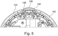
- FIG. 5 there is shown an alternative embodiment of the central bumper of a stage (here the bumper 10B) comprising two oblique side flanks 12B, 13B, oriented towards the two neighboring side bumpers 10A, 10C respectively, connecting a inner face and an outer face of the central bumper 10B.
- the outer face of the central bumper 10B is widened relative to its inner face.
- the geometry of the central bumper 10B is thus improved so as to reduce or even eliminate a dead zone non-detection device located at the gap between two neighboring bumpers 10A-10B and 10B-10C.
- the two stages each include three bumpers 10A-10C and 20A-20C.
- the number of bumpers of a stage may be equal to 2 or be greater than 3.
- these are for example two side bumpers arranged at on either side of the median plane P2 of the robot 100.
- the two stages can also comprise different respective numbers of bumpers, for example two bumpers at the bottom and three bumpers at the top.
- one of the floors has a single bumper and the other floor has several bumpers, for example two bumpers.
- the floor with several bumpers is preferably located between the ground bearing plane P1 and the floor with a single bumper.
- the upper floor has a single bumper and the lower floor has several bumpers, for example two bumpers.
- the single bumper of the first stage makes it possible to cover the detection of a dead non-detection zone located at the separation between the two neighboring bumpers of the second stage.
- the bumpers of the two floors are aligned vertically, as previously explained.
- the outer surface of the bumper (s) of a first of the two floors is set back relative to an envelope surface perpendicular to the plane P1 of bearing on the ground and tangent to the outer surface of the (s). bumper of the second stage, towards the interior of the robot.
- said second stage is located between the plane P1 of ground support and said first floor.
- the top stage of the bumper is set back from the bottom stage of the bumper.
- the shrinkage can be a slight shift of the order of a centimeter, or even a few centimeters. It makes it possible not to increase the contact force caused by an obstacle hitting the robot over its entire height (for example a wall), which would risk reducing the detection sensitivity over time.
- the cleaning robot 100 could have more than two floors so as to cover the entire height of the robot in the event that the latter has a very high height.
Landscapes
- Engineering & Computer Science (AREA)
- Mechanical Engineering (AREA)
- Control Of Position, Course, Altitude, Or Attitude Of Moving Bodies (AREA)
- Electric Vacuum Cleaner (AREA)
- Manipulator (AREA)
Description
La présente invention concerne de manière générale un robot de nettoyage des sols, et en particulier un robot autonome de nettoyage des sols pourvu de moyens de récupération et/ou d'aspiration des déchets.The present invention relates generally to a floor cleaning robot, and in particular to an autonomous floor cleaning robot provided with means for collecting and / or vacuuming the waste.
Il est connu dans l'art antérieur des dispositifs de nettoyage autonomes des sols, et en particulier ceux qui détectent automatiquement les obstacles pour pouvoir ensuite les contourner. De tels dispositifs de nettoyage comprennent généralement un, voire deux, pare-chocs montés mobiles par rapport à un châssis. Le ou les pare-chocs sont équipés d'un ou plusieurs capteurs aptes à détecter un mouvement du pare-chocs lors d'un contact avec un obstacle. Par exemple, on connaît un dispositif de nettoyage, distribué sous la marque « CLEANmaxx® » et dont le nom commercial est « CLEANmaxx 06025 Saugroboter Smart Plus®», comprenant :
- deux pare-chocs avant inférieurs, agencés de part et d'autre d'un plan médian du robot contenant une direction principale d'avancement du robot et une direction normale à un plan d'appui au sol, et
- un bandeau avant supérieur de détection de présence à distance, équipé d'un ou plusieurs détecteurs infra-rouge et destiné à détecter la présence d'un obstacle à proximité, sans contact.
- two lower front bumpers, arranged on either side of a median plane of the robot containing a main direction of advance of the robot and a direction normal to a ground support plane, and
- an upper front panel for remote presence detection, fitted with one or more infrared detectors and intended to detect the presence of an obstacle nearby, without contact.
Une telle architecture est adaptée à un robot de nettoyage ayant une hauteur limitée, typiquement inférieure à 5 cm, mais elle convient moins bien à un robot de nettoyage de plus grande hauteur, notamment à un robot de nettoyage « 2 en 1 » conçu pour fonctionner soit de façon autonome, soit manuellement après raccordement du robot à un tube flexible d'aspiration. En effet, dans ce cas, il n'est pas certain que le robot de nettoyage détecte un obstacle situé à une certaine altitude par rapport au sol. Il en résulte une non-détection de l'obstacle et un blocage du robot de nettoyage contre cet obstacle.Such an architecture is suitable for a cleaning robot having a limited height, typically less than 5 cm, but it is less suitable for a cleaning robot of greater height, in particular for a “2 in 1” cleaning robot designed to operate. either independently or manually after connecting the robot to a flexible suction tube. In fact, in this case, it is not certain that the cleaning robot detects an obstacle located at a certain altitude from the ground. This results in non-detection of the obstacle and a blocking of the cleaning robot against this obstacle.
Un but de la présente invention est de répondre aux inconvénients de l'art antérieur mentionnés ci-dessus et en particulier, tout d'abord, de proposer un robot de nettoyage qui permet la détection de tout obstacle, quelle que soit la hauteur du robot de nettoyage et quelle que soit l'altitude de l'obstacle.An aim of the present invention is to respond to the drawbacks of the prior art mentioned above and in particular, first of all, to provide a cleaning robot which allows the detection of any obstacle, whatever the height of the robot. cleaning and whatever the altitude of the obstacle.
Pour cela un premier aspect de l'invention concerne un robot de nettoyage des sols, comprenant :
- un châssis,
- au moins deux pare-chocs mobiles par rapport au châssis,
- des moyens de détection d'un mouvement de chacun des pare-chocs par rapport au châssis,
- a chassis,
- at least two movable bumpers relative to the chassis,
- means for detecting a movement of each of the bumpers relative to the chassis,
Le robot est équipé d'un ou plusieurs organes de déplacement, tels que des roues, qui viennent reposer sur le sol en fonctionnement. Le plan tangent aux organes de déplacement (par exemple les roues) définit le plan d'appui au sol du robot.The robot is equipped with one or more displacement members, such as wheels, which come to rest on the ground in operation. The plane tangent to the displacement members (for example the wheels) defines the ground support plane of the robot.
L'invention propose d'équiper le robot de nettoyage avec un double étage de pare-chocs et de répartir ainsi les pare-chocs sur deux hauteurs ou altitudes différentes. Elle offre ainsi une solution technique simple pour permettre à un robot de nettoyage, notamment à un robot de nettoyage de grande hauteur, d'améliorer la détection d'obstacles situés plus ou moins haut. La sensibilité de détection du robot de nettoyage est ainsi améliorée.The invention proposes to equip the cleaning robot with a double stage of bumpers and thus to distribute the bumpers over two different heights or altitudes. It thus offers a simple technical solution to enable a cleaning robot, in particular a high-rise cleaning robot, to improve the detection of obstacles located higher or lower. The detection sensitivity of the cleaning robot is thus improved.
Avantageusement, l'un au moins des étages comprend plusieurs pare-chocs.Advantageously, at least one of the floors comprises several bumpers.
Dans une première variante de réalisation, chacun des deux étages comprend plusieurs pare-chocs.In a first variant embodiment, each of the two floors comprises several bumpers.
Dans une deuxième variante de réalisation, l'un des étages comprend plusieurs pare-chocs et l'autre étage comprend un seul pare-chocs.In a second variant embodiment, one of the stages comprises several bumpers and the other stage comprises a single bumper.
Avantageusement, le ou les étages à plusieurs pare-chocs comportent deux pare-chocs latéraux disposés de part et d'autre d'un plan médian du robot, perpendiculaire au plan d'appui au sol.Advantageously, the stage (s) with several bumpers comprise two side bumpers arranged on either side of a median plane of the robot, perpendicular to the bearing plane on the ground.
Avantageusement encore, un pare-chocs central est interposé entre les deux pare-chocs latéraux. Le pare-chocs central peut présenter deux flancs latéraux obliques, orientés vers les deux pare-chocs latéraux respectivement, reliant une face intérieure et une face extérieure du pare-chocs central, ladite face extérieure étant élargie par rapport à ladite face intérieure. Une telle configuration permet de limiter, voire de supprimer, les zones mortes de non-détection situées aux interstices entre le pare-chocs central et les pare-chocs latéraux. La face extérieure élargie du pare-chocs central permet de couvrir, au moins partiellement, ces zones mortes de non-détection.Again advantageously, a central bumper is interposed between the two side bumpers. The central bumper may have two oblique side flanks, oriented towards the two side bumpers respectively, connecting an inner face and an outer face of the central bumper, said outer face being widened relative to said inner face. Such a configuration makes it possible to limit, or even eliminate, the dead non-detection zones situated at the interstices between the central bumper and the side bumpers. The enlarged outer face of the central bumper makes it possible to cover, at least partially, these dead non-detection zones.
Avantageusement, une normale au plan d'appui au sol qui passe par une zone de séparation entre deux pare-chocs voisins d'un étage traverse un pare-chocs de l'autre étage. Une telle configuration permet de couvrir la détection d'une zone morte de non-détection située à l'interstice entre deux pare-chocs voisins d'un même étage par un pare-chocs de l'autre étage.Advantageously, a normal to the bearing plane on the ground which passes through a zone of separation between two neighboring bumpers of one stage passes through a bumper of the other stage. Such a configuration makes it possible to cover the detection of a dead non-detection zone situated at the gap between two neighboring bumpers of the same stage by a bumper of the other stage.
Dans une variante de réalisation, la surface extérieure du ou des pare-chocs d'un premier des deux étages est disposée en retrait par rapport à une surface enveloppe perpendiculaire au plan d'appui au sol et tangente à la surface extérieure du ou des pare-chocs du deuxième étage, vers l'intérieur du robot. Grâce à cela, en cas d'obstacle heurtant le robot sur toute sa hauteur (un mur par exemple), on évite de démultiplier inutilement la force de contact lors de la collision, ce qui permet de limiter l'usure et/ou le risque de diminution de la sensibilité de détection du robot.In an alternative embodiment, the outer surface of the bumper (s) of a first of the two floors is set back relative to an envelope surface perpendicular to the bearing plane on the ground and tangent to the outer surface of the bumper (s). - shocks from the second stage, towards the interior of the robot. Thanks to this, in the event of an obstacle hitting the robot over its entire height (a wall for example), unnecessary multiplication of the contact force during the collision is avoided, which makes it possible to limit wear and / or the risk. decrease in robot detection sensitivity.
Un dispositif de détection de présence à distance est avantageusement interposé entre les deux étages. A cet effet, les deux étages ménagent entre eux un espace suffisant pour loger le dispositif de détection de présence. La détection d'obstacle par contact à l'aide des pare-chocs est ainsi complétée par une détection d'obstacle à l'aide d'un ou plusieurs capteurs de proximité, avant contact avec l'obstacle.A remote presence detection device is advantageously interposed between the two stages. To this end, the two stages leave between them sufficient space to house the presence detection device. The obstacle detection by contact using the bumpers is thus supplemented by obstacle detection using one or more proximity sensors, before contact with the obstacle.
Par définition, on considère que deux pare-chocs respectivement situés sur les deux étages et traversés par une même normale au plan d'appui au sol forment une paire de pare-chocs associés. Avantageusement, le dispositif de détection d'un pare-chocs de l'un des deux étages est connecté en parallèle du dispositif de détection du pare-chocs associé de l'autre étage à une unité ou un circuit électronique de contrôle. Grâce à cela, qu'une collision avec un obstacle soit détectée en partie haute ou en partie basse ou bien à la fois en parties haute et basse par les moyens de détection de mouvement, le robot ne fait pas de différence. Il interprète l'information de détection comme un contact avec un obstacle sur une même zone de sa circonférence et déclenche une action de dégagement appropriée.By definition, it is considered that two bumpers respectively located on the two floors and crossed by the same normal to the bearing plane on the ground form a pair of associated bumpers. Advantageously, the device for detecting a bumper of one of the two stages is connected in parallel with the device for detecting the associated bumper of the other stage to a unit or an electronic control circuit. Thanks to this, whether a collision with an obstacle is detected in the upper part or in the lower part or else both in the upper and lower parts by the movement detection means, the robot makes no difference. It interprets the detection information as contact with an obstacle in the same area of its circumference and initiates an appropriate release action.
D'autres caractéristiques et avantages de la présente invention apparaîtront plus clairement à la lecture de la description détaillée qui suit d'un mode de réalisation de l'invention donné à titre d'exemple nullement limitatif et illustré par les dessins annexés, dans lesquels :
- la
figure 1 représente une vue en perspective d'un robot de nettoyage selon un premier exemple de réalisation de l'invention, équipé de deux étages de pare-chocs mobiles ; - la
figure 2 représente une vue de face du robot de nettoyage de lafigure 1 ; - la
figure 3 représente une vue de dessus du robot de nettoyage de lafigure 1 ; - la
figure 4 représente une vue en coupe du robot de nettoyage de lafigure 1 , perpendiculairement à un plan d'appui au sol, montrant des détails du montage des pare-chocs et de détecteurs de mouvement de ces pare-chocs, - la
figure 5 représente une variante de réalisation d'un pare-chocs central tel que ceux représentés sur lafigure 1 .
- the
figure 1 shows a perspective view of a cleaning robot according to a first exemplary embodiment of the invention, equipped with two stages of movable bumpers; - the
figure 2 shows a front view of the cleaning robot of thefigure 1 ; - the
figure 3 shows a top view of the cleaning robot of thefigure 1 ; - the
figure 4 shows a sectional view of the cleaning robot of thefigure 1 , perpendicular to a bearing plane on the ground, showing details of the mounting of the bumpers and of the motion detectors of these bumpers, - the
figure 5 shows an alternative embodiment of a central bumper such as those shown infigure 1 .
D'emblée, on notera que, sur les différentes figures, les éléments portant les mêmes références sont des éléments identiques ou analogues (correspondant à des variantes de réalisation), sauf indication contraire.From the outset, it will be noted that, in the various figures, the elements bearing the same references are identical or similar elements (corresponding to variant embodiments), unless otherwise indicated.
La
Le robot de nettoyage 100 est destiné à nettoyer un sol, par exemple un sol d'une pièce au sein d'une habitation ou d'un bâtiment, de manière autonome, c'est-à-dire sans l'intervention d'un utilisateur pendant sa navigation. De façon connue, il comprend un châssis 30, des roues motrices 31, une fente d'aspiration 32, et, à l'intérieur d'un boîtier extérieur, un bac à déchets 33, des moyens de stockage d'énergie électrique, par exemple un bloc d'éléments de batterie rechargeables 34, et une unité ou un circuit électronique (non représenté) de contrôle du fonctionnement et de la navigation du robot de nettoyage 100. Les roues motrices 31 définissent un plan P1 d'appui au sol (perpendiculaire au plan de la
Le robot de nettoyage 100 est équipé de plusieurs pare-chocs 10A-10C et 20A-20C montés mobiles par rapport au châssis 30, par exemple en translation parallèlement au plan P1 d'appui au sol. En variante, les pare-chocs pourraient être montés mobiles en pivotement.The cleaning
Les différents pare-chocs 10A-10C, 20A-20C sont mécaniquement indépendants les uns des autres. En cours de déplacement, lorsque le robot de nettoyage 100 rencontre un obstacle, ce dernier entre en contact avec un ou plusieurs pare-chocs du robot et déplace vers l'intérieur du robot le ou les pare-chocs heurtés. De façon connue, des moyens élastiques sont prévus pour rappeler le ou les pare-chocs déplacés dans une position de repos après dégagement de l'obstacle.The
Afin de détecter la présence d'un obstacle lors de la navigation du robot de nettoyage 100, il est prévu des moyens de détection agencés pour détecter un mouvement de chacun des pare-chocs par rapport au châssis 30 provoqué par la rencontre avec un obstacle. L'unité de contrôle est agencée pour commander une modification de la trajectoire de navigation du robot de nettoyage 100, suite à la rencontre avec un obstacle, en fonction du résultat de détection d'un mouvement de l'un ou de plusieurs des pare-chocs 10A-10C et 20A-20C, de manière à dégager le robot de l'obstacle et poursuivre la navigation en contournant ce dernier. Ces moyens de détection comprennent un ensemble de dispositifs de détection. Chaque pare-chocs 10A-10C, 20A-20C est équipé d'un ou plusieurs dispositifs de détection aptes à détecter un mouvement de ce pare-chocs par rapport au châssis 30. Dans un exemple particulier de réalisation, un dispositif de détection équipant un pare-chocs comprend un bloc capteur optique, intégrant un émetteur et un récepteur optiques couplés, et un mécanisme de pivotement d'un obturateur destiné à couper une transmission optique entre l'émetteur et le récepteur en position d'obturation et à ne pas couper cette transmission optique entre l'émetteur et le récepteur en position effacée (en dehors de la position d'obturation). Deux obturateurs 21A et 11A sont visibles sur la
Les
Dans le premier exemple de réalisation tel que représenté sur les
Les deux étages de pare-chocs 10A-10C et 20A-20C ménagent entre eux un logement de réception d'un dispositif de détection de présence 40 destiné à détecter la présence d'un obstacle à proximité du robot, sans contact. Le dispositif de détection de présence 40 est ainsi interposé entre les deux étages de pare-chocs 10A-10C et 20A-20C. Il a par exemple globalement une forme de bandeau en portion de cylindre d'axe central AX. Sa fonction est de détecter la présence d'un obstacle à proximité du robot de nettoyage 100 sans que ce dernier n'entre en contact avec l'obstacle. Il comprend un ou plusieurs capteurs de proximité ou détecteurs de présence, par exemple des capteurs infra-rouges.The two stages of
Dans le premier exemple de réalisation de l'invention tel que représenté sur la
Grâce au double étage de pare-chocs et au double ensemble de capteurs de mouvement équipant ces pare-chocs, répartis en haut et en bas du robot, l'invention offre une solution technique simple pour améliorer la détection d'obstacle qui convient particulièrement aux robots de grande hauteur, typiquement supérieure à 5 cm.Thanks to the double stage of the bumper and the double set of motion sensors fitted to these bumpers, distributed at the top and bottom of the robot, the invention offers a simple technical solution to improve obstacle detection which is particularly suitable for high robots, typically greater than 5 cm.
Par définition, on considère que deux pare-chocs appartenant respectivement aux deux étages et traversés par une même normale au plan d'appui au sol forment une paire de pare-chocs associés. Par exemple, sur la
Sur la
Dans le premier exemple de réalisation décrit en référence aux
Selon un deuxième exemple de réalisation, l'un des étages comporte un seul pare-chocs et l'autre étage comporte plusieurs pare-chocs, par exemple deux pare-chocs. Dans ce cas, l'étage à plusieurs pare-chocs est de préférence situé entre le plan P1 d'appui au sol et l'étage à un seul pare-chocs. Autrement dit, l'étage haut comporte un seul pare-chocs et l'étage bas comporte plusieurs pare-chocs, par exemple deux pare-chocs. Dans le cas où le robot comporte un premier étage à un seul pare-chocs et un deuxième étage à deux pare-chocs, une normale au plan P1 d'appui au sol et passant par une zone de séparation entre les deux pare-chocs du deuxième étage traverse le pare-chocs du premier étage. Grâce à cela, le pare-chocs unique du premier étage permet de couvrir la détection d'une zone morte de non-détection située à la séparation entre les deux pare-chocs voisins du deuxième étage.According to a second exemplary embodiment, one of the floors has a single bumper and the other floor has several bumpers, for example two bumpers. In this case, the floor with several bumpers is preferably located between the ground bearing plane P1 and the floor with a single bumper. In other words, the upper floor has a single bumper and the lower floor has several bumpers, for example two bumpers. In the case where the robot has a first stage with only one bumper and a second stage with two bumpers, a normal to the ground bearing plane P1 and passing through a separation zone between the two bumpers of the second floor passes through the first floor bumper. Thanks to this, the single bumper of the first stage makes it possible to cover the detection of a dead non-detection zone located at the separation between the two neighboring bumpers of the second stage.
Dans le premier exemple de réalisation de l'invention (
Le robot de nettoyage 100 pourrait comprendre plus de deux étages de manière à couvrir toute la hauteur du robot dans le cas où ce dernier a une hauteur très importante.The cleaning
On comprendra que diverses modifications et/ou améliorations évidentes pour l'homme du métier peuvent être apportées aux différents modes de réalisation de l'invention décrits dans la présente description sans sortir du cadre de l'invention défini par les revendications annexées.It will be understood that various modifications and / or improvements obvious to those skilled in the art can be made to the various embodiments of the invention described in the present description without departing from the scope of the invention defined by the appended claims.
Claims (12)
- Floor cleaning robot, comprising:- a chassis (30),- at least two bumpers (10A-10C, 20A-20C) movable with respect to the chassis (30),- means for detecting a movement of each of the bumpers (10A-10C, 20A-20C) with respect to the chassis (30),
the two bumpers (10A-10C, 20A-20C) being arranged on at least two stages respectively arranged at different heights with respect to a plane bearing the floor (P1) of the robot (100),
characterised in that- at least one of the stages comprises several bumpers (10A-10C; 20A-20C), and- a normal to the plane bearing the floor (P1) which passes through a separation zone between two bumpers in the vicinity of a stage passes through a bumper of the other stage. - Cleaning robot according to claim 1, wherein each of the two stages comprises several bumpers (10A-10C, 20A-20C).
- Cleaning robot according to claim 1, characterised in that one of the stages comprises several bumpers and the other stage comprises one single bumper.
- Cleaning robot according to one of claims 1 to 3, wherein the stage(s) with several bumpers comprise two side bumpers (10A, 10C; 20A, 20C) with respect to a direction of advancement of the robot.
- Cleaning robot according to claim 4, wherein the stage(s) with several bumpers comprise a central bumper (10B; 20B) inserted between the two side bumpers (10A, 10C; 20A, 20C).
- Cleaning robot according to the preceding claim, wherein the central bumper (10B) has two oblique side flanks, oriented towards the two side bumpers (10A, 10C) respectively, connecting a lower face and an upper face of the central bumper (10B), said outer face being enlarged with respect to said lower face.
- Cleaning robot according to claim 3, wherein the stage with several bumpers is situated between the plane bearing the floor (P1) and the stage with one single bumper.
- Cleaning robot according to one of the preceding claims, wherein the bumper(s) of a first of the two stages is arranged removed with respect to the bumper(s) of the second stage, inside an outer casing of the bumper(s) of the second stage.
- Cleaning robot according to the preceding claim, characterised in that said second stage is situated between the plane bearing the floor (P1) and said first stage.
- Cleaning robot according to one of the preceding claims, wherein a device for detecting presence remotely (40) is inserted between the two stages (10A-10C, 20A-20C).
- Cleaning robot according to one of the preceding claims, wherein each bumper is equipped with at least one detection device for detecting a movement of said bumper with respect to the chassis.
- Cleaning robot according to the preceding claim, wherein two bumpers respectively situated on the two stages and passed through by one same normal to the plane bearing the floor (P1) form a pair of associated bumpers, and the device for detecting a bumper of one of the two stages is connected in parallel from the device for detecting the bumper associated with the stage to a central control unit.
Applications Claiming Priority (1)
| Application Number | Priority Date | Filing Date | Title |
|---|---|---|---|
| FR1762266A FR3075029B1 (en) | 2017-12-15 | 2017-12-15 | FLOOR CLEANING ROBOT |
Publications (2)
| Publication Number | Publication Date |
|---|---|
| EP3498144A1 EP3498144A1 (en) | 2019-06-19 |
| EP3498144B1 true EP3498144B1 (en) | 2021-01-06 |
Family
ID=61599372
Family Applications (1)
| Application Number | Title | Priority Date | Filing Date |
|---|---|---|---|
| EP18211741.6A Active EP3498144B1 (en) | 2017-12-15 | 2018-12-11 | Floor cleaning robot |
Country Status (4)
| Country | Link |
|---|---|
| EP (1) | EP3498144B1 (en) |
| CN (2) | CN210121109U (en) |
| ES (1) | ES2848840T3 (en) |
| FR (1) | FR3075029B1 (en) |
Family Cites Families (5)
| Publication number | Priority date | Publication date | Assignee | Title |
|---|---|---|---|---|
| EP1719031B1 (en) * | 2004-02-12 | 2016-12-07 | Arçelik Anonim Sirketi | A robot vacuum cleaner and a control method |
| KR100765848B1 (en) * | 2006-12-28 | 2007-10-10 | (주)다사로봇 | Omni-directional sensing bumper |
| KR100835968B1 (en) * | 2007-02-28 | 2008-06-09 | 엘지전자 주식회사 | Robot cleaner and control method accordingly |
| US9483055B2 (en) * | 2012-12-28 | 2016-11-01 | Irobot Corporation | Autonomous coverage robot |
| JP6345973B2 (en) * | 2014-04-22 | 2018-06-20 | 東芝ライフスタイル株式会社 | Autonomous vehicle |
-
2017
- 2017-12-15 FR FR1762266A patent/FR3075029B1/en not_active Expired - Fee Related
-
2018
- 2018-12-11 ES ES18211741T patent/ES2848840T3/en active Active
- 2018-12-11 EP EP18211741.6A patent/EP3498144B1/en active Active
- 2018-12-14 CN CN201822112338.2U patent/CN210121109U/en not_active Withdrawn - After Issue
- 2018-12-14 CN CN201811533539.8A patent/CN109924930B/en active Active
Non-Patent Citations (1)
| Title |
|---|
| None * |
Also Published As
| Publication number | Publication date |
|---|---|
| FR3075029A1 (en) | 2019-06-21 |
| CN109924930A (en) | 2019-06-25 |
| FR3075029B1 (en) | 2020-05-22 |
| ES2848840T3 (en) | 2021-08-12 |
| EP3498144A1 (en) | 2019-06-19 |
| CN210121109U (en) | 2020-03-03 |
| CN109924930B (en) | 2022-05-17 |
Similar Documents
| Publication | Publication Date | Title |
|---|---|---|
| EP0471596B1 (en) | Sealing device with an inflatable seal for doors or movable panel boards | |
| EP2841296B1 (en) | Connection system for charging an electric vehicle | |
| FR2857844A1 (en) | CLEANING ROBOT WITH BUMPER SUPPORTING ELASTICALLY | |
| EP3799004A1 (en) | Smoke detector | |
| US11121567B2 (en) | Mobile robot charging station | |
| FR3152217A3 (en) | TRANSMISSION DEVICE, AUTOMATIC CLEANING APPARATUS AND CLEANING ROBOT SYSTEM | |
| EP2492882A1 (en) | Device for detecting obstacles concealing a smoke detector | |
| EP3498144B1 (en) | Floor cleaning robot | |
| EP3666145B1 (en) | Robot vacuum cleaner | |
| FR3156299A3 (en) | AUTOMATIC CLEANING DEVICE AND CLEANING SYSTEM | |
| FR3039104A1 (en) | GUIDED AUTOMATIC VEHICLE FOR MULTIDIRECTIONAL DISPLACEMENT OF LOADS | |
| EP3512398A1 (en) | Floor cleaning robot | |
| EP3476265A1 (en) | Robot vacuum cleaner incorporating a detachable hand vacuum cleaner | |
| EP3476266A1 (en) | Robot vacuum cleaner incorporating a detachable hand vacuum cleaner | |
| FR3098771A1 (en) | Spoiler intended to be attached to the tailgate of a motor vehicle | |
| EP1144781B1 (en) | Safety system for motor vehicle opening panel | |
| EP3394365B1 (en) | Pool-cleaning robot and method for detecting halting of such a robot | |
| FR3104501A1 (en) | Vehicle seat assembly | |
| WO2019179772A1 (en) | Robot for cleaning a glass surface and cleaning device comprising such a cleaning robot | |
| WO2013149740A1 (en) | Method for docking a mobile robot at a recharging post and associated device | |
| FR2861112A1 (en) | Displacement motors control for flexible type swimming pool canopy, has control circuits controlled from displacement transducers whose measured difference between covered distances helps to modify relative speed of motors | |
| EP4444578B1 (en) | Lighting device for a motor vehicle | |
| EP1688327B1 (en) | Locking device for a steering shaft | |
| FR3009700A1 (en) | PIVOT FOR ROULETTE AND FURNITURE COMPRISING SUCH PIVOT | |
| FR3033764A1 (en) | DEVICE FORMING A FOOTBOAT OF A MOTOR VEHICLE |
Legal Events
| Date | Code | Title | Description |
|---|---|---|---|
| PUAI | Public reference made under article 153(3) epc to a published international application that has entered the european phase |
Free format text: ORIGINAL CODE: 0009012 |
|
| STAA | Information on the status of an ep patent application or granted ep patent |
Free format text: STATUS: THE APPLICATION HAS BEEN PUBLISHED |
|
| AK | Designated contracting states |
Kind code of ref document: A1 Designated state(s): AL AT BE BG CH CY CZ DE DK EE ES FI FR GB GR HR HU IE IS IT LI LT LU LV MC MK MT NL NO PL PT RO RS SE SI SK SM TR |
|
| AX | Request for extension of the european patent |
Extension state: BA ME |
|
| STAA | Information on the status of an ep patent application or granted ep patent |
Free format text: STATUS: REQUEST FOR EXAMINATION WAS MADE |
|
| 17P | Request for examination filed |
Effective date: 20191218 |
|
| RBV | Designated contracting states (corrected) |
Designated state(s): AL AT BE BG CH CY CZ DE DK EE ES FI FR GB GR HR HU IE IS IT LI LT LU LV MC MK MT NL NO PL PT RO RS SE SI SK SM TR |
|
| GRAP | Despatch of communication of intention to grant a patent |
Free format text: ORIGINAL CODE: EPIDOSNIGR1 |
|
| STAA | Information on the status of an ep patent application or granted ep patent |
Free format text: STATUS: GRANT OF PATENT IS INTENDED |
|
| INTG | Intention to grant announced |
Effective date: 20200716 |
|
| GRAS | Grant fee paid |
Free format text: ORIGINAL CODE: EPIDOSNIGR3 |
|
| GRAA | (expected) grant |
Free format text: ORIGINAL CODE: 0009210 |
|
| STAA | Information on the status of an ep patent application or granted ep patent |
Free format text: STATUS: THE PATENT HAS BEEN GRANTED |
|
| AK | Designated contracting states |
Kind code of ref document: B1 Designated state(s): AL AT BE BG CH CY CZ DE DK EE ES FI FR GB GR HR HU IE IS IT LI LT LU LV MC MK MT NL NO PL PT RO RS SE SI SK SM TR |
|
| REG | Reference to a national code |
Ref country code: GB Ref legal event code: FG4D Free format text: NOT ENGLISH |
|
| REG | Reference to a national code |
Ref country code: AT Ref legal event code: REF Ref document number: 1351410 Country of ref document: AT Kind code of ref document: T Effective date: 20210115 Ref country code: CH Ref legal event code: EP |
|
| REG | Reference to a national code |
Ref country code: DE Ref legal event code: R096 Ref document number: 602018011594 Country of ref document: DE |
|
| REG | Reference to a national code |
Ref country code: IE Ref legal event code: FG4D Free format text: LANGUAGE OF EP DOCUMENT: FRENCH |
|
| REG | Reference to a national code |
Ref country code: NL Ref legal event code: MP Effective date: 20210106 |
|
| REG | Reference to a national code |
Ref country code: AT Ref legal event code: MK05 Ref document number: 1351410 Country of ref document: AT Kind code of ref document: T Effective date: 20210106 |
|
| REG | Reference to a national code |
Ref country code: LT Ref legal event code: MG9D |
|
| PG25 | Lapsed in a contracting state [announced via postgrant information from national office to epo] |
Ref country code: LT Free format text: LAPSE BECAUSE OF FAILURE TO SUBMIT A TRANSLATION OF THE DESCRIPTION OR TO PAY THE FEE WITHIN THE PRESCRIBED TIME-LIMIT Effective date: 20210106 Ref country code: PT Free format text: LAPSE BECAUSE OF FAILURE TO SUBMIT A TRANSLATION OF THE DESCRIPTION OR TO PAY THE FEE WITHIN THE PRESCRIBED TIME-LIMIT Effective date: 20210506 Ref country code: NO Free format text: LAPSE BECAUSE OF FAILURE TO SUBMIT A TRANSLATION OF THE DESCRIPTION OR TO PAY THE FEE WITHIN THE PRESCRIBED TIME-LIMIT Effective date: 20210406 Ref country code: GR Free format text: LAPSE BECAUSE OF FAILURE TO SUBMIT A TRANSLATION OF THE DESCRIPTION OR TO PAY THE FEE WITHIN THE PRESCRIBED TIME-LIMIT Effective date: 20210407 Ref country code: FI Free format text: LAPSE BECAUSE OF FAILURE TO SUBMIT A TRANSLATION OF THE DESCRIPTION OR TO PAY THE FEE WITHIN THE PRESCRIBED TIME-LIMIT Effective date: 20210106 Ref country code: HR Free format text: LAPSE BECAUSE OF FAILURE TO SUBMIT A TRANSLATION OF THE DESCRIPTION OR TO PAY THE FEE WITHIN THE PRESCRIBED TIME-LIMIT Effective date: 20210106 Ref country code: BG Free format text: LAPSE BECAUSE OF FAILURE TO SUBMIT A TRANSLATION OF THE DESCRIPTION OR TO PAY THE FEE WITHIN THE PRESCRIBED TIME-LIMIT Effective date: 20210406 |
|
| REG | Reference to a national code |
Ref country code: ES Ref legal event code: FG2A Ref document number: 2848840 Country of ref document: ES Kind code of ref document: T3 Effective date: 20210812 |
|
| PG25 | Lapsed in a contracting state [announced via postgrant information from national office to epo] |
Ref country code: SE Free format text: LAPSE BECAUSE OF FAILURE TO SUBMIT A TRANSLATION OF THE DESCRIPTION OR TO PAY THE FEE WITHIN THE PRESCRIBED TIME-LIMIT Effective date: 20210106 Ref country code: RS Free format text: LAPSE BECAUSE OF FAILURE TO SUBMIT A TRANSLATION OF THE DESCRIPTION OR TO PAY THE FEE WITHIN THE PRESCRIBED TIME-LIMIT Effective date: 20210106 Ref country code: LV Free format text: LAPSE BECAUSE OF FAILURE TO SUBMIT A TRANSLATION OF THE DESCRIPTION OR TO PAY THE FEE WITHIN THE PRESCRIBED TIME-LIMIT Effective date: 20210106 Ref country code: PL Free format text: LAPSE BECAUSE OF FAILURE TO SUBMIT A TRANSLATION OF THE DESCRIPTION OR TO PAY THE FEE WITHIN THE PRESCRIBED TIME-LIMIT Effective date: 20210106 Ref country code: AT Free format text: LAPSE BECAUSE OF FAILURE TO SUBMIT A TRANSLATION OF THE DESCRIPTION OR TO PAY THE FEE WITHIN THE PRESCRIBED TIME-LIMIT Effective date: 20210106 |
|
| PG25 | Lapsed in a contracting state [announced via postgrant information from national office to epo] |
Ref country code: IS Free format text: LAPSE BECAUSE OF FAILURE TO SUBMIT A TRANSLATION OF THE DESCRIPTION OR TO PAY THE FEE WITHIN THE PRESCRIBED TIME-LIMIT Effective date: 20210506 |
|
| REG | Reference to a national code |
Ref country code: DE Ref legal event code: R097 Ref document number: 602018011594 Country of ref document: DE |
|
| PG25 | Lapsed in a contracting state [announced via postgrant information from national office to epo] |
Ref country code: CZ Free format text: LAPSE BECAUSE OF FAILURE TO SUBMIT A TRANSLATION OF THE DESCRIPTION OR TO PAY THE FEE WITHIN THE PRESCRIBED TIME-LIMIT Effective date: 20210106 Ref country code: EE Free format text: LAPSE BECAUSE OF FAILURE TO SUBMIT A TRANSLATION OF THE DESCRIPTION OR TO PAY THE FEE WITHIN THE PRESCRIBED TIME-LIMIT Effective date: 20210106 Ref country code: SM Free format text: LAPSE BECAUSE OF FAILURE TO SUBMIT A TRANSLATION OF THE DESCRIPTION OR TO PAY THE FEE WITHIN THE PRESCRIBED TIME-LIMIT Effective date: 20210106 |
|
| PLBE | No opposition filed within time limit |
Free format text: ORIGINAL CODE: 0009261 |
|
| STAA | Information on the status of an ep patent application or granted ep patent |
Free format text: STATUS: NO OPPOSITION FILED WITHIN TIME LIMIT |
|
| PG25 | Lapsed in a contracting state [announced via postgrant information from national office to epo] |
Ref country code: DK Free format text: LAPSE BECAUSE OF FAILURE TO SUBMIT A TRANSLATION OF THE DESCRIPTION OR TO PAY THE FEE WITHIN THE PRESCRIBED TIME-LIMIT Effective date: 20210106 Ref country code: SK Free format text: LAPSE BECAUSE OF FAILURE TO SUBMIT A TRANSLATION OF THE DESCRIPTION OR TO PAY THE FEE WITHIN THE PRESCRIBED TIME-LIMIT Effective date: 20210106 Ref country code: RO Free format text: LAPSE BECAUSE OF FAILURE TO SUBMIT A TRANSLATION OF THE DESCRIPTION OR TO PAY THE FEE WITHIN THE PRESCRIBED TIME-LIMIT Effective date: 20210106 |
|
| 26N | No opposition filed |
Effective date: 20211007 |
|
| PG25 | Lapsed in a contracting state [announced via postgrant information from national office to epo] |
Ref country code: AL Free format text: LAPSE BECAUSE OF FAILURE TO SUBMIT A TRANSLATION OF THE DESCRIPTION OR TO PAY THE FEE WITHIN THE PRESCRIBED TIME-LIMIT Effective date: 20210106 |
|
| PG25 | Lapsed in a contracting state [announced via postgrant information from national office to epo] |
Ref country code: SI Free format text: LAPSE BECAUSE OF FAILURE TO SUBMIT A TRANSLATION OF THE DESCRIPTION OR TO PAY THE FEE WITHIN THE PRESCRIBED TIME-LIMIT Effective date: 20210106 |
|
| PG25 | Lapsed in a contracting state [announced via postgrant information from national office to epo] |
Ref country code: IS Free format text: LAPSE BECAUSE OF FAILURE TO SUBMIT A TRANSLATION OF THE DESCRIPTION OR TO PAY THE FEE WITHIN THE PRESCRIBED TIME-LIMIT Effective date: 20210506 |
|
| PG25 | Lapsed in a contracting state [announced via postgrant information from national office to epo] |
Ref country code: MC Free format text: LAPSE BECAUSE OF FAILURE TO SUBMIT A TRANSLATION OF THE DESCRIPTION OR TO PAY THE FEE WITHIN THE PRESCRIBED TIME-LIMIT Effective date: 20210106 |
|
| REG | Reference to a national code |
Ref country code: CH Ref legal event code: PL |
|
| REG | Reference to a national code |
Ref country code: BE Ref legal event code: MM Effective date: 20211231 |
|
| PG25 | Lapsed in a contracting state [announced via postgrant information from national office to epo] |
Ref country code: LU Free format text: LAPSE BECAUSE OF NON-PAYMENT OF DUE FEES Effective date: 20211211 Ref country code: IE Free format text: LAPSE BECAUSE OF NON-PAYMENT OF DUE FEES Effective date: 20211211 |
|
| PG25 | Lapsed in a contracting state [announced via postgrant information from national office to epo] |
Ref country code: BE Free format text: LAPSE BECAUSE OF NON-PAYMENT OF DUE FEES Effective date: 20211231 |
|
| PG25 | Lapsed in a contracting state [announced via postgrant information from national office to epo] |
Ref country code: LI Free format text: LAPSE BECAUSE OF NON-PAYMENT OF DUE FEES Effective date: 20211231 Ref country code: CH Free format text: LAPSE BECAUSE OF NON-PAYMENT OF DUE FEES Effective date: 20211231 |
|
| PG25 | Lapsed in a contracting state [announced via postgrant information from national office to epo] |
Ref country code: NL Free format text: LAPSE BECAUSE OF NON-PAYMENT OF DUE FEES Effective date: 20210206 Ref country code: CY Free format text: LAPSE BECAUSE OF FAILURE TO SUBMIT A TRANSLATION OF THE DESCRIPTION OR TO PAY THE FEE WITHIN THE PRESCRIBED TIME-LIMIT Effective date: 20210106 |
|
| PG25 | Lapsed in a contracting state [announced via postgrant information from national office to epo] |
Ref country code: HU Free format text: LAPSE BECAUSE OF FAILURE TO SUBMIT A TRANSLATION OF THE DESCRIPTION OR TO PAY THE FEE WITHIN THE PRESCRIBED TIME-LIMIT; INVALID AB INITIO Effective date: 20181211 |
|
| PGFP | Annual fee paid to national office [announced via postgrant information from national office to epo] |
Ref country code: IT Payment date: 20231211 Year of fee payment: 6 |
|
| PGFP | Annual fee paid to national office [announced via postgrant information from national office to epo] |
Ref country code: ES Payment date: 20240108 Year of fee payment: 6 |
|
| PG25 | Lapsed in a contracting state [announced via postgrant information from national office to epo] |
Ref country code: MK Free format text: LAPSE BECAUSE OF FAILURE TO SUBMIT A TRANSLATION OF THE DESCRIPTION OR TO PAY THE FEE WITHIN THE PRESCRIBED TIME-LIMIT Effective date: 20210106 |
|
| PG25 | Lapsed in a contracting state [announced via postgrant information from national office to epo] |
Ref country code: MT Free format text: LAPSE BECAUSE OF FAILURE TO SUBMIT A TRANSLATION OF THE DESCRIPTION OR TO PAY THE FEE WITHIN THE PRESCRIBED TIME-LIMIT Effective date: 20210106 |
|
| PG25 | Lapsed in a contracting state [announced via postgrant information from national office to epo] |
Ref country code: IT Free format text: LAPSE BECAUSE OF NON-PAYMENT OF DUE FEES Effective date: 20241211 |
|
| PG25 | Lapsed in a contracting state [announced via postgrant information from national office to epo] |
Ref country code: TR Free format text: LAPSE BECAUSE OF FAILURE TO SUBMIT A TRANSLATION OF THE DESCRIPTION OR TO PAY THE FEE WITHIN THE PRESCRIBED TIME-LIMIT Effective date: 20210106 |
|
| PGFP | Annual fee paid to national office [announced via postgrant information from national office to epo] |
Ref country code: GB Payment date: 20251229 Year of fee payment: 8 |
|
| PGFP | Annual fee paid to national office [announced via postgrant information from national office to epo] |
Ref country code: FR Payment date: 20251230 Year of fee payment: 8 |
|
| REG | Reference to a national code |
Ref country code: ES Ref legal event code: FD2A Effective date: 20260128 |
|
| PG25 | Lapsed in a contracting state [announced via postgrant information from national office to epo] |
Ref country code: ES Free format text: LAPSE BECAUSE OF NON-PAYMENT OF DUE FEES Effective date: 20241212 |
|
| PGFP | Annual fee paid to national office [announced via postgrant information from national office to epo] |
Ref country code: DE Payment date: 20251231 Year of fee payment: 8 |