EP3498064A1 - Forward/reverse movement switching device of agricultural machine - Google Patents
Forward/reverse movement switching device of agricultural machine Download PDFInfo
- Publication number
- EP3498064A1 EP3498064A1 EP17841442.1A EP17841442A EP3498064A1 EP 3498064 A1 EP3498064 A1 EP 3498064A1 EP 17841442 A EP17841442 A EP 17841442A EP 3498064 A1 EP3498064 A1 EP 3498064A1
- Authority
- EP
- European Patent Office
- Prior art keywords
- reverse switching
- lever
- reverse
- switching lever
- traveling
- Prior art date
- Legal status (The legal status is an assumption and is not a legal conclusion. Google has not performed a legal analysis and makes no representation as to the accuracy of the status listed.)
- Withdrawn
Links
- 230000007246 mechanism Effects 0.000 claims abstract description 74
- 230000000452 restraining effect Effects 0.000 claims abstract description 68
- 230000002265 prevention Effects 0.000 claims abstract description 33
- 238000003825 pressing Methods 0.000 description 29
- 238000000034 method Methods 0.000 description 14
- 230000005540 biological transmission Effects 0.000 description 10
- 210000003813 thumb Anatomy 0.000 description 10
- 229910000639 Spring steel Inorganic materials 0.000 description 7
- 230000008859 change Effects 0.000 description 4
- 230000004044 response Effects 0.000 description 3
- 210000000078 claw Anatomy 0.000 description 2
- 230000000694 effects Effects 0.000 description 2
- 239000002828 fuel tank Substances 0.000 description 2
- 230000002093 peripheral effect Effects 0.000 description 2
- 230000007423 decrease Effects 0.000 description 1
- 239000000446 fuel Substances 0.000 description 1
- 239000003502 gasoline Substances 0.000 description 1
- 238000004519 manufacturing process Methods 0.000 description 1
- 238000005192 partition Methods 0.000 description 1
- 230000000149 penetrating effect Effects 0.000 description 1
- 230000008569 process Effects 0.000 description 1
- 238000010791 quenching Methods 0.000 description 1
- 230000000171 quenching effect Effects 0.000 description 1
Images






Classifications
-
- A—HUMAN NECESSITIES
- A01—AGRICULTURE; FORESTRY; ANIMAL HUSBANDRY; HUNTING; TRAPPING; FISHING
- A01B—SOIL WORKING IN AGRICULTURE OR FORESTRY; PARTS, DETAILS, OR ACCESSORIES OF AGRICULTURAL MACHINES OR IMPLEMENTS, IN GENERAL
- A01B33/00—Tilling implements with rotary driven tools, e.g. in combination with fertiliser distributors or seeders, with grubbing chains, with sloping axles, with driven discs
- A01B33/08—Tools; Details, e.g. adaptations of transmissions or gearings
- A01B33/082—Transmissions; Gearings; Power distribution
-
- A—HUMAN NECESSITIES
- A01—AGRICULTURE; FORESTRY; ANIMAL HUSBANDRY; HUNTING; TRAPPING; FISHING
- A01B—SOIL WORKING IN AGRICULTURE OR FORESTRY; PARTS, DETAILS, OR ACCESSORIES OF AGRICULTURAL MACHINES OR IMPLEMENTS, IN GENERAL
- A01B33/00—Tilling implements with rotary driven tools, e.g. in combination with fertiliser distributors or seeders, with grubbing chains, with sloping axles, with driven discs
- A01B33/08—Tools; Details, e.g. adaptations of transmissions or gearings
-
- A—HUMAN NECESSITIES
- A01—AGRICULTURE; FORESTRY; ANIMAL HUSBANDRY; HUNTING; TRAPPING; FISHING
- A01B—SOIL WORKING IN AGRICULTURE OR FORESTRY; PARTS, DETAILS, OR ACCESSORIES OF AGRICULTURAL MACHINES OR IMPLEMENTS, IN GENERAL
- A01B33/00—Tilling implements with rotary driven tools, e.g. in combination with fertiliser distributors or seeders, with grubbing chains, with sloping axles, with driven discs
- A01B33/02—Tilling implements with rotary driven tools, e.g. in combination with fertiliser distributors or seeders, with grubbing chains, with sloping axles, with driven discs with tools on horizontal shaft transverse to direction of travel
- A01B33/028—Tilling implements with rotary driven tools, e.g. in combination with fertiliser distributors or seeders, with grubbing chains, with sloping axles, with driven discs with tools on horizontal shaft transverse to direction of travel of the walk-behind type
-
- A—HUMAN NECESSITIES
- A01—AGRICULTURE; FORESTRY; ANIMAL HUSBANDRY; HUNTING; TRAPPING; FISHING
- A01D—HARVESTING; MOWING
- A01D34/00—Mowers; Mowing apparatus of harvesters
- A01D34/01—Mowers; Mowing apparatus of harvesters characterised by features relating to the type of cutting apparatus
- A01D34/412—Mowers; Mowing apparatus of harvesters characterised by features relating to the type of cutting apparatus having rotating cutters
- A01D34/63—Mowers; Mowing apparatus of harvesters characterised by features relating to the type of cutting apparatus having rotating cutters having cutters rotating about a vertical axis
- A01D34/67—Mowers; Mowing apparatus of harvesters characterised by features relating to the type of cutting apparatus having rotating cutters having cutters rotating about a vertical axis hand-guided by a walking operator
- A01D34/68—Mowers; Mowing apparatus of harvesters characterised by features relating to the type of cutting apparatus having rotating cutters having cutters rotating about a vertical axis hand-guided by a walking operator with motor driven cutters or wheels
- A01D2034/6843—Control levers on the handle of the mower
Definitions
- the present invention relates to a technique for preventing an erroneous operation caused with a forward-reverse switching lever used to switch between forward traveling and reverse traveling of a cultivator that is an agriculture machine and for reducing a load to operate the forward-reverse switching lever.
- a cultivator includes a handle, a forward-reverse switching lever and an accelerator lever disposed in a rear portion of the handle, and an interlocking mechanism configured to simultaneously cause switchover from forward traveling to reverse traveling and turning of the accelerator lever to a low-speed side in response to an operation of the forward-reverse switching lever. Consequently, an operator can execute the switchover from forward traveling to reverse traveling without releasing his/her hand from the handle.
- this technique reduces the number of revolutions of an engine at the time of the switchover to reverse traveling, thereby preventing sudden reverse traveling of the cultivator. This makes it possible to prevent the accelerator lever from being left unreturned to the low-speed side at the time of the switchover to reverse traveling.
- Patent Literature 2 (hereinafter, referred to as PTL 2)) employs restraining means configured to restrict a shift lever from being shifted to a position for reverse traveling in a state where a clutch lever is at an engagement position.
- the cultivator travels in a reverse direction in response to an operation of the forward-reverse switching lever. Therefore, when an operator unintentionally operates the forward-reverse switching lever, the cultivator may travel in a reverse direction against the operator's intention. Meanwhile, the technique disclosed in PTL 2 may hardly permit an unintentional operation for reverse traveling.
- a member for selecting reverse traveling is not provided to the handle. The operation for reverse traveling is performed with the shift lever, which protrudes from a transmission case. Thus, this technique involves poor operability.
- some aspects of the present invention are to provide a forward-reverse switching operation device including an erroneous operation prevention mechanism provided near a forward-reverse switching lever, the erroneous operation prevention mechanism being configured to restrain the forward-reverse switching lever from being operated to select reverse traveling, the erroneous operation prevention mechanism including a restraining member and a releasing lever that are operable substantially simultaneously by a single hand of an operator.
- a forward-reverse switching operation device is capable of preventing an erroneous operation that may otherwise be caused with a forward-reverse switching lever, and provides good operability.
- the position holding of the accelerator lever needs to be released in an initial range of an operation stroke of the forward-reverse switching lever, and thereafter switchover to reverse traveling needs to be performed.
- a long hole is provided to an operation arm.
- such a configuration requires an operator to grip the forward-reverse switching lever against a biasing force of a spring from a beginning to an end of a stroke of an interlocking body, thereby resulting in a gradually increased load to operate the forward-reverse switching lever.
- the operator needs to keep griping the forward-reverse switching lever with a large load.
- actual mass-produced machines include an operation arm having a rotary base made of a spring steel.
- some aspects of the present invention are to provide an interlocking mechanism which makes it possible to perform releasing of the position holding of the accelerator lever and switchover between forward traveling and reverse traveling with single operation means that is the forward-reverse switching lever at different timings.
- Such an interlocking mechanism also makes it possible to reduce the operational load.
- a first aspect of the present invention provides a forward-reverse switching operation device for an agriculture machine, including a forward-reverse switching lever provided to one of left and right sides of an operation handle, the forward-reverse switching lever being used to cause a forward-reverse switching device to switch between forward traveling and reverse traveling, wherein an erroneous operation prevention mechanism is provided to the one of the left and right sides of the operation handle, the erroneous operation prevention mechanism being configured to restrain the forward-reverse switching lever from being shifted to a position for reverse traveling when the forward-reverse switching lever is operated, the erroneous operation prevention mechanism includes a restraining member configured to restrain turning of the forward-reverse switching lever and a releasing lever used to release the restraining, and the forward-reverse switching lever and the releasing lever are operable simultaneously by a single hand of an operator.
- the first aspect of the present invention may be configured such that a direction in which the forward-reverse switching lever is operated to select reverse traveling and a direction in which the releasing lever is operated to release the restraining are different from each other.
- the first aspect of the present invention may be configured such that a restraining action of the erroneous operation prevention mechanism is achieved between the forward-reverse switching lever and the restraining member, the restraining action being performed by a cable terminal of a wire via which the forward-reverse switching lever and the forward-reverse switching device are linked to each other.
- a second aspect of the present invention provides a forward-reverse switching operation device for an agriculture machine, including a forward-reverse switching lever provided to an operation handle, the forward-reverse switching lever being linked to a forward-reverse switching device and being used to switch between forward traveling and reverse traveling, wherein an accelerator lever is disposed near the forward-reverse switching lever, the accelerator lever being used to adjust the number of revolutions of an engine, an interlocking mechanism is interposed between the forward-reverse switching lever and the accelerator lever, the interlocking mechanism being configured to cause the accelerator lever to move to a low-speed side in conjunction with an operation of the forward-reverse switching lever for selecting reverse traveling, and the interlocking mechanism has an interlocking range in which the accelerator lever operates in conjunction with an operation of the forward-reverse switching lever and a non-interlocking range in which the forward-reverse switching device is actuated by an operation of the forward-reverse switching lever but the accelerator lever does not operate in conjunction with the operation of the forward-reverse switching lever.
- the second aspect of the present invention may be configured such that the interlocking range and the non-interlocking range are defined in a cam mechanism in an operation arm included in the interlocking mechanism interposed between the forward-reverse switching lever and the accelerator lever.
- the second aspect of the present invention may be configured such that the cam mechanism is made of a long hole, which guides a fastening member inserted thereinto, the fastening member being provided at an end of a connecting member via which the forward-reverse switching device and the forward-reverse switching lever are linked to each other.
- the entire stroke of the forward-reverse switching lever is linked to a shifting operation of the accelerator lever to the low-speed side, and therefore it has been troublesome to adjust an acting position for causing the accelerator lever to move toward the low-speed side.
- a force to operate the accelerator lever is not necessary in the non-interlocking range.
- the cultivator 1 includes a machine body frame 2, an engine 3, a transmission case 4, and a transfer case 5.
- the engine 3 is mounted on the machine body frame 2.
- the transmission case 4 is disposed in a standing manner at a location that is behind the engine 3 and in the center in a left-right direction (i.e., laterally) of the machine body frame 2.
- the transfer case 5 is disposed between an upper portion of the transmission case 4 and the engine 3, thereby enabling power transmission therebetween.
- a tilling shaft 6 is provided so as to extend laterally and horizontally. Namely, the tilling shaft 6 is disposed perpendicularly to direction F, which is a traveling direction.
- the tilling shaft 6 is provided with tilling tines 7.
- the tilling tines 7 are fixed to the tilling shaft 6 such that the tilling tines 7 are arranged radially at predetermined intervals.
- the tilling shaft 6 and the tilling tines 7 constitute a tilling device 10. Rotation of the tilling shaft 6 also causes the cultivator 1 to travel.
- the machine body frame 2 has a rear portion to which a resistance bar 11 is attached such that a vertical height of the resistance bar 11 is adjustable.
- the machine body frame 2 has a front end to which a bumper 12 is attached.
- the operation handle 8 protrudes obliquely upward toward the rear, and is A-shaped in a plan view.
- the operation handle 8 has, in its rear portion, grips 8a to be gripped by an operator.
- a traveling clutch lever 13 is disposed in the vicinity of the grip 8a disposed on the left side with respect to the traveling direction.
- the traveling clutch lever 13 is connected, via a wire, to a belt-tension type traveling clutch accommodated in the transfer case 5. When the operator grips the traveling clutch lever 13, the traveling clutch is engaged.
- a forward-reverse switching operation device 20 In the vicinity of the grip 8a disposed on the right side of the operation handle 8, a forward-reverse switching operation device 20, an accelerator lever 15, and an emergency stop button 16 are disposed.
- the forward-reverse switching operation device 20 includes a forward-reverse switching lever 14, an interlocking mechanism 30, and an erroneous operation prevention mechanism 40.
- the emergency stop button 16 is disposed on a connecting rod 17 via which the left and right sides of the operation handle 8 are connected to each other. Pressing the emergency stop button 16 can stop the engine 3.
- a front upper portion of the forward-reverse switching lever 14 is vertically turnably supported, via a pivotal support shaft 22, on an attachment member 21 fixed to a front portion of the grip 8a of the operation handle 8. This allows the operator to operate the forward-reverse switching lever 14 while gripping the forward-reverse switching lever 14 together with the grip 8a.
- a front lower portion of the forward-reverse switching lever 14 is connected, via a wire 23 that is a connecting member, to a switching arm 24 provided to the transmission case 4.
- a rear end of the wire 23 is fixed to a pin-shaped cable terminal 26 that is a fastening member.
- the cable terminal 26 is disposed perpendicularly to a longitudinal direction (i.e., disposed laterally). The cable terminal 26 is inserted into and fastened at a pin hole opened laterally in the front lower portion of the forward-reverse switching lever 14.
- one end of the switching arm 24 is pivotally supported on the transmission case 4, and the other end of the switching arm 24 is coupled to the wire 23 and a spring 27.
- the spring 27 biases the switching arm 24 in a direction for selecting forward traveling.
- a protrusion of the switching arm 24 is connected to one end of a shifter shaft 25, thereby enabling the switching arm 24 and the shifter shaft 25 to operate in conjunction with each other.
- the shifter shaft 25 is configured to operate the forward-reverse switching clutch accommodated in the transmission case 4.
- the forward-reverse switching clutch includes a shifter fixed to the shifter shaft 25.
- the shifter is designed to slide to change an engagement mode of an engagement claw to cause the tilling shaft 6 to rotate in a forward or reverse direction.
- the forward-reverse switching clutch is normally kept at forward traveling side by the biasing force of the spring 27. Gripping and turning the forward-reverse switching lever 14 pulls the wire 23 against the force of the spring 27 to turn the switching arm 24. This causes the shifter shaft 25 to slide, thereby shifting the forward-reverse switching clutch to a position for reverse traveling.
- a forward-reverse switching device 28 is configured as described above. In the above configuration, the forward-reverse switching clutch includes the engagement claw that is to be engaged. However, the present invention is not limited to this. Alternatively, the forward-reverse switching clutch may include a gear that is to be engaged or an electromagnetic clutch that is to be turned on and off.
- the accelerator lever 15 is connected to a control lever 32 of the engine 3 via a wire 31.
- the control lever 32 is configured to change the number of revolutions of the engine 3 (engine speed) to adjust amounts of fuel and intake air. For example, in a case where the engine 3 is a gasoline engine, the control lever 32 changes opening of a throttle valve.
- the accelerator lever 15 is attached to the operation handle 8 via an operated-position holding/releasing mechanism 50.
- the accelerator lever 15 is configured to operate in conjunction with the forward-reverse switching lever 14 via the interlocking mechanism 30.
- the operated-position holding/releasing mechanism 50 includes a fixing member 51, a lever base 53, a pressing member 54, a releasing shaft 55, a pressing spring 56, and a lever spring 57, for example.
- the fixing member 51 is fixed to the operation handle 8.
- the lever base 53 is externally fitted onto the fixing member 51 via a friction plate 52 in such a manner as to allow the lever base 53 to turn.
- the pressing member 54 has a cylindrical shape, and is configured to press the lever base 53 downward.
- the releasing shaft 55 is slidably inserted into axial centers of the fixing member 51, the lever base 53, and the pressing member 54.
- the pressing spring 56 is configured to bias the releasing shaft 55, the pressing member 54, and the lever base 53 downward with respect to the fixing member 51.
- the lever spring 57 is interposed between the lever base 53 and the pressing member 54, and is configured to bias the accelerator lever 15 so that the accelerator lever 15 is turned toward a low-speed side.
- the fixing member 51 has a cylindrical shape having a shaft hole 51a in its center.
- the releasing shaft 55 penetrates through the shaft hole 51a in a top-bottom direction (i.e., vertically).
- the shaft hole 51a internally includes, in its lower portion, the pressing spring 56.
- the pressing spring 56 is disposed between an inner surface of the shaft hole 51a and the releasing shaft 55.
- An upper end of the pressing spring 56 is in contact with an upper portion of the inner surface of the shaft hole 51a, and a lower end of the pressing spring 56 is in contact with a step of the releasing shaft 55 via a washer 59.
- the releasing shaft 55 is biased, by the pressing spring 56, downward with respect to the fixing member 51.
- the lever base 53 is externally fitted onto an outer periphery 51b of the fixing member 51 via the friction plate 52.
- the lever base 53 has a center hole into which the pressing member 54 is attached.
- the lever base 53 has a cylindrical shape whose through hole has an inner peripheral step 53a.
- the pressing member 54 having a cylindrical shape is rotatably accommodated.
- the shaft hole of the pressing member 54 and an outer periphery of a shaft 51c, which is in an upper portion of the fixing member 51, are spline-fitted to each other.
- the pressing member 54 is fitted to the fixing member 51 in such a manner that the pressing member 54 can vertically slide with respect to the fixing member 51 but cannot rotate.
- the lever spring 57 is fastened between an upper portion of the pressing member 54 and an inner periphery of the lever base 53. The lever spring 57 biases the accelerator lever 15 so that the accelerator lever 15 is turned toward the low-speed side.
- the releasing shaft 55 has a lower portion penetrating through the operation handle 8 and protruding from the operation handle 8 downward.
- the lower portion of the releasing shaft 55 can reach a position at which the lower portion of the releasing shaft 55 comes in contact with an upper surface of an operation arm 35 (described later).
- the interlocking mechanism 30 releases the accelerator lever 15 having been turned to the high-speed side and causes the accelerator lever 15 to be turned toward the low-speed side.
- the interlocking mechanism 30 is interposed between the forward-reverse switching lever 14 and the releasing shaft 55.
- the interlocking mechanism 30 is constituted by the operation arm 35.
- the operation arm 35 is made of a plate bent into a substantially inverse U-shape in a front view.
- the operation arm 35 includes left and right side plates 35a and a connecting plate 35b via which front upper portions of the left and right side plates 35a are connected to each other. Front ends of the side plates 35a have pivoting fulcrum holes 35c, and rear portions of the side plates 35a have arc-shaped long holes 35d which are long in a front-rear direction and by which a cam is defined.
- the connecting plate 35b is positioned below the operated-position holding/releasing mechanism 50.
- the connecting plate 35b is a contact surface with which the lower end of the releasing shaft 55 can come in contact.
- a pivotal support shaft 36 is inserted into the pivoting fulcrum holes 35c.
- a front portion of the operation arm 35 is pivotally supported, via the pivotal support shaft 36, on a support 37 fixed at a location that is forward of the fixing member 51 and downward of the handle 8.
- the support 37 protrudes downward from the handle 8.
- the cable terminal 26 is inserted into the long holes 35d.
- the cable terminal 26 slides inside the long holes 35d.
- the sliding of the cable terminal 26 causes the operation arm 35 to be turned up or down. Thanks to the shapes of the long holes 35d defining the cam, a force to turn the forward-reverse switching lever 14 (i.e., a force to grip the forward-reverse switching lever 14) is smaller than that of the traditional techniques.
- the long holes 35d are formed as a cam profile, which slidingly guides the cable terminal 26 inserted into the long holes 35d.
- the cam profile has an interlocking range ⁇ and a non-interlocking range ⁇ .
- the accelerator lever 15 operates in conjunction with an operation of the forward-reverse switching lever 14.
- the non-interlocking range ⁇ the forward-reverse switching device 28 is actuated by an operation of the forward-reverse switching lever 14 but the accelerator lever 15 does not operate in conjunction with the operation of the forward-reverse switching lever 14.
- each of the long holes 35d has a front portion that is a front long hole 35d1.
- the front long hole 35d1 extends obliquely linearly such that a distance between the front long hole 35dl and the pivotal support shaft 22 increases as it gets closer to the rear side.
- the cable terminal 26 slides along circular loci concentric about the pivotal support shaft 22.
- a range in which the cable terminal 26 slides inside the front long holes 35dl in this manner corresponds to the interlocking range ⁇ for causing the operation arm 35 to be turned up or down.
- a difference in stroke of the forward-reverse switching lever 14 before and after turning of the forward-reverse switching lever 14, that is, a radial difference of the forward-reverse switching lever 14 corresponds to a length required to raise the releasing shaft 55 to release the holding of the operational position of the accelerator lever 15.
- each of the long holes 35d has a rear portion that is a rear long hole 35d2, which follows the interlocking range ⁇ and in which the operation arm 35 is not turned.
- the rear long hole 35d2 is formed such that a distance between the rear long hole 35d2 and the pivotal support shaft 22 is constant, i.e., such that the rear long hole 35d2 is shaped in an arc having a constant radius about the pivotal support shaft 22, in order not to raise the releasing shaft 55 even when the forward-reverse switching lever 14 is operated, in other words, in order not to turn the operation arm 35 even when the forward-reverse switching lever 14 is further turned.
- a forward-reverse switching operation device 20 for an agriculture machine includes the forward-reverse switching lever 14 provided to the operation handle 8, the forward-reverse switching lever 14 being linked to the forward-reverse switching device 28 and being used to switch between forward traveling and reverse traveling.
- the accelerator lever 15 is disposed near the forward-reverse switching lever 14, the accelerator lever 15 being used to adjust the number of revolutions of the engine 3.
- the interlocking mechanism 30 is interposed between the forward-reverse switching lever 14 and the accelerator lever 15, the interlocking mechanism 30 being configured to cause the accelerator lever 15 to move to the low-speed side in conjunction with an operation of the forward-reverse switching lever 14 for selecting reverse traveling.
- the interlocking mechanism 30 has the interlocking range ⁇ , in which the accelerator lever 15 operates in conjunction with an operation of the forward-reverse switching lever 14, and the non-interlocking range ⁇ , in which the forward-reverse switching device 28 is actuated by an operation of the forward-reverse switching lever 14 but the accelerator lever 15 does not operate in conjunction with the operation of the forward-reverse switching lever 14.
- the interlocking range ⁇ and the non-interlocking range ⁇ are defined in the cam mechanism in the operation arm 35 included in the interlocking mechanism 30, which is interposed between the forward-reverse switching lever 14 and the accelerator lever 15.
- a partition between the interlocking range ⁇ and the non-interlocking range ⁇ by changing the cam profile.
- a quenching process is required.
- the operation arm 35 manufactured in this manner may be unstable in shape and have great variation in acting position. Thus, positioning adjustment of such an operation arm 35 has been troublesome.
- the embodiment of the present invention does not use the spring steel, but defines the interlocking range by the cam. Thus, positioning adjustment of the operation arm 35 according to the embodiment of the present invention is easy.
- the cam mechanism is made of the long holes 35d, which guide the cable terminal 26 inserted thereinto.
- the cable terminal 26 is the fastening member provided at an end of the wire 23.
- the wire 23 is the connecting member via which the forward-reverse switching device 28 and the forward-reverse switching lever 14 are linked to each other.
- the erroneous operation prevention mechanism 40 includes a restraining member 41, a releasing lever 42, a stopper pin 43, and a torsion spring 44, for example.
- the restraining member 41 is configured to restrain turning of the forward-reverse switching lever 14.
- the releasing lever 42 is used to release the restraining.
- the erroneous operation prevention mechanism 40 is disposed on the one of the left and right sides of the operation handle 8 on which the forward-reverse switching lever 14 is disposed (i.e., on the grip 8a on the right side).
- the restraining member 41 is disposed near the forward-reverse switching lever 14, and the restraining member 41 covers the operation arm 35 from below.
- the restraining member 41 is made of a plate bent into a substantial U-shape in a rear view.
- the restraining member 41 includes left and right side plates 41a and a bottom plate 41b via which the side plates 41a are connected to each other.
- a distance between the side plates 41a is greater than a width of the operation arm 35. Consequently, the restraining member 41 can externally cover the operation arm 35 from below, which enables compact arrangement.
- the side plates 41a have pivoting fulcrum holes 41c in their front portions.
- the pivotal support shaft 36 is inserted into the pivoting fulcrum holes 41c and the pivoting fulcrum holes 35c of the operation arm 35.
- the restraining member 41 is supported pivotally about the pivotal support shaft 36.
- the side plates 41a have pin holes 41d at locations rearward and upward of the pivoting fulcrum holes 41c, respectively.
- Rear upper portions of the side plates 41a respectively have restraining recesses 41e that are opened forward and upward.
- the cable terminal 26 is positioned in the restraining recesses 41e.
- One of the side plates 41a which is on the inner side in a left-right direction of the machine body, is provided with the releasing lever 42 in its intermediate portion viewed in the front-rear direction. From the intermediate portion of the one of the side plates 41a, the releasing lever 42 protrudes rearward and upward. In the state where the restraining member 41 is attached to the operation arm 35, a rear upper end of the releasing lever 42 is located in front of and lateral to the grip 8a. Thus, the releasing lever 42 is disposed within a range in which the operator holding the grip 8a with his/her right hand can operate the releasing lever 42 with his/her thumb. Namely, the restraining member 41 and the releasing lever 42 can be turned integrally. Alternatively, the restraining member 41 and the releasing lever 42 may be formed integrally as a single member.
- the torsion spring 44 In the state where the pivotal support shaft 36 is attached to the restraining member 41 and the operation arm 35, the torsion spring 44 is externally attached to the pivotal support shaft 36. In this state, one end of the torsion spring 44 is fastened to the support 37, and the other end of the torsion spring 44 is fastened to the stopper pin 43 (or to the restraining member 41). The torsion spring 44 biases the restraining member 41 so that the restraining member 41 is turned upward.
- the stopper pin 43 comes in contact with an upper surface (connecting plate 35b) of the operation arm 35, thereby preventing the releasing lever 42 from being turned any further. From this, the operator can recognize, by his/her thumb, that the restraining has been released. In addition, from the accelerator lever 15 having been turned to the low-speed side in conjunction with the turning of the forward-reverse switching lever 14 after the releasing of the lock (restraining), the operator can easily judge a timing to release his/her thumb. When the operator releases his/her thumb from the releasing lever 42, the restraining member 41 attempts to turn upward by a biasing force of the torsion spring 44. However, the released state is maintained, since rear portions of upper surfaces of the restraining recesses 41e come into contact with a lower portion of the cable terminal 26.
- the forward-reverse switching lever 14 When the operator releases his/her hand gripped the forward-reverse switching lever 14 to end reverse traveling, the forward-reverse switching lever 14 is pulled by a biasing force of the spring 27 via the wire 23, so that the forward-reverse switching lever 14 is turned downward and the cable terminal 26 moves forward. Then, the forward-reverse switching lever 14 is brought to its lower end position, and the restraining member 41 is turned upward by a biasing force of the torsion spring 44. Consequently, the cable terminal 26 is brought into the restraining recesses 41e, the operation arm 35 is lowered, and the releasing shaft 55 is lowered to be returned to its original state.
- the erroneous operation prevention mechanism 40 is disposed near the forward-reverse switching lever 14, the erroneous operation prevention mechanism 40 being configured to restrain the forward-reverse switching lever 14 from being shifted to a position for reverse traveling when the forward-reverse switching lever 14 is operated.
- the erroneous operation prevention mechanism 40 includes: the restraining member 41 configured to restrain turning of the forward-reverse switching lever 14; and the releasing lever 42 used to release the restraining.
- a direction in which the forward-reverse switching lever 14 is operated is upward, whereas a direction in which the releasing lever 42 is operated is downward.
- the directions in which the forward-reverse switching lever 14 and the releasing lever 42 are operated are different from each other. Thanks to this configuration, an erroneous operation hardly occurs. Furthermore, while holding the operation handle 8, the operator can easily operate these levers one by one consecutively (almost simultaneously).
- the restraining action of the erroneous operation prevention mechanism 40 is achieved between the forward-reverse switching lever 14 and the restraining member 41, the restraining action being performed by the cable terminal 26 provided at the end of the wire 23 via which the forward-reverse switching lever 14 and the forward-reverse switching device 28 are linked to each other.
- the cable terminal 26 is restrained by the restraining member 41, and serves also as a restrained member.
- This configuration provides a restraining structure with a small number of parts and a simple configuration.
- a forward-reverse switching lever 14 is attached to a grip 8a of one of left and right sides of an operation handle 8.
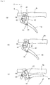
- a releasing lever 62 integrally including a restraining member and a releasing mechanism is disposed.
- the releasing lever 62 is substantially V-shaped in a side view.
- a first end of the releasing lever 62 has a pivoting hole 62a allowing the releasing lever 62 to be pivotally supported, via a pivotal support shaft 63, on an attachment member 21 fixed to the operation handle 8.
- a torsion spring 66 is externally fitted.
- the releasing lever 62 is biased counterclockwise in FIG. 11(a) , i.e., in a direction of locking.
- the releasing lever 62 has an intermediate portion in which a guide hole 64 serving as a restraining member is opened.
- a lock pin 65 protruding laterally from a front portion of a side surface of the forward-reverse switching lever 14 is inserted.
- the guide hole 64 is substantially inverse V-shaped in a side view. A front lower end of the guide hole 64 defines a lock position 64a, a center top end in a front-rear direction of the guide hole 64 defines a release position 64b, and a rear lower end of the guide hole 64 defines an acting position 64c.
- a second end of the releasing lever 62 extends upward to be within operator's reach with his/her thumb when the operator holds the grip 8a.
- a tip of the second end of the releasing lever 62 is formed as a pressing portion 62b.
- a forward-reverse switching lever 14 is attached to a grip 8a of one of left and right sides of an operation handle 8.
- a releasing lever 72 is disposed in the vicinity of the grip 8a of the one of the left and right sides of the operation handle 8.
- the releasing lever 72 is made of a bar-shaped member bent into a substantial C-shape in a rear view.
- the releasing lever 72 has a first side (lower side) that is horizontal and is pivotally supported on a front portion of a forward-reverse switching lever 14.
- a torsion spring 73 is externally fitted.
- the torsion spring 73 biases the releasing lever 72 so that the releasing lever 72 is turned rearward.
- the releasing lever 72 has a second side (upper side) that is horizontal and is inserted into a guide hole 74 opened in an attachment member 21.
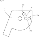
- the guide hole 74 which is formed in the attachment member 21, serves as a restraining member. As illustrated in FIG. 14 , the guide hole 74 has a horizontal portion extending in a front-rear direction and an arc-shaped portion extending upward from a front end of the horizontal portion. The guide hole 74 has turning ends defining a lock position 74a, a release position 74b, and an acting position 74c, respectively.
- the first end of the releasing lever 72 pivotally supported on the forward-reverse switching lever 14 is at the lock position 74a of the guide hole 74, as illustrated in FIG. 13(a) .
- the forward-reverse switching lever 14 cannot be turned, since the upper horizontal portion of the releasing lever 72 located at the lock position 74a of the guide hole 74 cannot move upward.
- the upper portion of the releasing lever 72 is brought to the release position 74b, as illustrated in FIG. 13(b) .
- a forward-reverse switching lever 14 is attached to a grip 8a of one of left and right sides of an operation handle 8. In the vicinity of the grip 8a of the one of the left and right sides of the operation handle 8, a releasing lever 82 is disposed.
- the releasing lever 82 is substantially C-shaped in a plan view.
- the releasing lever 82 has a first end (front end) supported on a support shaft 81 in such a manner that the first end can be turned in a left-right direction.
- the releasing lever 82 has an intermediate portion detouring a pivotal support shaft 22 to reach a rear portion of an attachment member 21.
- the pivotal support shaft 22 pivotally supports the forward-reverse switching lever 14.
- the attachment member 21 has, in its rear portion, a cutout 21a serving as a restraining member. Into the cutout 21a, the intermediate portion of the releasing lever 82 is inserted.
- the releasing lever 82 has a second end (rear end) extending toward a location lateral to the forward-reverse switching lever 14 so as to be within operator's reach with his/her thumb when the operator holds the grip 8a with his/her right hand.
- a tip of the second end of the releasing lever 82 is formed as a pressing portion 82a.
- the support shaft 81 protrudes downward from a support member 80, which is disposed in front of the attachment member 21.
- the support shaft 81 supports a front portion of the releasing lever 82 such that the releasing lever 82 can be turned in a left-right direction.
- a torsion spring 83 is externally fitted to the support shaft 81.
- the torsion spring 83 biases the releasing lever 82 so that the releasing lever 82 is turned toward the attachment member 21 (i.e., clockwise in a plan view).
- the intermediate portion of the releasing lever 82 is fitted to the cutout 21a. Consequently, the releasing lever 82 comes on a rotation locus of the base of the forward-reverse switching lever 14, thereby restraining turning of the forward-reverse switching lever 14.
- the operator cannot turn the forward-reverse switching lever 14 for selecting reverse traveling unless the operator pushes the releasing lever 42, 62, 72, or 82.
- the operator pushes the releasing lever 42, 62, 72, or 82.
- the forward-reverse switching operation device 20 for the cultivator 1, which is the agriculture machine includes the forward-reverse switching lever 14 provided to one of the left and right sides of the operation handle 8, the forward-reverse switching lever 14 being used to cause the forward-reverse switching device 28 to switch between forward traveling and reverse traveling, wherein the erroneous operation prevention mechanism 40 is provided to the one of the left and right sides of the operation handle 8, the erroneous operation prevention mechanism 40 is configured to restrain the forward-reverse switching lever 14 from being shifted to a position for reverse traveling when the forward-reverse switching lever is operated, the erroneous operation prevention mechanism 40 includes the restraining member 41 configured to restrain turning of the forward-reverse switching lever and the releasing lever 42, 62, 72, or 82 used to release the restraining, and the forward-reverse switching lever 14 and the releasing lever 42, 62, 72, or 82 are operable simultaneously by a single hand of an operator.
- a direction in which the forward-reverse switching lever 14 is operated to select reverse traveling and a direction in which the releasing lever 42, 62, 72, or 82 is operated to release the restraining are different from each other.
- the operator may operate the releasing lever 42, 62, 72, or 82 downward, forward, or laterally, and thereafter the operator may grip the forward-reverse switching lever 14 upward to perform the switchover.
- the operator can operate these levers in this manner while holding the operation handle 8 with his/her single hand.
- the forward-reverse switching lever 14 and the releasing lever 42, 62, 72, or 82 are operated in the direction of gripping. Therefore, the operator can easily apply force. Consequently, an erroneous operation hardly occurs.
- the present invention is applicable to walking-type cultivators used for works such as tilling and ridging in paddy fields and dry fields.
Landscapes
- Life Sciences & Earth Sciences (AREA)
- Engineering & Computer Science (AREA)
- Mechanical Engineering (AREA)
- Soil Sciences (AREA)
- Environmental Sciences (AREA)
- Power Engineering (AREA)
- Mechanical Control Devices (AREA)
- Arrangement Or Mounting Of Control Devices For Change-Speed Gearing (AREA)
- Soil Working Implements (AREA)
Abstract
Description
- The present invention relates to a technique for preventing an erroneous operation caused with a forward-reverse switching lever used to switch between forward traveling and reverse traveling of a cultivator that is an agriculture machine and for reducing a load to operate the forward-reverse switching lever.
- According to a conventionally-known technique (see, e.g., Patent Literature 1 (hereinafter, referred to as PTL 1)), a cultivator includes a handle, a forward-reverse switching lever and an accelerator lever disposed in a rear portion of the handle, and an interlocking mechanism configured to simultaneously cause switchover from forward traveling to reverse traveling and turning of the accelerator lever to a low-speed side in response to an operation of the forward-reverse switching lever. Consequently, an operator can execute the switchover from forward traveling to reverse traveling without releasing his/her hand from the handle. In addition, this technique reduces the number of revolutions of an engine at the time of the switchover to reverse traveling, thereby preventing sudden reverse traveling of the cultivator. This makes it possible to prevent the accelerator lever from being left unreturned to the low-speed side at the time of the switchover to reverse traveling.
- Another conventionally-known technique (see, e.g., Patent Literature 2 (hereinafter, referred to as PTL 2)) employs restraining means configured to restrict a shift lever from being shifted to a position for reverse traveling in a state where a clutch lever is at an engagement position.
-
- PTL 1: Japanese Utility Model Registration No.
2605471 (1994 - PTL 2: Japanese Patent Application Laid-Open No.
2009-220686 - According to the technique disclosed in PTL 1, however, the cultivator travels in a reverse direction in response to an operation of the forward-reverse switching lever. Therefore, when an operator unintentionally operates the forward-reverse switching lever, the cultivator may travel in a reverse direction against the operator's intention. Meanwhile, the technique disclosed in
PTL 2 may hardly permit an unintentional operation for reverse traveling. However, according to this technique, a member for selecting reverse traveling is not provided to the handle. The operation for reverse traveling is performed with the shift lever, which protrudes from a transmission case. Thus, this technique involves poor operability. - In view of the circumstances described above, some aspects of the present invention are to provide a forward-reverse switching operation device including an erroneous operation prevention mechanism provided near a forward-reverse switching lever, the erroneous operation prevention mechanism being configured to restrain the forward-reverse switching lever from being operated to select reverse traveling, the erroneous operation prevention mechanism including a restraining member and a releasing lever that are operable substantially simultaneously by a single hand of an operator. Such a forward-reverse switching operation device is capable of preventing an erroneous operation that may otherwise be caused with a forward-reverse switching lever, and provides good operability.
- According to the traditional technique described above, the position holding of the accelerator lever needs to be released in an initial range of an operation stroke of the forward-reverse switching lever, and thereafter switchover to reverse traveling needs to be performed. In order to achieve this, a long hole is provided to an operation arm. However, such a configuration requires an operator to grip the forward-reverse switching lever against a biasing force of a spring from a beginning to an end of a stroke of an interlocking body, thereby resulting in a gradually increased load to operate the forward-reverse switching lever. Thus, in order to select reverse traveling, the operator needs to keep griping the forward-reverse switching lever with a large load. In addition, actual mass-produced machines include an operation arm having a rotary base made of a spring steel. When the position holding of the accelerator lever is released, the spring steel is bent alone, and the interlocking body does not stroke. Such a configuration requires precise adjustment in assembling, which takes time. Moreover, this configuration involves poor durability, since the spring steel is bent in response to an operation of the forward-reverse switching lever. In addition, the problem of the large load to grip the forward-reverse switching lever remains unsolved.
- In view of these, some aspects of the present invention are to provide an interlocking mechanism which makes it possible to perform releasing of the position holding of the accelerator lever and switchover between forward traveling and reverse traveling with single operation means that is the forward-reverse switching lever at different timings. Such an interlocking mechanism also makes it possible to reduce the operational load.
- Some aspects of the present invention have been made in order to solve the above problems. The following describes means for solving these problems.
- A first aspect of the present invention provides a forward-reverse switching operation device for an agriculture machine, including a forward-reverse switching lever provided to one of left and right sides of an operation handle, the forward-reverse switching lever being used to cause a forward-reverse switching device to switch between forward traveling and reverse traveling, wherein an erroneous operation prevention mechanism is provided to the one of the left and right sides of the operation handle, the erroneous operation prevention mechanism being configured to restrain the forward-reverse switching lever from being shifted to a position for reverse traveling when the forward-reverse switching lever is operated, the erroneous operation prevention mechanism includes a restraining member configured to restrain turning of the forward-reverse switching lever and a releasing lever used to release the restraining, and the forward-reverse switching lever and the releasing lever are operable simultaneously by a single hand of an operator.
- The first aspect of the present invention may be configured such that a direction in which the forward-reverse switching lever is operated to select reverse traveling and a direction in which the releasing lever is operated to release the restraining are different from each other.
- The first aspect of the present invention may be configured such that a restraining action of the erroneous operation prevention mechanism is achieved between the forward-reverse switching lever and the restraining member, the restraining action being performed by a cable terminal of a wire via which the forward-reverse switching lever and the forward-reverse switching device are linked to each other.
- A second aspect of the present invention provides a forward-reverse switching operation device for an agriculture machine, including a forward-reverse switching lever provided to an operation handle, the forward-reverse switching lever being linked to a forward-reverse switching device and being used to switch between forward traveling and reverse traveling, wherein an accelerator lever is disposed near the forward-reverse switching lever, the accelerator lever being used to adjust the number of revolutions of an engine, an interlocking mechanism is interposed between the forward-reverse switching lever and the accelerator lever, the interlocking mechanism being configured to cause the accelerator lever to move to a low-speed side in conjunction with an operation of the forward-reverse switching lever for selecting reverse traveling, and the interlocking mechanism has an interlocking range in which the accelerator lever operates in conjunction with an operation of the forward-reverse switching lever and a non-interlocking range in which the forward-reverse switching device is actuated by an operation of the forward-reverse switching lever but the accelerator lever does not operate in conjunction with the operation of the forward-reverse switching lever.
- The second aspect of the present invention may be configured such that the interlocking range and the non-interlocking range are defined in a cam mechanism in an operation arm included in the interlocking mechanism interposed between the forward-reverse switching lever and the accelerator lever.
- The second aspect of the present invention may be configured such that the cam mechanism is made of a long hole, which guides a fastening member inserted thereinto, the fastening member being provided at an end of a connecting member via which the forward-reverse switching device and the forward-reverse switching lever are linked to each other.
- Some aspects of the present invention provide effects described below.
- Even when an operator grips and operates the forward-reverse switching lever carelessly, the forward-reverse switching lever would not be turned to start reverse traveling, unless the releasing lever is operated simultaneously with the operation of the forward-reverse switching lever. This configuration can prevent an erroneous operation. In addition, the operator can operate the forward-reverse switching lever and the releasing lever with his/her single hand. This configuration can maintain good operability.
- According to the interlocking mechanism of the traditional technique, the entire stroke of the forward-reverse switching lever is linked to a shifting operation of the accelerator lever to the low-speed side, and therefore it has been troublesome to adjust an acting position for causing the accelerator lever to move toward the low-speed side. Meanwhile, according to the aspects of the present invention, it is only necessary to align an end of the interlocking range in the cam mechanism with the interlocking mechanism. Thus, it is possible to easily perform the adjustment in the assembling. In addition, a force to operate the accelerator lever is not necessary in the non-interlocking range. Thus, it is possible to reduce the operational load.
-
- [
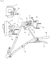
FIG. 1 ] A side view of an entire cultivator including a forward-reverse switching operation device according to an aspect of the present invention. - [
FIG. 2 ] A perspective view of an interlocking mechanism of a forward-reverse switching lever provided to an operation handle. - [
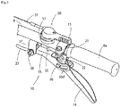
FIG. 3 ] A perspective view of the forward-reverse switching lever. - [
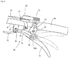
FIG. 4 ] A side view of the forward-reverse switching lever. - [
FIG. 5 ] A perspective view of an operation arm. - [
FIG. 6 ] A side view illustrating how the operation arm and an accelerator lever operate in conjunction with each other. - [
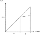
FIG. 7 ] A view illustrating a relation between a stroke and a load of the forward-reverse switching lever. - [
FIG. 8 ] A perspective view of the forward-reverse switching lever and an erroneous operation prevention mechanism. - [
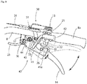
FIG. 9 ] A side view of the forward-reverse switching lever and the erroneous operation prevention mechanism. - [
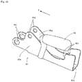
FIG. 10 ] A perspective view of a restraining member and a releasing lever. - [
FIG. 11 ] A view illustrating how an erroneous operation prevention mechanism according to a second embodiment is operated. - [
FIG. 12 ] A side view of a releasing lever of the erroneous operation prevention mechanism according to the second embodiment. - [
FIG. 13 ] A view illustrating how an erroneous operation prevention mechanism according to a third embodiment is operated. - [
FIG. 14 ] A side view of an attachment member of the erroneous operation prevention mechanism according to the third embodiment. - [
FIG. 15 ] A plan view and a side view illustrating a restraining member according to a fourth embodiment and how the restraining member is operated. - The following description first deals with an overall configuration of a cultivator 1 that is an agriculture machine. The description below is given with "direction F" being defined as the front.
- Referring to
FIG. 1 , the cultivator 1 includes amachine body frame 2, anengine 3, atransmission case 4, and atransfer case 5. Theengine 3 is mounted on themachine body frame 2. Thetransmission case 4 is disposed in a standing manner at a location that is behind theengine 3 and in the center in a left-right direction (i.e., laterally) of themachine body frame 2. Thetransfer case 5 is disposed between an upper portion of thetransmission case 4 and theengine 3, thereby enabling power transmission therebetween. Below thetransmission case 4, a tillingshaft 6 is provided so as to extend laterally and horizontally. Namely, the tillingshaft 6 is disposed perpendicularly to direction F, which is a traveling direction. The tillingshaft 6 is provided with tillingtines 7. The tillingtines 7 are fixed to the tillingshaft 6 such that the tillingtines 7 are arranged radially at predetermined intervals. The tillingshaft 6 and the tillingtines 7 constitute a tillingdevice 10. Rotation of the tillingshaft 6 also causes the cultivator 1 to travel. - Above the
engine 3, a fuel tank is disposed. Theengine 3 and the fuel tank are covered with an engine hood 9. Themachine body frame 2 has a rear portion to which aresistance bar 11 is attached such that a vertical height of theresistance bar 11 is adjustable. Themachine body frame 2 has a front end to which abumper 12 is attached. - An upper portion of the
transmission case 4, which is located in a rear portion of the machine body, is fixed to a base of anoperation handle 8. The operation handle 8 protrudes obliquely upward toward the rear, and is A-shaped in a plan view. As illustrated inFIG. 2 , the operation handle 8 has, in its rear portion, grips 8a to be gripped by an operator. In the vicinity of thegrip 8a disposed on the left side with respect to the traveling direction, a travelingclutch lever 13 is disposed. The travelingclutch lever 13 is connected, via a wire, to a belt-tension type traveling clutch accommodated in thetransfer case 5. When the operator grips the travelingclutch lever 13, the traveling clutch is engaged. Accordingly, driving power from theengine 3 is transferred to the tillingshaft 6, thereby allowing the cultivator 1 to travel and perform tilling. When the operator releases the travelingclutch lever 13, the traveling clutch is disengaged. Accordingly, the driving power is shut off, thereby stops the traveling and the tilling of the cultivator 1. Thus, for example, in a case of overturning of the cultivator 1 during work, the operator can cause the traveling clutch to be disengaged to stop the cultivator 1 merely by releasing the hand from the travelingclutch lever 13. This can prevent the clutch from being engaged against the operator's intention, for example. - In the vicinity of the
grip 8a disposed on the right side of theoperation handle 8, a forward-reverseswitching operation device 20, anaccelerator lever 15, and anemergency stop button 16 are disposed. The forward-reverseswitching operation device 20 includes a forward-reverse switching lever 14, an interlockingmechanism 30, and an erroneousoperation prevention mechanism 40. Theemergency stop button 16 is disposed on a connectingrod 17 via which the left and right sides of the operation handle 8 are connected to each other. Pressing theemergency stop button 16 can stop theengine 3. - As illustrated in
FIGs. 2 to 4 , a front upper portion of the forward-reverse switching lever 14 is vertically turnably supported, via apivotal support shaft 22, on anattachment member 21 fixed to a front portion of thegrip 8a of theoperation handle 8. This allows the operator to operate the forward-reverse switching lever 14 while gripping the forward-reverse switching lever 14 together with thegrip 8a. A front lower portion of the forward-reverse switching lever 14 is connected, via awire 23 that is a connecting member, to aswitching arm 24 provided to thetransmission case 4. A rear end of thewire 23 is fixed to a pin-shapedcable terminal 26 that is a fastening member. Thecable terminal 26 is disposed perpendicularly to a longitudinal direction (i.e., disposed laterally). Thecable terminal 26 is inserted into and fastened at a pin hole opened laterally in the front lower portion of the forward-reverse switching lever 14. - As illustrated in
FIG. 2 , one end of the switchingarm 24 is pivotally supported on thetransmission case 4, and the other end of the switchingarm 24 is coupled to thewire 23 and a spring 27. The spring 27 biases the switchingarm 24 in a direction for selecting forward traveling. A protrusion of the switchingarm 24 is connected to one end of ashifter shaft 25, thereby enabling the switchingarm 24 and theshifter shaft 25 to operate in conjunction with each other. Theshifter shaft 25 is configured to operate the forward-reverse switching clutch accommodated in thetransmission case 4. The forward-reverse switching clutch includes a shifter fixed to theshifter shaft 25. The shifter is designed to slide to change an engagement mode of an engagement claw to cause the tillingshaft 6 to rotate in a forward or reverse direction. The forward-reverse switching clutch is normally kept at forward traveling side by the biasing force of the spring 27. Gripping and turning the forward-reverse switching lever 14 pulls thewire 23 against the force of the spring 27 to turn theswitching arm 24. This causes theshifter shaft 25 to slide, thereby shifting the forward-reverse switching clutch to a position for reverse traveling. A forward-reverse switching device 28 is configured as described above. In the above configuration, the forward-reverse switching clutch includes the engagement claw that is to be engaged. However, the present invention is not limited to this. Alternatively, the forward-reverse switching clutch may include a gear that is to be engaged or an electromagnetic clutch that is to be turned on and off. - As illustrated in
FIG. 2 , theaccelerator lever 15 is connected to acontrol lever 32 of theengine 3 via awire 31. Thecontrol lever 32 is configured to change the number of revolutions of the engine 3 (engine speed) to adjust amounts of fuel and intake air. For example, in a case where theengine 3 is a gasoline engine, thecontrol lever 32 changes opening of a throttle valve. - The
accelerator lever 15 is attached to the operation handle 8 via an operated-position holding/releasingmechanism 50. Theaccelerator lever 15 is configured to operate in conjunction with the forward-reverse switching lever 14 via theinterlocking mechanism 30. As illustrated inFIG. 6 , the operated-position holding/releasingmechanism 50 includes a fixingmember 51, alever base 53, a pressingmember 54, a releasingshaft 55, apressing spring 56, and alever spring 57, for example. The fixingmember 51 is fixed to theoperation handle 8. Thelever base 53 is externally fitted onto the fixingmember 51 via afriction plate 52 in such a manner as to allow thelever base 53 to turn. The pressingmember 54 has a cylindrical shape, and is configured to press thelever base 53 downward. The releasingshaft 55 is slidably inserted into axial centers of the fixingmember 51, thelever base 53, and the pressingmember 54. Thepressing spring 56 is configured to bias the releasingshaft 55, the pressingmember 54, and thelever base 53 downward with respect to the fixingmember 51. Thelever spring 57 is interposed between thelever base 53 and the pressingmember 54, and is configured to bias theaccelerator lever 15 so that theaccelerator lever 15 is turned toward a low-speed side. - The fixing
member 51 has a cylindrical shape having ashaft hole 51a in its center. The releasingshaft 55 penetrates through theshaft hole 51a in a top-bottom direction (i.e., vertically). Theshaft hole 51a internally includes, in its lower portion, thepressing spring 56. Thepressing spring 56 is disposed between an inner surface of theshaft hole 51a and the releasingshaft 55. An upper end of thepressing spring 56 is in contact with an upper portion of the inner surface of theshaft hole 51a, and a lower end of thepressing spring 56 is in contact with a step of the releasingshaft 55 via awasher 59. The releasingshaft 55 is biased, by thepressing spring 56, downward with respect to the fixingmember 51. Thelever base 53 is externally fitted onto anouter periphery 51b of the fixingmember 51 via thefriction plate 52. Thelever base 53 has a center hole into which the pressingmember 54 is attached. With this configuration, when the releasingshaft 55 is biased downward by thepressing spring 56, thelever base 53 is pressed downward via awasher 58 and the pressingmember 54, so that friction forces are generated between a lower surface of thelever base 53, an upper surface of theouter periphery 51b of the fixingmember 51, and thefriction plate 52. Thanks to these friction forces, theaccelerator lever 15 having been turned to a desired position is held at the position. - The
lever base 53 has a cylindrical shape whose through hole has an innerperipheral step 53a. On the innerperipheral step 53a, the pressingmember 54 having a cylindrical shape is rotatably accommodated. The shaft hole of the pressingmember 54 and an outer periphery of ashaft 51c, which is in an upper portion of the fixingmember 51, are spline-fitted to each other. Thus, the pressingmember 54 is fitted to the fixingmember 51 in such a manner that the pressingmember 54 can vertically slide with respect to the fixingmember 51 but cannot rotate. Thelever spring 57 is fastened between an upper portion of the pressingmember 54 and an inner periphery of thelever base 53. Thelever spring 57 biases theaccelerator lever 15 so that theaccelerator lever 15 is turned toward the low-speed side. In addition, the releasingshaft 55 has a lower portion penetrating through theoperation handle 8 and protruding from the operation handle 8 downward. The lower portion of the releasingshaft 55 can reach a position at which the lower portion of the releasingshaft 55 comes in contact with an upper surface of an operation arm 35 (described later). - With such a configuration, turning the
accelerator lever 15 toward a high-speed side causes thepressing spring 56 to exert a spring force to bias thelever base 53 downward, so that theaccelerator lever 15 is held at a desired turned position by friction resistance between thelever base 53, thefriction plate 52, and the fixingmember 51. The pressing spring force of thepressing spring 56 is set to be greater than a spring force of thelever spring 57 that is returning and a force of thecontrol lever 32 that is returning to the low-speed side. Thus, theaccelerator lever 15 would not be returned to the low-speed side. - Then, in a state where the
accelerator lever 15 has been turned to the high-speed side, gripping and turning the forward-reverse switching lever 14 causes theoperation arm 35 to be turned upward, so that the releasingshaft 55 is raised. This releases the pressing force of thelever base 53 with respect to the fixingmember 51, thereby reducing the friction resistance for the position holding. Accordingly, theaccelerator lever 15 is turned toward the low-speed side by the biasing force of thelever spring 57, thereby causing theengine 3 to run at a low engine speed. Further turning the forward-reverse switching lever 14 results in switchover of the forward-reverse switching device 28, so that the machine body travels in a reverse direction. - Next, the following describes the interlocking
mechanism 30 with reference toFIGs. 2 to 6 . - In conjunction with the turning of the forward-
reverse switching lever 14, the interlockingmechanism 30 releases theaccelerator lever 15 having been turned to the high-speed side and causes theaccelerator lever 15 to be turned toward the low-speed side. The interlockingmechanism 30 is interposed between the forward-reverse switching lever 14 and the releasingshaft 55. The interlockingmechanism 30 is constituted by theoperation arm 35. - As illustrated in
FIG. 5 , theoperation arm 35 is made of a plate bent into a substantially inverse U-shape in a front view. Theoperation arm 35 includes left andright side plates 35a and a connectingplate 35b via which front upper portions of the left andright side plates 35a are connected to each other. Front ends of theside plates 35a have pivotingfulcrum holes 35c, and rear portions of theside plates 35a have arc-shapedlong holes 35d which are long in a front-rear direction and by which a cam is defined. The connectingplate 35b is positioned below the operated-position holding/releasingmechanism 50. The connectingplate 35b is a contact surface with which the lower end of the releasingshaft 55 can come in contact. - Into the pivoting
fulcrum holes 35c, apivotal support shaft 36 is inserted. Thus, a front portion of theoperation arm 35 is pivotally supported, via thepivotal support shaft 36, on asupport 37 fixed at a location that is forward of the fixingmember 51 and downward of thehandle 8. Thesupport 37 protrudes downward from thehandle 8. - Into the
long holes 35d, thecable terminal 26 is inserted. In conjunction with turning of the forward-reverse switching lever 14, thecable terminal 26 slides inside thelong holes 35d. The sliding of thecable terminal 26 causes theoperation arm 35 to be turned up or down. Thanks to the shapes of thelong holes 35d defining the cam, a force to turn the forward-reverse switching lever 14 (i.e., a force to grip the forward-reverse switching lever 14) is smaller than that of the traditional techniques. - The
long holes 35d are formed as a cam profile, which slidingly guides thecable terminal 26 inserted into thelong holes 35d. As illustrated inFIGs. 4 and6 , the cam profile has an interlocking range α and a non-interlocking range β. In the interlocking range α, theaccelerator lever 15 operates in conjunction with an operation of the forward-reverse switching lever 14. In the non-interlocking range β, the forward-reverse switching device 28 is actuated by an operation of the forward-reverse switching lever 14 but theaccelerator lever 15 does not operate in conjunction with the operation of the forward-reverse switching lever 14. - Specifically, each of the
long holes 35d has a front portion that is a front long hole 35d1. The front long hole 35d1 extends obliquely linearly such that a distance between the front long hole 35dl and thepivotal support shaft 22 increases as it gets closer to the rear side. Inside the front long holes 35d1 formed as above, thecable terminal 26 slides along circular loci concentric about thepivotal support shaft 22. A range in which thecable terminal 26 slides inside the front long holes 35dl in this manner corresponds to the interlocking range α for causing theoperation arm 35 to be turned up or down. A difference in stroke of the forward-reverse switching lever 14 before and after turning of the forward-reverse switching lever 14, that is, a radial difference of the forward-reverse switching lever 14 corresponds to a length required to raise the releasingshaft 55 to release the holding of the operational position of theaccelerator lever 15. - Meanwhile, each of the
long holes 35d has a rear portion that is a rear long hole 35d2, which follows the interlocking range α and in which theoperation arm 35 is not turned. The rear long hole 35d2 is formed such that a distance between the rear long hole 35d2 and thepivotal support shaft 22 is constant, i.e., such that the rear long hole 35d2 is shaped in an arc having a constant radius about thepivotal support shaft 22, in order not to raise the releasingshaft 55 even when the forward-reverse switching lever 14 is operated, in other words, in order not to turn theoperation arm 35 even when the forward-reverse switching lever 14 is further turned. - With this configuration, when the operator turns (grips) the forward-
reverse switching lever 14 during a tilling work with the cultivator 1 moving forward, thewire 23 is pulled and theoperation arm 35 is turned upward via thecable terminal 26 while thecable terminal 26 is in the interlocking range α. The upward turning of theoperation arm 35 raises the releasingshaft 55. At a time when the releasingshaft 55 reaches a position at which friction held between the fixingmember 51 and thelever base 53 is released, theaccelerator lever 15 is returned to the low-speed position by a biasing force of thelever spring 57. A force to grip the forward-reverse switching lever 14 at this time increases gradually, as shown by a solid line inFIG. 7 . - While the
cable terminal 26 is in the non-interlocking range β following the interlocking range α, theoperation arm 35 would not be turned even when the forward-reverse switching lever 14 is turned. Rather, thecable terminal 26 is further pulled, thereby the switchingarm 24 is turned. This causes switchover of the forward-reverse switching device 28 from forward traveling to reverse traveling. At this time, it is no longer necessary to push the releasingshaft 55 upward, and therefore an increase in operational force to grip the forward-reverse switching lever 14 decreases, as illustrated inFIG. 7 . At this time, however, a force to pull thewire 23 against the force of the spring 27 and a force to hold the releasingshaft 55 at the position against thepressing spring 56 are necessary, and therefore the operational force slightly increases. A broken line inFIG. 7 indicates a relation between a stroke of a forward-reverse switching lever 14 and a force (load) to operate the forward-reverse switching lever 14 in the configuration of the traditional technique employing an operation arm made of a spring steel. According to such a traditional configuration, the operational force (load) over an entire stroke to turn the forward-reverse switching lever 14 to bend the spring steel is significantly larger than that in the configuration of the present embodiment employing theoperation arm 35 described above. - As described above, a forward-reverse
switching operation device 20 for an agriculture machine includes the forward-reverse switching lever 14 provided to theoperation handle 8, the forward-reverse switching lever 14 being linked to the forward-reverse switching device 28 and being used to switch between forward traveling and reverse traveling. Theaccelerator lever 15 is disposed near the forward-reverse switching lever 14, theaccelerator lever 15 being used to adjust the number of revolutions of theengine 3. The interlockingmechanism 30 is interposed between the forward-reverse switching lever 14 and theaccelerator lever 15, the interlockingmechanism 30 being configured to cause theaccelerator lever 15 to move to the low-speed side in conjunction with an operation of the forward-reverse switching lever 14 for selecting reverse traveling. The interlockingmechanism 30 has the interlocking range α, in which theaccelerator lever 15 operates in conjunction with an operation of the forward-reverse switching lever 14, and the non-interlocking range β, in which the forward-reverse switching device 28 is actuated by an operation of the forward-reverse switching lever 14 but theaccelerator lever 15 does not operate in conjunction with the operation of the forward-reverse switching lever 14. With this configuration, merely by operating the forward-reverse switching lever 14 alone, it is possible to cause theaccelerator lever 15 to be turned to the low-speed side by the interlockingmechanism 30, and thereafter to perform switchover from forward traveling to reverse traveling. In addition, a force to operate the forward-reverse switching lever 14 at that time can be significantly reduced, as compared to that of the traditional techniques. - The interlocking range α and the non-interlocking range β are defined in the cam mechanism in the
operation arm 35 included in theinterlocking mechanism 30, which is interposed between the forward-reverse switching lever 14 and theaccelerator lever 15. Thus, it is possible to easily redefine a partition between the interlocking range α and the non-interlocking range β by changing the cam profile. In order to manufacture anoperation arm 35 from a spring steel, a quenching process is required. Theoperation arm 35 manufactured in this manner may be unstable in shape and have great variation in acting position. Thus, positioning adjustment of such anoperation arm 35 has been troublesome. Meanwhile, the embodiment of the present invention does not use the spring steel, but defines the interlocking range by the cam. Thus, positioning adjustment of theoperation arm 35 according to the embodiment of the present invention is easy. - The cam mechanism is made of the
long holes 35d, which guide thecable terminal 26 inserted thereinto. Thecable terminal 26 is the fastening member provided at an end of thewire 23. Thewire 23 is the connecting member via which the forward-reverse switching device 28 and the forward-reverse switching lever 14 are linked to each other. With this configuration, in order to define the positions of the forward-reverse switching lever 14 and theoperation arm 35, it is only necessary to place thecable terminal 26 at ends of thelong holes 35d. Thus, positioning of theoperation arm 35 is easy. - Next, the following describes the erroneous
operation prevention mechanism 40 with reference toFIGs. 2 and8 to 10 . - The erroneous
operation prevention mechanism 40 includes a restrainingmember 41, a releasinglever 42, astopper pin 43, and atorsion spring 44, for example. The restrainingmember 41 is configured to restrain turning of the forward-reverse switching lever 14. The releasinglever 42 is used to release the restraining. The erroneousoperation prevention mechanism 40 is disposed on the one of the left and right sides of the operation handle 8 on which the forward-reverse switching lever 14 is disposed (i.e., on thegrip 8a on the right side). The restrainingmember 41 is disposed near the forward-reverse switching lever 14, and the restrainingmember 41 covers theoperation arm 35 from below. - The restraining
member 41 is made of a plate bent into a substantial U-shape in a rear view. The restrainingmember 41 includes left andright side plates 41a and abottom plate 41b via which theside plates 41a are connected to each other. A distance between theside plates 41a is greater than a width of theoperation arm 35. Consequently, the restrainingmember 41 can externally cover theoperation arm 35 from below, which enables compact arrangement. Theside plates 41a have pivotingfulcrum holes 41c in their front portions. Thepivotal support shaft 36 is inserted into the pivotingfulcrum holes 41c and the pivotingfulcrum holes 35c of theoperation arm 35. Thus, the restrainingmember 41 is supported pivotally about thepivotal support shaft 36. - The
side plates 41a havepin holes 41d at locations rearward and upward of the pivotingfulcrum holes 41c, respectively. After the restrainingmember 41 is fitted to theoperation arm 35 and pivotally fixed by thepivotal support shaft 36, thestopper pin 43 is inserted into thepin holes 41d. This prevents the restrainingmember 41 from being turned downward exceeding a predetermined angle. - Rear upper portions of the
side plates 41a respectively have restrainingrecesses 41e that are opened forward and upward. In a state where the restrainingmember 41 is attached to theoperation arm 35, thecable terminal 26 is positioned in the restraining recesses 41e. - One of the
side plates 41a, which is on the inner side in a left-right direction of the machine body, is provided with the releasinglever 42 in its intermediate portion viewed in the front-rear direction. From the intermediate portion of the one of theside plates 41a, the releasinglever 42 protrudes rearward and upward. In the state where the restrainingmember 41 is attached to theoperation arm 35, a rear upper end of the releasinglever 42 is located in front of and lateral to thegrip 8a. Thus, the releasinglever 42 is disposed within a range in which the operator holding thegrip 8a with his/her right hand can operate the releasinglever 42 with his/her thumb. Namely, the restrainingmember 41 and the releasinglever 42 can be turned integrally. Alternatively, the restrainingmember 41 and the releasinglever 42 may be formed integrally as a single member. - In the state where the
pivotal support shaft 36 is attached to the restrainingmember 41 and theoperation arm 35, thetorsion spring 44 is externally attached to thepivotal support shaft 36. In this state, one end of thetorsion spring 44 is fastened to thesupport 37, and the other end of thetorsion spring 44 is fastened to the stopper pin 43 (or to the restraining member 41). Thetorsion spring 44 biases the restrainingmember 41 so that the restrainingmember 41 is turned upward. - With such a configuration, when the operator grips the forward-
reverse switching lever 14 to select reverse traveling during the work, thecable terminal 26 attempts to move rearward, but cannot be turned since it comes in contact with the restraining recesses 41e of the restrainingmember 41. Thus, the operation for selecting reverse traveling is restrained. When the operator pushes the releasinglever 42 downward with his/her thumb in this state, the restraining recesses 41e moves downward, thereby releasing the restraining. When the operator grips the forward-reverse switching lever 14 in this state, thecable terminal 26 can move rearward. Then, as described above, the interlockingmechanism 30 causes theaccelerator lever 15 to be turned to the low-speed side to reduce the number of revolutions of the engine, and then causes the forward-reverse switching device 28 to perform switchover to reverse traveling. - At the time when the releasing
lever 42 is pushed downward, thestopper pin 43 comes in contact with an upper surface (connectingplate 35b) of theoperation arm 35, thereby preventing the releasinglever 42 from being turned any further. From this, the operator can recognize, by his/her thumb, that the restraining has been released. In addition, from theaccelerator lever 15 having been turned to the low-speed side in conjunction with the turning of the forward-reverse switching lever 14 after the releasing of the lock (restraining), the operator can easily judge a timing to release his/her thumb. When the operator releases his/her thumb from the releasinglever 42, the restrainingmember 41 attempts to turn upward by a biasing force of thetorsion spring 44. However, the released state is maintained, since rear portions of upper surfaces of the restraining recesses 41e come into contact with a lower portion of thecable terminal 26. - When the operator releases his/her hand gripped the forward-
reverse switching lever 14 to end reverse traveling, the forward-reverse switching lever 14 is pulled by a biasing force of the spring 27 via thewire 23, so that the forward-reverse switching lever 14 is turned downward and thecable terminal 26 moves forward. Then, the forward-reverse switching lever 14 is brought to its lower end position, and the restrainingmember 41 is turned upward by a biasing force of thetorsion spring 44. Consequently, thecable terminal 26 is brought into the restraining recesses 41e, theoperation arm 35 is lowered, and the releasingshaft 55 is lowered to be returned to its original state. - As described above, the erroneous
operation prevention mechanism 40 is disposed near the forward-reverse switching lever 14, the erroneousoperation prevention mechanism 40 being configured to restrain the forward-reverse switching lever 14 from being shifted to a position for reverse traveling when the forward-reverse switching lever 14 is operated. The erroneousoperation prevention mechanism 40 includes: the restrainingmember 41 configured to restrain turning of the forward-reverse switching lever 14; and the releasinglever 42 used to release the restraining. With this configuration, an operation of the releasinglever 42 to release the restraining and an operation of the forward-reverse switching lever 14 to select reverse traveling can be performed by the operator substantially simultaneously with his/her single hand. Therefore, in order to select reverse traveling, the operator operates the forward-reverse switching lever 14 and the releasinglever 42 intentionally. Consequently, even if the operator grips the forward-reverse switching lever 14 carelessly, the agriculture machine would not travel in a reverse direction against the operator's intention. Thus, it is possible to reliably perform an operation for causing the agriculture machine to travel in a forward or reverse direction. In addition, since this configuration allows the operator to operate the releasinglever 42 and the forward-reverse switching lever 14 with his/her single hand, the operator can easily perform the operation to select reverse traveling, and does not have to change the hand to operate. - In addition, a direction in which the forward-
reverse switching lever 14 is operated is upward, whereas a direction in which the releasinglever 42 is operated is downward. Thus, the directions in which the forward-reverse switching lever 14 and the releasinglever 42 are operated are different from each other. Thanks to this configuration, an erroneous operation hardly occurs. Furthermore, while holding theoperation handle 8, the operator can easily operate these levers one by one consecutively (almost simultaneously). - Moreover, the restraining action of the erroneous
operation prevention mechanism 40 is achieved between the forward-reverse switching lever 14 and the restrainingmember 41, the restraining action being performed by thecable terminal 26 provided at the end of thewire 23 via which the forward-reverse switching lever 14 and the forward-reverse switching device 28 are linked to each other. Thus, thecable terminal 26 is restrained by the restrainingmember 41, and serves also as a restrained member. This configuration provides a restraining structure with a small number of parts and a simple configuration. - Next, the following describes an erroneous
operation prevention mechanism 40 according to a second embodiment with reference toFIGs. 11 and12 . - A forward-
reverse switching lever 14 is attached to agrip 8a of one of left and right sides of anoperation handle 8. In the vicinity of thegrip 8a of the one of the left and right sides of anoperation handle 8, a releasinglever 62 integrally including a restraining member and a releasing mechanism is disposed. As illustrated inFIG. 12 , the releasinglever 62 is substantially V-shaped in a side view. A first end of the releasinglever 62 has apivoting hole 62a allowing the releasinglever 62 to be pivotally supported, via apivotal support shaft 63, on anattachment member 21 fixed to theoperation handle 8. To thepivotal support shaft 63, atorsion spring 66 is externally fitted. One end of thetorsion spring 66 is fastened to the releasinglever 62, and the other end of thetorsion spring 66 is fastened to theattachment member 21. The releasinglever 62 is biased counterclockwise inFIG. 11(a) , i.e., in a direction of locking. - The releasing
lever 62 has an intermediate portion in which aguide hole 64 serving as a restraining member is opened. Into theguide hole 64, alock pin 65 protruding laterally from a front portion of a side surface of the forward-reverse switching lever 14 is inserted. Theguide hole 64 is substantially inverse V-shaped in a side view. A front lower end of theguide hole 64 defines alock position 64a, a center top end in a front-rear direction of theguide hole 64 defines arelease position 64b, and a rear lower end of theguide hole 64 defines an acting position 64c. - A second end of the releasing
lever 62 extends upward to be within operator's reach with his/her thumb when the operator holds thegrip 8a. A tip of the second end of the releasinglever 62 is formed as apressing portion 62b. - With such a configuration, during forward traveling, the
lock pin 65 protruding from the forward-reverse switching lever 14 is at thelock position 64a of theguide hole 64, as illustrated inFIG. 11(a) . In this state, even if the operator grips the forward-reverse switching lever 14 and tries to turn the forward-reverse switching lever 14, the forward-reverse switching lever 14 cannot be turned, since a long hole defined by thelock position 64a and therelease position 64b of theguide hole 64 is perpendicular to a direction in which thelock pin 65 moves when the forward-reverse switching lever 14 is turned. When the operator pushes thepressing part 62b downward with his/her thumb in this state to cause the releasinglever 62 to move downward, thelock pin 65 is brought to therelease position 64b (as illustrated inFIG. 11(b) ), thereby releasing the restraining. When the operator grips the forward-reverse switching lever 14 in this state, thelock pin 65 is turned to reach the acting position 64c, as illustrated inFIG. 11(c) . Consequently, awire 23 is pulled, and accordingly a forward-reverse switching device 28 performs switchover, thereby causing a cultivator 1 to travel in a reverse direction. - Next, the following describes an erroneous
operation prevention mechanism 40 according to a third embodiment with reference toFIGs. 13 and14 . - A forward-
reverse switching lever 14 is attached to agrip 8a of one of left and right sides of anoperation handle 8. In the vicinity of thegrip 8a of the one of the left and right sides of theoperation handle 8, a releasinglever 72 is disposed. The releasinglever 72 is made of a bar-shaped member bent into a substantial C-shape in a rear view. The releasinglever 72 has a first side (lower side) that is horizontal and is pivotally supported on a front portion of a forward-reverse switching lever 14. To the lower horizontal portion of the releasinglever 72, atorsion spring 73 is externally fitted. Thetorsion spring 73 biases the releasinglever 72 so that the releasinglever 72 is turned rearward. The releasinglever 72 has a second side (upper side) that is horizontal and is inserted into aguide hole 74 opened in anattachment member 21. - The
guide hole 74, which is formed in theattachment member 21, serves as a restraining member. As illustrated inFIG. 14 , theguide hole 74 has a horizontal portion extending in a front-rear direction and an arc-shaped portion extending upward from a front end of the horizontal portion. Theguide hole 74 has turning ends defining alock position 74a, arelease position 74b, and an actingposition 74c, respectively. - With such a configuration, during forward traveling, the first end of the releasing
lever 72 pivotally supported on the forward-reverse switching lever 14 is at thelock position 74a of theguide hole 74, as illustrated inFIG. 13(a) . Even if an operator grips the forward-reverse switching lever 14 in this state, the forward-reverse switching lever 14 cannot be turned, since the upper horizontal portion of the releasinglever 72 located at thelock position 74a of theguide hole 74 cannot move upward. When the operator pushes the releasinglever 72 forward with his/her thumb in this state, the upper portion of the releasinglever 72 is brought to therelease position 74b, as illustrated inFIG. 13(b) . When the operator grips the forward-reverse switching lever 14 in this state, the upper portion of the releasinglever 72 is caused to move along the arc-shaped portion of theguide hole 74 to reach the actingposition 74c, as illustrated inFIG. 13(c) . Consequently, awire 23 is pulled, and accordingly a forward-reverse switching device 28 performs switchover, thereby causing a cultivator 1 to travel in a reverse direction. - Next, the following describes an erroneous
operation prevention mechanism 40 according to a fourth embodiment with reference toFIG. 15 . - A forward-
reverse switching lever 14 is attached to agrip 8a of one of left and right sides of anoperation handle 8. In the vicinity of thegrip 8a of the one of the left and right sides of theoperation handle 8, a releasinglever 82 is disposed. The releasinglever 82 is substantially C-shaped in a plan view. The releasinglever 82 has a first end (front end) supported on asupport shaft 81 in such a manner that the first end can be turned in a left-right direction. The releasinglever 82 has an intermediate portion detouring apivotal support shaft 22 to reach a rear portion of anattachment member 21. Thepivotal support shaft 22 pivotally supports the forward-reverse switching lever 14. Theattachment member 21 has, in its rear portion, acutout 21a serving as a restraining member. Into thecutout 21a, the intermediate portion of the releasinglever 82 is inserted. The releasinglever 82 has a second end (rear end) extending toward a location lateral to the forward-reverse switching lever 14 so as to be within operator's reach with his/her thumb when the operator holds thegrip 8a with his/her right hand. A tip of the second end of the releasinglever 82 is formed as apressing portion 82a. - The
support shaft 81 protrudes downward from asupport member 80, which is disposed in front of theattachment member 21. Thesupport shaft 81 supports a front portion of the releasinglever 82 such that the releasinglever 82 can be turned in a left-right direction. To thesupport shaft 81, atorsion spring 83 is externally fitted. Thetorsion spring 83 biases the releasinglever 82 so that the releasinglever 82 is turned toward the attachment member 21 (i.e., clockwise in a plan view). Thus, the intermediate portion of the releasinglever 82 is fitted to thecutout 21a. Consequently, the releasinglever 82 comes on a rotation locus of the base of the forward-reverse switching lever 14, thereby restraining turning of the forward-reverse switching lever 14. - With such a configuration, during forward traveling, the intermediate portion of the releasing
lever 82 is fitted to thecutout 21a of theattachment member 21, and therefore the forward-reverse switching lever 14 cannot be turned. When the operator pushes the releasinglever 82 laterally with his/her thumb in this state, the intermediate portion of the releasinglever 82 leaves thecutout 21a, thereby releasing the restraining. Consequently, the operator can turn the releasinglever 82. Turning the releasinglever 82 pulls awire 23, and accordingly a forward-reverse switching device 28 performs switchover, thereby causing a cultivator 1 to travel in a reverse direction. InFIGs. 11 ,13 , and15 , some components, such as theaccelerator lever 15 and the interlockingmechanism 30, are not illustrated. - As described in the foregoing embodiments, the operator cannot turn the forward-
reverse switching lever 14 for selecting reverse traveling unless the operator pushes the releasinglever reverse switching lever 14. - As described above, the forward-reverse
switching operation device 20 for the cultivator 1, which is the agriculture machine, includes the forward-reverse switching lever 14 provided to one of the left and right sides of theoperation handle 8, the forward-reverse switching lever 14 being used to cause the forward-reverse switching device 28 to switch between forward traveling and reverse traveling, wherein the erroneousoperation prevention mechanism 40 is provided to the one of the left and right sides of theoperation handle 8, the erroneousoperation prevention mechanism 40 is configured to restrain the forward-reverse switching lever 14 from being shifted to a position for reverse traveling when the forward-reverse switching lever is operated, the erroneousoperation prevention mechanism 40 includes the restrainingmember 41 configured to restrain turning of the forward-reverse switching lever and the releasinglever reverse switching lever 14 and the releasinglever reverse switching lever 14 for selecting reverse traveling unless the operator pushes the releasinglever reverse switching lever 14. With this configuration, the operator can operate both of the releasinglever reverse switching lever 14 with his/her single hand. This eliminates the need to change the operator's hand to operate the releasinglever reverse switching lever 14 one by one. Consequently, the operator can operate these levers reliably without stopping the work. - In addition, a direction in which the forward-
reverse switching lever 14 is operated to select reverse traveling and a direction in which the releasinglever lever reverse switching lever 14 upward to perform the switchover. The operator can operate these levers in this manner while holding the operation handle 8 with his/her single hand. In addition, the forward-reverse switching lever 14 and the releasinglever - The present invention is applicable to walking-type cultivators used for works such as tilling and ridging in paddy fields and dry fields.
-
- α
- interlocking range
- β
- non-interlocking range
- 3
- engine
- 8
- operation handle
- 14
- forward-reverse switching lever
- 15
- accelerator lever
- 20
- forward-reverse switching operation device
- 23
- wire
- 26
- cable terminal
- 28
- forward-reverse switching device
- 30
- interlocking mechanism
- 35
- operation arm
- 40
- erroneous operation prevention mechanism
- 41
- restraining member
- 42
- releasing lever
Claims (6)
- A forward-reverse switching operation device for an agriculture machine, comprising:a forward-reverse switching lever provided to one of left and right sides of an operation handle, the forward-reverse switching lever being used to cause a forward-reverse switching device to switch between forward traveling and reverse traveling, whereinan erroneous operation prevention mechanism is provided to the one of the left and right sides of the operation handle, the erroneous operation prevention mechanism being configured to restrain the forward-reverse switching lever from being shifted to a position for reverse traveling when the forward-reverse switching lever is operated,the erroneous operation prevention mechanism includesa restraining member configured to restrain turning of the forward-reverse switching lever anda releasing lever used to release the restraining, andthe forward-reverse switching lever and the releasing lever are operable simultaneously by a single hand of an operator.
- The forward-reverse switching operation device according to claim 1, wherein a direction in which the forward-reverse switching lever is operated to select reverse traveling and a direction in which the releasing lever is operated to release the restraining are different from each other.
- The forward-reverse switching operation device according to claim 2, wherein a restraining action of the erroneous operation prevention mechanism is achieved between the forward-reverse switching lever and the restraining member, the restraining action being performed by a cable terminal of a wire via which the forward-reverse switching lever and the forward-reverse switching device are linked to each other.
- A forward-reverse switching operation device for an agriculture machine, comprising:a forward-reverse switching lever provided to an operation handle, the forward-reverse switching lever being linked to a forward-reverse switching device and being used to switch between forward traveling and reverse traveling, whereinan accelerator lever is disposed near the forward-reverse switching lever, the accelerator lever being used to adjust the number of revolutions of an engine,an interlocking mechanism is interposed between the forward-reverse switching lever and the accelerator lever, the interlocking mechanism being configured to cause the accelerator lever to move to a low-speed side in conjunction with an operation of the forward-reverse switching lever for selecting reverse traveling, andthe interlocking mechanism has an interlocking range in which the accelerator lever operates in conjunction with an operation of the forward-reverse switching lever and a non-interlocking range in which the forward-reverse switching device is actuated by an operation of the forward-reverse switching lever but the accelerator lever does not operate in conjunction with the operation of the forward-reverse switching lever.
- The forward-reverse switching operation device according to claim 4, wherein the interlocking range and the non-interlocking range are defined in a cam mechanism in an operation arm included in the interlocking mechanism interposed between the forward-reverse switching lever and the accelerator lever.
- The forward-reverse switching operation device according to claim 5, wherein the cam mechanism is made of a long hole, which guides a fastening member inserted thereinto, the fastening member being provided at an end of a connecting member via which the forward-reverse switching device and the forward-reverse switching lever are linked to each other.
Applications Claiming Priority (3)
| Application Number | Priority Date | Filing Date | Title |
|---|---|---|---|
| JP2016159327A JP6698470B2 (en) | 2016-08-15 | 2016-08-15 | Forward/backward switching operation device for agricultural work machines |
| JP2016159325A JP6698469B2 (en) | 2016-08-15 | 2016-08-15 | Forward/backward switching operation device for agricultural work machines |
| PCT/JP2017/029030 WO2018034219A1 (en) | 2016-08-15 | 2017-08-10 | Forward/reverse movement switching device of agricultural machine |
Publications (2)
| Publication Number | Publication Date |
|---|---|
| EP3498064A1 true EP3498064A1 (en) | 2019-06-19 |
| EP3498064A4 EP3498064A4 (en) | 2020-01-01 |
Family
ID=61196649
Family Applications (1)
| Application Number | Title | Priority Date | Filing Date |
|---|---|---|---|
| EP17841442.1A Withdrawn EP3498064A4 (en) | 2016-08-15 | 2017-08-10 | Forward/reverse movement switching device of agricultural machine |
Country Status (3)
| Country | Link |
|---|---|
| EP (1) | EP3498064A4 (en) |
| KR (1) | KR102168904B1 (en) |
| WO (1) | WO2018034219A1 (en) |
Cited By (1)
| Publication number | Priority date | Publication date | Assignee | Title |
|---|---|---|---|---|
| US11307690B2 (en) | 2017-08-22 | 2022-04-19 | Kyocera Corporation | Electronic device, program, and control method |
Families Citing this family (1)
| Publication number | Priority date | Publication date | Assignee | Title |
|---|---|---|---|---|
| CN108307768B (en) * | 2018-03-09 | 2024-01-02 | 浙江亚特电器股份有限公司 | Mower |
Family Cites Families (8)
| Publication number | Priority date | Publication date | Assignee | Title |
|---|---|---|---|---|
| JPS60183632U (en) * | 1984-05-16 | 1985-12-05 | 株式会社クボタ | Lock device for forward and backward switching lever |
| JP2543125Y2 (en) * | 1988-09-10 | 1997-08-06 | 株式会社クボタ | Forward / backward switching structure for walking type work vehicles |
| JP2605471Y2 (en) * | 1992-11-13 | 2000-07-17 | ヤンマー農機株式会社 | Farm work machine |
| JP3468476B2 (en) * | 1994-08-30 | 2003-11-17 | 本田技研工業株式会社 | Gearshift operating device for work vehicles |
| JPH10324168A (en) * | 1997-05-27 | 1998-12-08 | Yanmar Agricult Equip Co Ltd | Operating members of traveling vehicles |
| JP2009220686A (en) | 2008-03-14 | 2009-10-01 | Kubota Corp | Walking type work machine |
| JP5527200B2 (en) * | 2010-12-24 | 2014-06-18 | 井関農機株式会社 | Walking type management machine |
| JP2014212767A (en) * | 2013-04-30 | 2014-11-17 | ヤンマー株式会社 | Clutch operation unit |
-
2017
- 2017-08-10 KR KR1020187033551A patent/KR102168904B1/en active Active
- 2017-08-10 WO PCT/JP2017/029030 patent/WO2018034219A1/en not_active Ceased
- 2017-08-10 EP EP17841442.1A patent/EP3498064A4/en not_active Withdrawn
Cited By (1)
| Publication number | Priority date | Publication date | Assignee | Title |
|---|---|---|---|---|
| US11307690B2 (en) | 2017-08-22 | 2022-04-19 | Kyocera Corporation | Electronic device, program, and control method |
Also Published As
| Publication number | Publication date |
|---|---|
| EP3498064A4 (en) | 2020-01-01 |
| KR20180136991A (en) | 2018-12-26 |
| WO2018034219A1 (en) | 2018-02-22 |
| KR102168904B1 (en) | 2020-10-22 |
Similar Documents
| Publication | Publication Date | Title |
|---|---|---|
| US9334810B2 (en) | Working machine | |
| EP2818764A2 (en) | Automatic transmission shifter | |
| EP3470309B1 (en) | Work vehicle | |
| KR102168904B1 (en) | Forward/backward switching operation device of agricultural work machine | |
| JP2018027026A (en) | Forward/backward switching operation device for farm working machine | |
| JP6267494B2 (en) | Shift lever device | |
| JP5560542B2 (en) | Seedling planting machine | |
| JP2009220686A (en) | Walking type work machine | |
| US7845442B2 (en) | Handle structure of walk-behind working machine | |
| US20150013490A1 (en) | Shifting device | |
| JP2010029134A5 (en) | ||
| EP3125717B1 (en) | Zip slider | |
| JP2016185125A (en) | Work vehicle | |
| JP2008283915A (en) | Fish-gripping tool | |
| JP2010280348A (en) | Automatic transmission shift device | |
| KR100561127B1 (en) | Work vehicle | |
| JPS6134910Y2 (en) | ||
| JP5560102B2 (en) | Forward / reverse switching rotary transmission device switching operation device on one axis or on the same axis | |
| JP2013001286A (en) | Lever switching mechanism of agricultural machine | |
| JPH072043B2 (en) | Tiller | |
| JP5690633B2 (en) | Work vehicle | |
| JPH068654Y2 (en) | Lever device for agricultural work machine | |
| JPS6348470Y2 (en) | ||
| JP2562850Y2 (en) | Transmission in control machine | |
| JP6898769B2 (en) | Work vehicle |
Legal Events
| Date | Code | Title | Description |
|---|---|---|---|
| STAA | Information on the status of an ep patent application or granted ep patent |
Free format text: STATUS: THE INTERNATIONAL PUBLICATION HAS BEEN MADE |
|
| PUAI | Public reference made under article 153(3) epc to a published international application that has entered the european phase |
Free format text: ORIGINAL CODE: 0009012 |
|
| STAA | Information on the status of an ep patent application or granted ep patent |
Free format text: STATUS: REQUEST FOR EXAMINATION WAS MADE |
|
| 17P | Request for examination filed |
Effective date: 20190312 |
|
| AK | Designated contracting states |
Kind code of ref document: A1 Designated state(s): AL AT BE BG CH CY CZ DE DK EE ES FI FR GB GR HR HU IE IS IT LI LT LU LV MC MK MT NL NO PL PT RO RS SE SI SK SM TR |
|
| AX | Request for extension of the european patent |
Extension state: BA ME |
|
| RIC1 | Information provided on ipc code assigned before grant |
Ipc: A01B 33/08 20060101AFI20190814BHEP Ipc: A01D 34/68 20060101ALN20190814BHEP Ipc: A01B 33/02 20060101ALI20190814BHEP Ipc: B62D 51/06 20060101ALI20190814BHEP |
|
| RIC1 | Information provided on ipc code assigned before grant |
Ipc: B62D 51/06 20060101ALI20190822BHEP Ipc: A01B 33/08 20060101AFI20190822BHEP Ipc: A01D 34/68 20060101ALN20190822BHEP Ipc: A01B 33/02 20060101ALI20190822BHEP |
|
| RIC1 | Information provided on ipc code assigned before grant |
Ipc: A01D 34/68 20060101ALN20190827BHEP Ipc: A01B 33/08 20060101AFI20190827BHEP Ipc: B62D 51/06 20060101ALI20190827BHEP Ipc: A01B 33/02 20060101ALI20190827BHEP |
|
| DAV | Request for validation of the european patent (deleted) | ||
| DAX | Request for extension of the european patent (deleted) | ||
| A4 | Supplementary search report drawn up and despatched |
Effective date: 20191203 |
|
| RIC1 | Information provided on ipc code assigned before grant |
Ipc: A01B 33/02 20060101ALI20191127BHEP Ipc: A01D 34/68 20060101ALN20191127BHEP Ipc: B62D 51/06 20060101ALI20191127BHEP Ipc: A01B 33/08 20060101AFI20191127BHEP |
|
| RAP1 | Party data changed (applicant data changed or rights of an application transferred) |
Owner name: YANMAR POWER TECHNOLOGY CO., LTD. |
|
| GRAP | Despatch of communication of intention to grant a patent |
Free format text: ORIGINAL CODE: EPIDOSNIGR1 |
|
| STAA | Information on the status of an ep patent application or granted ep patent |
Free format text: STATUS: GRANT OF PATENT IS INTENDED |
|
| RIC1 | Information provided on ipc code assigned before grant |
Ipc: A01D 34/68 20060101ALN20211029BHEP Ipc: B62D 51/06 20060101ALI20211029BHEP Ipc: A01B 33/02 20060101ALI20211029BHEP Ipc: A01B 33/08 20060101AFI20211029BHEP |
|
| INTG | Intention to grant announced |
Effective date: 20211119 |
|
| STAA | Information on the status of an ep patent application or granted ep patent |
Free format text: STATUS: THE APPLICATION IS DEEMED TO BE WITHDRAWN |
|
| 18D | Application deemed to be withdrawn |
Effective date: 20220330 |