EP3497007B1 - Apparatus for gas storage and transport - Google Patents
Apparatus for gas storage and transport Download PDFInfo
- Publication number
- EP3497007B1 EP3497007B1 EP17838251.1A EP17838251A EP3497007B1 EP 3497007 B1 EP3497007 B1 EP 3497007B1 EP 17838251 A EP17838251 A EP 17838251A EP 3497007 B1 EP3497007 B1 EP 3497007B1
- Authority
- EP
- European Patent Office
- Prior art keywords
- pipes
- ship
- forcing
- barge
- vessel
- Prior art date
- Legal status (The legal status is an assumption and is not a legal conclusion. Google has not performed a legal analysis and makes no representation as to the accuracy of the status listed.)
- Active
Links
- 238000003860 storage Methods 0.000 title description 7
- 239000007789 gas Substances 0.000 claims description 29
- 230000007246 mechanism Effects 0.000 claims description 22
- VNWKTOKETHGBQD-UHFFFAOYSA-N methane Chemical compound C VNWKTOKETHGBQD-UHFFFAOYSA-N 0.000 claims description 18
- 239000012530 fluid Substances 0.000 claims description 16
- 230000033001 locomotion Effects 0.000 claims description 16
- 238000000034 method Methods 0.000 claims description 15
- 239000003345 natural gas Substances 0.000 claims description 9
- 238000003892 spreading Methods 0.000 claims description 5
- 230000007480 spreading Effects 0.000 claims description 4
- 229910000831 Steel Inorganic materials 0.000 claims description 3
- 239000010959 steel Substances 0.000 claims description 3
- 239000011261 inert gas Substances 0.000 claims 1
- 239000003949 liquefied natural gas Substances 0.000 description 5
- 239000000463 material Substances 0.000 description 4
- XLYOFNOQVPJJNP-UHFFFAOYSA-N water Substances O XLYOFNOQVPJJNP-UHFFFAOYSA-N 0.000 description 3
- 230000001133 acceleration Effects 0.000 description 2
- 239000000446 fuel Substances 0.000 description 2
- 150000004677 hydrates Chemical class 0.000 description 2
- 238000005304 joining Methods 0.000 description 2
- 238000010276 construction Methods 0.000 description 1
- 230000008602 contraction Effects 0.000 description 1
- 238000011156 evaluation Methods 0.000 description 1
- 238000009434 installation Methods 0.000 description 1
- 239000007788 liquid Substances 0.000 description 1
- 238000012986 modification Methods 0.000 description 1
- 230000004048 modification Effects 0.000 description 1
- 239000011295 pitch Substances 0.000 description 1
- 230000004044 response Effects 0.000 description 1
- 239000003566 sealing material Substances 0.000 description 1
- 238000011179 visual inspection Methods 0.000 description 1
- 238000003466 welding Methods 0.000 description 1
- 201000009482 yaws Diseases 0.000 description 1
Images

Classifications
-
- B—PERFORMING OPERATIONS; TRANSPORTING
- B63—SHIPS OR OTHER WATERBORNE VESSELS; RELATED EQUIPMENT
- B63B—SHIPS OR OTHER WATERBORNE VESSELS; EQUIPMENT FOR SHIPPING
- B63B25/00—Load-accommodating arrangements, e.g. stowing, trimming; Vessels characterised thereby
- B63B25/02—Load-accommodating arrangements, e.g. stowing, trimming; Vessels characterised thereby for bulk goods
- B63B25/08—Load-accommodating arrangements, e.g. stowing, trimming; Vessels characterised thereby for bulk goods fluid
- B63B25/12—Load-accommodating arrangements, e.g. stowing, trimming; Vessels characterised thereby for bulk goods fluid closed
- B63B25/14—Load-accommodating arrangements, e.g. stowing, trimming; Vessels characterised thereby for bulk goods fluid closed pressurised
-
- F—MECHANICAL ENGINEERING; LIGHTING; HEATING; WEAPONS; BLASTING
- F17—STORING OR DISTRIBUTING GASES OR LIQUIDS
- F17C—VESSELS FOR CONTAINING OR STORING COMPRESSED, LIQUEFIED OR SOLIDIFIED GASES; FIXED-CAPACITY GAS-HOLDERS; FILLING VESSELS WITH, OR DISCHARGING FROM VESSELS, COMPRESSED, LIQUEFIED, OR SOLIDIFIED GASES
- F17C5/00—Methods or apparatus for filling containers with liquefied, solidified, or compressed gases under pressures
- F17C5/06—Methods or apparatus for filling containers with liquefied, solidified, or compressed gases under pressures for filling with compressed gases
-
- B—PERFORMING OPERATIONS; TRANSPORTING
- B63—SHIPS OR OTHER WATERBORNE VESSELS; RELATED EQUIPMENT
- B63B—SHIPS OR OTHER WATERBORNE VESSELS; EQUIPMENT FOR SHIPPING
- B63B27/00—Arrangement of ship-based loading or unloading equipment for cargo or passengers
- B63B27/24—Arrangement of ship-based loading or unloading equipment for cargo or passengers of pipe-lines
-
- B—PERFORMING OPERATIONS; TRANSPORTING
- B63—SHIPS OR OTHER WATERBORNE VESSELS; RELATED EQUIPMENT
- B63B—SHIPS OR OTHER WATERBORNE VESSELS; EQUIPMENT FOR SHIPPING
- B63B35/00—Vessels or similar floating structures specially adapted for specific purposes and not otherwise provided for
- B63B35/28—Barges or lighters
-
- F—MECHANICAL ENGINEERING; LIGHTING; HEATING; WEAPONS; BLASTING
- F17—STORING OR DISTRIBUTING GASES OR LIQUIDS
- F17C—VESSELS FOR CONTAINING OR STORING COMPRESSED, LIQUEFIED OR SOLIDIFIED GASES; FIXED-CAPACITY GAS-HOLDERS; FILLING VESSELS WITH, OR DISCHARGING FROM VESSELS, COMPRESSED, LIQUEFIED, OR SOLIDIFIED GASES
- F17C1/00—Pressure vessels, e.g. gas cylinder, gas tank, replaceable cartridge
- F17C1/002—Storage in barges or on ships
-
- B—PERFORMING OPERATIONS; TRANSPORTING
- B63—SHIPS OR OTHER WATERBORNE VESSELS; RELATED EQUIPMENT
- B63B—SHIPS OR OTHER WATERBORNE VESSELS; EQUIPMENT FOR SHIPPING
- B63B2231/00—Material used for some parts or elements, or for particular purposes
- B63B2231/02—Metallic materials
- B63B2231/04—Irons, steels or ferrous alloys
-
- F—MECHANICAL ENGINEERING; LIGHTING; HEATING; WEAPONS; BLASTING
- F17—STORING OR DISTRIBUTING GASES OR LIQUIDS
- F17C—VESSELS FOR CONTAINING OR STORING COMPRESSED, LIQUEFIED OR SOLIDIFIED GASES; FIXED-CAPACITY GAS-HOLDERS; FILLING VESSELS WITH, OR DISCHARGING FROM VESSELS, COMPRESSED, LIQUEFIED, OR SOLIDIFIED GASES
- F17C2201/00—Vessel construction, in particular geometry, arrangement or size
- F17C2201/01—Shape
- F17C2201/0138—Shape tubular
-
- F—MECHANICAL ENGINEERING; LIGHTING; HEATING; WEAPONS; BLASTING
- F17—STORING OR DISTRIBUTING GASES OR LIQUIDS
- F17C—VESSELS FOR CONTAINING OR STORING COMPRESSED, LIQUEFIED OR SOLIDIFIED GASES; FIXED-CAPACITY GAS-HOLDERS; FILLING VESSELS WITH, OR DISCHARGING FROM VESSELS, COMPRESSED, LIQUEFIED, OR SOLIDIFIED GASES
- F17C2203/00—Vessel construction, in particular walls or details thereof
- F17C2203/06—Materials for walls or layers thereof; Properties or structures of walls or their materials
- F17C2203/0634—Materials for walls or layers thereof
- F17C2203/0636—Metals
- F17C2203/0639—Steels
-
- F—MECHANICAL ENGINEERING; LIGHTING; HEATING; WEAPONS; BLASTING
- F17—STORING OR DISTRIBUTING GASES OR LIQUIDS
- F17C—VESSELS FOR CONTAINING OR STORING COMPRESSED, LIQUEFIED OR SOLIDIFIED GASES; FIXED-CAPACITY GAS-HOLDERS; FILLING VESSELS WITH, OR DISCHARGING FROM VESSELS, COMPRESSED, LIQUEFIED, OR SOLIDIFIED GASES
- F17C2205/00—Vessel construction, in particular mounting arrangements, attachments or identifications means
- F17C2205/01—Mounting arrangements
- F17C2205/0123—Mounting arrangements characterised by number of vessels
- F17C2205/013—Two or more vessels
- F17C2205/0134—Two or more vessels characterised by the presence of fluid connection between vessels
- F17C2205/0146—Two or more vessels characterised by the presence of fluid connection between vessels with details of the manifold
-
- F—MECHANICAL ENGINEERING; LIGHTING; HEATING; WEAPONS; BLASTING
- F17—STORING OR DISTRIBUTING GASES OR LIQUIDS
- F17C—VESSELS FOR CONTAINING OR STORING COMPRESSED, LIQUEFIED OR SOLIDIFIED GASES; FIXED-CAPACITY GAS-HOLDERS; FILLING VESSELS WITH, OR DISCHARGING FROM VESSELS, COMPRESSED, LIQUEFIED, OR SOLIDIFIED GASES
- F17C2205/00—Vessel construction, in particular mounting arrangements, attachments or identifications means
- F17C2205/03—Fluid connections, filters, valves, closure means or other attachments
- F17C2205/0302—Fittings, valves, filters, or components in connection with the gas storage device
- F17C2205/0352—Pipes
-
- F—MECHANICAL ENGINEERING; LIGHTING; HEATING; WEAPONS; BLASTING
- F17—STORING OR DISTRIBUTING GASES OR LIQUIDS
- F17C—VESSELS FOR CONTAINING OR STORING COMPRESSED, LIQUEFIED OR SOLIDIFIED GASES; FIXED-CAPACITY GAS-HOLDERS; FILLING VESSELS WITH, OR DISCHARGING FROM VESSELS, COMPRESSED, LIQUEFIED, OR SOLIDIFIED GASES
- F17C2221/00—Handled fluid, in particular type of fluid
- F17C2221/03—Mixtures
- F17C2221/032—Hydrocarbons
- F17C2221/033—Methane, e.g. natural gas, CNG, LNG, GNL, GNC, PLNG
-
- F—MECHANICAL ENGINEERING; LIGHTING; HEATING; WEAPONS; BLASTING
- F17—STORING OR DISTRIBUTING GASES OR LIQUIDS
- F17C—VESSELS FOR CONTAINING OR STORING COMPRESSED, LIQUEFIED OR SOLIDIFIED GASES; FIXED-CAPACITY GAS-HOLDERS; FILLING VESSELS WITH, OR DISCHARGING FROM VESSELS, COMPRESSED, LIQUEFIED, OR SOLIDIFIED GASES
- F17C2223/00—Handled fluid before transfer, i.e. state of fluid when stored in the vessel or before transfer from the vessel
- F17C2223/01—Handled fluid before transfer, i.e. state of fluid when stored in the vessel or before transfer from the vessel characterised by the phase
- F17C2223/0107—Single phase
- F17C2223/0123—Single phase gaseous, e.g. CNG, GNC
-
- F—MECHANICAL ENGINEERING; LIGHTING; HEATING; WEAPONS; BLASTING
- F17—STORING OR DISTRIBUTING GASES OR LIQUIDS
- F17C—VESSELS FOR CONTAINING OR STORING COMPRESSED, LIQUEFIED OR SOLIDIFIED GASES; FIXED-CAPACITY GAS-HOLDERS; FILLING VESSELS WITH, OR DISCHARGING FROM VESSELS, COMPRESSED, LIQUEFIED, OR SOLIDIFIED GASES
- F17C2223/00—Handled fluid before transfer, i.e. state of fluid when stored in the vessel or before transfer from the vessel
- F17C2223/03—Handled fluid before transfer, i.e. state of fluid when stored in the vessel or before transfer from the vessel characterised by the pressure level
- F17C2223/036—Very high pressure (>80 bar)
-
- F—MECHANICAL ENGINEERING; LIGHTING; HEATING; WEAPONS; BLASTING
- F17—STORING OR DISTRIBUTING GASES OR LIQUIDS
- F17C—VESSELS FOR CONTAINING OR STORING COMPRESSED, LIQUEFIED OR SOLIDIFIED GASES; FIXED-CAPACITY GAS-HOLDERS; FILLING VESSELS WITH, OR DISCHARGING FROM VESSELS, COMPRESSED, LIQUEFIED, OR SOLIDIFIED GASES
- F17C2270/00—Applications
- F17C2270/01—Applications for fluid transport or storage
- F17C2270/0102—Applications for fluid transport or storage on or in the water
- F17C2270/0105—Ships
-
- F—MECHANICAL ENGINEERING; LIGHTING; HEATING; WEAPONS; BLASTING
- F17—STORING OR DISTRIBUTING GASES OR LIQUIDS
- F17C—VESSELS FOR CONTAINING OR STORING COMPRESSED, LIQUEFIED OR SOLIDIFIED GASES; FIXED-CAPACITY GAS-HOLDERS; FILLING VESSELS WITH, OR DISCHARGING FROM VESSELS, COMPRESSED, LIQUEFIED, OR SOLIDIFIED GASES
- F17C2270/00—Applications
- F17C2270/01—Applications for fluid transport or storage
- F17C2270/0102—Applications for fluid transport or storage on or in the water
- F17C2270/011—Barges
Definitions
- the invention relates to an apparatus and method for the marine storage and transport of gases, such as natural gas.
- CNG The terrestrial transport of CNG by truck is well known.
- CNG has been transported in tube-trailers.
- CNG is a common fuel for motor vehicles and a variety of CNG storage tanks are available for storing fuel in a motor vehicle.
- pipes of various dimensions are often transported by truck or in ships or on barges. It is well known in these industries that by strapping or holding down hexagonally stacked pipe with sufficient force enough friction can be generated to restrict pipes from slipping out of the stack under normal loads. Sometimes a frictional material is placed between the pipe layers to enhance the friction.
- none of these solutions have been able to provide a cost effective CNG ship or barge for the bulk transportation of large quantities of CNG.
- One of the preferred methods of constructing a CNG containment system for a ship or barge is to stack pipes longitudinally approximately the full length of the barge or ship in a hexagonal, close spaced fashion.
- One such method is disclosed in Canadian patent number 2,283,008 filed September 22, 1999 .
- the CNG barge described in this patent had installed on its deck a gas storage assembly, which included a stack of horizontally oriented, long pipes stretching approximately the full length of the barge deck.
- the stacking was close spaced and one aspect of the invention was that the pipe could be stacked hexagonally together touching one another thus creating a friction bond.
- the invention relates particularly to the marine gas transportation of non-liquefied compressed natural gas although it could be used to transport other gases. It is an object of the present invention to reduce the cost of ships or barges designed to carry compressed gases, such as CNG.
- CNG compressed gas
- the pipe runs the almost the entire length of the ship in continuous straight lengths and is hexagonally packed and firmly pressed together by a forcing mechanism.
- the ship can be designed so that the holds of ship can be the entire length of the ship with the watertight transverse bulkheads being accommodated by filling the gaps between the hexagonally stacked pipes with a watertight material at the required intervals.
- the pipe diameter can be of any reasonable dimension, e.g., from approximately 8 inches (about 20 cm) to approximately 36 inches (about 90 cm) or other diameters. The precise diameter and length of pipe will depend on the economics of the system taking into account the cost of the various components making up the system, such as the cost of pipe materials, such as steel, and the connection manifold, at the time and location of construction.
- This present invention is defined by independent apparatus claim 1 directed to an assembly for transporting fluid, and by independent method claim 8 directed to a method for transporting fluids in pipes. Accordingly, an assembly of long pipes, hexagonally stacked and touching one another within a barge or ship with a forcing mechanism that forces the pipes so firmly together that it firstly prevents any relative movement of the pipe as the ship, containing this system, moves in an open ocean environment. Secondly, the present invention prevents any strains caused by the flexing or twisting of the ship itself to be transmitted to the assembly of long pipes. Thirdly, the present invention prevents any relative movement between the individual pipes in the assembly caused by differential temperature or pressure.
- the assembly as claimed comprises notably:
- a compressed gas transport assembly is disclosed.
- the assembly of the invention may be installed on or in a ship or barge for marine transport of compressed gas such as CNG.
- compressed gas such as CNG.
- a ship is shown with the assembly inside the ship's hull. This is intended as a means of describing the invention and is not a limitation. It is readily apparent to those skilled in the art that the assembly could be modified by to be placed on the deck of a ship or barge, or in the hull of a barge.
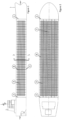
- FIG. 1 shown is a side elevation of a transport vessel, such as a ship.
- Gas transport assembly is enclosed within the hull of the ship, contained between the forward cargo bulkhead 1 and aft cargo bulkhead 2.
- a centerline longitudinal bulkhead 7, shown in Figure 2 divides the ship into two cargo holds, a starboard cargo hold and a port cargo hold.
- a plurality of pipes 3 is supported on bottom support members 5, which may be incorporated in the bottom of the ship's hull.
- Plurality of pipes 3 are located between a plurality of side support members 4, which may be part of the side hull of the ship and may be part of the centerline longitudinal bulkhead.
- Support members are spaced along the length of the cargo hold, typically equally spaced and aligned with each other as shown in Figures 1 and 2 .
- This embodiment of the invention shows that the cargo hold is free from any transverse bulkheads so the pipes can stretch almost the entire length of the cargo hold. If water tight transverse bulkheads are required, then these can be provided by means disclosed in Canadian patent no. 2,283,008 , such as placing a sealing material between the spaces formed by the hexagonally stacked pipes.
- Top forcing members 6 are spaced so top forcing members 6 align with the side support members, but are not connected to them.
- Centerline bulkhead 7 separates the port and starboard cargo holds and may incorporate the interior side support members.
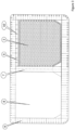
- Figure 3 shown is a cross-section taken along line 3-3 of Figure 1 .
- Figure 3 shows port cargo hold 8 without the plurality of pipes and shows the starboard cargo hold with the plurality of pipes 3 located therein. In practice, both the port and starboard cargo holds would be filled with pipe.
- the hull of the ship 9 surrounds the port and starboard cargo holds. In one embodiment, hull 9 incorporates the outside vertical support members, the top support members and the bottom support members. Longitudinal bulkhead 7 is part of the ship structure and also incorporates the inner side support members.
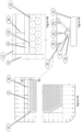
- the forcing member 6 is shown with the forcing mechanism being a plurality of jacks 10 between a forcing beam and the fixed top support member, which is part of the top deck of the ship.
- the forcing mechanism being a plurality of jacks 10 between a forcing beam and the fixed top support member, which is part of the top deck of the ship.
- Other means of generating the force required are contemplated. However, the force must be substantial enough to prevent movement of the pipes as described previously. In the embodiment of the invention described here the approximate range of force per jack is between 25 tonne and 125 tonne.
- FIG 4A is an expanded view of portions of Figure 3 .
- the plurality of pipe containing gas is surrounded by a layer of pipe 12 that will always be empty.
- the empty pipe 12 is denoted as 'MT' and the gas filled pipe is denoted as 'GAS'.
- the purpose of the empty pipe is to distribute the loads generated by the forcing mechanism as it pushes the empty pipes against the support members.
- the empty pipes distribute that concentrated load into the gas containing pipes to avoid concentrated loading of the gas carrying pipes. Other means of spreading the load such as using wooden poles or other materials are also contemplated.
- FIG. 4B there is one empty pipe shown to be slightly lower than the forcing beam.
- the gap could be caused by small differences in pipe geometry such as variances in diameter, out of roundness or other such differences.
- a gap would be found by visual inspection prior to applying the forcing mechanism. Shims 13 may be driven in the gap if the gap is visually obvious. If the gap is not visually obvious then the tightening of the jacks will ensure that some give will occur in one pipe and that the load will be equally shared.
- the fixed top support member 11 which is preferably fixed to the side support members 4. In this embodiment the support members are integrated into the ship's hull.
- FIG. 4C there is a means of bracing the forcing member 6 in the longitudinal direction to prevent any longitudinal loads pushing the forcing beam out of alignment.
- the bracing arms 14 provide support for the forcing beam in the longitudinal direction.
- the bracing arms are firmly secured after the forcing beam 6 has been fully loaded by the jacking system 10.
- One typical way to secure the bracing arms would be through a bolted flange 15 on the forcing beam and a similar bolted flange 16 on the top support member.
- FIG. 5A and 5B there is a means of filling each gas containing pipe with compressed gas using a manifold system.
- Figure 5A and 5B shows a preferred embodiment of a manifold system that maximizes the space for connection.
- Each pipe of the plurality of pipes has one tapered end and one closed end.
- the pipes are stacked so that each adjacent touching row has the open tapered end at alternating sides of the assemble. For example, all of the tapered open ends of the odd numbered rows would stacked so the open tapered end is forward and all of the even rows stacked so the open tapered end is aft.
- Each row of gas containing pipe 16 is connected to a manifold pipe 17. In this embodiment the connection is by means of a bolted flange 18. This and other joining mechanisms are well known, such as welding.
Description
- The invention relates to an apparatus and method for the marine storage and transport of gases, such as natural gas.
- There are known methods of transporting natural gas across bodies of water including for example, through subsea pipelines, by LNG ships as liquefied natural gas or by CNG ships as compressed natural gas (CNG). There are other known means such as converting the gas to gas hydrates or to a diesel-like liquid (GTL) and shipping the hydrates or GTL by ship. Currently, virtually all transport of natural gas across bodies of water is carried out by either subsea pipelines or LNG ships.
- The transport of liquefied natural gas (LNG) on ships is a large, well established industry but the transport of compressed natural gas (CNG) by ships or barges is almost non-existent. One of the major impediments to shipping CNG by sea is the cost of a CNG containment system that is suited to ship or barge transport. Thus, there is an ongoing need to design storage systems for compressed gases, such as CNG, that can contain large quantities of CNG and that are particularly suited to installation on or within ships and barges in a way that reduces the overall cost of the CNG ship or barge.
- The terrestrial transport of CNG by truck is well known. For decades CNG has been transported in tube-trailers. CNG is a common fuel for motor vehicles and a variety of CNG storage tanks are available for storing fuel in a motor vehicle. Also pipes of various dimensions are often transported by truck or in ships or on barges. It is well known in these industries that by strapping or holding down hexagonally stacked pipe with sufficient force enough friction can be generated to restrict pipes from slipping out of the stack under normal loads. Sometimes a frictional material is placed between the pipe layers to enhance the friction. However, none of these solutions have been able to provide a cost effective CNG ship or barge for the bulk transportation of large quantities of CNG.
- One of the preferred methods of constructing a CNG containment system for a ship or barge is to stack pipes longitudinally approximately the full length of the barge or ship in a hexagonal, close spaced fashion. One such method is disclosed in
Canadian patent number 2,283,008 filed September 22, 1999 . The CNG barge described in this patent had installed on its deck a gas storage assembly, which included a stack of horizontally oriented, long pipes stretching approximately the full length of the barge deck. The stacking was close spaced and one aspect of the invention was that the pipe could be stacked hexagonally together touching one another thus creating a friction bond. - While the barge and ship described in
Canadian patent no. 2,283,008 is a possible way to transport CNG, the invention did not take into account the motions of a barge or ship as pitches, yaws, and heaves in response to waves, currents and winds. Nor did it take into account the deflection of the barge or ship itself as it bends, twists and otherwise deflects as it is subjected to the loads caused by the waves. Nor did it take into account the expansion and contraction of the pipes as they are exposed to pressure and temperature changes that will occur as the pipes are loaded and emptied of compressed gas. The flexing and accelerations caused by the sea conditions and the differential temperatures and pressures caused by loading and unloading the pipe will cause the pipes to slide and move relative to each other and relative to the barge or ship. - The invention relates particularly to the marine gas transportation of non-liquefied compressed natural gas although it could be used to transport other gases. It is an object of the present invention to reduce the cost of ships or barges designed to carry compressed gases, such as CNG.
- A gas storage system particularly adapted for the transportation of large quantities of compressed gases, such as CNG, in or on a ship or a barge, primarily by means of long, straight hexagonally stacked lengths of pipe that are so strongly forced together that they cannot move relative to each other or to the ship and are connected by a manifold. Hereinafter the description will focus on a ship application to carry CNG below the top deck but it is obvious to one skilled in the art that this invention could also be employed on the top deck of the ship or on the top deck of a barge or below the top deck of a barge. It is also obvious to one skilled in the art that this invention could also be employed to carry compressed gases other than CNG.
- The pipe runs the almost the entire length of the ship in continuous straight lengths and is hexagonally packed and firmly pressed together by a forcing mechanism. As described in
Canadian patent number 2,283,008 the ship can be designed so that the holds of ship can be the entire length of the ship with the watertight transverse bulkheads being accommodated by filling the gaps between the hexagonally stacked pipes with a watertight material at the required intervals. The pipe diameter can be of any reasonable dimension, e.g., from approximately 8 inches (about 20 cm) to approximately 36 inches (about 90 cm) or other diameters. The precise diameter and length of pipe will depend on the economics of the system taking into account the cost of the various components making up the system, such as the cost of pipe materials, such as steel, and the connection manifold, at the time and location of construction. - This present invention is defined by
independent apparatus claim 1 directed to an assembly for transporting fluid, and byindependent method claim 8 directed to a method for transporting fluids in pipes. Accordingly, an assembly of long pipes, hexagonally stacked and touching one another within a barge or ship with a forcing mechanism that forces the pipes so firmly together that it firstly prevents any relative movement of the pipe as the ship, containing this system, moves in an open ocean environment. Secondly, the present invention prevents any strains caused by the flexing or twisting of the ship itself to be transmitted to the assembly of long pipes. Thirdly, the present invention prevents any relative movement between the individual pipes in the assembly caused by differential temperature or pressure. It accomplishes these goals by forcing the pipes so strongly together that the resulting friction between the pipes prevents any pipe from moving relative to the other in any circumstance, including the flexing of the ship itself. This requirement goes far beyond any friction element that would normally be employed to prevent slippage of one pipe relative to any other pipe as a stack of pipes would be transported by a truck or ship. As a way to picture this, it is like all of the pipes are fastened together in their entirety and to the ship or barge hull by means of a weld. By locking the pipes together by the friction caused by the forcing mechanism, the overall stiffness of the vessel is increased so that flexing and twisting of the vessel is significantly reduced and so that the assembly of pipes and the vessel move in unison. Increasing the overall strength of a barge or ship by means of forcing a plurality pipe sufficiently together so they act as though they are welded together and welded to the ship is unprecedented and novel. The purpose of doing this is to maximize the amount of CNG stored in the plurality of pipe that is contained within the space available either on the deck or in the holds of a ship or barge and thus create a lower cost means of transporting CNG. The assembly as claimed comprises notably: - i. a lower support and side supports fixed to each side of the lower support into which the plurality of pipes can be positioned. For example, the side supports are approximately perpendicular to the lower support.
- ii. a plurality of pipes for fluid containment, each pipe of the plurality of pipes having a means of connection to a manifold system, the plurality of pipes being stacked in a hexagonal manner on the lower support, between the side supports.
- iii. a top fixed support (not claimed) that does not move relative to the side supports, although both the top fixed support, the fixed side supports and the bottom support deflect slightly and elastically as the force is applied.
- iv. a forcing member, for example an upper forcing member beneath the top fixed support that is free to move up and down relative to the side supports and to forcefully bear down on the stack to apply compressive force to the plurality of pipes stacked in the hold that results in sufficient friction between the pipes. Such an assembly therefore
- a. prevents any significant relative motion between the pipes themselves or between the pipes and the lower support, the side supports or the forcing member.
- b. accomodates any relative motion of the barge or ship so that the hull of the barge or ship acts in concert with the plurality of pipes. In other words, the plurality of pipes adds to the strength of the barge or ship so that any motion induced by the environment on the ship or barge does not cause any relative motion between the hull and the plurality of pipes.
- c. prevents any relative movement of the individual pipes caused by differential pressures and temperatures.
- d. allows for adjustments of the force during the first pressure cycle to accommodate any shakedown that may occur. In some preferred examples of realisation:
- v. The forcing mechanism has bracing to provide longitudinal restraint to the forcing mechanism to prevent any longitudinal movement of the forcing mechanism in any conditions, for example, collision, or movements caused by waves, gas pressure or other factors.
- vi. a means of the generating the force on the forcing member.
- vii. a means of spreading the concentrated stresses generated by the compressive force forcing the pipes against the bottom, top, and side supports, such as a layer of empty pipe surrounding the gas containing pipe.
- viii. a means of connecting each of the of pipes to a manifold system for filling and unloading fluid, such as natural gas to the pipes.
- The evaluation of the required confining stress is non-trivial and unique to this invention. The relationship between these factors is critical to assess the required confining force to resist all loads, in particular longitudinal forces resulting from any event such as waves, collisions etc. This relationship is described in the equation below;
- N - is the number of gravitational accelerations to which the invention is subjected.
- C ƒ - is the coefficient of friction between bare steel pipe (approximately 0.70)
- P - is the confining pressure generated by the forcing mechanism described below
- L - is the length of the pipe
- d1 - is the outside diameter of a single pipe
- D - is the average of the height and width of the plurality of pipes
- Wp - is the weight of one pipe plus the weight of the fluid inside the pipe, such as compressed natural gas

- It is to be understood that other aspects of the present invention will become readily apparent to those skilled in the art from the following detailed description, wherein various embodiments of the invention are shown and described by way of illustration. In that regard, the top support member could be designed to also be the forcing member. The present invention is defined by the appended claims and in the following, the drawings and detailed description are to be regarded as illustrative in nature and not as restrictive.
- Referring to the drawings, several aspects of the present invention are illustrated by way of example and not by way of limitation, wherein:
-
Figure 1 is a side elevation of a ship according to the present invention; -
Figure 2 is a plan view of ships according to the present invention -
Figure 3 is a section along 3-3 ofFigure 1 , wherein a gas storage assembly according to the invention is more clearly shown; -
Figure 4A is an enlarged portion ofFigure 3 showing the forcingbeam 9, and the forcing mechanism, which in this case is a series ofjacks 10, to create the force on the forcing beam. -
Figure 4B is an enlarged potion ofFigure 4A showing how the force from the forcing beam can be exerted on all of the pipe, even if one or more pipes are not flush with the forcing beam; -
Figure 4C is asection 4C-4C ofFigure 4A showing how the forcing beams themselves are braced to resist the substantial longitudinal forces caused by the ships motion to ensure that they do not move relative to the pipes. -
Figure 5A is a front elevation view of a small portion of the manifold system showing two of the manifold pipes joining two rows of the plurality of pipes containing gas. -
Figure 5B is a side elevation view of a small portion of the manifold showing how the manifold is connected the gas containing pipes. - The description that follows and the embodiments described therein, are provided by way of illustration of an example, or examples, of particular embodiments of the principles of various aspects of the present invention. These examples are provided for the purposes of explanation, and not of limitation, of those principles and of the invention in its various aspects. In the description, similar parts are marked throughout the specification and the drawings with the same respective reference numerals. The drawings are not necessarily to scale and in some instances proportions may have been exaggerated in order more clearly to depict certain features.
- A compressed gas transport assembly is disclosed. The assembly of the invention may be installed on or in a ship or barge for marine transport of compressed gas such as CNG. For the purpose of this detailed description of the embodiments a ship is shown with the assembly inside the ship's hull. This is intended as a means of describing the invention and is not a limitation. It is readily apparent to those skilled in the art that the assembly could be modified by to be placed on the deck of a ship or barge, or in the hull of a barge.
- Referring to
Figure 1 , shown is a side elevation of a transport vessel, such as a ship. Gas transport assembly is enclosed within the hull of the ship, contained between theforward cargo bulkhead 1 andaft cargo bulkhead 2. A centerlinelongitudinal bulkhead 7, shown inFigure 2 , divides the ship into two cargo holds, a starboard cargo hold and a port cargo hold. A plurality ofpipes 3 is supported onbottom support members 5, which may be incorporated in the bottom of the ship's hull. Plurality ofpipes 3 are located between a plurality ofside support members 4, which may be part of the side hull of the ship and may be part of the centerline longitudinal bulkhead. These support members are spaced along the length of the cargo hold, typically equally spaced and aligned with each other as shown inFigures 1 and 2 . This embodiment of the invention shows that the cargo hold is free from any transverse bulkheads so the pipes can stretch almost the entire length of the cargo hold. If water tight transverse bulkheads are required, then these can be provided by means disclosed inCanadian patent no. 2,283,008 , such as placing a sealing material between the spaces formed by the hexagonally stacked pipes. - Referring to
Figure 2 , is a plan view of the ship is shown.Top forcing members 6 are spaced sotop forcing members 6 align with the side support members, but are not connected to them.Centerline bulkhead 7 separates the port and starboard cargo holds and may incorporate the interior side support members. - Referring to
Figure 3 , shown is a cross-section taken along line 3-3 ofFigure 1 . For illustrative purposes,Figure 3 showsport cargo hold 8 without the plurality of pipes and shows the starboard cargo hold with the plurality ofpipes 3 located therein. In practice, both the port and starboard cargo holds would be filled with pipe. The hull of theship 9 surrounds the port and starboard cargo holds. In one embodiment,hull 9 incorporates the outside vertical support members, the top support members and the bottom support members.Longitudinal bulkhead 7 is part of the ship structure and also incorporates the inner side support members. - The forcing
member 6 is shown with the forcing mechanism being a plurality ofjacks 10 between a forcing beam and the fixed top support member, which is part of the top deck of the ship. Other means of generating the force required are contemplated. However, the force must be substantial enough to prevent movement of the pipes as described previously. In the embodiment of the invention described here the approximate range of force per jack is between 25 tonne and 125 tonne. - Referring to
Figure 4A which is an expanded view of portions ofFigure 3 . The plurality of pipe containing gas is surrounded by a layer ofpipe 12 that will always be empty. Theempty pipe 12 is denoted as 'MT' and the gas filled pipe is denoted as 'GAS'. The purpose of the empty pipe is to distribute the loads generated by the forcing mechanism as it pushes the empty pipes against the support members. The empty pipes distribute that concentrated load into the gas containing pipes to avoid concentrated loading of the gas carrying pipes. Other means of spreading the load such as using wooden poles or other materials are also contemplated. - Referring to
Figure 4B there is one empty pipe shown to be slightly lower than the forcing beam. The gap could be caused by small differences in pipe geometry such as variances in diameter, out of roundness or other such differences. A gap would be found by visual inspection prior to applying the forcing mechanism.Shims 13 may be driven in the gap if the gap is visually obvious. If the gap is not visually obvious then the tightening of the jacks will ensure that some give will occur in one pipe and that the load will be equally shared. Also shown inFigure 4B is the fixedtop support member 11 which is preferably fixed to theside support members 4. In this embodiment the support members are integrated into the ship's hull. - Referring to
Figure 4C there is a means of bracing the forcingmember 6 in the longitudinal direction to prevent any longitudinal loads pushing the forcing beam out of alignment. The bracingarms 14 provide support for the forcing beam in the longitudinal direction. The bracing arms are firmly secured after the forcingbeam 6 has been fully loaded by the jackingsystem 10. One typical way to secure the bracing arms would be through a boltedflange 15 on the forcing beam and a similar boltedflange 16 on the top support member. - Referring to
Figure 5A and 5B , there is a means of filling each gas containing pipe with compressed gas using a manifold system. There are many ways to provide this required manifold system and these methods are generally known.Figure 5A and 5B shows a preferred embodiment of a manifold system that maximizes the space for connection. Each pipe of the plurality of pipes has one tapered end and one closed end. The pipes are stacked so that each adjacent touching row has the open tapered end at alternating sides of the assemble. For example, all of the tapered open ends of the odd numbered rows would stacked so the open tapered end is forward and all of the even rows stacked so the open tapered end is aft. Each row ofgas containing pipe 16 is connected to amanifold pipe 17. In this embodiment the connection is by means of a boltedflange 18. This and other joining mechanisms are well known, such as welding. - Thus, the present invention is well adapted to carry out the objectives and attain the ends and advantages mentioned above as well as those inherent therein. While presently preferred embodiments have been described for purposes of this disclosure, numerous changes and modifications will be apparent to those of ordinary skill in the art.
Claims (21)
- An assembly for transporting fluid comprising:a. a barge or ship comprising a cargo hold (8) including a lower support (5) and a side support (4) on each side of the lower support (5), said cargo hold (8) being upon or within the barge or ship (9);b. a plurality of pipes (3) for fluid containment, each pipe of the plurality of pipes having at least one end that is open, wherein the plurality of pipes (3) are stacked in a hexagonal manner and are oriented lengthwise and along almost the entire length of the barge or ship, in continuous lengths, the plurality of pipes being supported on the lower support (5) between each side support (4);c. a forcing member (6) that is configured to forcefully bear down on the plurality of pipes (3) via a forcing mechanism (10) to apply sufficient compressive force to the plurality of pipes (3) stacked in the cargo hold (8) so that friction between the pipes (3) will prevent any significant relative movement of the pipes caused by motions of the barge or ship (9), or by flexing of the barge or ship (9), or by strains caused by differential temperature or pressure;d. a fluid line system connected to the open ends of the plurality of pipes (3) for filling and unloading fluid to the pipes (3); ande. a stress-spreading structure between said forcing member (6) and said plurality of pipes (3) for spreading concentrated stresses generated by compressive forces exerted by said forcing mechanism (10), wherein said stress spreading structure is a layer of empty pipe (12) surrounding the plurality of pipes (3) for fluid containment.
- The assembly of claim 1 where the pipes (3) are made from steel.
- The assembly of claim 1 where the plurality of pipes (3) for fluid containment are surrounded by a plurality of empty pipes (12) of substantially the same outer diameter of the fluid containment pipes.
- The assembly of claim 1 where the forcing member (6) is a hold down beam and said forcing mechanism (10) is a jack between the hold down beam and a top fixed deck (11) of the hold (8).
- The assembly of claim 1 wherein a friction element is placed between the pipes (3), said friction element for maximizing friction between the pipes (3).
- The assembly of claim 1 where a space in the cargo hold (8) is filled with an inert gas.
- The assembly of claim 1 wherein the forcing mechanism (10) includes a tightening mechanism to permit pressing the upper forcing member down over the plurality of pipes after the first force is applied to accommodate settling in the plurality of pipes (3).
- A method of transporting fluid in pipes comprising the steps of:hexagonally stacking pipes (3) on or in a vessel (9) in a lengthwise orientation and along almost the entire length of the barge or ship, in continuous lengths; andforcing said pipes (3) together so strongly that any motion of the vessel (9), including flexing of the vessel (9) itself, does not induce relative motion between the pipes (3) themselves or between the pipes (3) and the vessel (9), wherein the pipes (3) contribute to the strength of the vessel (9) so said pipes (3) and said vessel (9) move together as though they were one; filling said hexagonally stacked pipes (3) with a fluid, wherein said fluid-containing pipes (3) are surrounded by a plurality of empty pipes (12).
- The method of claim 8 where the vessel (9) is a barge.
- The method of claim 8 where the vessel (9) is a ship.
- The method in claim 8 where the pipes (3) act as pressure vessels.
- The method according to claim 8 where the pipes (3) carry compressed gases such as compressed natural gas.
- The assembly according to claim 1 wherein:
said forcing mechanism (10) applies a force in a force direction; and further comprising bracing structure (14) for providing restraint in a direction perpendicular to said force direction. - The assembly according to claim 1 further comprising a means for connecting each one of said plurality of pipes (3) to a filling or emptying mechanism.
- The assembly according to claim 14 wherein said filling or emptying mechanism is a manifold system.
- The fluid transport assembly according to claim 1 wherein the cargo hold (8) is located within a hull of a vessel (9).
- The assembly according to claim 1 wherein the cargo hold (8) is located on a deck of said barge or said ship (9).
- The method according to claim 8 wherein said step of forcing comprises:
forcing said pipes (3) together with a hold down beam, said hold down beam acted upon by a forcing mechanism (10) between said hold down beam and a top fixed deck (11) of said vessel (9). - The method according to claim 18 wherein said forcing mechanism (10) is a plurality of jacks spaced over a length of said hold down beam.
- The method according to claim 19 wherein each of said plurality of jacks applies between 222 kN (25 tons) and 1112 kN (125) tons of force.
- The assembly according to claim 1 wherein said cargo hold (8) is one of a starboard cargo hold and a port cargo hold separated by a centerline longitudinal bulkhead (7) of said barge or ship (9).
Applications Claiming Priority (2)
| Application Number | Priority Date | Filing Date | Title |
|---|---|---|---|
| US201662374488P | 2016-08-12 | 2016-08-12 | |
| PCT/CA2017/050928 WO2018027308A1 (en) | 2016-08-12 | 2017-08-03 | Apparatus for gas storage and transport |
Publications (4)
| Publication Number | Publication Date |
|---|---|
| EP3497007A1 EP3497007A1 (en) | 2019-06-19 |
| EP3497007A4 EP3497007A4 (en) | 2020-03-25 |
| EP3497007C0 EP3497007C0 (en) | 2023-10-18 |
| EP3497007B1 true EP3497007B1 (en) | 2023-10-18 |
Family
ID=61161014
Family Applications (1)
| Application Number | Title | Priority Date | Filing Date |
|---|---|---|---|
| EP17838251.1A Active EP3497007B1 (en) | 2016-08-12 | 2017-08-03 | Apparatus for gas storage and transport |
Country Status (13)
| Country | Link |
|---|---|
| US (1) | US11480302B2 (en) |
| EP (1) | EP3497007B1 (en) |
| JP (1) | JP7022129B2 (en) |
| KR (1) | KR102386136B1 (en) |
| CN (1) | CN109890693B (en) |
| AU (1) | AU2017310280A1 (en) |
| BR (1) | BR112019002718A2 (en) |
| CA (1) | CA3033445A1 (en) |
| EA (1) | EA201990460A1 (en) |
| MX (1) | MX2019001703A (en) |
| PH (1) | PH12019500285A1 (en) |
| SG (2) | SG10202106264VA (en) |
| WO (1) | WO2018027308A1 (en) |
Families Citing this family (1)
| Publication number | Priority date | Publication date | Assignee | Title |
|---|---|---|---|---|
| US10752324B2 (en) * | 2018-12-31 | 2020-08-25 | Gev Technologies Pty. Ltd. | Pipe containment system for ships with spacing guide |
Citations (1)
| Publication number | Priority date | Publication date | Assignee | Title |
|---|---|---|---|---|
| CA2283008A1 (en) * | 1999-09-22 | 2001-03-22 | P. John Fitzpatrick | Ship or barge based compressed gas transport system |
Family Cites Families (15)
| Publication number | Priority date | Publication date | Assignee | Title |
|---|---|---|---|---|
| US2810265A (en) * | 1954-09-15 | 1957-10-22 | Constock Liquid Methane Corp | Means for storing and transporting cold low boiling liquids |
| FR2135575B1 (en) * | 1971-05-05 | 1973-07-13 | Liquid Gas Anlagen Union | |
| US3830180A (en) * | 1972-07-03 | 1974-08-20 | Litton Systems Inc | Cryogenic ship containment system having a convection barrier |
| DE2247220A1 (en) * | 1972-09-27 | 1974-03-28 | Linde Ag | DEVICE FOR TRANSPORTING LOW-BOILING LIQUID GASES |
| US5040933A (en) * | 1990-05-08 | 1991-08-20 | Union Carbide Industrial Gases Technology Corporation | Trailer for cylindrical container modules |
| US5839383A (en) * | 1995-10-30 | 1998-11-24 | Enron Lng Development Corp. | Ship based gas transport system |
| JP4927239B2 (en) * | 1995-10-30 | 2012-05-09 | シー エヌジー コーポレイション | Ship transportation system for compressed natural gas |
| US6584781B2 (en) * | 2000-09-05 | 2003-07-01 | Enersea Transport, Llc | Methods and apparatus for compressed gas |
| NO319876B1 (en) * | 2003-07-09 | 2005-09-26 | Statoil Asa | System for storing or transporting compressed gas on a liquid structure |
| US7651554B2 (en) * | 2007-10-26 | 2010-01-26 | Ovonic Hydrogen Systems Llc | Hydrogen storage system |
| US8091495B2 (en) * | 2008-06-09 | 2012-01-10 | Frank Wegner Donnelly | Compressed natural gas barge |
| DE202008014254U1 (en) * | 2008-10-25 | 2009-01-29 | Eurotank Gmbh | Trailer for transporting gas cylinders |
| EP2748512B1 (en) * | 2011-08-22 | 2018-12-19 | Tranzgaz Inc. | Method of fabricating type 4 cylinders and arranging in transportation housings for transport of gaseous fluids |
| US9975609B2 (en) * | 2014-06-11 | 2018-05-22 | GEV Canada Corporation | Ship for gas storage and transport |
| US10752324B2 (en) * | 2018-12-31 | 2020-08-25 | Gev Technologies Pty. Ltd. | Pipe containment system for ships with spacing guide |
-
2017
- 2017-08-03 US US16/325,027 patent/US11480302B2/en active Active
- 2017-08-03 WO PCT/CA2017/050928 patent/WO2018027308A1/en unknown
- 2017-08-03 KR KR1020197007216A patent/KR102386136B1/en active IP Right Grant
- 2017-08-03 EA EA201990460A patent/EA201990460A1/en unknown
- 2017-08-03 SG SG10202106264VA patent/SG10202106264VA/en unknown
- 2017-08-03 EP EP17838251.1A patent/EP3497007B1/en active Active
- 2017-08-03 BR BR112019002718-1A patent/BR112019002718A2/en not_active IP Right Cessation
- 2017-08-03 SG SG11201901136YA patent/SG11201901136YA/en unknown
- 2017-08-03 AU AU2017310280A patent/AU2017310280A1/en not_active Abandoned
- 2017-08-03 JP JP2019529303A patent/JP7022129B2/en active Active
- 2017-08-03 CA CA3033445A patent/CA3033445A1/en not_active Abandoned
- 2017-08-03 CN CN201780061494.6A patent/CN109890693B/en active Active
- 2017-08-03 MX MX2019001703A patent/MX2019001703A/en unknown
-
2019
- 2019-02-11 PH PH12019500285A patent/PH12019500285A1/en unknown
Patent Citations (1)
| Publication number | Priority date | Publication date | Assignee | Title |
|---|---|---|---|---|
| CA2283008A1 (en) * | 1999-09-22 | 2001-03-22 | P. John Fitzpatrick | Ship or barge based compressed gas transport system |
Also Published As
| Publication number | Publication date |
|---|---|
| SG11201901136YA (en) | 2019-03-28 |
| CN109890693A (en) | 2019-06-14 |
| WO2018027308A1 (en) | 2018-02-15 |
| EP3497007A4 (en) | 2020-03-25 |
| EP3497007C0 (en) | 2023-10-18 |
| SG10202106264VA (en) | 2021-07-29 |
| US20200011481A1 (en) | 2020-01-09 |
| EP3497007A1 (en) | 2019-06-19 |
| KR20190042611A (en) | 2019-04-24 |
| EA201990460A1 (en) | 2019-07-31 |
| JP2019524563A (en) | 2019-09-05 |
| CA3033445A1 (en) | 2018-02-15 |
| MX2019001703A (en) | 2019-09-26 |
| BR112019002718A2 (en) | 2019-05-14 |
| KR102386136B1 (en) | 2022-04-12 |
| PH12019500285A1 (en) | 2019-10-28 |
| AU2017310280A1 (en) | 2019-03-07 |
| CN109890693B (en) | 2021-04-30 |
| JP7022129B2 (en) | 2022-02-17 |
| US11480302B2 (en) | 2022-10-25 |
Similar Documents
| Publication | Publication Date | Title |
|---|---|---|
| CN101473163A (en) | An arrangement for a cylindrical tank for transportation of liquefied gases at low temperature in a ship | |
| CN105658516A (en) | Lashing bridge for a cargo ship | |
| KR102498803B1 (en) | sealed and insulated tank | |
| CN109307147B (en) | Sealed thermally insulated tank comprising an angular bracket | |
| CN111742173B (en) | Fluid-tight container wall comprising a sealing membrane with reinforced areas | |
| US11254393B2 (en) | Pipe containment system for ships with spacing guide | |
| EP3497007B1 (en) | Apparatus for gas storage and transport | |
| KR102438160B1 (en) | Fluid sealed and insulated fluid storage tank | |
| KR20210146246A (en) | Anchor device intended to retain insulating blocks | |
| KR20230118925A (en) | gas storage and transport | |
| Jurišić et al. | Structural aspects during conversion from general cargo ships to cement carriers | |
| KR102622457B1 (en) | Liquefied gas storage facility | |
| KR20210058937A (en) | Storage facilities for liquefied gas | |
| US20020124784A1 (en) | Re-use of vessels for transporting deck payloads | |
| KR20230066072A (en) | sealed and insulated tank | |
| KR20220038360A (en) | Sealed Insulated Tanks for Floating Structures | |
| CN117881919A (en) | Storage facility for liquefied gas | |
| DK2999823T3 (en) | PORT STOCK FOR LIQUID FUEL |
Legal Events
| Date | Code | Title | Description |
|---|---|---|---|
| STAA | Information on the status of an ep patent application or granted ep patent |
Free format text: STATUS: THE INTERNATIONAL PUBLICATION HAS BEEN MADE |
|
| PUAI | Public reference made under article 153(3) epc to a published international application that has entered the european phase |
Free format text: ORIGINAL CODE: 0009012 |
|
| STAA | Information on the status of an ep patent application or granted ep patent |
Free format text: STATUS: REQUEST FOR EXAMINATION WAS MADE |
|
| 17P | Request for examination filed |
Effective date: 20190219 |
|
| AK | Designated contracting states |
Kind code of ref document: A1 Designated state(s): AL AT BE BG CH CY CZ DE DK EE ES FI FR GB GR HR HU IE IS IT LI LT LU LV MC MK MT NL NO PL PT RO RS SE SI SK SM TR |
|
| AX | Request for extension of the european patent |
Extension state: BA ME |
|
| RAP1 | Party data changed (applicant data changed or rights of an application transferred) |
Owner name: GEV TECHNOLOGIES PTY. LTD |
|
| DAV | Request for validation of the european patent (deleted) | ||
| DAX | Request for extension of the european patent (deleted) | ||
| A4 | Supplementary search report drawn up and despatched |
Effective date: 20200226 |
|
| RIC1 | Information provided on ipc code assigned before grant |
Ipc: B63B 25/00 20060101ALI20200220BHEP Ipc: F17C 1/00 20060101ALI20200220BHEP Ipc: B63B 35/00 20200101ALI20200220BHEP Ipc: B63B 25/24 20060101ALI20200220BHEP Ipc: B63B 25/14 20060101AFI20200220BHEP Ipc: F17C 5/06 20060101ALI20200220BHEP |
|
| STAA | Information on the status of an ep patent application or granted ep patent |
Free format text: STATUS: EXAMINATION IS IN PROGRESS |
|
| 17Q | First examination report despatched |
Effective date: 20220221 |
|
| GRAP | Despatch of communication of intention to grant a patent |
Free format text: ORIGINAL CODE: EPIDOSNIGR1 |
|
| STAA | Information on the status of an ep patent application or granted ep patent |
Free format text: STATUS: GRANT OF PATENT IS INTENDED |
|
| INTG | Intention to grant announced |
Effective date: 20221207 |
|
| GRAJ | Information related to disapproval of communication of intention to grant by the applicant or resumption of examination proceedings by the epo deleted |
Free format text: ORIGINAL CODE: EPIDOSDIGR1 |
|
| STAA | Information on the status of an ep patent application or granted ep patent |
Free format text: STATUS: EXAMINATION IS IN PROGRESS |
|
| INTC | Intention to grant announced (deleted) | ||
| GRAP | Despatch of communication of intention to grant a patent |
Free format text: ORIGINAL CODE: EPIDOSNIGR1 |
|
| STAA | Information on the status of an ep patent application or granted ep patent |
Free format text: STATUS: GRANT OF PATENT IS INTENDED |
|
| INTG | Intention to grant announced |
Effective date: 20230530 |
|
| GRAS | Grant fee paid |
Free format text: ORIGINAL CODE: EPIDOSNIGR3 |
|
| GRAA | (expected) grant |
Free format text: ORIGINAL CODE: 0009210 |
|
| STAA | Information on the status of an ep patent application or granted ep patent |
Free format text: STATUS: THE PATENT HAS BEEN GRANTED |
|
| AK | Designated contracting states |
Kind code of ref document: B1 Designated state(s): AL AT BE BG CH CY CZ DE DK EE ES FI FR GB GR HR HU IE IS IT LI LT LU LV MC MK MT NL NO PL PT RO RS SE SI SK SM TR |
|
| REG | Reference to a national code |
Ref country code: GB Ref legal event code: FG4D |
|
| REG | Reference to a national code |
Ref country code: CH Ref legal event code: EP |
|
| REG | Reference to a national code |
Ref country code: IE Ref legal event code: FG4D |
|
| REG | Reference to a national code |
Ref country code: DE Ref legal event code: R096 Ref document number: 602017075530 Country of ref document: DE |
|
| U01 | Request for unitary effect filed |
Effective date: 20231114 |
|
| U07 | Unitary effect registered |
Designated state(s): AT BE BG DE DK EE FI FR IT LT LU LV MT NL PT SE SI Effective date: 20240102 |
|
| PG25 | Lapsed in a contracting state [announced via postgrant information from national office to epo] |
Ref country code: GR Free format text: LAPSE BECAUSE OF FAILURE TO SUBMIT A TRANSLATION OF THE DESCRIPTION OR TO PAY THE FEE WITHIN THE PRESCRIBED TIME-LIMIT Effective date: 20240119 |
|
| PG25 | Lapsed in a contracting state [announced via postgrant information from national office to epo] |
Ref country code: IS Free format text: LAPSE BECAUSE OF FAILURE TO SUBMIT A TRANSLATION OF THE DESCRIPTION OR TO PAY THE FEE WITHIN THE PRESCRIBED TIME-LIMIT Effective date: 20240218 |