EP3496607B1 - Device, system and method for fall detection - Google Patents
Device, system and method for fall detection Download PDFInfo
- Publication number
- EP3496607B1 EP3496607B1 EP17751711.7A EP17751711A EP3496607B1 EP 3496607 B1 EP3496607 B1 EP 3496607B1 EP 17751711 A EP17751711 A EP 17751711A EP 3496607 B1 EP3496607 B1 EP 3496607B1
- Authority
- EP
- European Patent Office
- Prior art keywords
- subject
- video data
- sensor
- signal features
- fall
- Prior art date
- Legal status (The legal status is an assumption and is not a legal conclusion. Google has not performed a legal analysis and makes no representation as to the accuracy of the status listed.)
- Active
Links
Images

Classifications
-
- A—HUMAN NECESSITIES
- A61—MEDICAL OR VETERINARY SCIENCE; HYGIENE
- A61B—DIAGNOSIS; SURGERY; IDENTIFICATION
- A61B5/00—Measuring for diagnostic purposes; Identification of persons
- A61B5/103—Measuring devices for testing the shape, pattern, colour, size or movement of the body or parts thereof, for diagnostic purposes
- A61B5/11—Measuring movement of the entire body or parts thereof, e.g. head or hand tremor or mobility of a limb
- A61B5/1116—Determining posture transitions
- A61B5/1117—Fall detection
-
- A—HUMAN NECESSITIES
- A61—MEDICAL OR VETERINARY SCIENCE; HYGIENE
- A61B—DIAGNOSIS; SURGERY; IDENTIFICATION
- A61B5/00—Measuring for diagnostic purposes; Identification of persons
- A61B5/103—Measuring devices for testing the shape, pattern, colour, size or movement of the body or parts thereof, for diagnostic purposes
- A61B5/11—Measuring movement of the entire body or parts thereof, e.g. head or hand tremor or mobility of a limb
- A61B5/1126—Measuring movement of the entire body or parts thereof, e.g. head or hand tremor or mobility of a limb using a particular sensing technique
- A61B5/1128—Measuring movement of the entire body or parts thereof, e.g. head or hand tremor or mobility of a limb using a particular sensing technique using image analysis
-
- A—HUMAN NECESSITIES
- A61—MEDICAL OR VETERINARY SCIENCE; HYGIENE
- A61B—DIAGNOSIS; SURGERY; IDENTIFICATION
- A61B5/00—Measuring for diagnostic purposes; Identification of persons
- A61B5/68—Arrangements of detecting, measuring or recording means, e.g. sensors, in relation to patient
- A61B5/6801—Arrangements of detecting, measuring or recording means, e.g. sensors, in relation to patient specially adapted to be attached to or worn on the body surface
- A61B5/6802—Sensor mounted on worn items
- A61B5/681—Wristwatch-type devices
-
- A—HUMAN NECESSITIES
- A61—MEDICAL OR VETERINARY SCIENCE; HYGIENE
- A61B—DIAGNOSIS; SURGERY; IDENTIFICATION
- A61B5/00—Measuring for diagnostic purposes; Identification of persons
- A61B5/72—Signal processing specially adapted for physiological signals or for diagnostic purposes
- A61B5/7235—Details of waveform analysis
- A61B5/7246—Details of waveform analysis using correlation, e.g. template matching or determination of similarity
-
- G—PHYSICS
- G08—SIGNALLING
- G08B—SIGNALLING SYSTEMS, e.g. PERSONAL CALLING SYSTEMS; ORDER TELEGRAPHS; ALARM SYSTEMS
- G08B21/00—Alarms responsive to a single specified undesired or abnormal condition and not otherwise provided for
- G08B21/02—Alarms for ensuring the safety of persons
- G08B21/04—Alarms for ensuring the safety of persons responsive to non-activity, e.g. of elderly persons
- G08B21/0407—Alarms for ensuring the safety of persons responsive to non-activity, e.g. of elderly persons based on behaviour analysis
- G08B21/043—Alarms for ensuring the safety of persons responsive to non-activity, e.g. of elderly persons based on behaviour analysis detecting an emergency event, e.g. a fall
-
- G—PHYSICS
- G08—SIGNALLING
- G08B—SIGNALLING SYSTEMS, e.g. PERSONAL CALLING SYSTEMS; ORDER TELEGRAPHS; ALARM SYSTEMS
- G08B21/00—Alarms responsive to a single specified undesired or abnormal condition and not otherwise provided for
- G08B21/02—Alarms for ensuring the safety of persons
- G08B21/04—Alarms for ensuring the safety of persons responsive to non-activity, e.g. of elderly persons
- G08B21/0438—Sensor means for detecting
- G08B21/0446—Sensor means for detecting worn on the body to detect changes of posture, e.g. a fall, inclination, acceleration, gait
-
- G—PHYSICS
- G08—SIGNALLING
- G08B—SIGNALLING SYSTEMS, e.g. PERSONAL CALLING SYSTEMS; ORDER TELEGRAPHS; ALARM SYSTEMS
- G08B21/00—Alarms responsive to a single specified undesired or abnormal condition and not otherwise provided for
- G08B21/02—Alarms for ensuring the safety of persons
- G08B21/04—Alarms for ensuring the safety of persons responsive to non-activity, e.g. of elderly persons
- G08B21/0438—Sensor means for detecting
- G08B21/0476—Cameras to detect unsafe condition, e.g. video cameras
-
- G—PHYSICS
- G08—SIGNALLING
- G08B—SIGNALLING SYSTEMS, e.g. PERSONAL CALLING SYSTEMS; ORDER TELEGRAPHS; ALARM SYSTEMS
- G08B21/00—Alarms responsive to a single specified undesired or abnormal condition and not otherwise provided for
- G08B21/02—Alarms for ensuring the safety of persons
- G08B21/04—Alarms for ensuring the safety of persons responsive to non-activity, e.g. of elderly persons
- G08B21/0438—Sensor means for detecting
- G08B21/0492—Sensor dual technology, i.e. two or more technologies collaborate to extract unsafe condition, e.g. video tracking and RFID tracking
-
- G—PHYSICS
- G08—SIGNALLING
- G08B—SIGNALLING SYSTEMS, e.g. PERSONAL CALLING SYSTEMS; ORDER TELEGRAPHS; ALARM SYSTEMS
- G08B25/00—Alarm systems in which the location of the alarm condition is signalled to a central station, e.g. fire or police telegraphic systems
- G08B25/01—Alarm systems in which the location of the alarm condition is signalled to a central station, e.g. fire or police telegraphic systems characterised by the transmission medium
- G08B25/016—Personal emergency signalling and security systems
-
- A—HUMAN NECESSITIES
- A61—MEDICAL OR VETERINARY SCIENCE; HYGIENE
- A61B—DIAGNOSIS; SURGERY; IDENTIFICATION
- A61B2562/00—Details of sensors; Constructional details of sensor housings or probes; Accessories for sensors
- A61B2562/02—Details of sensors specially adapted for in-vivo measurements
- A61B2562/0219—Inertial sensors, e.g. accelerometers, gyroscopes, tilt switches
-
- A—HUMAN NECESSITIES
- A61—MEDICAL OR VETERINARY SCIENCE; HYGIENE
- A61B—DIAGNOSIS; SURGERY; IDENTIFICATION
- A61B5/00—Measuring for diagnostic purposes; Identification of persons
- A61B5/68—Arrangements of detecting, measuring or recording means, e.g. sensors, in relation to patient
- A61B5/6801—Arrangements of detecting, measuring or recording means, e.g. sensors, in relation to patient specially adapted to be attached to or worn on the body surface
- A61B5/6802—Sensor mounted on worn items
- A61B5/6803—Head-worn items, e.g. helmets, masks, headphones or goggles
Definitions
- the present invention relates to a device, system and method for fall detection.
- Falling is a widely recognized issue that adversely affects the lives of a substantial part of the population, including elderly, hospital patients, and people with assistance requirements.
- Fall detectors provide a notification/alarm about a person having fallen. This can fulfil the needs of providing earlier assistance, better incident reporting, and may prevent (some) recurrence of falls.
- a number of fall detectors based on wearable sensors have been described and are commercially available. Fall detectors based on video data are also known, although they have not yet found their way into valid products.
- Fall detectors based solely on wearable sensors often exhibit insufficient detection accuracy in demanding situations. Moreover they do not provide the location of the fallen wearer, which can delay proper assessment of the event localization of the wearer and the arrival of assistance. Fall detectors based solely on video data are currently immature, generally exhibiting poor detection accuracy in realistic usage conditions and known issues with occlusions and poor lighting conditions.
- US 2015/0112151 appears to describe a patient movement sensor which receives input from at least position sensors and an IR camera.
- a fall warning alarm is issued if position sensor data and IR camera data both indicate that a fall has occurred or is about to occur.
- a similar device is also known from US 2015/0318015 A1 .
- US 2012/0314901 describes a fall detection technology in which motion sensor information and image-based analysis is used to detect a fall.
- a system may combine motion sensor information with image-based analysis.
- a device for fall detection comprising: a sensor input for obtaining sensor data related to movement of a subject acquired by a sensor, a video input for obtaining video data of the subject and/or the subject's environment, an analysis unit for analyzing the obtained sensor data to detect one or more signal features indicative of a potential fall of the subject and for analyzing, if one or more such signal features have been detected, the detected one or more signal features and/or related sensor data in combination with related video data to identify similarities in: changes of the related sensor data and/or the signal features over time; and changes of the video data over time, and an output for issuing a fall detection indication if the level and/or amount of detected similarities exceeds a corresponding threshold; the analysis unit is configured to analyze the detected one or more signal features and/or relative sensor data in combination with the related video data in response to the signal features indicating that a possible fall has been identified; and the analysis unit is configured to estimate the relative vertical velocity and/or acceleration of the subject from the video data and to correlate it
- a system for fall detection comprising: a sensor for acquiring sensor data related to movement of a subject, a video acquisition unit for acquiring video data of the subject and/or the subject's environment, and a device as disclosed herein for detecting a potential fall of the subject from the acquired sensor data and video data.
- the present invention is based on the idea to detect a fall of a subject (i.e. a person) by using a clever combination sensor data related to movement of a subject and video data of the subject and/or the subject's environment.
- the sensor data is processed to derive signal features the values of which are indicative of a possible fall of the wearer.
- the raw sensor data and/or it derived signal features are processed together with the video data.
- An algorithm may e.g. be used to compare the evolution of the received video-based and wearable-based signal/feature streams, looking for similarities in changes of the video-based and wearable-based streams over time. When enough similarities are found, the algorithm may decide that the possible fall is confirmed and may issue an alarm to a user (e.g. a nurse). Further, the video stream from the camera where the correspondence was found may be presented to the user. After assessing the presented picture/video, the user may want to cancel the alarm and/or rush to the location of the selected camera to aid the fallen subject.
- the invention thereby provides a more reliable fall detection device, as the similarity between the progress of a fall, as monitored using two different sensing methods, is used to ascertain whether a fall has occurred or not. This reduces a likelihood that a fall will be falsely detected.
- a predetermined threshold e.g. 10 or more similarities or a correlation score greater than 0.5
- a comparison may be made between a temporal pattern of the sensor data and a temporal pattern of the video data to determine whether there are similarities between the changes of the sensor data and the changes of the video data.
- a number of maxima and/or minima in a data signal may represent, for example, a pattern of the associated data.
- a correlation may be performed between the sensor data and the video data.
- an algorithm may generally use any plurality of distance or similarity measures between the two video data and the sensor data.
- a similarity measure value may be generated based on the plurality of results (e.g. a correlation coefficient).
- a (possibly dynamic) threshold may be established for the similarity measure value for triggering the detection. For instance, if a correlation coefficient determined from the video data and the sensor data exceeds the threshold, a similarity between the changes of the video data and the sensor data over time may be assumed to be detected.
- an interdependence between two sets of data may be determined. This may allow for a more accurate identification of a potential fall by correlating the data.
- a correlation between time dependent functions representing the sensor data and the video data respectively may result in a value representative of the similarities between the changes of the sensor data over time and the changes of the video data over time.
- video data of the subject's environment may generally be understood as video data of any area and environment where the subject may be encountered, including e.g. the subject's room, the subject's home, but also public areas e.g. around the hospital visible in surveillance cameras.
- said analysis unit is configured to identify similarities in timing, speed, duration, intensity and/or evolution of changes.
- the kind of similarities that are identified may depend on the kind of sensor data and the kind of sensor used for acquiring the sensor data. For instance, signal features and similarities of changes of these signal features may be used that show significant changes and can thus be easily recognized as indicators for a potential fall of the subject.
- said analysis unit is configured to detect as signal feature indicative of a potential fall of the subject one or more of impact, maxima, minima, zero crossings, acceleration in vertical direction, velocity in vertical direction, height change, inclination before and/or after a potential fall, activity level before and/or after a potential fall, and intensity change. Such features are particularly helpful and indicative of a potential fall.
- Said analysis unit may further be configured to estimate the relative vertical velocity and/or acceleration of the subject from the video data and to correlate it with a vertical acceleration and/or vertical velocity derived from the sensor data to identify similarities. This improves the accuracy of the detection of a potential fall.
- Said analysis unit may hereby be further configured to determine a vertical velocity map from the video data and estimate the relative vertical velocity and/or acceleration of the subject from said vertical velocity map.
- the vertical velocity map may thus be used to indicate local velocities, e.g. of different body areas of the subject's body.
- said analysis unit is configured to analyze different video data streams acquired by different video data acquisition units to identify similarities between: changes of the related sensor data and/or the signal features over time; and changes of the video data over time. This ensures a higher accuracy of the detection of a potential fall.
- the analysis unit may further be configured to analyze the obtained video data to detect one or more signal features indicative of a potential fall of the subject and to analyze, if in addition to the detection of one or more signal features indicative of a potential fall of the subject indications of a potential fall of the subject have been detected in the video data, the detected one or more signal features and/or the related sensor data in combination with the related video data to identify similarities between: changes of the related sensor data and/or the signal features over time; and changes of the video data over time.
- the use of the video data already for detecting indications of a potential fall may further improve the detection of a potential fall.
- the output is preferably configured to additionally issue a video data portion and/or sensor data portion and/or identified signal features related to an identified potential fall. This may help the user to make an opinion on the situation and to decide on required measures to be taken, e.g. if personal help is immediately required by the subject or if the situation of the subject is harmless. Further, this might help the user to find the location of the fallen subject more easily. In a system using multiple cameras this may include selecting the right camera (e.g. video data from a camera which is linked to a location in the hospital) for presentation to the user (e.g. nurse).
- the right camera e.g. video data from a camera which is linked to a location in the hospital
- the sensor of the system used for acquiring the sensor data may include one or more sensor elements worn by the subject, e.g. using a sticker, a chest belt, a wristband, etc., or may include one or more sensor elements that are arranged in the subject's environment, e.g. in the bed of the subject.
- Such sensors may include one or more of a movement sensor, an accelerometer, a pressure sensor, a bed camera and an inertial sensor.
- smartphones conventionally include an inertial sensor which may be used as sensor in the proposed system to acquire sensor data related to movement of the subject, as long as the smartphone is carried by the subject, e.g. in the pocket of the subject's jacket or trousers.
- These sensor elements may provide additional information and/or confirmation that the subject in question is not in the bed but outside of the bed.
- the video acquisition unit used for acquiring the video data may include a body-worn camera worn by the subject for acquiring video data of the subject's environment and/or a stationary or mobile camera for acquiring video data of the subject, in particular an RGB camera and/or an infrared camera.
- the senor, the video acquisition unit and the device are integrated into a user device, in particular a smartphone, a camera, a watch or glasses.
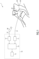
- Fig. 1 shows a schematic diagram of a first embodiment of a system 1 and a device 10 according to the present invention for fall detection of a subject 40, e.g. a patient in a hospital, an elderly person in a care station or rest home, a person at home, a child in a bed, etc.
- a subject 40 e.g. a patient in a hospital, an elderly person in a care station or rest home, a person at home, a child in a bed, etc.
- the subject 40 is a patient lying in a bed 50, e.g. in a hospital.
- the system 1 comprises at least one sensor 20 for acquiring sensor data related to movement of a subject 40.
- the sensor 20 is a body-worn inertial sensor such as an accelerometer that is fixed to the subject's body by a chest belt.
- the sensor 20 is able to detect movements of the subject's body and to generate sensor data 21 representing such movements.
- the system 1 further comprises a video acquisition unit 30 for acquiring video data 31 of the subject and/or the subject's environment, in this case a stationary or mobile camera for acquiring video data of the subject 40, in particular an RGB camera and/or an infrared camera.
- the camera 30 is e.g. mounted to the ceiling and monitors the whole bed 50 as is commonly the case, for example, in video surveillance applications.
- the system 1 further comprises a device 10 for detecting a potential fall of the subject 40 from the acquired sensor data 21 and video data 31.
- the device 10 comprises a sensor input 11 for obtaining (i.e. receiving or retrieving) the sensor data 21 related to movement of a subject acquired by the sensor 20 and a video input 12 for obtaining (i.e. receiving or retrieving) the video data 31 of the subject 40 and/or the subject's environment (e.g. the bed 50 and the area around the bed 50).
- the sensor 20 and the camera 30 may be connected to the device 10 through wires (e.g.
- the sensor input 11 and the video input 12 may thus e.g. be corresponding data interfaces, such as a Bluetooth interface, a Wi-Fi interface, wired terminals, etc.
- the device 10 further comprises an analysis unit 13 for analyzing the obtained sensor data 21 to detect one or more signal features indicative of a potential fall of the subject 40 and for analyzing, if one or more such signal features have been detected, the detected one or more signal features and/or the related sensor data 21 in combination with the related video data 31 to identify similarities of changes of the analyzed signal features, sensor data and video data indicating a potential fall of the subject 40.
- the analysis unit 13 may e.g. be implemented in hard- and/or software, as one or more programmed processors or computers (e.g. a hospital workstation, a caregiver's PC, etc.) or as an application running on a user device (e.g. a smartphone, laptop, tablet, etc.).
- the device 10 further comprises an output 14 for issuing a fall detection indication if the level and/or amount of detected similarities exceeds a corresponding threshold.
- the output 14 may e.g. an output interface for communicating the fall detection indication, e.g. an alarm notice, to a remote destination, e.g. a nurse's user device, a central supervision monitor, etc., or may be a user interface, like a display and/or loudspeaker, that directly issues a (visible and/or audible) notice that a potential fall of a particular subject has been detected.
- potential user falls are detected by using a combination of sensor data and video (camera) data.
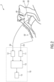
- Fig. 2 shows a schematic diagram of a second embodiment of a system 2 and a device 10 according to the present invention.
- the device 10 in this embodiment generally has the same layout as the device 10 shown in Fig. 1 .
- the body-worn sensor 20 one or more pressure sensors 22 (e.g. an array of pressure sensors) are used that are in this exemplary embodiment arranged within or on top of the mattress and acquire sensor data 23 that reflect movements of the subject 40.
- a body-worn camera 32 is worn by the subject 40 for acquiring video data 33 of the subject's environment.
- the device 10 obtains the sensor data 23 and the video data 33 and processes them to detect a potential fall of the subject.
- a body worn camera 32 has the advantage that the subject 40 can walk around and that also falls of the subject during walking, e.g. in the bathroom, on the stairs, etc., can be detected, provided the subject 40 wears a body-worn sensor 20 as shown in the first embodiment.
- a larger area e.g. a complete home or hospital station may be provided with a plurality of cameras that monitor a larger area, i.e. the analysis unit 13 obtains and analyses video data from a plurality of cameras.
- the user device in this exemplary embodiment the smartphone, may be worn as a pendant or attached to the clothes.
- the video stream is sent to the user, e.g. a nurse, who can determine the severity of the fall from the video data (e.g. whether the subject is lying on the floor after the event). The location of the fall may also be determined based on the video data.
- the sensor data is processed to derive signal features the values of which are indicative of a possible fall of the subject.
- signal features may be one or more of impact, maxima/minima/zero-crossings of the accelerometer norm (e.g. of 3-axis acceleration vector data), vertical acceleration, vertical velocity, inclination before/after the event, activity level before/after the event, and height change estimates.
- the raw sensor data and/or its derived signal features are transmitted to the analysis unit, which has also access to the video data stream of one or more video cameras.
- An algorithm may then be used to compare the evolution of the received video-based and sensor-based signal/feature streams, looking for similarities such as in timing, speed and evolution of changes. Changes that occur in the vertical axis (e.g. during a person's descent to the ground) and/or due to the impact on the ground are of special relevance.
- an image area corresponding to the subject is segmented and tracked from one frame (of the video data) to another.
- the relative vertical velocity of the k th object v z (k,t) as a function of time t is estimated in segments of a few frames.
- the vertical motion velocity in the image plane is estimated for all points to obtain a vertical velocity map v z (i, j, ,t) where i and j are positions in the image plane.
- a vertical velocity corresponding to a number of objects in the image may be obtained.
- the velocity may be computed for a number of areas in the image. There are conversions between the two representations of vertical motion in the image.
- the vertical velocity of a single object (such as a person's body) in the plane is v z (t).
- the observed vertical acceleration from the accelerometer signal is given by a z (t) .
- the step-size between the time points (i.e. the size of a discretized dt) when performing the calculation of equations (1) and (2) is less than the event length of a potential fall.
- the step-size may be less than 0.1s or less than 0.1ms.
- a plurality of data points for each of the sensor data and video data are taken over time. Thus, multiple data points are used for performing a similarity check.
- the correlation computation calculates the relationship between these data points, to give a measure of the similarities (i.e. a similarity measure value) between the between changes of the sensor data over time and changes of the video data over time.
- a value of this correlation may be compared to a threshold value to determine whether or not a fall has occurred.
- a correlation value greater than 0.5 or 0.6 may indicate that a fall is likely to have occurred.
- the features to correlate the sensor data (in particular accelerometer data) with the video data can also be unrelated to those exclusively calculated for a fall detection algorithm, e.g. a step detection gait feature that is already computed on the sensor, with the advantage that there is no additional effort needed for feature computation.
- the correlation operation typically contains normalization (e.g. using Pearson correlation coefficient) such that correlation values between the sensor data and the video data can be compared at different times.
- the normalization may contain removal of the mean value in the observation frame and other pre-processing steps.
- the correlation is computed between several objects or image regions in images from multiple cameras.
- an alarm may e.g. be issued to a user (e.g. a nurse), preferably while presenting the video stream from the camera where the correspondence was found.
- the automatic selection and presentation of the relevant camera and the relevant camera stream prevents an excess of information to the user and provides information on the location of the subject.
- the presented video stream is preferably real time, but also can show recording around the fall event (e.g. few seconds before and after the event) to assess the severity of the fall.
- multiple video streams could be presented, either alternatively in one frame or simultaneously in different sub-frames.
- the presentation of the fall alarm and of the video stream(s) may take place in a user device, such as a user's PC, laptop, smartphone, tablet, smart watch, etc.
- the video data may, in addition to the sensor data, be used in the first step of the analysis to detect one or more signal features indicative of a potential fall of the subj ect.
- mobile cameras may also be utilized (e.g. nursing robot with camera patrolling the hospital ward).
- the mobile cameras should incorporate a means of communicating their location to the system so that the fallen subject can be optimally found by the user.
- PIR passive infrared
- Such cameras should be capable of outputting a pixelated image stream that is susceptible of being processed by the algorithms described herewith.
- the additional advantage introduced by PIR cameras would be a privacy improvement. They would therefore be especially suitable for extending system coverage to sensitive areas like toilets and bathrooms, in which people may too suffer from a fall.
- part of the analysis may also run on the sensor.
- the analysis to detect one or more signal features indicative of a potential fall of the subject based on the sensor data may run locally on the sensor, which may thus be equipped with a corresponding processing capability, e.g. a small processor.
- the sensor may temporarily adapt its radio transmission settings for facilitating the correct and timely reception of the pre-alarm, signal/feature stream or other relevant information at the backend.
- the adaptation of the radio settings may include one or more of higher transmit power, transmission over all available channels/RF interfaces, switching to acknowledged-transmission mode, and relaying alarms between sensors and other elements of the system.
- the present invention may be implemented as an app (application program) for a smartphone (or smart watch or Google glass) that is worn by subject, e.g. unobtrusively in their pocket or bag.
- an app application program
- the smartphone is connected to the hospital network, the signal features will be automatically calculated and transmitted.
- the present invention can be used in application settings in which assistance or care are required in relation to falls of subjects. It is therefore applicable to in-patient care settings such a hospital wards as well as patient/customer care settings such as (elderly) residential care and home care. It is generally applicable to all situations where a fall of a subject shall be detected, e.g. a fall of a baby out of the bed.
- a computer program may be stored/distributed on a suitable non-transitory medium, such as an optical storage medium or a solid-state medium supplied together with or as part of other hardware, but may also be distributed in other forms, such as via the Internet or other wired or wireless telecommunication systems.
- a suitable non-transitory medium such as an optical storage medium or a solid-state medium supplied together with or as part of other hardware, but may also be distributed in other forms, such as via the Internet or other wired or wireless telecommunication systems.
Landscapes
- Health & Medical Sciences (AREA)
- Life Sciences & Earth Sciences (AREA)
- Physics & Mathematics (AREA)
- Engineering & Computer Science (AREA)
- General Health & Medical Sciences (AREA)
- Business, Economics & Management (AREA)
- General Physics & Mathematics (AREA)
- Emergency Management (AREA)
- Veterinary Medicine (AREA)
- Gerontology & Geriatric Medicine (AREA)
- Public Health (AREA)
- Animal Behavior & Ethology (AREA)
- Surgery (AREA)
- Molecular Biology (AREA)
- Medical Informatics (AREA)
- Biophysics (AREA)
- Pathology (AREA)
- Biomedical Technology (AREA)
- Heart & Thoracic Surgery (AREA)
- Physiology (AREA)
- Computer Vision & Pattern Recognition (AREA)
- Multimedia (AREA)
- Dentistry (AREA)
- Psychiatry (AREA)
- Oral & Maxillofacial Surgery (AREA)
- Artificial Intelligence (AREA)
- Computer Security & Cryptography (AREA)
- Nuclear Medicine, Radiotherapy & Molecular Imaging (AREA)
- Radiology & Medical Imaging (AREA)
- Signal Processing (AREA)
- Psychology (AREA)
- Social Psychology (AREA)
- Alarm Systems (AREA)
- Emergency Alarm Devices (AREA)
- Measurement Of The Respiration, Hearing Ability, Form, And Blood Characteristics Of Living Organisms (AREA)
- Image Analysis (AREA)
Applications Claiming Priority (2)
| Application Number | Priority Date | Filing Date | Title |
|---|---|---|---|
| EP16183222 | 2016-08-08 | ||
| PCT/EP2017/070067 WO2018029193A1 (en) | 2016-08-08 | 2017-08-08 | Device, system and method for fall detection |
Publications (2)
| Publication Number | Publication Date |
|---|---|
| EP3496607A1 EP3496607A1 (en) | 2019-06-19 |
| EP3496607B1 true EP3496607B1 (en) | 2024-10-09 |
Family
ID=56686656
Family Applications (1)
| Application Number | Title | Priority Date | Filing Date |
|---|---|---|---|
| EP17751711.7A Active EP3496607B1 (en) | 2016-08-08 | 2017-08-08 | Device, system and method for fall detection |
Country Status (5)
| Country | Link |
|---|---|
| US (1) | US11116424B2 (enExample) |
| EP (1) | EP3496607B1 (enExample) |
| JP (1) | JP6983866B2 (enExample) |
| CN (1) | CN109561855B (enExample) |
| WO (1) | WO2018029193A1 (enExample) |
Families Citing this family (9)
| Publication number | Priority date | Publication date | Assignee | Title |
|---|---|---|---|---|
| EP3588458A1 (en) | 2018-06-29 | 2020-01-01 | Koninklijke Philips N.V. | A fall detection apparatus, a method of detecting a fall by a subject and a computer program product for implementing the method |
| CN109740761A (zh) * | 2018-11-30 | 2019-05-10 | 广东工业大学 | 一种基于多传感器特征融合的跌倒检测方法 |
| DE102019100105A1 (de) * | 2019-01-04 | 2020-07-09 | Enocean Gmbh | Gerät zur Erfassung der Aktivität von Personen oder des Zustandes von durch Personen beeinflussten Infrastrukturen oder Gegenständen |
| CN110677535A (zh) * | 2019-09-24 | 2020-01-10 | 捷开通讯(深圳)有限公司 | 一种智能应急的方法、装置、存储介质和终端 |
| CN113936420B (zh) * | 2020-07-14 | 2023-06-16 | 苹果公司 | 使用移动设备检测跌倒 |
| CN112418096A (zh) * | 2020-11-24 | 2021-02-26 | 京东数科海益信息科技有限公司 | 检测跌的方法、装置和机器人 |
| CN114067436B (zh) * | 2021-11-17 | 2024-03-05 | 山东大学 | 一种基于可穿戴式传感器及视频监控的跌倒检测方法及系统 |
| CA3188477A1 (en) | 2022-02-07 | 2023-08-07 | Inovonics Wireless Corporation | Devices, systems and methods for fall detection and preventing false alarms |
| CN114519894A (zh) * | 2022-02-18 | 2022-05-20 | 成都安德福斯医疗科技有限公司 | 跌倒检测方法、装置和储存介质 |
Family Cites Families (15)
| Publication number | Priority date | Publication date | Assignee | Title |
|---|---|---|---|---|
| US20060001545A1 (en) * | 2005-05-04 | 2006-01-05 | Mr. Brian Wolf | Non-Intrusive Fall Protection Device, System and Method |
| US7733224B2 (en) | 2006-06-30 | 2010-06-08 | Bao Tran | Mesh network personal emergency response appliance |
| US9060683B2 (en) * | 2006-05-12 | 2015-06-23 | Bao Tran | Mobile wireless appliance |
| US9277878B2 (en) * | 2009-02-26 | 2016-03-08 | Tko Enterprises, Inc. | Image processing sensor systems |
| WO2011016782A1 (en) * | 2009-08-05 | 2011-02-10 | Agency For Science, Technology And Research | Condition detection methods and condition detection devices |
| US9406336B2 (en) * | 2010-08-26 | 2016-08-02 | Blast Motion Inc. | Multi-sensor event detection system |
| US8675920B2 (en) | 2011-04-04 | 2014-03-18 | Alarm.Com Incorporated | Fall detection and reporting technology |
| ES2928091T3 (es) | 2011-10-09 | 2022-11-15 | Medical Res Infrastructure & Health Services Fund Tel Aviv Medical Ct | Realidad virtual para el diagnóstico de trastornos de movimiento |
| US10307111B2 (en) * | 2012-02-09 | 2019-06-04 | Masimo Corporation | Patient position detection system |
| AU2014233947A1 (en) * | 2013-03-22 | 2015-11-12 | Koninklijke Philips N.V. | Method for detecting falls and a fall detector |
| JP6544236B2 (ja) * | 2013-09-13 | 2019-07-17 | コニカミノルタ株式会社 | 保管システム、制御装置、保管システムにおける映像情報保管方法、制御装置における制御方法、並びにプログラム |
| CN104077887B (zh) * | 2014-06-25 | 2017-04-12 | 桂林电子科技大学 | 人体跌倒健康监测方法及装置 |
| CN205094444U (zh) | 2015-10-26 | 2016-03-23 | 重庆理工大学 | 云服务实时摔倒检测系统 |
| CN105125221B (zh) | 2015-10-26 | 2017-11-10 | 重庆理工大学 | 云服务实时摔倒检测系统及方法 |
| CN105786186A (zh) * | 2016-03-16 | 2016-07-20 | 中山大学 | 一种基于红外线热成像的智能报警系统 |
-
2017
- 2017-08-08 JP JP2019505056A patent/JP6983866B2/ja active Active
- 2017-08-08 EP EP17751711.7A patent/EP3496607B1/en active Active
- 2017-08-08 US US16/323,045 patent/US11116424B2/en active Active
- 2017-08-08 CN CN201780048695.2A patent/CN109561855B/zh active Active
- 2017-08-08 WO PCT/EP2017/070067 patent/WO2018029193A1/en not_active Ceased
Also Published As
| Publication number | Publication date |
|---|---|
| WO2018029193A1 (en) | 2018-02-15 |
| EP3496607A1 (en) | 2019-06-19 |
| JP6983866B2 (ja) | 2021-12-17 |
| US11116424B2 (en) | 2021-09-14 |
| JP2019534716A (ja) | 2019-12-05 |
| US20190167157A1 (en) | 2019-06-06 |
| CN109561855B (zh) | 2022-06-21 |
| CN109561855A (zh) | 2019-04-02 |
Similar Documents
| Publication | Publication Date | Title |
|---|---|---|
| EP3496607B1 (en) | Device, system and method for fall detection | |
| Ramachandran et al. | A survey on recent advances in wearable fall detection systems | |
| US9710761B2 (en) | Method and apparatus for detection and prediction of events based on changes in behavior | |
| CN113397520B (zh) | 室内对象的信息检测方法及装置、存储介质和处理器 | |
| JP6563907B2 (ja) | 患者が安全領域を離れるリスクを決定する方法及び装置 | |
| Ramezani et al. | Sensing-Fi: Wi-Fi CSI and accelerometer fusion system for fall detection | |
| US20250371881A1 (en) | System and method for patient management using multi-dimensional analysis and computer vision | |
| WO2018136402A2 (en) | Non intrusive intelligent elderly monitoring system | |
| CN114078603A (zh) | 智能养老监护系统、方法及计算机设备、可读存储介质 | |
| WO2016155789A1 (en) | Fall detection system and method | |
| KR20160074208A (ko) | 비콘신호를 이용한 안전 서비스 제공 시스템 및 방법 | |
| CN114469076A (zh) | 一种融合身份特征的独居老人跌倒识别方法及系统 | |
| Diep et al. | A classifier based approach to real-time fall detection using low-cost wearable sensors | |
| KR102526771B1 (ko) | 착용형 가속도 센서와 영상 기반 자세 정보를 이용한 하이브리드 낙상 감지 방법 및 시스템 | |
| Tabbakha et al. | Elderly action recognition system with location and motion data | |
| JP7647041B2 (ja) | 被介護者の状態を判断する情報を提供するためにコンピューターで実行される方法、行動検知装置、および、システム | |
| Fern'ndez-Caballero et al. | HOLDS: Efficient fall detection through accelerometers and computer vision | |
| Madhubala et al. | A survey on technical approaches in fall detection system | |
| Booranawong et al. | A real-time system for monitoring and classification of human falls on stairs using 2.4 GHz XBee3 micro modules with a tri-axial accelerometer and KNN algorithms | |
| Elagovan et al. | Fall detection systems at night | |
| Mitabe et al. | An intelligent support system for elderly care with RFID tags and a cleaning robot | |
| Khowaja et al. | AN EFFECTIVE THRESHOLD BASED MEASUREMENT TECHNIQUE FOR FALL DETECTION USING SMART DEVICES. | |
| EP2982300B1 (en) | A system for identifying a change in walking speed of a person | |
| Kaudki et al. | IOT enabled human fall detection using accelerometer and RFID technology | |
| JPWO2018235279A1 (ja) | 情報処理装置、制御方法、及びプログラム |
Legal Events
| Date | Code | Title | Description |
|---|---|---|---|
| STAA | Information on the status of an ep patent application or granted ep patent |
Free format text: STATUS: UNKNOWN |
|
| STAA | Information on the status of an ep patent application or granted ep patent |
Free format text: STATUS: THE INTERNATIONAL PUBLICATION HAS BEEN MADE |
|
| PUAI | Public reference made under article 153(3) epc to a published international application that has entered the european phase |
Free format text: ORIGINAL CODE: 0009012 |
|
| STAA | Information on the status of an ep patent application or granted ep patent |
Free format text: STATUS: REQUEST FOR EXAMINATION WAS MADE |
|
| 17P | Request for examination filed |
Effective date: 20190311 |
|
| AK | Designated contracting states |
Kind code of ref document: A1 Designated state(s): AL AT BE BG CH CY CZ DE DK EE ES FI FR GB GR HR HU IE IS IT LI LT LU LV MC MK MT NL NO PL PT RO RS SE SI SK SM TR |
|
| AX | Request for extension of the european patent |
Extension state: BA ME |
|
| DAV | Request for validation of the european patent (deleted) | ||
| DAX | Request for extension of the european patent (deleted) | ||
| RAP1 | Party data changed (applicant data changed or rights of an application transferred) |
Owner name: KONINKLIJKE PHILIPS N.V. |
|
| STAA | Information on the status of an ep patent application or granted ep patent |
Free format text: STATUS: EXAMINATION IS IN PROGRESS |
|
| 17Q | First examination report despatched |
Effective date: 20210830 |
|
| GRAP | Despatch of communication of intention to grant a patent |
Free format text: ORIGINAL CODE: EPIDOSNIGR1 |
|
| STAA | Information on the status of an ep patent application or granted ep patent |
Free format text: STATUS: GRANT OF PATENT IS INTENDED |
|
| RIC1 | Information provided on ipc code assigned before grant |
Ipc: G08B 25/01 20060101ALI20240319BHEP Ipc: G08B 21/04 20060101ALI20240319BHEP Ipc: A61B 5/00 20060101ALI20240319BHEP Ipc: A61B 5/11 20060101AFI20240319BHEP |
|
| INTG | Intention to grant announced |
Effective date: 20240411 |
|
| GRAS | Grant fee paid |
Free format text: ORIGINAL CODE: EPIDOSNIGR3 |
|
| GRAA | (expected) grant |
Free format text: ORIGINAL CODE: 0009210 |
|
| STAA | Information on the status of an ep patent application or granted ep patent |
Free format text: STATUS: THE PATENT HAS BEEN GRANTED |
|
| AK | Designated contracting states |
Kind code of ref document: B1 Designated state(s): AL AT BE BG CH CY CZ DE DK EE ES FI FR GB GR HR HU IE IS IT LI LT LU LV MC MK MT NL NO PL PT RO RS SE SI SK SM TR |
|
| REG | Reference to a national code |
Ref country code: CH Ref legal event code: EP |
|
| REG | Reference to a national code |
Ref country code: DE Ref legal event code: R096 Ref document number: 602017085363 Country of ref document: DE |
|
| REG | Reference to a national code |
Ref country code: IE Ref legal event code: FG4D |
|
| REG | Reference to a national code |
Ref country code: DE Ref legal event code: R084 Ref document number: 602017085363 Country of ref document: DE |
|
| REG | Reference to a national code |
Ref country code: LT Ref legal event code: MG9D |
|
| REG | Reference to a national code |
Ref country code: NL Ref legal event code: MP Effective date: 20241009 |
|
| REG | Reference to a national code |
Ref country code: AT Ref legal event code: MK05 Ref document number: 1729652 Country of ref document: AT Kind code of ref document: T Effective date: 20241009 |
|
| PG25 | Lapsed in a contracting state [announced via postgrant information from national office to epo] |
Ref country code: NL Free format text: LAPSE BECAUSE OF FAILURE TO SUBMIT A TRANSLATION OF THE DESCRIPTION OR TO PAY THE FEE WITHIN THE PRESCRIBED TIME-LIMIT Effective date: 20241009 |
|
| PG25 | Lapsed in a contracting state [announced via postgrant information from national office to epo] |
Ref country code: NL Free format text: LAPSE BECAUSE OF FAILURE TO SUBMIT A TRANSLATION OF THE DESCRIPTION OR TO PAY THE FEE WITHIN THE PRESCRIBED TIME-LIMIT Effective date: 20241009 |
|
| PG25 | Lapsed in a contracting state [announced via postgrant information from national office to epo] |
Ref country code: IS Free format text: LAPSE BECAUSE OF FAILURE TO SUBMIT A TRANSLATION OF THE DESCRIPTION OR TO PAY THE FEE WITHIN THE PRESCRIBED TIME-LIMIT Effective date: 20250209 Ref country code: PT Free format text: LAPSE BECAUSE OF FAILURE TO SUBMIT A TRANSLATION OF THE DESCRIPTION OR TO PAY THE FEE WITHIN THE PRESCRIBED TIME-LIMIT Effective date: 20250210 Ref country code: HR Free format text: LAPSE BECAUSE OF FAILURE TO SUBMIT A TRANSLATION OF THE DESCRIPTION OR TO PAY THE FEE WITHIN THE PRESCRIBED TIME-LIMIT Effective date: 20241009 |
|
| PG25 | Lapsed in a contracting state [announced via postgrant information from national office to epo] |
Ref country code: FI Free format text: LAPSE BECAUSE OF FAILURE TO SUBMIT A TRANSLATION OF THE DESCRIPTION OR TO PAY THE FEE WITHIN THE PRESCRIBED TIME-LIMIT Effective date: 20241009 |
|
| PG25 | Lapsed in a contracting state [announced via postgrant information from national office to epo] |
Ref country code: BG Free format text: LAPSE BECAUSE OF FAILURE TO SUBMIT A TRANSLATION OF THE DESCRIPTION OR TO PAY THE FEE WITHIN THE PRESCRIBED TIME-LIMIT Effective date: 20241009 |
|
| PG25 | Lapsed in a contracting state [announced via postgrant information from national office to epo] |
Ref country code: ES Free format text: LAPSE BECAUSE OF FAILURE TO SUBMIT A TRANSLATION OF THE DESCRIPTION OR TO PAY THE FEE WITHIN THE PRESCRIBED TIME-LIMIT Effective date: 20241009 |
|
| PG25 | Lapsed in a contracting state [announced via postgrant information from national office to epo] |
Ref country code: NO Free format text: LAPSE BECAUSE OF FAILURE TO SUBMIT A TRANSLATION OF THE DESCRIPTION OR TO PAY THE FEE WITHIN THE PRESCRIBED TIME-LIMIT Effective date: 20250109 |
|
| PG25 | Lapsed in a contracting state [announced via postgrant information from national office to epo] |
Ref country code: LV Free format text: LAPSE BECAUSE OF FAILURE TO SUBMIT A TRANSLATION OF THE DESCRIPTION OR TO PAY THE FEE WITHIN THE PRESCRIBED TIME-LIMIT Effective date: 20241009 Ref country code: GR Free format text: LAPSE BECAUSE OF FAILURE TO SUBMIT A TRANSLATION OF THE DESCRIPTION OR TO PAY THE FEE WITHIN THE PRESCRIBED TIME-LIMIT Effective date: 20250110 Ref country code: AT Free format text: LAPSE BECAUSE OF FAILURE TO SUBMIT A TRANSLATION OF THE DESCRIPTION OR TO PAY THE FEE WITHIN THE PRESCRIBED TIME-LIMIT Effective date: 20241009 |
|
| PG25 | Lapsed in a contracting state [announced via postgrant information from national office to epo] |
Ref country code: PL Free format text: LAPSE BECAUSE OF FAILURE TO SUBMIT A TRANSLATION OF THE DESCRIPTION OR TO PAY THE FEE WITHIN THE PRESCRIBED TIME-LIMIT Effective date: 20241009 |
|
| PG25 | Lapsed in a contracting state [announced via postgrant information from national office to epo] |
Ref country code: RS Free format text: LAPSE BECAUSE OF FAILURE TO SUBMIT A TRANSLATION OF THE DESCRIPTION OR TO PAY THE FEE WITHIN THE PRESCRIBED TIME-LIMIT Effective date: 20250109 |
|
| PG25 | Lapsed in a contracting state [announced via postgrant information from national office to epo] |
Ref country code: SM Free format text: LAPSE BECAUSE OF FAILURE TO SUBMIT A TRANSLATION OF THE DESCRIPTION OR TO PAY THE FEE WITHIN THE PRESCRIBED TIME-LIMIT Effective date: 20241009 |
|
| PG25 | Lapsed in a contracting state [announced via postgrant information from national office to epo] |
Ref country code: DK Free format text: LAPSE BECAUSE OF FAILURE TO SUBMIT A TRANSLATION OF THE DESCRIPTION OR TO PAY THE FEE WITHIN THE PRESCRIBED TIME-LIMIT Effective date: 20241009 |
|
| REG | Reference to a national code |
Ref country code: DE Ref legal event code: R097 Ref document number: 602017085363 Country of ref document: DE |
|
| PG25 | Lapsed in a contracting state [announced via postgrant information from national office to epo] |
Ref country code: EE Free format text: LAPSE BECAUSE OF FAILURE TO SUBMIT A TRANSLATION OF THE DESCRIPTION OR TO PAY THE FEE WITHIN THE PRESCRIBED TIME-LIMIT Effective date: 20241009 |
|
| PG25 | Lapsed in a contracting state [announced via postgrant information from national office to epo] |
Ref country code: RO Free format text: LAPSE BECAUSE OF FAILURE TO SUBMIT A TRANSLATION OF THE DESCRIPTION OR TO PAY THE FEE WITHIN THE PRESCRIBED TIME-LIMIT Effective date: 20241009 |
|
| PG25 | Lapsed in a contracting state [announced via postgrant information from national office to epo] |
Ref country code: SK Free format text: LAPSE BECAUSE OF FAILURE TO SUBMIT A TRANSLATION OF THE DESCRIPTION OR TO PAY THE FEE WITHIN THE PRESCRIBED TIME-LIMIT Effective date: 20241009 |
|
| PG25 | Lapsed in a contracting state [announced via postgrant information from national office to epo] |
Ref country code: CZ Free format text: LAPSE BECAUSE OF FAILURE TO SUBMIT A TRANSLATION OF THE DESCRIPTION OR TO PAY THE FEE WITHIN THE PRESCRIBED TIME-LIMIT Effective date: 20241009 |
|
| PG25 | Lapsed in a contracting state [announced via postgrant information from national office to epo] |
Ref country code: IT Free format text: LAPSE BECAUSE OF FAILURE TO SUBMIT A TRANSLATION OF THE DESCRIPTION OR TO PAY THE FEE WITHIN THE PRESCRIBED TIME-LIMIT Effective date: 20241009 |
|
| PLBE | No opposition filed within time limit |
Free format text: ORIGINAL CODE: 0009261 |
|
| STAA | Information on the status of an ep patent application or granted ep patent |
Free format text: STATUS: NO OPPOSITION FILED WITHIN TIME LIMIT |
|
| PG25 | Lapsed in a contracting state [announced via postgrant information from national office to epo] |
Ref country code: SE Free format text: LAPSE BECAUSE OF FAILURE TO SUBMIT A TRANSLATION OF THE DESCRIPTION OR TO PAY THE FEE WITHIN THE PRESCRIBED TIME-LIMIT Effective date: 20241009 |
|
| 26N | No opposition filed |
Effective date: 20250710 |
|
| PGFP | Annual fee paid to national office [announced via postgrant information from national office to epo] |
Ref country code: DE Payment date: 20250827 Year of fee payment: 9 |
|
| REG | Reference to a national code |
Ref country code: CH Ref legal event code: H13 Free format text: ST27 STATUS EVENT CODE: U-0-0-H10-H13 (AS PROVIDED BY THE NATIONAL OFFICE) Effective date: 20260324 |
|
| PG25 | Lapsed in a contracting state [announced via postgrant information from national office to epo] |
Ref country code: MC Free format text: LAPSE BECAUSE OF FAILURE TO SUBMIT A TRANSLATION OF THE DESCRIPTION OR TO PAY THE FEE WITHIN THE PRESCRIBED TIME-LIMIT Effective date: 20241009 |
|
| PG25 | Lapsed in a contracting state [announced via postgrant information from national office to epo] |
Ref country code: LU Free format text: LAPSE BECAUSE OF NON-PAYMENT OF DUE FEES Effective date: 20250808 |
|
| PG25 | Lapsed in a contracting state [announced via postgrant information from national office to epo] |
Ref country code: CH Free format text: LAPSE BECAUSE OF NON-PAYMENT OF DUE FEES Effective date: 20250831 |