EP3496233A1 - Générateur électrique présentant des têtes de bobines à saillie axiale réduite - Google Patents
Générateur électrique présentant des têtes de bobines à saillie axiale réduite Download PDFInfo
- Publication number
- EP3496233A1 EP3496233A1 EP17205944.6A EP17205944A EP3496233A1 EP 3496233 A1 EP3496233 A1 EP 3496233A1 EP 17205944 A EP17205944 A EP 17205944A EP 3496233 A1 EP3496233 A1 EP 3496233A1
- Authority
- EP
- European Patent Office
- Prior art keywords
- end portion
- axial end
- stator
- circumferential width
- teeth
- Prior art date
- Legal status (The legal status is an assumption and is not a legal conclusion. Google has not performed a legal analysis and makes no representation as to the accuracy of the status listed.)
- Withdrawn
Links
Images


Classifications
-
- H—ELECTRICITY
- H02—GENERATION; CONVERSION OR DISTRIBUTION OF ELECTRIC POWER
- H02K—DYNAMO-ELECTRIC MACHINES
- H02K1/00—Details of the magnetic circuit
- H02K1/06—Details of the magnetic circuit characterised by the shape, form or construction
- H02K1/12—Stationary parts of the magnetic circuit
- H02K1/14—Stator cores with salient poles
- H02K1/146—Stator cores with salient poles consisting of a generally annular yoke with salient poles
-
- H—ELECTRICITY
- H02—GENERATION; CONVERSION OR DISTRIBUTION OF ELECTRIC POWER
- H02K—DYNAMO-ELECTRIC MACHINES
- H02K21/00—Synchronous motors having permanent magnets; Synchronous generators having permanent magnets
- H02K21/12—Synchronous motors having permanent magnets; Synchronous generators having permanent magnets with stationary armatures and rotating magnets
- H02K21/22—Synchronous motors having permanent magnets; Synchronous generators having permanent magnets with stationary armatures and rotating magnets with magnets rotating around the armatures, e.g. flywheel magnetos
-
- H—ELECTRICITY
- H02—GENERATION; CONVERSION OR DISTRIBUTION OF ELECTRIC POWER
- H02K—DYNAMO-ELECTRIC MACHINES
- H02K7/00—Arrangements for handling mechanical energy structurally associated with dynamo-electric machines, e.g. structural association with mechanical driving motors or auxiliary dynamo-electric machines
- H02K7/18—Structural association of electric generators with mechanical driving motors, e.g. with turbines
- H02K7/1807—Rotary generators
- H02K7/1823—Rotary generators structurally associated with turbines or similar engines
- H02K7/183—Rotary generators structurally associated with turbines or similar engines wherein the turbine is a wind turbine
- H02K7/1838—Generators mounted in a nacelle or similar structure of a horizontal axis wind turbine
-
- F—MECHANICAL ENGINEERING; LIGHTING; HEATING; WEAPONS; BLASTING
- F03—MACHINES OR ENGINES FOR LIQUIDS; WIND, SPRING, OR WEIGHT MOTORS; PRODUCING MECHANICAL POWER OR A REACTIVE PROPULSIVE THRUST, NOT OTHERWISE PROVIDED FOR
- F03D—WIND MOTORS
- F03D9/00—Adaptations of wind motors for special use; Combinations of wind motors with apparatus driven thereby; Wind motors specially adapted for installation in particular locations
- F03D9/20—Wind motors characterised by the driven apparatus
- F03D9/25—Wind motors characterised by the driven apparatus the apparatus being an electrical generator
-
- H—ELECTRICITY
- H02—GENERATION; CONVERSION OR DISTRIBUTION OF ELECTRIC POWER
- H02K—DYNAMO-ELECTRIC MACHINES
- H02K2213/00—Specific aspects, not otherwise provided for and not covered by codes H02K2201/00 - H02K2211/00
- H02K2213/03—Machines characterised by numerical values, ranges, mathematical expressions or similar information
-
- Y—GENERAL TAGGING OF NEW TECHNOLOGICAL DEVELOPMENTS; GENERAL TAGGING OF CROSS-SECTIONAL TECHNOLOGIES SPANNING OVER SEVERAL SECTIONS OF THE IPC; TECHNICAL SUBJECTS COVERED BY FORMER USPC CROSS-REFERENCE ART COLLECTIONS [XRACs] AND DIGESTS
- Y02—TECHNOLOGIES OR APPLICATIONS FOR MITIGATION OR ADAPTATION AGAINST CLIMATE CHANGE
- Y02E—REDUCTION OF GREENHOUSE GAS [GHG] EMISSIONS, RELATED TO ENERGY GENERATION, TRANSMISSION OR DISTRIBUTION
- Y02E10/00—Energy generation through renewable energy sources
- Y02E10/70—Wind energy
- Y02E10/72—Wind turbines with rotation axis in wind direction
Definitions
- the present invention relates to an electric generator having stator geometry permitting end windings with reduced axial protrusion.
- the present invention may be particularly, but not exclusively, applied to the electric generator of a wind turbine.
- An electric generator or motor such as an electric generator installed in a wind turbine, typically comprises a rotor which rotates relative to a stator.
- the stator typically includes a body having stator slots extending along an axial direction of the stator and an electric circuit comprising a plurality of copper coils housed in the slots and end-windings axially protruding from the axial ends of the stator body.
- Each end-winding is normally shaped as a curve of copper wire in air connecting the wires in two respective stator slots.
- Copper in air is characterized by a poor magnetic circuit.
- the above described end-windings do not directly contribute to the electric generator performances, i.e. they do not generate torque or power, but generate instead copper loss, thus causing efficiency reduction.
- Scope of the present invention is to provide an electric generator having a stator geometry permitting to avoid the above described inconveniences, by optimally reducing the axial protrusion of the end-windings with respect to the stator body, thus limiting or preferably avoiding the length of copper wire in air.
- an electric generator comprising a stator having a stator body extending axially between a first axial end portion and a second axial end portion, the frame body including a plurality of teeth circumferentially distributed around a longitudinal axis of the stator and extending axially from one to the other of the first axial end portion and the second axial end portion, the stator body comprising at least an axial middle portion interposed between the first axial end portion and the second axial end portion, wherein a circumferential width of each of the plurality of teeth varies along the longitudinal axis, the circumferential width at the axial middle portion of the stator body being greater than the circumferential width at the first axial end portion and/or at the second axial end portion.
- the above described electric generator or motor may be advantageously integrated in a wind turbine.
- an electric generator comprising the steps of:
- stator geometry achieved through the present invention allows reducing or eliminating the length of copper wire in air.
- the circumferential width of each of the plurality of teeth varies along the longitudinal axis gradually between a first value and a second value of the circumferential width.
- the first axial end portion and/or at the second axial end portion may have a U-shaped profile in a circumferential view of the stator.
- the present invention permits, with respect to the prior art, improving the performances of the magnetic circuit of the electric generator. With respect to the prior art, as a result, the following geometric improvements are possible:
- the stator body comprises a stack of laminations, each lamination having plurality of respective lamination teeth circumferentially distributed around a longitudinal axis of the stator and extending axially from one to the other of the first axial end portion and the second axial end portion, a circumferential width of the lamination teeth varying along the longitudinal axis, the circumferential width at the axial middle portion of the stator body being greater than the circumferential width at the first axial end portion) and/or at the second axial end portion.
- the present invention may be applied to stator having lamination structures.
- the invention is applicable and beneficial for a great variety of electric generator topologies, i.e. fractional-slot and integral-slot, and different number of phases and winding topologies, i.e. concentrated, distributed, single and double layers, over lapping and nonoverlapping winding topologies.
- FIG. 1 shows a wind turbine 1 according to the invention.
- the wind turbine 1 comprises a tower 2, which is mounted on a non-depicted fundament.
- a nacelle 3 is arranged on top of the tower 2.
- the wind turbine 1 further comprises a wind rotor 5 having two, three or more blades 4 (in the perspective of Figure 1 only two blades 4 are visible).
- the wind rotor 5 is rotatable around a rotational axis Y.
- the terms axial, radial and circumferential in the following are made with reference to the rotational axis Y.
- the blades 4 extend radially with respect to the rotational axis Y.
- the wind turbine 1 comprises a permanent magnet electric generator 10.
- the present invention may be applied to other types of electric machines design, e.g. induction, synchronous, etc.
- the wind rotor 5 is rotationally coupled with the permanent magnet generator 10 by means of a rotatable main shaft 9.
- the wind rotor 5 is rotationally coupled directly with the permanent magnet generator 10 (direct-drive generator configuration).
- a schematically depicted bearing assembly 8 is provided in order to hold in place the rotor 5.
- the rotatable main shaft 9 extends along the rotational axis Y.
- the permanent magnet electric generator 10 includes a stator 11 and a rotor 12.
- the rotor 12 is rotatable with respect to the stator 11 about the rotational axis Y.
- Figure 2 shows a detailed view of a cross section of the stator 11 and the rotor 12 of a first embodiment of the electric generator 10.
- the stator 11 includes a stator body 13 having a plurality of radial stator teeth 15 and a plurality of intermediate slots 16, each slot 16 circumferentially extending between two respective teeth 15.
- the rotor 12 is radially external with respect the stator 11 and rotatable about the rotational axis Y and comprises a plurality of permanent magnets 14 attached to a side of the rotor 12 which faces the stator 11.
- the rotor 12 is radially internal with respect the stator 11 and rotatable about the rotational axis Y.
- a circumferential air gap 18 is provided between the stator 11 and the rotor 12.
- the stator 11 further includes an electric circuit 17a having a plurality of coil concentrated windings 19a inside the slots 16 of the stator body 13 and a plurality of end-windings 21a connecting the concentrated windings 19a.
- Two coil concentrated windings 19a are housed inside each of the slots 16.
- Each end-winding 21a connects the axial ends of two concentrated windings 19a in two respective circumferentially adjacent slots 16, as further detailed in the following with reference to the circumferential view of Figure 4 .
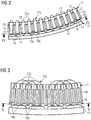
- Figure 3 shows a detailed view of a cross section of the stator 11 and the rotor 12 of a second embodiment of the electric generator 10.
- the embodiment in Figure 3 differentiates itself from the embodiment in Figure 2 , for comprising a different electric circuit 17b.
- the electric circuit 17b comprises plurality of coil distributed windings 19b inside the slots 16 of the stator body 13 and a plurality of end-windings 21b connecting the distributed windings 19b.
- One coil distributed winding 19b is housed inside each of the slots 16.
- Each end-winding 21b connects the axial ends of two distributed windings 19b in two respective circumferentially distanced slots 16.
- each end-winding 21b of one phase connects the axial ends of two distributed windings 19b in two respective circumferentially slots 16, circumferentially separated from each other by three stator teeth and by two slots respectively housing two distributed windings 19b of the other two phases.
- Figure 4 shows a circumferential view, according to the sectional line IV-IV of figure 2 , of the stator 11 and of the electric circuit 17a of the first embodiment of the electric magnet generator 10.
- figure 4 shows the stator 11 and of the electric circuit 17a viewed according to a radial direction oriented from the rotor 12 towards the the rotational axis Y.
- the stator body 13 extends axially between a first axial end portion 21 and a second axial end portion 22.
- An axial middle portion 23 is interposed between the first axial end portion 21 and the second axial end portion 22.
- Each of the teeth 15 extends axially from one to the other of the first axial end portion 21 and the second axial end portion 22 and has a circumferential width S1, S2, which varies along the longitudinal axis Y.
- the circumferential width S1 at the axial middle portion 23 of the stator body 13 is greater than the circumferential width S2 at one of both of the first axial end portion 21 and the second axial end portion 22, in order that such shape of the stator 11 guides and support the end-windings 21a connecting the concentrated end-windings 19a, thus avoiding or at least limiting the length of copper in air.
- the circumferential width S1, S2 of each of the plurality of teeth 15 varies along the longitudinal axis Y gradually between a respective first value S1 at the axial middle portion 23 and a second value S2 of the circumferential width at the first axial end portion 21 and/or at the second axial end portion 22.
- the first axial end portion 21 and the second axial end portion 22 have a U-shaped profile in the circumferential view of Figure 4 .
- the stator body 13 is manufactured as a stack of laminations 130, each lamination 130 having plurality of respective lamination teeth 150 circumferentially distributed around a longitudinal axis Y of the stator 11 and extending axially from one to the other of the first axial end portion 21 and the second axial end portion 22.
- a circumferential width S1, S2 of the lamination teeth 150 varies along the longitudinal axis Y.
- the circumferential width S1 of the lamination teeth 150 at the axial middle portion 23 is greater than the circumferential width S2 at one of both of the first axial end portion 21 and the second axial end portion 22.
- the stacking of the laminations 130 permits to obtain the stator body 13 according to the present invention.
- Figure 5 shows a circumferential view, according to the sectional line V-V of figure 3 , of the stator 11 and of the electric circuit 17b of the second embodiment of the electric magnet generator 10.
- the structure of the stator body 13 is identical.
- the shape of the stator 11 guides and support the end-windings 21b connecting the distributed end-windings 19b, thus avoiding or at least limiting the length of copper in air.
- Figures 6 and 7 shows two circumferential views, respectively equivalent to those of Figures 4 and 5 , of a stator 110 of a permanent magnet electric generator according to the prior art.
- the circumferential width of the teeth is constant. Due to the minimum bending radius of the wire free areas 111a, 111b are respectively comprised between the axial ends of the stator body and the end-windings 210a, 210b of the stator 110.
- the end-windings 210a, 210b are completely in air, thus causing a magnetic circuit with reduced characteristics, which the present invention permits avoiding or limiting.
Landscapes
- Engineering & Computer Science (AREA)
- Power Engineering (AREA)
- Life Sciences & Earth Sciences (AREA)
- Sustainable Energy (AREA)
- Sustainable Development (AREA)
- Windings For Motors And Generators (AREA)
- Iron Core Of Rotating Electric Machines (AREA)
Priority Applications (1)
| Application Number | Priority Date | Filing Date | Title |
|---|---|---|---|
| EP17205944.6A EP3496233A1 (fr) | 2017-12-07 | 2017-12-07 | Générateur électrique présentant des têtes de bobines à saillie axiale réduite |
Applications Claiming Priority (1)
| Application Number | Priority Date | Filing Date | Title |
|---|---|---|---|
| EP17205944.6A EP3496233A1 (fr) | 2017-12-07 | 2017-12-07 | Générateur électrique présentant des têtes de bobines à saillie axiale réduite |
Publications (1)
| Publication Number | Publication Date |
|---|---|
| EP3496233A1 true EP3496233A1 (fr) | 2019-06-12 |
Family
ID=60627563
Family Applications (1)
| Application Number | Title | Priority Date | Filing Date |
|---|---|---|---|
| EP17205944.6A Withdrawn EP3496233A1 (fr) | 2017-12-07 | 2017-12-07 | Générateur électrique présentant des têtes de bobines à saillie axiale réduite |
Country Status (1)
| Country | Link |
|---|---|
| EP (1) | EP3496233A1 (fr) |
Citations (6)
| Publication number | Priority date | Publication date | Assignee | Title |
|---|---|---|---|---|
| JPS5849053A (ja) * | 1981-09-16 | 1983-03-23 | Toshiba Corp | 電動機の固定子鉄心 |
| JP2003009433A (ja) * | 2001-06-22 | 2003-01-10 | Hitachi Ltd | 回転電機 |
| JP2010124577A (ja) * | 2008-11-19 | 2010-06-03 | Denso Corp | モータ |
| DE102013201861B3 (de) * | 2013-02-05 | 2014-07-17 | Siemens Aktiengesellschaft | Polelement für einen Rotor eines Synchrongenerators |
| US20150084476A1 (en) * | 2013-09-23 | 2015-03-26 | New Motech Co., Ltd. | Laminated core of motor having structure suitable for insulation coating |
| EP3200319A1 (fr) * | 2016-01-29 | 2017-08-02 | Zhejiang Sanhua Automotive Components Co., Ltd. | Ensemble de stator et moteur et pompe électrique le comprenant |
-
2017
- 2017-12-07 EP EP17205944.6A patent/EP3496233A1/fr not_active Withdrawn
Patent Citations (6)
| Publication number | Priority date | Publication date | Assignee | Title |
|---|---|---|---|---|
| JPS5849053A (ja) * | 1981-09-16 | 1983-03-23 | Toshiba Corp | 電動機の固定子鉄心 |
| JP2003009433A (ja) * | 2001-06-22 | 2003-01-10 | Hitachi Ltd | 回転電機 |
| JP2010124577A (ja) * | 2008-11-19 | 2010-06-03 | Denso Corp | モータ |
| DE102013201861B3 (de) * | 2013-02-05 | 2014-07-17 | Siemens Aktiengesellschaft | Polelement für einen Rotor eines Synchrongenerators |
| US20150084476A1 (en) * | 2013-09-23 | 2015-03-26 | New Motech Co., Ltd. | Laminated core of motor having structure suitable for insulation coating |
| EP3200319A1 (fr) * | 2016-01-29 | 2017-08-02 | Zhejiang Sanhua Automotive Components Co., Ltd. | Ensemble de stator et moteur et pompe électrique le comprenant |
Similar Documents
| Publication | Publication Date | Title |
|---|---|---|
| EP3648305B1 (fr) | Machine électrique ayant une conception de dent hybride | |
| US20110025165A1 (en) | Rotating electrical machine | |
| EP2493056B1 (fr) | Machine électrique, en particulier un générateur électrique | |
| JP4940252B2 (ja) | 回転電機の製造方法 | |
| JP5695748B2 (ja) | 回転電機 | |
| US11909260B2 (en) | Coil formation in an electric machine with concentrated windings | |
| US11043867B2 (en) | Cooling of the end-windings of an electric generator | |
| EP4102683A1 (fr) | Refroidissement d'un générateur électrique | |
| EP3560075A1 (fr) | Machine électrique à stator segmenté | |
| EP3514922B1 (fr) | Machine électrique munie d'enroulements multiples a nombre fractionnaire d'encoches par pôle et phase | |
| EP3509188B1 (fr) | Générateur électrique comprenant une plaque d'extrémité de stator | |
| EP3496233A1 (fr) | Générateur électrique présentant des têtes de bobines à saillie axiale réduite | |
| US9843247B2 (en) | Rotating electric machine | |
| EP3811496B1 (fr) | Machine électrique comportant un stator | |
| US20210242740A1 (en) | Concentrated winding layout for a stator of an electrical ac machine | |
| EP4092885A1 (fr) | Refroidissement au niveau des extrémités axiales d'un générateur électrique | |
| EP4009493A1 (fr) | Générateur électrique comprenant un stator doté d'une plaque d'extrémité | |
| EP4087090A1 (fr) | Machine électrique, élément d'extension de stator et éolienne | |
| EP3989399A1 (fr) | Segment de stator ou de rotor comprenant des bobines sur des dents ancrant le bord extérieur de la bobine avec un adhésif | |
| EP3703224B1 (fr) | Procédé de fabrication d'un stator ou d'un rotor segmenté d'une machine électrique | |
| EP3934059A1 (fr) | Machine électrique comportant un stator ou un rotor segmenté | |
| CN102468732A (zh) | 一种低损耗的低速永磁同步电机 |
Legal Events
| Date | Code | Title | Description |
|---|---|---|---|
| PUAI | Public reference made under article 153(3) epc to a published international application that has entered the european phase |
Free format text: ORIGINAL CODE: 0009012 |
|
| AK | Designated contracting states |
Kind code of ref document: A1 Designated state(s): AL AT BE BG CH CY CZ DE DK EE ES FI FR GB GR HR HU IE IS IT LI LT LU LV MC MK MT NL NO PL PT RO RS SE SI SK SM TR |
|
| AX | Request for extension of the european patent |
Extension state: BA ME |
|
| STAA | Information on the status of an ep patent application or granted ep patent |
Free format text: STATUS: THE APPLICATION IS DEEMED TO BE WITHDRAWN |
|
| 18D | Application deemed to be withdrawn |
Effective date: 20191213 |