EP3496218B1 - Anschlussvorrichtung eines beweglichen schlittens mit einem elektrischen gerät an eine zelle mit mittlerer oder hoher spannung, und zelle, die eine solche vorrichtung umfasst - Google Patents
Anschlussvorrichtung eines beweglichen schlittens mit einem elektrischen gerät an eine zelle mit mittlerer oder hoher spannung, und zelle, die eine solche vorrichtung umfasst Download PDFInfo
- Publication number
- EP3496218B1 EP3496218B1 EP18204487.5A EP18204487A EP3496218B1 EP 3496218 B1 EP3496218 B1 EP 3496218B1 EP 18204487 A EP18204487 A EP 18204487A EP 3496218 B1 EP3496218 B1 EP 3496218B1
- Authority
- EP
- European Patent Office
- Prior art keywords
- cell
- aforementioned
- nut
- termed
- connectors
- Prior art date
- Legal status (The legal status is an assumption and is not a legal conclusion. Google has not performed a legal analysis and makes no representation as to the accuracy of the status listed.)
- Active
Links
Images


Classifications
-
- H—ELECTRICITY
- H02—GENERATION; CONVERSION OR DISTRIBUTION OF ELECTRIC POWER
- H02B—BOARDS, SUBSTATIONS OR SWITCHING ARRANGEMENTS FOR THE SUPPLY OR DISTRIBUTION OF ELECTRIC POWER
- H02B11/00—Switchgear having carriage withdrawable for isolation
- H02B11/12—Switchgear having carriage withdrawable for isolation with isolation by horizontal withdrawal
- H02B11/127—Withdrawal mechanism
- H02B11/133—Withdrawal mechanism with interlock
-
- H—ELECTRICITY
- H05—ELECTRIC TECHNIQUES NOT OTHERWISE PROVIDED FOR
- H05K—PRINTED CIRCUITS; CASINGS OR CONSTRUCTIONAL DETAILS OF ELECTRIC APPARATUS; MANUFACTURE OF ASSEMBLAGES OF ELECTRICAL COMPONENTS
- H05K7/00—Constructional details common to different types of electric apparatus
- H05K7/14—Mounting supporting structure in casing or on frame or rack
- H05K7/1401—Mounting supporting structure in casing or on frame or rack comprising clamping or extracting means
- H05K7/1411—Mounting supporting structure in casing or on frame or rack comprising clamping or extracting means for securing or extracting box-type drawers
-
- H—ELECTRICITY
- H05—ELECTRIC TECHNIQUES NOT OTHERWISE PROVIDED FOR
- H05K—PRINTED CIRCUITS; CASINGS OR CONSTRUCTIONAL DETAILS OF ELECTRIC APPARATUS; MANUFACTURE OF ASSEMBLAGES OF ELECTRICAL COMPONENTS
- H05K7/00—Constructional details common to different types of electric apparatus
- H05K7/14—Mounting supporting structure in casing or on frame or rack
- H05K7/1438—Back panels or connecting means therefor; Terminals; Coding means to avoid wrong insertion
-
- H—ELECTRICITY
- H02—GENERATION; CONVERSION OR DISTRIBUTION OF ELECTRIC POWER
- H02B—BOARDS, SUBSTATIONS OR SWITCHING ARRANGEMENTS FOR THE SUPPLY OR DISTRIBUTION OF ELECTRIC POWER
- H02B11/00—Switchgear having carriage withdrawable for isolation
- H02B11/02—Details
- H02B11/10—Indicating electrical condition of gear; Arrangement of test sockets
Definitions
- the present invention relates to a device for mechanical and electrical connection of a mobile carriage carrying electrical equipment to a medium or high voltage cell, said connection device comprising a drive nut belonging to the aforementioned cell capable of cooperating with a hook belonging to to the aforementioned carriage to drive the carriage to a position of plugging in the equipment to the cell, an electrical auxiliary connector of the cell capable of cooperating with a complementary electrical auxiliary connector of the mobile carriage.
- the term “electrical equipment” used interchangeably includes any device such as switch, circuit breaker, contactor, disconnector, fuse switch, recloser, etc.
- the invention is particularly suitable for driving and monitoring high voltage electrical networks, that is to say a voltage greater than 1000V.
- a high voltage electrical switchgear cell usually has a metal structure with several distinct compartments. There can be found a so-called “busbar” compartment placed for example at the rear of the cubicle and where the conductive metal bars of the electrical network are grouped together, a so-called “switchgear” compartment which includes a switch device, which can be mounted. on a mobile carriage so as to be withdrawable, that is to say disconnectable from the busbar, a compartment called “cables" for the cable connection part and which generally includes the sensors for current / voltage measurements, and a compartment usually called “low voltage” box which includes the protection and control system of the switch device with in particular one or more protection and control relays.
- equipment compartment in which the carriage and the electrical apparatus are located, are also housed motorized drive means of the mobile carriage, which means are intended to move the mobile carriage between a plugged-in position, in which the pins are respectively connected to the upstream and downstream bars of the switchgear cubicle, and a withdrawn position, in which the pins are disconnected from the bars.
- drive means comprise a drive motor which for example turns an endless screw on which a nut is mounted, as well as means for attaching the carriage to the nut so as to allow it to be driven by the aforementioned means.
- Such a cell also comprises auxiliary connectors capable of being electrically connected to complementary auxiliary connectors of the carriage, these auxiliaries being intended to ensure the electrical and computer connections between the cell and the switching device.
- auxiliaries can be, for example, power connectors for supplying the triggering / closing coils and conveying the information of the open or closed position of the device by means of a connection with the protection relay.
- the present invention solves these problems and proposes a device for the mechanical and electrical connection of an electrical apparatus mounted on a mobile carriage to a medium voltage cell, this device making it possible to considerably reduce the number of interlockings required for the implementation of this connection while ensuring a constant quality of contact between the connectors throughout the movement of the apparatus, from its test position to the plugged-in position, whether in the direction of plugging-in or else of unplugging.
- connection device according to claim 1.
- these so-called first means comprise the aforementioned hook mounted articulated with respect to a support of the mobile carriage and comprising a notch able to cooperate with the aforementioned nut, said hook being suitable during the insertion of the carriage, to come. abutting on the nut, then turning counterclockwise against the return means, before being returned to the hooked position on the nut by the return means, then rotating in the direction hourly.
- this device comprises so-called third means, for mechanically connecting the auxiliary electrical connector of the cell to the aforementioned nut, in such a way that this connector follows the movement of the mobile carriage after the mechanical connection of the carriage to the cell carried out, throughout the movement between the test position corresponding to the position hooked up by the carriage to the cell, and the plugged-in position.
- these so-called third means comprise means for ensuring the contact pressure between the two connectors.
- the support of the cell auxiliary connector is slidably mounted along a slideway belonging to the cell.
- the aforementioned lever is mounted articulated on the one hand, with respect to the nut, and on the other hand, with respect to the support of the aforementioned cell auxiliary connector.
- these so-called third means further comprise a spring interposed between a part belonging to the lever and the support of the aforementioned auxiliary connector, said spring being able to exert a contact pressure between the two connectors in the electrically connected position of these two connectors.
- these compensation means comprise a so-called first slot provided at one of the ends of the aforementioned lever and able to cooperate with the nut then, also provided in the lever between the axis of articulation of the lever to the support. and a point of attachment of the aforementioned spring to the lever, a so-called second slot, able to cooperate with a stud of the support, these two slots and the spring cooperating with the nut and the support in such a way that, during an additional stroke of the switchgear after connecting the aforementioned connectors, this travel being necessary so that the hook comes to lock on the nut, the support moves on the slide, causing the rotation of the lever relative to the support in the anti-clockwise direction by means of the two aforementioned slots, this causing a traction of the spring, this traction of the spring, in combination with the movement of the lever relative to the stud and the aforementioned nut, by means of the two aforementioned slots, making it possible to obtain compensation for the dimensional variations of the connectors.
- the aforementioned connectors are intended to ensure the electrical and computer connections between the cell and the equipment.
- these connectors include eight power connectors intended to supply the tripping / interlocking coils and to convey the information of the open or closed position of the contacts of the apparatus, or else a contactor of the RJ 45 type, intended to connect a PLC belonging to the carriage to a PLC belonging to the cell.
- the aforementioned drive nut is mounted on the worm of a drive motor belonging to the mobile carriage.
- a further subject of the present invention is a medium or high voltage switchgear cell, this cell being characterized in that it comprises a connection device comprising the aforementioned characteristics taken alone or in combination.
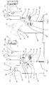
- a high voltage electrical equipment cell part C comprising, housed in a metal structure, several distinct compartments, namely a compartment (j) called “busbar”, located at the rear of the cell and where the conductive metal bars of the electrical network are grouped together, a compartment (a) called “switchgear” intended to include a switch device I mounted on a mobile carriage M, a compartment (c) called “cables” allowing the connection of certain elements of the cell by means of cables and which generally comprises the sensors for current / voltage measurements, and a compartment (t) usually called a "low voltage” box which comprises the protection and control system of the switch device with in particular one or more protection and control relays.
- a compartment (j) called "busbar” located at the rear of the cell and where the conductive metal bars of the electrical network are grouped together
- a compartment (a) called “switchgear” intended to include a switch device I mounted on a mobile carriage M
- a compartment (c) called “cables” allowing the connection of
- this compartment called “equipment” (a) comprises two guide rails 1,2 located at the lower part of the compartment and against the interior faces respectively of the two side walls 3,4 of the cell C, these rails being intended to facilitate insertion of the mobile carriage inside said compartment.
- These drive means comprise a drive motor which for example rotates an endless screw 5 around which a nut 6 is mounted in such a way that the rotation of the screw causes the displacement of the nut.
- This screw is mechanically linked to the carriage M, by means of attachment means intended to cooperate with a stud 6a of the aforementioned nut 6 so as to allow the attachment of the carriage to the aforementioned nut when the carriage is sufficiently introduced into the "switchgear" compartment (a).
- the “equipment” compartment (a) also comprises so-called auxiliary connectors 7 of the cell C capable of being brought into contact with so-called auxiliary connectors 8 of the mobile carriage M, so as to allow the circulation of low voltage or computer signals between carriage M and cubicle C.
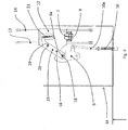
- the connection device comprises, for its part intended to achieve the mechanical connection of the carriage M to the cell C, a hook 9 mounted articulated with respect to a support of the mobile carriage M and returned by a spring 10 in the clockwise in the hooked position with the nut 6, said hook 9 comprising a notch 11 able to cooperate with the nut 6 of the aforementioned screw 5 such that during the movement of insertion of the movable carriage M into the compartment "Apparatus" (a), the hook 9 comes into contact with the nut 6, then turns counterclockwise against the force of the spring 10 until the nut 6 comes into contact with the the aforementioned notch 11 thus achieving the mechanical hooking of the carriage M on the cell C, which corresponds to a so-called test position of the apparatus, this hooking allowing the carriage M to be moved by the aforementioned drive mechanism towards a racking-in position, at the busbar s of the cell.
- this connection device performs, at the same time as the aforementioned mechanical attachment, the electrical connection between the two aforementioned auxiliary connectors 7,8.
- the auxiliary connector 7 of the cell and the auxiliary connector 8 of the carriage are located relative to each other in the cell C and in the carriage M respectively, so that the connection between the two connectors 7,8 is carried out when the carriage M is in the position hooked onto the nut 6, a position called the test position.
- the drive nut 6 is mechanically connected to the auxiliary connector 7 of the cell C, in such a way that, after the hook 9 has been hooked onto the nut 6, this nut 6 simultaneously drives the equipment I and the auxiliary connector 7 of cell C.
- the auxiliary connector 7 of the cell is mounted on a support 12 called the support of the auxiliary connector of the cell C, which support 12 is slidably mounted on a slide formed by two rails 13,14 integral with a support fixed in relation to the cell.
- the aforementioned nut 6 is mechanically connected to the aforementioned support 12 of the auxiliary connector in such a way that the displacement of the mobile carriage M towards the position of the device connected to the busbar, causes the displacement in the same direction of the connector support 12. auxiliary to the cell.
- These mechanical connection means between the nut 6 and the support 12 of the auxiliary connector 7 of the cell comprise a lever 15 mounted articulated on the one hand, around a fixed axis 16 of the auxiliary connector support 12, and mechanically connected. to the nut 6 via an orifice 17 provided in the lever 15 adapted to cooperate with said nut.
- this connection device further comprises so-called compensation means capable of compensating for the dimensional variations of all the parts involved in the connection, so as to ensure a constant quality of contact between the two connectors 7, 8 whatever be these dimensional variations.
- These compensation means comprise a so-called first slot 18 provided in the aforementioned lever 15 constituting the aforementioned orifice 17 capable of cooperate with the stud 6a of the aforementioned nut 6, a so-called second slot 20 provided in the lever 15, and able to cooperate with a stud 19 belonging to the support 12 of the auxiliary connector of the cell, and a spring 21 interposed between an end part 15a of the lever 15 and the support 12 for the auxiliary connector of the cell, this spring being able to be brought into a pulling position when the two connectors 7,8 are in the connected position and the device I in the locked position in the cell by the hook 9, or test position, so as to ensure a constant quality of connection between the two connectors 7,8 independently of the dimensional variations of the connectors, by a rotation of the lever 15 cooperating with the so-called first slots and second 18.20, which slots 18.20 cooperate respectively with the nut 6 and the stud 19.
- connection device The operation of the connection device according to the invention will be described in what follows with reference to the figures.
- the drive nut 6 mounted on the worm 5 of the drive motor of the carriage M can then drive at the same time the device I and the support 12 of the auxiliary connector 7 of the cell, when of the device I connection operation on the busbar.
- the support 12 of the auxiliary connector of the cell is positioned in the cell by the lever 15, the spring 21, the drive nut 6, and the slide 13,14.
- the spring 21 before the connection of the auxiliary connectors 7,8 positions with a certain force the lever 15 on the connector support 12 inside the so-called second lumen 20.
- the force exerted during the connection of the two connectors 7,8 is much lower than the force exerted by the spring 21 at the point of contact of the lever 15 on the connector support 12 inside the so-called second lumen 20 so as to guarantee the connection between the two connectors.
- the device I must perform an additional stroke after connecting the connectors 7,8 so that the hook 9 is moved in rotation until the nut 6 is placed at the bottom of the notch 11 of said hook 9.
- the device I mounted on the carriage M can be driven by the nut 6 mounted on the worm 5 so as to connect the device I to the busbar of the cell.
- the drive nut 6 also drives the connector support 12 via the lever 15, which support 12 slides along the rods 13,14 forming slides.
- the system for attaching the carriage M makes it possible to simultaneously connect the electrical auxiliary connectors 7,8 at the same time when the carriage M is placed in the cell C, this positioning leading to the locking of the carriage. M in cell C.
- a positive contact is obtained between the two connectors, which are not subject to the effects of the inertia of the device when it is inserted, given the presence of the spring which absorbs these effects.
- connection system automatically compensates for dimensional variations of all parts involved in the connection.
- connection system ensures positive contact during the connector connection and disconnection operations throughout the movement between the test or hooked position and the plugged-in position.
- the invention also makes it possible to reduce the efforts required to make the connection and disconnection by the fact that it is the inertia of the electrical equipment which establishes the contact.
- the invention also makes it possible to reduce the number of interlockings which it is necessary to carry out, by the fact that the mechanical connection of the carriage to the cell and the electrical connection of the connectors are no longer carried out manually but automatically.
- the invention also makes it possible to connect the auxiliary connectors automatically, from the switchgear test position, that is to say before racking-in on the busbar, so as to retain the possibility of carrying out all the tests in this position, as we have in the case of manual connection, while keeping the advantages of simplifying an automatic connection.
Landscapes
- Engineering & Computer Science (AREA)
- Microelectronics & Electronic Packaging (AREA)
- Power Engineering (AREA)
- Details Of Connecting Devices For Male And Female Coupling (AREA)
- Trip Switchboards (AREA)
- Current-Collector Devices For Electrically Propelled Vehicles (AREA)
- Electric Propulsion And Braking For Vehicles (AREA)
Claims (11)
- Vorrichtung zum mechanischen und elektrischen Verbinden eines beweglichen Schlittens (M), der eine elektrische Anlage (I) trägt, mit einer Mittel- oder Hochspannungszelle (C), die den beweglichen Schlitten (M) und die Mittel- oder Hochspannungszelle (C) enthält; wobei die Vorrichtung außerdem Folgendes umfasst:- eine Antriebsmutter (6), die zu der Zelle (C) gehört und mit einem Haken (9), der zu dem Schlitten (M) gehört, zusammenwirken kann, um den Schlitten in eine Position zum Einstecken der Anlage des Schlittens (M) in die Zelle (C) anzutreiben,- einen elektrischen Hilfsverbinder (7) der Zelle (C), der mit einem komplementären elektrischen Hilfsverbinder (8) des beweglichen Schlittens (M) zusammenwirken kann,wobei die Vorrichtung erste Mittel enthält, die ermöglichen, das Verankern des Hakens (9) an der Mutter (6) automatisch zu verwirklichen, wenn der Schlitten (M) in die Zelle (C) bis in die Prüfposition, in der die Anlage (I) sich in der Zelle (C) befindet, ohne eingesteckt zu sein, eingesetzt wird, und zweite Mittel enthält, die ermöglichen, gleichzeitig mit dem Verankern die automatische elektrische Verbindung der beiden Verbinder (7, 8) der Zelle (C) bzw. des Schlittens (M) zu verwirklichen, derart, dass nach diesem Verbinden die Verlagerung des Verbinders, der zu der Zelle (C) gehört, von der Verlagerung jenes (8) des beweglichen Schlittens (M) zwischen der Prüfposition und der in die Anlage (I) eingesteckten Position und umgekehrt zwischen der eingesteckten Position und der Prüfposition abhängt,wobei die ersten Mittel den Haken (9) enthalten, der in Bezug auf einen Träger des beweglichen Schlittens (M) gelenkig montiert ist und eine Kehle (11) aufweist, die mit der Mutter (6) zusammenwirken kann, wobei der Haken (9) beim Einführen des Schlittens (M) an der Mutter (6) anschlagen kann und sich dann im Gegenuhrzeigersinn entgegen Rückstellmitteln (10, 10a) drehen kann, bevor er durch die Rückstellmittel in die Einhakposition an der Mutter (6) zurückgeführt wird und anschließend eine Drehung im Uhrzeigersinn ausführt, wobei diese zweiten Mittel darin bestehen, dass die beiden Verbinder (7, 8) relativ zueinander in der Zelle (C) bzw. auf dem Schlitten (M) angeordnet werden, derart, dass diese beiden Verbinder (7, 8) in der verankerten Position des Hakens (9) an der Mutter (6) in die Position einer elektrischen Verbindung gebracht werden,wobei die Vorrichtung dritte Mittel enthält, um den elektrischen Hilfsverbinder (7) der Zelle (C) mit der Mutter (6) mechanisch zu verbinden, derart, dass dieser Verbinder (7) der Bewegung des beweglichen Schlittens (M) nach dem erfolgten mechanischen Verbinden des Schlittens (M) mit der Zelle (C) längs der Verlagerung zwischen der Prüfposition oder der verankerten Position und der eingesteckten Position folgt,wobei diese dritten Mittel einen Hebel (15) enthalten, der zwischen der Antriebsmutter (6) und einem Träger (12) des Hilfsverbinders der Zelle (C) eingefügt ist, derart, dass dann, wenn der Haken (9) des Schlittens (M) an der Antriebsmutter (6) verankert ist, der Hebel (15) den Träger (12) des Hilfsverbinders (7) der Zelle (C) antreibt, wenn der Schlitten (M) verlagert wird, und dass der Träger (12) des Hilfsverbinders (7) der Zelle (C) längs einer Gleitstange (13, 14), die zu der Zelle (C) gehört, gleitend montiert ist.
- Verbindungvorrichtung nach Anspruch 1, wobei diese dritten Mittel Mittel enthalten, um den Kontaktdruck zwischen den beiden Verbindern (7, 8) sicherzustellen.
- Verbindungvorrichtung nach Anspruch 1 oder 2, die vierte Ausgleichsmittel enthält, die die Abmessungsschwankungen sämtlicher an der Verbindung beteiligten Teile ausgleichen können, derart, dass zwischen den beiden Verbindern (7, 8) eine konstante Kontaktqualität sichergestellt ist.
- Verbindungvorrichtung nach Anspruch 3, wobei die dritten Mittel die vierten Ausgleichsmittel enthalten.
- Verbindungsvorrichtung nach Anspruch 1, wobei der Hebel (15) einerseits in Bezug auf die Mutter (6) und andererseits in Bezug auf den Träger (12) des Hilfsverbinders (7) der Zelle (C) gelenkig montiert ist.
- Verbindungvorrichtung nach Anspruch 1 oder 5, wobei die dritten Mittel außerdem eine Feder (21) enthalten, die zwischen einem Teil (15a), der zu dem Hebel (15) gehört, und dem Träger (12) des Hilfsverbinders (7) eingefügt ist, wobei die Feder (21) zwischen den beiden Verbindern (7, 8) in der Position einer elektrischen Verbindung dieser beiden Verbinder einen Kontaktdruck ausüben kann.
- Verbindungsvorrichtung nach Anspruch 6, wobei die Ausgleichsmittel ein erstes Langloch (18), das an einem der Enden des Hebels (15) vorgesehen ist und mit der Mutter (6) zusammenwirken kann und außerdem in dem Hebel (15) zwischen der Anlenkungsachse (16) des Hebels (15) am Träger (12) und einem Befestigungspunkt der Feder (21) am Hebel (15) vorgesehen ist, und ein zweites Langloch (20), das mit einer Kontaktstelle (9) des Trägers (12) zusammenwirken kann, aufweisen, wobei diese beiden Langlöcher (18, 20) und die Feder (21) mit der Mutter (6) und dem Träger (12) in der Weise zusammenwirken, dass auf einem zusätzlichen Weg der Anlage (I) nach dem Verbinden der Verbinder (7, 8), wobei dieser Weg notwendig ist, damit der Haken (9) an der Mutter (6) blockiert wird, der Träger (12) sich längs der Gleitstange (13, 14) verlagert und dabei die Drehung des Hebels (15) in Bezug auf den Träger (12) im Gegenuhrzeigersinn über die beiden Langlöcher (18, 20) antreibt, wodurch ein Auseinanderziehen der Feder (21) bewirkt wird, wobei diese Auseinanderziehen der Feder in Kombination mit der Verlagerung des Hebels (15) in Bezug auf die Kontaktstelle (9) und die Mutter (6) über die beiden Langlöcher (18, 20) ermöglicht, einen Ausgleich der Abmessungsschwankungen der Verbinder (7, 8) zu erhalten.
- Verbindungsvorrichtung nach einem der vorhergehenden Ansprüche, wobei die Verbinder (7, 8) dazu bestimmt sind, die elektrischen und datentechnischen Verbindungen zwischen der Zelle (C) und der Anlage (I) sicherzustellen.
- Verbindungsvorrichtung nach Anspruch 8, wobei diese Verbinder acht Leistungsverbinder, die dazu bestimmt sind, die Auskupplungs/Einkupplungs-Spulen zu speisen und Informationen über die geöffnete oder geschlossene Position der Kontakte der Anlage zu transportieren, oder ein Stecker des Typs RJ 45, der dazu bestimmt ist, einen Automaten, der zu dem Schlitten gehört, mit einem Automaten, der zu der Zelle gehört, zu verbinden, umfassen.
- Verbindungsvorrichtung nach einem der vorhergehenden Ansprüche, wobei die Antriebsmutter (6) an der Endlosschraube (5) eines Antriebsmotors, der zu dem beweglichen Schlitten (M) gehört, montiert ist.
- Mittel- oder Hochspannungs-Zelle für Anlagen, die eine Verbindungsvorrichtung nach einem der vorhergehenden Ansprüche enthält.
Applications Claiming Priority (1)
| Application Number | Priority Date | Filing Date | Title |
|---|---|---|---|
| FR1761766A FR3074974B1 (fr) | 2017-12-07 | 2017-12-07 | Dispositif de raccordement d'un chariot mobile portant un appareillage electrique a une cellule moyenne ou haute tension, et cellule comportant un tel dispositif. |
Publications (2)
| Publication Number | Publication Date |
|---|---|
| EP3496218A1 EP3496218A1 (de) | 2019-06-12 |
| EP3496218B1 true EP3496218B1 (de) | 2022-01-05 |
Family
ID=62528479
Family Applications (1)
| Application Number | Title | Priority Date | Filing Date |
|---|---|---|---|
| EP18204487.5A Active EP3496218B1 (de) | 2017-12-07 | 2018-11-06 | Anschlussvorrichtung eines beweglichen schlittens mit einem elektrischen gerät an eine zelle mit mittlerer oder hoher spannung, und zelle, die eine solche vorrichtung umfasst |
Country Status (3)
| Country | Link |
|---|---|
| EP (1) | EP3496218B1 (de) |
| CN (1) | CN110035633B (de) |
| FR (1) | FR3074974B1 (de) |
Families Citing this family (1)
| Publication number | Priority date | Publication date | Assignee | Title |
|---|---|---|---|---|
| CN116184233B (zh) * | 2023-03-27 | 2023-09-15 | 安可捷检测(常州)有限公司 | 一种便于装夹的电芯充放电测试装置 |
Family Cites Families (6)
| Publication number | Priority date | Publication date | Assignee | Title |
|---|---|---|---|---|
| FR2594265B1 (fr) * | 1986-02-10 | 1988-04-15 | Merlin Gerin | Mecanisme d'embrochage et de debrochage d'un disjoncteur electrique avec circuits principaux et auxiliaires. |
| DE3766385D1 (de) * | 1986-02-10 | 1991-01-10 | Merlin Gerin | Mechanismus zum schnappen und trennen eines elektrischen schalters mit haupt- und hilfsschaltkreisen. |
| US5434369A (en) * | 1994-02-14 | 1995-07-18 | Abb Power T & D Company, Inc. | Automated secondary disconnect mechanism for electrical switchgear |
| FR2782579B1 (fr) * | 1998-08-24 | 2000-10-06 | Schneider Electric Ind Sa | Appareillage electrique de coupure comportant un disjoncteur embrochable et un dispositif indiquant l'etat du disjoncteur |
| CN103234811B (zh) * | 2013-04-27 | 2016-09-14 | 甘肃蓝科石化高新装备股份有限公司 | 水压试验机管长无极适应旋移装置 |
| GB201317263D0 (en) * | 2013-09-30 | 2013-11-13 | Eaton Ind Netherlands Bv | Switching gear |
-
2017
- 2017-12-07 FR FR1761766A patent/FR3074974B1/fr not_active Expired - Fee Related
-
2018
- 2018-11-06 EP EP18204487.5A patent/EP3496218B1/de active Active
- 2018-12-04 CN CN201811476668.8A patent/CN110035633B/zh active Active
Non-Patent Citations (1)
| Title |
|---|
| None * |
Also Published As
| Publication number | Publication date |
|---|---|
| FR3074974B1 (fr) | 2020-07-17 |
| CN110035633A (zh) | 2019-07-19 |
| EP3496218A1 (de) | 2019-06-12 |
| FR3074974A1 (fr) | 2019-06-14 |
| CN110035633B (zh) | 2022-05-13 |
Similar Documents
| Publication | Publication Date | Title |
|---|---|---|
| EP0236179B1 (de) | Mechanismus zum Schnappen und Trennen eines elektrischen Schalters mit Haupt- und Hilfsschaltkreisen | |
| EP0567415B1 (de) | Trennbarer Schalter mit Isolierstoffgehäuse | |
| EP0567416B1 (de) | Mechanische Verriegelungsvorrichtung von zwei Schaltern mit Isolierstoff-Formgehäuse | |
| EP0320412B1 (de) | Mehrpoliger Schalter für höheren Strombereich bestehend aus zwei verbundenen formgepressten Gehäusen | |
| EP2936534B1 (de) | Modulare elektrische schaltvorrichtung mit mindestens einer einpoligen absperreinheit und schalteranordnung mit solchen vorrichtungen | |
| EP3496218B1 (de) | Anschlussvorrichtung eines beweglichen schlittens mit einem elektrischen gerät an eine zelle mit mittlerer oder hoher spannung, und zelle, die eine solche vorrichtung umfasst | |
| EP0264318A1 (de) | Elektromagnetisches Schaltgerät mit auswechselbaren Schaltern | |
| FR2782579A1 (fr) | Appareillage electrique de coupure comportant un disjoncteur embrochable et un dispositif indiquant l'etat du disjoncteur | |
| EP0381542B1 (de) | Geschütztes Wendeschütz mit einem Mehrzweckübertragungssystem für die Steuerung von Bestätigungsschaltern | |
| WO2017098121A1 (fr) | Meuble electrique a disjoncteurs montes dans la porte | |
| WO1992006483A1 (fr) | Dispositif de commutation comprenant un interrupteur auxiliaire a fonctionnement monostable couple a un interrupteur principal | |
| EP0511042B1 (de) | Elektromechanisches Schaltgerät mit frontalem Zusatzbauteil | |
| EP0589780B1 (de) | Trennvorrichtung kombinierbar mit einem Lastschalter | |
| CA2364235A1 (fr) | Dispositif de securite applique a l'embrochage et au debrochage d'un fusible dans un appareillage electrique moyenne tension | |
| WO2010040713A1 (fr) | Dispositif et procede de protection d'une liaison d'un reseau electrique moyenne, haute ou tres haute tension | |
| FR3058828A1 (fr) | Selecteur de fonctionnement d'un sectionneur de mise a la terre | |
| FR2796768A1 (fr) | Dispositif de connexion d'auxiliaire pour un appareillage electrique de coupure debrochable | |
| FR2594266A1 (fr) | Mecanisme d'embrochage et de debrochage d'un disjoncteur electrique a systeme de blocage du support mecanique mobile. | |
| FR2594265A1 (fr) | Mecanisme d'embrochage et de debrochage d'un disjoncteur electrique avec circuits principaux et auxiliaires. | |
| FR2960976A1 (fr) | Dispositif pour realiser un test dielectrique de cables par injection d'une tension sur ledit cable dans un appareillage electrique et cellule electrique comportant un tel dispositif | |
| EP3116005B1 (de) | Abnehmbares modul von einem sockel für die strommessung in einem stromnetz | |
| EP4256662B1 (de) | Einschub für schaltgerät und baugruppe beinhaltend einen solchen einschub und ein solches schaltgerät | |
| EP3349306B1 (de) | Modular elektrisches gerät | |
| FR2535521A1 (fr) | Disjoncteur a sectionnement de neutre | |
| FR2542142A1 (fr) | Interrupteur ou disjoncteur a pinces d'embrochage perfectionnees |
Legal Events
| Date | Code | Title | Description |
|---|---|---|---|
| PUAI | Public reference made under article 153(3) epc to a published international application that has entered the european phase |
Free format text: ORIGINAL CODE: 0009012 |
|
| STAA | Information on the status of an ep patent application or granted ep patent |
Free format text: STATUS: THE APPLICATION HAS BEEN PUBLISHED |
|
| AK | Designated contracting states |
Kind code of ref document: A1 Designated state(s): AL AT BE BG CH CY CZ DE DK EE ES FI FR GB GR HR HU IE IS IT LI LT LU LV MC MK MT NL NO PL PT RO RS SE SI SK SM TR |
|
| AX | Request for extension of the european patent |
Extension state: BA ME |
|
| STAA | Information on the status of an ep patent application or granted ep patent |
Free format text: STATUS: REQUEST FOR EXAMINATION WAS MADE |
|
| 17P | Request for examination filed |
Effective date: 20190621 |
|
| RBV | Designated contracting states (corrected) |
Designated state(s): AL AT BE BG CH CY CZ DE DK EE ES FI FR GB GR HR HU IE IS IT LI LT LU LV MC MK MT NL NO PL PT RO RS SE SI SK SM TR |
|
| STAA | Information on the status of an ep patent application or granted ep patent |
Free format text: STATUS: EXAMINATION IS IN PROGRESS |
|
| 17Q | First examination report despatched |
Effective date: 20200527 |
|
| GRAP | Despatch of communication of intention to grant a patent |
Free format text: ORIGINAL CODE: EPIDOSNIGR1 |
|
| STAA | Information on the status of an ep patent application or granted ep patent |
Free format text: STATUS: GRANT OF PATENT IS INTENDED |
|
| GRAS | Grant fee paid |
Free format text: ORIGINAL CODE: EPIDOSNIGR3 |
|
| INTG | Intention to grant announced |
Effective date: 20211028 |
|
| GRAA | (expected) grant |
Free format text: ORIGINAL CODE: 0009210 |
|
| STAA | Information on the status of an ep patent application or granted ep patent |
Free format text: STATUS: THE PATENT HAS BEEN GRANTED |
|
| AK | Designated contracting states |
Kind code of ref document: B1 Designated state(s): AL AT BE BG CH CY CZ DE DK EE ES FI FR GB GR HR HU IE IS IT LI LT LU LV MC MK MT NL NO PL PT RO RS SE SI SK SM TR |
|
| REG | Reference to a national code |
Ref country code: GB Ref legal event code: FG4D Free format text: NOT ENGLISH |
|
| REG | Reference to a national code |
Ref country code: CH Ref legal event code: EP |
|
| REG | Reference to a national code |
Ref country code: AT Ref legal event code: REF Ref document number: 1461428 Country of ref document: AT Kind code of ref document: T Effective date: 20220115 |
|
| REG | Reference to a national code |
Ref country code: DE Ref legal event code: R096 Ref document number: 602018029042 Country of ref document: DE |
|
| REG | Reference to a national code |
Ref country code: IE Ref legal event code: FG4D Free format text: LANGUAGE OF EP DOCUMENT: FRENCH |
|
| REG | Reference to a national code |
Ref country code: LT Ref legal event code: MG9D |
|
| REG | Reference to a national code |
Ref country code: NL Ref legal event code: MP Effective date: 20220105 |
|
| REG | Reference to a national code |
Ref country code: AT Ref legal event code: MK05 Ref document number: 1461428 Country of ref document: AT Kind code of ref document: T Effective date: 20220105 |
|
| PG25 | Lapsed in a contracting state [announced via postgrant information from national office to epo] |
Ref country code: NL Free format text: LAPSE BECAUSE OF FAILURE TO SUBMIT A TRANSLATION OF THE DESCRIPTION OR TO PAY THE FEE WITHIN THE PRESCRIBED TIME-LIMIT Effective date: 20220105 |
|
| PG25 | Lapsed in a contracting state [announced via postgrant information from national office to epo] |
Ref country code: SE Free format text: LAPSE BECAUSE OF FAILURE TO SUBMIT A TRANSLATION OF THE DESCRIPTION OR TO PAY THE FEE WITHIN THE PRESCRIBED TIME-LIMIT Effective date: 20220105 Ref country code: RS Free format text: LAPSE BECAUSE OF FAILURE TO SUBMIT A TRANSLATION OF THE DESCRIPTION OR TO PAY THE FEE WITHIN THE PRESCRIBED TIME-LIMIT Effective date: 20220105 Ref country code: PT Free format text: LAPSE BECAUSE OF FAILURE TO SUBMIT A TRANSLATION OF THE DESCRIPTION OR TO PAY THE FEE WITHIN THE PRESCRIBED TIME-LIMIT Effective date: 20220505 Ref country code: NO Free format text: LAPSE BECAUSE OF FAILURE TO SUBMIT A TRANSLATION OF THE DESCRIPTION OR TO PAY THE FEE WITHIN THE PRESCRIBED TIME-LIMIT Effective date: 20220405 Ref country code: LT Free format text: LAPSE BECAUSE OF FAILURE TO SUBMIT A TRANSLATION OF THE DESCRIPTION OR TO PAY THE FEE WITHIN THE PRESCRIBED TIME-LIMIT Effective date: 20220105 Ref country code: HR Free format text: LAPSE BECAUSE OF FAILURE TO SUBMIT A TRANSLATION OF THE DESCRIPTION OR TO PAY THE FEE WITHIN THE PRESCRIBED TIME-LIMIT Effective date: 20220105 Ref country code: ES Free format text: LAPSE BECAUSE OF FAILURE TO SUBMIT A TRANSLATION OF THE DESCRIPTION OR TO PAY THE FEE WITHIN THE PRESCRIBED TIME-LIMIT Effective date: 20220105 Ref country code: BG Free format text: LAPSE BECAUSE OF FAILURE TO SUBMIT A TRANSLATION OF THE DESCRIPTION OR TO PAY THE FEE WITHIN THE PRESCRIBED TIME-LIMIT Effective date: 20220405 |
|
| PG25 | Lapsed in a contracting state [announced via postgrant information from national office to epo] |
Ref country code: PL Free format text: LAPSE BECAUSE OF FAILURE TO SUBMIT A TRANSLATION OF THE DESCRIPTION OR TO PAY THE FEE WITHIN THE PRESCRIBED TIME-LIMIT Effective date: 20220105 Ref country code: LV Free format text: LAPSE BECAUSE OF FAILURE TO SUBMIT A TRANSLATION OF THE DESCRIPTION OR TO PAY THE FEE WITHIN THE PRESCRIBED TIME-LIMIT Effective date: 20220105 Ref country code: GR Free format text: LAPSE BECAUSE OF FAILURE TO SUBMIT A TRANSLATION OF THE DESCRIPTION OR TO PAY THE FEE WITHIN THE PRESCRIBED TIME-LIMIT Effective date: 20220406 Ref country code: FI Free format text: LAPSE BECAUSE OF FAILURE TO SUBMIT A TRANSLATION OF THE DESCRIPTION OR TO PAY THE FEE WITHIN THE PRESCRIBED TIME-LIMIT Effective date: 20220105 Ref country code: AT Free format text: LAPSE BECAUSE OF FAILURE TO SUBMIT A TRANSLATION OF THE DESCRIPTION OR TO PAY THE FEE WITHIN THE PRESCRIBED TIME-LIMIT Effective date: 20220105 |
|
| PG25 | Lapsed in a contracting state [announced via postgrant information from national office to epo] |
Ref country code: IS Free format text: LAPSE BECAUSE OF FAILURE TO SUBMIT A TRANSLATION OF THE DESCRIPTION OR TO PAY THE FEE WITHIN THE PRESCRIBED TIME-LIMIT Effective date: 20220505 |
|
| REG | Reference to a national code |
Ref country code: DE Ref legal event code: R097 Ref document number: 602018029042 Country of ref document: DE |
|
| PG25 | Lapsed in a contracting state [announced via postgrant information from national office to epo] |
Ref country code: SM Free format text: LAPSE BECAUSE OF FAILURE TO SUBMIT A TRANSLATION OF THE DESCRIPTION OR TO PAY THE FEE WITHIN THE PRESCRIBED TIME-LIMIT Effective date: 20220105 Ref country code: SK Free format text: LAPSE BECAUSE OF FAILURE TO SUBMIT A TRANSLATION OF THE DESCRIPTION OR TO PAY THE FEE WITHIN THE PRESCRIBED TIME-LIMIT Effective date: 20220105 Ref country code: RO Free format text: LAPSE BECAUSE OF FAILURE TO SUBMIT A TRANSLATION OF THE DESCRIPTION OR TO PAY THE FEE WITHIN THE PRESCRIBED TIME-LIMIT Effective date: 20220105 Ref country code: EE Free format text: LAPSE BECAUSE OF FAILURE TO SUBMIT A TRANSLATION OF THE DESCRIPTION OR TO PAY THE FEE WITHIN THE PRESCRIBED TIME-LIMIT Effective date: 20220105 Ref country code: DK Free format text: LAPSE BECAUSE OF FAILURE TO SUBMIT A TRANSLATION OF THE DESCRIPTION OR TO PAY THE FEE WITHIN THE PRESCRIBED TIME-LIMIT Effective date: 20220105 Ref country code: CZ Free format text: LAPSE BECAUSE OF FAILURE TO SUBMIT A TRANSLATION OF THE DESCRIPTION OR TO PAY THE FEE WITHIN THE PRESCRIBED TIME-LIMIT Effective date: 20220105 |
|
| PLBE | No opposition filed within time limit |
Free format text: ORIGINAL CODE: 0009261 |
|
| STAA | Information on the status of an ep patent application or granted ep patent |
Free format text: STATUS: NO OPPOSITION FILED WITHIN TIME LIMIT |
|
| PG25 | Lapsed in a contracting state [announced via postgrant information from national office to epo] |
Ref country code: AL Free format text: LAPSE BECAUSE OF FAILURE TO SUBMIT A TRANSLATION OF THE DESCRIPTION OR TO PAY THE FEE WITHIN THE PRESCRIBED TIME-LIMIT Effective date: 20220105 |
|
| 26N | No opposition filed |
Effective date: 20221006 |
|
| PG25 | Lapsed in a contracting state [announced via postgrant information from national office to epo] |
Ref country code: SI Free format text: LAPSE BECAUSE OF FAILURE TO SUBMIT A TRANSLATION OF THE DESCRIPTION OR TO PAY THE FEE WITHIN THE PRESCRIBED TIME-LIMIT Effective date: 20220105 |
|
| PG25 | Lapsed in a contracting state [announced via postgrant information from national office to epo] |
Ref country code: MC Free format text: LAPSE BECAUSE OF FAILURE TO SUBMIT A TRANSLATION OF THE DESCRIPTION OR TO PAY THE FEE WITHIN THE PRESCRIBED TIME-LIMIT Effective date: 20220105 |
|
| REG | Reference to a national code |
Ref country code: CH Ref legal event code: PL |
|
| REG | Reference to a national code |
Ref country code: BE Ref legal event code: MM Effective date: 20221130 |
|
| PG25 | Lapsed in a contracting state [announced via postgrant information from national office to epo] |
Ref country code: LI Free format text: LAPSE BECAUSE OF NON-PAYMENT OF DUE FEES Effective date: 20221130 Ref country code: IT Free format text: LAPSE BECAUSE OF FAILURE TO SUBMIT A TRANSLATION OF THE DESCRIPTION OR TO PAY THE FEE WITHIN THE PRESCRIBED TIME-LIMIT Effective date: 20220105 Ref country code: CH Free format text: LAPSE BECAUSE OF NON-PAYMENT OF DUE FEES Effective date: 20221130 |
|
| PG25 | Lapsed in a contracting state [announced via postgrant information from national office to epo] |
Ref country code: LU Free format text: LAPSE BECAUSE OF NON-PAYMENT OF DUE FEES Effective date: 20221106 |
|
| PG25 | Lapsed in a contracting state [announced via postgrant information from national office to epo] |
Ref country code: IE Free format text: LAPSE BECAUSE OF NON-PAYMENT OF DUE FEES Effective date: 20221106 |
|
| PG25 | Lapsed in a contracting state [announced via postgrant information from national office to epo] |
Ref country code: BE Free format text: LAPSE BECAUSE OF NON-PAYMENT OF DUE FEES Effective date: 20221130 |
|
| PG25 | Lapsed in a contracting state [announced via postgrant information from national office to epo] |
Ref country code: HU Free format text: LAPSE BECAUSE OF FAILURE TO SUBMIT A TRANSLATION OF THE DESCRIPTION OR TO PAY THE FEE WITHIN THE PRESCRIBED TIME-LIMIT; INVALID AB INITIO Effective date: 20181106 |
|
| PG25 | Lapsed in a contracting state [announced via postgrant information from national office to epo] |
Ref country code: CY Free format text: LAPSE BECAUSE OF FAILURE TO SUBMIT A TRANSLATION OF THE DESCRIPTION OR TO PAY THE FEE WITHIN THE PRESCRIBED TIME-LIMIT Effective date: 20220105 |
|
| PG25 | Lapsed in a contracting state [announced via postgrant information from national office to epo] |
Ref country code: MK Free format text: LAPSE BECAUSE OF FAILURE TO SUBMIT A TRANSLATION OF THE DESCRIPTION OR TO PAY THE FEE WITHIN THE PRESCRIBED TIME-LIMIT Effective date: 20220105 |
|
| PG25 | Lapsed in a contracting state [announced via postgrant information from national office to epo] |
Ref country code: MT Free format text: LAPSE BECAUSE OF FAILURE TO SUBMIT A TRANSLATION OF THE DESCRIPTION OR TO PAY THE FEE WITHIN THE PRESCRIBED TIME-LIMIT Effective date: 20220105 |
|
| PG25 | Lapsed in a contracting state [announced via postgrant information from national office to epo] |
Ref country code: TR Free format text: LAPSE BECAUSE OF FAILURE TO SUBMIT A TRANSLATION OF THE DESCRIPTION OR TO PAY THE FEE WITHIN THE PRESCRIBED TIME-LIMIT Effective date: 20220105 |
|
| PGFP | Annual fee paid to national office [announced via postgrant information from national office to epo] |
Ref country code: DE Payment date: 20251126 Year of fee payment: 8 |
|
| PGFP | Annual fee paid to national office [announced via postgrant information from national office to epo] |
Ref country code: GB Payment date: 20251125 Year of fee payment: 8 |
|
| PGFP | Annual fee paid to national office [announced via postgrant information from national office to epo] |
Ref country code: FR Payment date: 20251124 Year of fee payment: 8 |