EP3495764A1 - A sleeve size metering device, and a method - Google Patents
A sleeve size metering device, and a method Download PDFInfo
- Publication number
- EP3495764A1 EP3495764A1 EP17206455.2A EP17206455A EP3495764A1 EP 3495764 A1 EP3495764 A1 EP 3495764A1 EP 17206455 A EP17206455 A EP 17206455A EP 3495764 A1 EP3495764 A1 EP 3495764A1
- Authority
- EP
- European Patent Office
- Prior art keywords
- sleeve
- probe
- metering device
- distal surface
- size metering
- Prior art date
- Legal status (The legal status is an assumption and is not a legal conclusion. Google has not performed a legal analysis and makes no representation as to the accuracy of the status listed.)
- Withdrawn
Links
Images

Classifications
-
- G—PHYSICS
- G01—MEASURING; TESTING
- G01B—MEASURING LENGTH, THICKNESS OR SIMILAR LINEAR DIMENSIONS; MEASURING ANGLES; MEASURING AREAS; MEASURING IRREGULARITIES OF SURFACES OR CONTOURS
- G01B5/00—Measuring arrangements characterised by the use of mechanical techniques
- G01B5/02—Measuring arrangements characterised by the use of mechanical techniques for measuring length, width or thickness
- G01B5/025—Measuring of circumference; Measuring length of ring-shaped articles
-
- B—PERFORMING OPERATIONS; TRANSPORTING
- B31—MAKING ARTICLES OF PAPER, CARDBOARD OR MATERIAL WORKED IN A MANNER ANALOGOUS TO PAPER; WORKING PAPER, CARDBOARD OR MATERIAL WORKED IN A MANNER ANALOGOUS TO PAPER
- B31B—MAKING CONTAINERS OF PAPER, CARDBOARD OR MATERIAL WORKED IN A MANNER ANALOGOUS TO PAPER
- B31B50/00—Making rigid or semi-rigid containers, e.g. boxes or cartons
-
- B—PERFORMING OPERATIONS; TRANSPORTING
- B31—MAKING ARTICLES OF PAPER, CARDBOARD OR MATERIAL WORKED IN A MANNER ANALOGOUS TO PAPER; WORKING PAPER, CARDBOARD OR MATERIAL WORKED IN A MANNER ANALOGOUS TO PAPER
- B31B—MAKING CONTAINERS OF PAPER, CARDBOARD OR MATERIAL WORKED IN A MANNER ANALOGOUS TO PAPER
- B31B50/00—Making rigid or semi-rigid containers, e.g. boxes or cartons
- B31B50/006—Controlling; Regulating; Measuring; Improving safety
-
- B—PERFORMING OPERATIONS; TRANSPORTING
- B31—MAKING ARTICLES OF PAPER, CARDBOARD OR MATERIAL WORKED IN A MANNER ANALOGOUS TO PAPER; WORKING PAPER, CARDBOARD OR MATERIAL WORKED IN A MANNER ANALOGOUS TO PAPER
- B31B—MAKING CONTAINERS OF PAPER, CARDBOARD OR MATERIAL WORKED IN A MANNER ANALOGOUS TO PAPER
- B31B50/00—Making rigid or semi-rigid containers, e.g. boxes or cartons
- B31B50/99—Making rigid or semi-rigid containers, e.g. boxes or cartons using hand tools
-
- G—PHYSICS
- G01—MEASURING; TESTING
- G01B—MEASURING LENGTH, THICKNESS OR SIMILAR LINEAR DIMENSIONS; MEASURING ANGLES; MEASURING AREAS; MEASURING IRREGULARITIES OF SURFACES OR CONTOURS
- G01B3/00—Measuring instruments characterised by the use of mechanical techniques
- G01B3/22—Feeler-pin gauges, e.g. dial gauges
-
- G—PHYSICS
- G01—MEASURING; TESTING
- G01B—MEASURING LENGTH, THICKNESS OR SIMILAR LINEAR DIMENSIONS; MEASURING ANGLES; MEASURING AREAS; MEASURING IRREGULARITIES OF SURFACES OR CONTOURS
- G01B5/00—Measuring arrangements characterised by the use of mechanical techniques
- G01B5/02—Measuring arrangements characterised by the use of mechanical techniques for measuring length, width or thickness
-
- B—PERFORMING OPERATIONS; TRANSPORTING
- B31—MAKING ARTICLES OF PAPER, CARDBOARD OR MATERIAL WORKED IN A MANNER ANALOGOUS TO PAPER; WORKING PAPER, CARDBOARD OR MATERIAL WORKED IN A MANNER ANALOGOUS TO PAPER
- B31B—MAKING CONTAINERS OF PAPER, CARDBOARD OR MATERIAL WORKED IN A MANNER ANALOGOUS TO PAPER
- B31B2110/00—Shape of rigid or semi-rigid containers
- B31B2110/20—Shape of rigid or semi-rigid containers having a curved cross section, e.g. circular
-
- B—PERFORMING OPERATIONS; TRANSPORTING
- B31—MAKING ARTICLES OF PAPER, CARDBOARD OR MATERIAL WORKED IN A MANNER ANALOGOUS TO PAPER; WORKING PAPER, CARDBOARD OR MATERIAL WORKED IN A MANNER ANALOGOUS TO PAPER
- B31B—MAKING CONTAINERS OF PAPER, CARDBOARD OR MATERIAL WORKED IN A MANNER ANALOGOUS TO PAPER
- B31B2120/00—Construction of rigid or semi-rigid containers
- B31B2120/40—Construction of rigid or semi-rigid containers lined or internally reinforced
-
- B—PERFORMING OPERATIONS; TRANSPORTING
- B31—MAKING ARTICLES OF PAPER, CARDBOARD OR MATERIAL WORKED IN A MANNER ANALOGOUS TO PAPER; WORKING PAPER, CARDBOARD OR MATERIAL WORKED IN A MANNER ANALOGOUS TO PAPER
- B31B—MAKING CONTAINERS OF PAPER, CARDBOARD OR MATERIAL WORKED IN A MANNER ANALOGOUS TO PAPER
- B31B2120/00—Construction of rigid or semi-rigid containers
- B31B2120/50—Construction of rigid or semi-rigid containers covered or externally reinforced
-
- B—PERFORMING OPERATIONS; TRANSPORTING
- B31—MAKING ARTICLES OF PAPER, CARDBOARD OR MATERIAL WORKED IN A MANNER ANALOGOUS TO PAPER; WORKING PAPER, CARDBOARD OR MATERIAL WORKED IN A MANNER ANALOGOUS TO PAPER
- B31B—MAKING CONTAINERS OF PAPER, CARDBOARD OR MATERIAL WORKED IN A MANNER ANALOGOUS TO PAPER
- B31B2247/00—Manual operations for making bags or boxes
-
- B—PERFORMING OPERATIONS; TRANSPORTING
- B31—MAKING ARTICLES OF PAPER, CARDBOARD OR MATERIAL WORKED IN A MANNER ANALOGOUS TO PAPER; WORKING PAPER, CARDBOARD OR MATERIAL WORKED IN A MANNER ANALOGOUS TO PAPER
- B31B—MAKING CONTAINERS OF PAPER, CARDBOARD OR MATERIAL WORKED IN A MANNER ANALOGOUS TO PAPER
- B31B50/00—Making rigid or semi-rigid containers, e.g. boxes or cartons
- B31B50/26—Folding sheets, blanks or webs
-
- B—PERFORMING OPERATIONS; TRANSPORTING
- B31—MAKING ARTICLES OF PAPER, CARDBOARD OR MATERIAL WORKED IN A MANNER ANALOGOUS TO PAPER; WORKING PAPER, CARDBOARD OR MATERIAL WORKED IN A MANNER ANALOGOUS TO PAPER
- B31B—MAKING CONTAINERS OF PAPER, CARDBOARD OR MATERIAL WORKED IN A MANNER ANALOGOUS TO PAPER
- B31B50/00—Making rigid or semi-rigid containers, e.g. boxes or cartons
- B31B50/74—Auxiliary operations
- B31B50/76—Opening and distending flattened articles
-
- B—PERFORMING OPERATIONS; TRANSPORTING
- B31—MAKING ARTICLES OF PAPER, CARDBOARD OR MATERIAL WORKED IN A MANNER ANALOGOUS TO PAPER; WORKING PAPER, CARDBOARD OR MATERIAL WORKED IN A MANNER ANALOGOUS TO PAPER
- B31B—MAKING CONTAINERS OF PAPER, CARDBOARD OR MATERIAL WORKED IN A MANNER ANALOGOUS TO PAPER
- B31B50/00—Making rigid or semi-rigid containers, e.g. boxes or cartons
- B31B50/74—Auxiliary operations
- B31B50/81—Forming or attaching accessories, e.g. opening devices, closures or tear strings
- B31B50/84—Forming or attaching means for filling or dispensing contents, e.g. valves or spouts
Definitions
- the invention relates to a sleeve size metering device, as well as to a method for measuring the actual size of a sleeve made of a packaging material and intended to form a body of a liquid food package.
- Packages in particular individual liquid food packages, are typically manufactured at a very high speed. Although production and filling of such packages may be performed in various ways, one principle gaining increased market recognition during the recent years includes forming a cylindrical open ended body of a carton-based packaging material, and providing this sleeve-like body with a closed plastic top. When the plastic top is in place the now semi-finished package is filled through its still open bottom end, whereafter the bottom portion of the sleeve-like body is folded and sealed to form a substantially planar closed end.
- the sleeve-like body of carton-based packaging material is provided as a blank, being sealed along its longitudinal edges by means of a certain overlap and folded along longitudinal crease lines.
- the term longitudinal should be understood as perpendicular to the transport direction of the blank through the machine before the seal is formed.
- the sleeve-like body is thus fed to the filling machine as a flattened piece of packaging material.
- the sleeve-like body of packaging material is erected and arranged onto a mandrel, which then is moved adjacent to and facing a mould.
- the mould and the mandrel together define a cavity into which molten plastic material is injected during injection moulding of the plastic top.
- the plastic top is thereby formed immediately onto the upper end of the erected sleeve.
- One device is a metal cone, having circumference indicating lines engraved along its periphery at different radii.
- the sleeve is arranged onto the cone and pressurized air is used for pressing the sleeve onto the cone; the final position of the sleeve will then be converted to a corresponding size by reading the engraved lines.
- the method comprises a first step of cutting the sleeve in a longitudinal direction, a second step of positioning one longitudinal edge of the sleeve against a distal surface, and a third step of positioning a probe of a measurement unit in contact with the opposite longitudinal edge of the sleeve. From here, the method continues with a fourth step of determining the distance between the distal surface and the probe corresponding to the circumference of the sleeve prior to cutting.
- cutting is performed in a direction being parallel to, but spaced apart from, a longitudinal sealing of the sleeve. This ensures that the cut, which provides a surface to contact the distal surface during measurement, is in fact a surface being perpendicular to the longitudinal extension of the sleeve.
- the method may further comprise fixating the sleeve before positioning said probe. This is advantageous in that any irregularities, such as crease lines, present on the packaging material of the sleeve will be flattened whereby its possible impact on the size measurement will be minimized.
- the step of positioning the sleeve may further comprise aligning one edge of the sleeve with a lateral surface arranged perpendicular to the distal surface. By such alignment it is ensured that the measured width is perpendicular to the longitudinal extension of the sleeve.
- the measurement unit may be a dial indicator. In such embodiment metering is made possible using readily available equipment.
- the sleeve size metering device may further comprise means for flattening the sleeve; for example, the flattening means comprises one or more gas cylinder being connected to at least one pressure member.
- the flattening means comprises one or more gas cylinder being connected to at least one pressure member.
- the sleeve size metering device may further comprise a lateral surface, preferably being perpendicular to the distal surface, for receiving an edge of the sleeve during operation. By such alignment it is ensured that the measured width is perpendicular to the longitudinal extension of the sleeve.
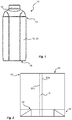
- the package 10 being manufactured in accordance with the method described above in the background section, comprises a main body 12 formed by a sleeve 20 of packaging material, and a plastic top 14 closing the upper end 16 of the main body 12.
- the sleeve 20 is shown also in Fig. 2 , before the plastic top 14 is moulded onto it.
- the sleeve 20 is formed by a sheet of packaging material being folded such that the longitudinal edges 22a, 22b overlap. In this position the sleeve 20 is sealed, such that the longitudinal edges 22a, 22b are joined.
- the packaging material typically has polymeric layers arranged both as its innermost and outmost layers, such lamination is possible by applying heat and pressure.
- the sealed overlap is commonly known as the longitudinal sealing LS.
- Fig. 2 the upper end 16' is indicated, which will form the upper end 16 of the main body during manufacturing. Also the bottom end 18' is indicated.
- the bottom end 18' of the sleeve 20 is provided with a number of crease lines 24 in order to facilitate folding and forming of the closed bottom end 18 of the package 10 indicated in Fig. 1 .
- this bottom end 18 of the package 10 is planar such that the package 10 may stand properly.
- the sleeve 20 is erected to a somewhat cylindrical body, and then arranged onto a mandrel for moulding of the plastic top 14 immediately onto the upper end 16' of the sleeve 20.
- measurements of the sleeve size is desired. This is preferably done off-line, i.e. external to the production equipment. For example, when a new batch of pre-manufactured sleeves 20 arrive at the production facility some samples may be measured, thus indicating the proper dimensions of the entire batch.
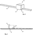
- the cutting device 30 comprises a ruler 32 being dimensioned to extend along at least a part of the longitudinal direction of the sleeve 20.
- the ruler 32 is provided with a knife holder 34 being securely attached to it, whereby the knife holder 34 accommodates a knife 36 protruding out from the knife holder 34 to some extent.
- the knife 36 is aligned with the extension of the ruler 32, but arranged at a transversal distance from the ruler 32.
- the cutting device 30 is positioned onto a sleeve 20 having its longitudinal sealing LS facing upwards.
- the cutting device 30 is aligned such that the ruler 32 is in contact with the edge of the longitudinal sealing LS, i.e. the step formed by the upper layer of packaging material overlapping the lower layer of packaging material.
- the cutting device 30 is moved in the longitudinal direction thereby cutting the sleeve 20.
- the knife holder 34 is slidably attached to the ruler 32 such that during cutting the ruler 32 remains stationary while the knife holder 34, and its associated knife 36, moves along the sleeve 20. Once cut, the sleeve 20 is ready for size metering.
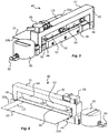
- a sleeve size metering device 40 is shown in Figs. 5 and 6 .
- the sleeve size metering device 40 comprises a frame 42.
- the frame 42 comprises a bottom surface 44 used for receiving the cut sleeve 20, and a distal surface 46 forming a stop for the sleeve 20.
- the distal surface 46 is configured to receive a longitudinal edge 22a of the sleeve 20 as is clearly shown in Fig. 6 .
- the distal surface 46 is preferably formed by a part of the frame 42 extending vertically upwards from the bottom surface 44.
- the frame 42 is also provided with a lateral surface 48, formed by a stop member 50 and facing the sleeve 20.
- the lateral surface 48 is perpendicular to the distal surface 46, and thereby configured to receive the upper or bottom edge of the sleeve 20.
- the frame 42 also comprises an upper bar 51, extending in parallel with the bottom surface 44 at a vertical distance thereof.
- the upper bar 51 is provided with two gas cylinders 52, 54 being connected to a common pressure member 56.
- Each gas cylinder 52, 54 is connected to a supply 58 of pressurized air.
- the pressure member 56 is moveable in the vertical direction by activation of the gas cylinders 52, 54. By such activation the pressure member 56 comes into contact with the sleeve 20, thereby planarizing the sleeve 20 as well as any irregularities present, such as crease lines.
- the sleeve size metering device 40 is further provided with a measurement unit 60, here in the form of a dial indicator.
- the dial indicator 60 is provided with a probe 62 (see Fig. 7 ), having a specific idle position.
- the dial indicator 60 is arranged at the end of the bottom surface 44, opposite the distal surface 46.
- the horizontal distance HD (see Fig. 7 ) between the distal surface 46 and the probe 62, when in the idle position, is well-defined and predetermined. Hence, this horizontal distance forms a reference distance used to determine the width of the sleeve 20, i.e. the circumference of the main body 12 of the package 10.
- the probe 62 is maneuvered by means of a handle 64.
- the handle 64 is accessed to move the probe 62 in contact with the longitudinal edge 22b of the sleeve 20.
- the movement of the probe 62 is measured accurately by the dial indicator. Hence the width of the sleeve 20 will be measured from the well-defined reference distance HD, adjusted by the horizontal movement of the probe 62.
- the probe 62 is returned to its idle position and the sleeve 20 is removed after deactivating the gas cylinders 52, 54 thus also releasing the pressure from the pressure member 56.
- the sleeve size metering device 40 is then again ready for a new measurement on another sleeve sample.
- Fig. 7 Further details of the sleeve size metering device 40 are shown in Fig. 7 . As can be seen in Fig. 7 pressurized air enters the supply 58, and is fed through drilled conduits within the frame 42 to each gas cylinder 52, 54. These gas cylinders 52, 54 are rigidly attached to the pressure member 56 providing an equal pressure to the entire sleeve 20.
- the flattening means should operate in a manner ensuring that any crease lines present on the sleeve 20 will be flattened. Also, the flattening means should provide a fix position of the sleeve 20 during measurements.
- the dial indicator 60 could also be replaced by any other device being suitable for measuring a distance between a reference surface 44 and a measuring point, in which measuring point there is a contact to the longitudinal edge 22b of the sleeve 20.
- a method 100 is schematically illustrated.
- the method 100 is performed in order to accurately measure the actual circumference of the sleeve 20, as described above.
- the method comprises a first step 102 of cutting the sleeve 20 in a longitudinal direction, preferably in a direction being parallel to, but spaced apart from, a longitudinal sealing LS of the sleeve 20.
- a second step 104 one longitudinal edge 22a of the sleeve 20 is positioned against a distal surface 46.
- This step may further comprise aligning one edge of the sleeve 20 with a lateral surface 48 arranged perpendicular to the distal surface 46.
- a step 105 of fixating the sleeve 20 is performed before a step 106 of positioning the probe.
- the probe 62 of a measurement unit 60 is positioned in contact with the opposite longitudinal edge 22b of the sleeve 20.
- a last step 108 the distance between the distal surface 46 and the probe 62, corresponding to the circumference of the sleeve 20 prior to cutting 102, is determined as explained earlier.
Landscapes
- Physics & Mathematics (AREA)
- General Physics & Mathematics (AREA)
- Making Paper Articles (AREA)
Abstract
A method for measuring the size of a sleeve (20) of a packaging material is provided. The method comprises cutting (102) the sleeve (20) in a longitudinal direction, positioning (104) one longitudinal edge (22a) of the sleeve (20) against a distal surface (46), positioning (106) a probe (62) of a measurement unit (60) in contact with the opposite longitudinal edge (22b) of the sleeve (20), and determining (108) the distance between the distal surface (46) and the probe (62) corresponding to the circumference of the sleeve (20) prior to cutting (102).
Description
- The invention relates to a sleeve size metering device, as well as to a method for measuring the actual size of a sleeve made of a packaging material and intended to form a body of a liquid food package.
- Packages, in particular individual liquid food packages, are typically manufactured at a very high speed. Although production and filling of such packages may be performed in various ways, one principle gaining increased market recognition during the recent years includes forming a cylindrical open ended body of a carton-based packaging material, and providing this sleeve-like body with a closed plastic top. When the plastic top is in place the now semi-finished package is filled through its still open bottom end, whereafter the bottom portion of the sleeve-like body is folded and sealed to form a substantially planar closed end.
- When manufacturing packages according to this general principles the sleeve-like body of carton-based packaging material is provided as a blank, being sealed along its longitudinal edges by means of a certain overlap and folded along longitudinal crease lines. The term longitudinal should be understood as perpendicular to the transport direction of the blank through the machine before the seal is formed.
- The sleeve-like body is thus fed to the filling machine as a flattened piece of packaging material. Once entering the filling machine the sleeve-like body of packaging material is erected and arranged onto a mandrel, which then is moved adjacent to and facing a mould. The mould and the mandrel together define a cavity into which molten plastic material is injected during injection moulding of the plastic top. The plastic top is thereby formed immediately onto the upper end of the erected sleeve.
- As is understood, it is important to have a good fit between the erected sleeve and the mandrel. Should the sleeve be too small increased forces are required to fit the sleeve onto the mandrel, thereby increasing the risk of damaging the packaging material and obtaining a less than optimal centering of the plastic on top of the sleeve.. In a similar manner there is an increased risk of damaging the packaging material if the sleeve is too big; the mould will in such case not accommodate the sleeve properly and possibly result in gaps beteen the sleeve and the plastic top.
- Several techniques for measuring the circumference of a sleeve have been suggested in order to ensure a proper fit of the sleeve with regards to the mandrel and the mould used for injection moulding the plastic top onto the sleeve. One device is a metal cone, having circumference indicating lines engraved along its periphery at different radii. The sleeve is arranged onto the cone and pressurized air is used for pressing the sleeve onto the cone; the final position of the sleeve will then be converted to a corresponding size by reading the engraved lines.
- The prior art allows for off-line metering of the sleeve size. However, some drawbacks are associated with this technique. For example, different packaging material will experience different friction against the metal cone. The applied air pressure must therefore be adjusted based on friction, which is an extremely difficult task. Another drawback is associated with the fact that the engraved metering lines are arranged at discrete positions. No explicit value can thus be extracted from this metering technique, but only an estimated value based on the values corresponding to the most adjacent lines.
- It is an object of the invention to at least partly overcome one or more of the above-identified limitations of the prior art. In particular, it is an object to provide a sleeve size metering device which is capable of providing an explicit value of the circumference of the sleeve independently of material properties of the packaging material.
- To solve these objects a method for measuring the size of a sleeve is provided. The method comprises a first step of cutting the sleeve in a longitudinal direction, a second step of positioning one longitudinal edge of the sleeve against a distal surface, and a third step of positioning a probe of a measurement unit in contact with the opposite longitudinal edge of the sleeve. From here, the method continues with a fourth step of determining the distance between the distal surface and the probe corresponding to the circumference of the sleeve prior to cutting.
- According to an embodiment cutting is performed in a direction being parallel to, but spaced apart from, a longitudinal sealing of the sleeve. This ensures that the cut, which provides a surface to contact the distal surface during measurement, is in fact a surface being perpendicular to the longitudinal extension of the sleeve.
- The method may further comprise fixating the sleeve before positioning said probe. This is advantageous in that any irregularities, such as crease lines, present on the packaging material of the sleeve will be flattened whereby its possible impact on the size measurement will be minimized.
- Fixating the sleeve may be performed by activating at least one gas cylinder, which is advantageous in that an equal pressure may be distributed across the entire width of the sleeve.
- The step of positioning the sleeve may further comprise aligning one edge of the sleeve with a lateral surface arranged perpendicular to the distal surface. By such alignment it is ensured that the measured width is perpendicular to the longitudinal extension of the sleeve.
- According to a second aspect a sleeve size metering device is provided. The sleeve size metering device comprises a distal surface configured to receive a longitudinal edge of the sleeve, and a measurement unit. The measurement unit has a probe which is moveable from an idle position to a measurement position, wherein the measurement unit is configured to determine the circumference of the sleeve by determining the distance between the distal surface and the probe when in the measurement position, from a predetermined distance between the distal surface and the probe when in the idle position.
- The measurement unit may be a dial indicator. In such embodiment metering is made possible using readily available equipment.
- The sleeve size metering device may further comprise means for flattening the sleeve; for example, the flattening means comprises one or more gas cylinder being connected to at least one pressure member. This is advantageous in that any irregularities, such as crease lines, present on the packaging material of the sleeve will be flattened whereby its possible impact on the size measurement will be minimized.
- The sleeve size metering device may further comprise a lateral surface, preferably being perpendicular to the distal surface, for receiving an edge of the sleeve during operation. By such alignment it is ensured that the measured width is perpendicular to the longitudinal extension of the sleeve.
- Still other objectives, features, aspects and advantages of the invention will appear from the following detailed description as well as from the drawings.
- Embodiments of the invention will now be described, by way of example, with reference to the accompanying schematic drawings, in which
-
Fig. 1 is a front view of a package comprising a plastic top and a main body formed from a sleeve of a carton-based packaging material; -
Fig. 2 is a top view of flattened sleeve of packaging material intended to form a main body of a package; -
Fig. 3 is a perspective view of a cutting device; -
Fig. 4 is a side view of the cutting device shown inFig. 3 positioned to cut a sleeve of packaging material; -
Fig. 5 is a perspective view of a sleeve size metering device according to an embodiment, here showing the rear of the device; -
Fig. 6 is a perspective view of the sleeve size metering device shown inFig. 5 , here showing the front of the device; -
Fig. 7 is a cross-sectional view of the sleeve size metering device shown inFigs. 5 and 6 ; and -
Fig. 8 is a schematic view of a sleeve size metering method according to an embodiment. - With reference to
Fig. 1 apackage 10 is illustrated. Thepackage 10, being manufactured in accordance with the method described above in the background section, comprises a main body 12 formed by asleeve 20 of packaging material, and aplastic top 14 closing theupper end 16 of the main body 12. - The
sleeve 20 is shown also inFig. 2 , before theplastic top 14 is moulded onto it. Thesleeve 20 is formed by a sheet of packaging material being folded such that thelongitudinal edges sleeve 20 is sealed, such that thelongitudinal edges - In
Fig. 2 the upper end 16' is indicated, which will form theupper end 16 of the main body during manufacturing. Also the bottom end 18' is indicated. The bottom end 18' of thesleeve 20 is provided with a number ofcrease lines 24 in order to facilitate folding and forming of the closedbottom end 18 of thepackage 10 indicated inFig. 1 . Preferably thisbottom end 18 of thepackage 10 is planar such that thepackage 10 may stand properly. - As explained above when the
package 10 is to be formed thesleeve 20 is erected to a somewhat cylindrical body, and then arranged onto a mandrel for moulding of the plastic top 14 immediately onto the upper end 16' of thesleeve 20. - For ensuring the correct moulding operation, and hence also the desired integrity and quality of the resulting
package 10, measurements of the sleeve size is desired. This is preferably done off-line, i.e. external to the production equipment. For example, when a new batch ofpre-manufactured sleeves 20 arrive at the production facility some samples may be measured, thus indicating the proper dimensions of the entire batch. - In order to measure the sleeve size in accordance with the invention described within this specification, it is required to cut the
sleeve 20 in the longitudinal direction. A cuttingdevice 30 being developed for this sole purpose is shown inFig. 3 . The cuttingdevice 30 comprises aruler 32 being dimensioned to extend along at least a part of the longitudinal direction of thesleeve 20. Theruler 32 is provided with aknife holder 34 being securely attached to it, whereby theknife holder 34 accommodates aknife 36 protruding out from theknife holder 34 to some extent. Theknife 36 is aligned with the extension of theruler 32, but arranged at a transversal distance from theruler 32. - During operation the cutting
device 30 is positioned onto asleeve 20 having its longitudinal sealing LS facing upwards. The cuttingdevice 30 is aligned such that theruler 32 is in contact with the edge of the longitudinal sealing LS, i.e. the step formed by the upper layer of packaging material overlapping the lower layer of packaging material. Starting at one longitudinal end of thesleeve 20, the cuttingdevice 30 is moved in the longitudinal direction thereby cutting thesleeve 20. Optionally, theknife holder 34 is slidably attached to theruler 32 such that during cutting theruler 32 remains stationary while theknife holder 34, and its associatedknife 36, moves along thesleeve 20. Once cut, thesleeve 20 is ready for size metering. - A sleeve
size metering device 40 is shown inFigs. 5 and 6 . The sleevesize metering device 40 comprises aframe 42. Theframe 42 comprises abottom surface 44 used for receiving thecut sleeve 20, and adistal surface 46 forming a stop for thesleeve 20. Thedistal surface 46 is configured to receive alongitudinal edge 22a of thesleeve 20 as is clearly shown inFig. 6 . Thedistal surface 46 is preferably formed by a part of theframe 42 extending vertically upwards from thebottom surface 44. Theframe 42 is also provided with alateral surface 48, formed by astop member 50 and facing thesleeve 20. Thelateral surface 48 is perpendicular to thedistal surface 46, and thereby configured to receive the upper or bottom edge of thesleeve 20. - The
frame 42 also comprises anupper bar 51, extending in parallel with thebottom surface 44 at a vertical distance thereof. Theupper bar 51 is provided with twogas cylinders common pressure member 56. Eachgas cylinder supply 58 of pressurized air. Thepressure member 56 is moveable in the vertical direction by activation of thegas cylinders pressure member 56 comes into contact with thesleeve 20, thereby planarizing thesleeve 20 as well as any irregularities present, such as crease lines. - The sleeve
size metering device 40 is further provided with ameasurement unit 60, here in the form of a dial indicator. Thedial indicator 60 is provided with a probe 62 (seeFig. 7 ), having a specific idle position. Thedial indicator 60 is arranged at the end of thebottom surface 44, opposite thedistal surface 46. - The horizontal distance HD (see
Fig. 7 ) between thedistal surface 46 and theprobe 62, when in the idle position, is well-defined and predetermined. Hence, this horizontal distance forms a reference distance used to determine the width of thesleeve 20, i.e. the circumference of the main body 12 of thepackage 10. - The
probe 62 is maneuvered by means of ahandle 64. When the unfoldedsleeve 20 is positioned correctly and locked in position by activation of thegas cylinders handle 64 is accessed to move theprobe 62 in contact with thelongitudinal edge 22b of thesleeve 20. The movement of theprobe 62 is measured accurately by the dial indicator. Hence the width of thesleeve 20 will be measured from the well-defined reference distance HD, adjusted by the horizontal movement of theprobe 62. - Once measurement is done the
probe 62 is returned to its idle position and thesleeve 20 is removed after deactivating thegas cylinders pressure member 56. The sleevesize metering device 40 is then again ready for a new measurement on another sleeve sample. - Further details of the sleeve
size metering device 40 are shown inFig. 7 . As can be seen inFig. 7 pressurized air enters thesupply 58, and is fed through drilled conduits within theframe 42 to eachgas cylinder gas cylinders pressure member 56 providing an equal pressure to theentire sleeve 20. - As is evident, other means for flattening the
sleeve 20 may be provided instead of thegas cylinders pressure member 56. For example, thee components could be replaced by a vacuum pump drawing thesleeve 20 towards thebottom surface 44. Preferably the flattening means should operate in a manner ensuring that any crease lines present on thesleeve 20 will be flattened. Also, the flattening means should provide a fix position of thesleeve 20 during measurements. - The
dial indicator 60 could also be replaced by any other device being suitable for measuring a distance between areference surface 44 and a measuring point, in which measuring point there is a contact to thelongitudinal edge 22b of thesleeve 20. - As can be seen in
Fig. 7 the reference distance HD is a constant value between thedistal surface 46 and the end of theprobe 62. When measuring the sleeve size theprobe 62 is retracted, or moved to the right inFig. 7 , thus allowing asleeve 20 to fit between thedistal surface 46 and the end of theprobe 62. Once thesleeve 20 is correctly positioned against thedistal surface 46 and thelateral surface 48, theprobe 62 is allowed to return back towards its idle position. However before theprobe 62 reaches its idle positon theprobe 62 will contact thelongitudinal edge 22b of the sleeve. The dial indicator will measure the distance between the idle position and the current position of theprobe 62, in which current position theprobe 62 rests against thelongitudinal edge 22b of thesleeve 20. - Now turning to
Fig. 8 amethod 100 is schematically illustrated. Themethod 100 is performed in order to accurately measure the actual circumference of thesleeve 20, as described above. The method comprises afirst step 102 of cutting thesleeve 20 in a longitudinal direction, preferably in a direction being parallel to, but spaced apart from, a longitudinal sealing LS of thesleeve 20. In asecond step 104 onelongitudinal edge 22a of thesleeve 20 is positioned against adistal surface 46. This step may further comprise aligning one edge of thesleeve 20 with alateral surface 48 arranged perpendicular to thedistal surface 46. - Optionally, a
step 105 of fixating thesleeve 20 is performed before astep 106 of positioning the probe. Instep 106, theprobe 62 of ameasurement unit 60 is positioned in contact with the oppositelongitudinal edge 22b of thesleeve 20. - In a
last step 108 the distance between thedistal surface 46 and theprobe 62, corresponding to the circumference of thesleeve 20 prior to cutting 102, is determined as explained earlier. - From the description above follows that, although various embodiments of the invention have been described and shown, the invention is not restricted thereto, but may also be embodied in other ways within the scope of the subject-matter defined in the following claims.
Claims (12)
- A method for measuring the size of a sleeve (20) of a packaging material, the method comprising:cutting (102) the sleeve (20) in a longitudinal direction,positioning (104) one longitudinal edge (22a) of the sleeve (20) against a distal surface (46),positioning (106) a probe (62) of a measurement unit (60) in contact with the opposite longitudinal edge (22b) of the sleeve (20), anddetermining (108) the distance between the distal surface (46) and the probe (62) corresponding to the circumference of the sleeve (20) prior to cutting (102).
- The method according to claim 1, wherein cutting (102) is performed in a direction being parallel to, but spaced apart from, a longitudinal sealing (LS) of the sleeve (20).
- The method according to claim 1 or 2, further comprising fixating (105) the sleeve (20) before positioning (106) said probe (62).
- The method according to claim 3, wherein fixating (105) is performed by activating at least one gas cylinder (52, 54).
- The method according to any one of the preceding claims, wherein positioning (104) the sleeve (20) further comprises aligning one edge of the sleeve (20) with a lateral surface (48) arranged perpendicular to the distal surface (46).
- A sleeve size metering device (40), comprising a distal surface (46) and a measurement unit (60), said measurement unit (60) having a probe (62) which is moveable from an idle position to a measurement position, wherein the measurement unit (60) is configured to determine the circumference of a sleeve (20) by determining the distance between the distal surface (46) and the probe (62) when in the measurement position, from a predetermined distance (HD) between the distal surface (46) and the probe (62) when in the idle position.
- The sleeve size metering device (40) according to claim 6, wherein the measurement unit (60) is a dial indicator.
- The sleeve size metering device (40) according to claim 6 or 7, further comprising means for flattening the sleeve (20).
- The sleeve size metering device (40) according to claim 8, wherein said flattening means comprises at least one gas cylinder (52, 54) being connected to a pressure member (56).
- The sleeve size metering device (40) according to claim 9, wherein a plurality of gas cylinders (52, 54) are connected to a common pressure member (56).
- The sleeve size metering device (40) according to any one of claims 6-9, further comprising a lateral surface (58) for receiving an edge of the sleeve (20) during operation.
- The sleeve size metering device (40) according to claim 11, wherein the lateral surface (48) is perpendicular to the distal surface (46).
Priority Applications (1)
| Application Number | Priority Date | Filing Date | Title |
|---|---|---|---|
| EP17206455.2A EP3495764A1 (en) | 2017-12-11 | 2017-12-11 | A sleeve size metering device, and a method |
Applications Claiming Priority (1)
| Application Number | Priority Date | Filing Date | Title |
|---|---|---|---|
| EP17206455.2A EP3495764A1 (en) | 2017-12-11 | 2017-12-11 | A sleeve size metering device, and a method |
Publications (1)
| Publication Number | Publication Date |
|---|---|
| EP3495764A1 true EP3495764A1 (en) | 2019-06-12 |
Family
ID=60661826
Family Applications (1)
| Application Number | Title | Priority Date | Filing Date |
|---|---|---|---|
| EP17206455.2A Withdrawn EP3495764A1 (en) | 2017-12-11 | 2017-12-11 | A sleeve size metering device, and a method |
Country Status (1)
| Country | Link |
|---|---|
| EP (1) | EP3495764A1 (en) |
Citations (3)
| Publication number | Priority date | Publication date | Assignee | Title |
|---|---|---|---|---|
| US3235968A (en) * | 1963-05-20 | 1966-02-22 | Stanley A Wertepny | Length gauge |
| US3772796A (en) * | 1971-02-12 | 1973-11-20 | Nat Steel Corp | Apparatus for linear measurement of sheets |
| WO2010146375A2 (en) * | 2009-06-18 | 2010-12-23 | Elopak Systems Ag | Apparatus and method |
-
2017
- 2017-12-11 EP EP17206455.2A patent/EP3495764A1/en not_active Withdrawn
Patent Citations (3)
| Publication number | Priority date | Publication date | Assignee | Title |
|---|---|---|---|---|
| US3235968A (en) * | 1963-05-20 | 1966-02-22 | Stanley A Wertepny | Length gauge |
| US3772796A (en) * | 1971-02-12 | 1973-11-20 | Nat Steel Corp | Apparatus for linear measurement of sheets |
| WO2010146375A2 (en) * | 2009-06-18 | 2010-12-23 | Elopak Systems Ag | Apparatus and method |
Similar Documents
| Publication | Publication Date | Title |
|---|---|---|
| RU2018101298A (en) | DEVICE AND METHOD OF MANUFACTURING PLASTIC PACKAGES | |
| CN105881101B (en) | The detection device and its control method of wheel hub | |
| CN107764188A (en) | A kind of silicon single crystal rod length and gradient detection means and its detection method | |
| CN106660254B (en) | Determination of impact travel by drawing in container manufacturing equipment | |
| CN113670165A (en) | Flexible circuit board detection device | |
| CN110733148A (en) | A kind of installation method of wind turbine blade web mold bonding rib | |
| CN208505180U (en) | A kind of measuring thickness device | |
| ITUA20164663A1 (en) | METHOD AND PANEL CUTTING MACHINE | |
| CN209689543U (en) | A kind of side wall oil filler auxiliary detection instrument | |
| CN112484613A (en) | Coaxiality and symmetry detection method | |
| CN104713459B (en) | A kind of double ball mensurations of counterbore angle | |
| CN205628479U (en) | Adhesive deposite device and point gum machine | |
| US5148611A (en) | Multimeasurement gauge assembly | |
| JPS5818223A (en) | Molding method | |
| CN206959733U (en) | A kind of detection means of bevel at small end of connecting rod | |
| CN107834789B (en) | Automatic lamination equipment of rotor | |
| CN214308489U (en) | Cavity glass stacking error detection device | |
| CN112240732B (en) | Injection mold form and position tolerance measurement gauge | |
| CN208766113U (en) | A kind of localization tool of medicine bottle infrared detection | |
| US3090418A (en) | Locating tool for sheet metal bending and process for locating a metal sheet for bending | |
| CN110160846B (en) | End reinforcement method and device for 3D printing P L A silk strength test | |
| JPH02195231A (en) | Adhesive-strength measuring apparatus | |
| CN206311374U (en) | For the sample soil sampler of cohesive soil combined measurement method of liquid and plastic limits experiment | |
| CN207456349U (en) | A kind of die hole hole diameter detection apparatus | |
| CN202757864U (en) | Copper mould used for testing road surface crack-pouring adhesive flow value |
Legal Events
| Date | Code | Title | Description |
|---|---|---|---|
| PUAI | Public reference made under article 153(3) epc to a published international application that has entered the european phase |
Free format text: ORIGINAL CODE: 0009012 |
|
| STAA | Information on the status of an ep patent application or granted ep patent |
Free format text: STATUS: THE APPLICATION HAS BEEN PUBLISHED |
|
| AK | Designated contracting states |
Kind code of ref document: A1 Designated state(s): AL AT BE BG CH CY CZ DE DK EE ES FI FR GB GR HR HU IE IS IT LI LT LU LV MC MK MT NL NO PL PT RO RS SE SI SK SM TR |
|
| AX | Request for extension of the european patent |
Extension state: BA ME |
|
| STAA | Information on the status of an ep patent application or granted ep patent |
Free format text: STATUS: THE APPLICATION IS DEEMED TO BE WITHDRAWN |
|
| 18D | Application deemed to be withdrawn |
Effective date: 20191213 |