EP3495759A1 - Heat exchanger with spray nozzle - Google Patents
Heat exchanger with spray nozzle Download PDFInfo
- Publication number
- EP3495759A1 EP3495759A1 EP18211631.9A EP18211631A EP3495759A1 EP 3495759 A1 EP3495759 A1 EP 3495759A1 EP 18211631 A EP18211631 A EP 18211631A EP 3495759 A1 EP3495759 A1 EP 3495759A1
- Authority
- EP
- European Patent Office
- Prior art keywords
- heat exchanger
- nozzle
- nozzles
- pipe
- cold side
- Prior art date
- Legal status (The legal status is an assumption and is not a legal conclusion. Google has not performed a legal analysis and makes no representation as to the accuracy of the status listed.)
- Granted
Links
Images


Classifications
-
- F—MECHANICAL ENGINEERING; LIGHTING; HEATING; WEAPONS; BLASTING
- F28—HEAT EXCHANGE IN GENERAL
- F28D—HEAT-EXCHANGE APPARATUS, NOT PROVIDED FOR IN ANOTHER SUBCLASS, IN WHICH THE HEAT-EXCHANGE MEDIA DO NOT COME INTO DIRECT CONTACT
- F28D5/00—Heat-exchange apparatus having stationary conduit assemblies for one heat-exchange medium only, the media being in contact with different sides of the conduit wall, using the cooling effect of natural or forced evaporation
-
- F—MECHANICAL ENGINEERING; LIGHTING; HEATING; WEAPONS; BLASTING
- F28—HEAT EXCHANGE IN GENERAL
- F28F—DETAILS OF HEAT-EXCHANGE AND HEAT-TRANSFER APPARATUS, OF GENERAL APPLICATION
- F28F9/00—Casings; Header boxes; Auxiliary supports for elements; Auxiliary members within casings
- F28F9/02—Header boxes; End plates
- F28F9/026—Header boxes; End plates with static flow control means, e.g. with means for uniformly distributing heat exchange media into conduits
- F28F9/0282—Header boxes; End plates with static flow control means, e.g. with means for uniformly distributing heat exchange media into conduits by varying the geometry of conduit ends, e.g. by using inserts or attachments for modifying the pattern of flow at the conduit inlet or outlet
-
- F—MECHANICAL ENGINEERING; LIGHTING; HEATING; WEAPONS; BLASTING
- F28—HEAT EXCHANGE IN GENERAL
- F28D—HEAT-EXCHANGE APPARATUS, NOT PROVIDED FOR IN ANOTHER SUBCLASS, IN WHICH THE HEAT-EXCHANGE MEDIA DO NOT COME INTO DIRECT CONTACT
- F28D7/00—Heat-exchange apparatus having stationary tubular conduit assemblies for both heat-exchange media, the media being in contact with different sides of a conduit wall
- F28D7/0066—Multi-circuit heat-exchangers, e.g. integrating different heat exchange sections in the same unit or heat-exchangers for more than two fluids
-
- F—MECHANICAL ENGINEERING; LIGHTING; HEATING; WEAPONS; BLASTING
- F28—HEAT EXCHANGE IN GENERAL
- F28F—DETAILS OF HEAT-EXCHANGE AND HEAT-TRANSFER APPARATUS, OF GENERAL APPLICATION
- F28F9/00—Casings; Header boxes; Auxiliary supports for elements; Auxiliary members within casings
- F28F9/02—Header boxes; End plates
- F28F9/026—Header boxes; End plates with static flow control means, e.g. with means for uniformly distributing heat exchange media into conduits
- F28F9/0263—Header boxes; End plates with static flow control means, e.g. with means for uniformly distributing heat exchange media into conduits by varying the geometry or cross-section of header box
-
- B—PERFORMING OPERATIONS; TRANSPORTING
- B33—ADDITIVE MANUFACTURING TECHNOLOGY
- B33Y—ADDITIVE MANUFACTURING, i.e. MANUFACTURING OF THREE-DIMENSIONAL [3D] OBJECTS BY ADDITIVE DEPOSITION, ADDITIVE AGGLOMERATION OR ADDITIVE LAYERING, e.g. BY 3D PRINTING, STEREOLITHOGRAPHY OR SELECTIVE LASER SINTERING
- B33Y80/00—Products made by additive manufacturing
-
- B—PERFORMING OPERATIONS; TRANSPORTING
- B64—AIRCRAFT; AVIATION; COSMONAUTICS
- B64D—EQUIPMENT FOR FITTING IN OR TO AIRCRAFT; FLIGHT SUITS; PARACHUTES; ARRANGEMENT OR MOUNTING OF POWER PLANTS OR PROPULSION TRANSMISSIONS IN AIRCRAFT
- B64D13/00—Arrangements or adaptations of air-treatment apparatus for aircraft crew or passengers, or freight space
- B64D13/06—Arrangements or adaptations of air-treatment apparatus for aircraft crew or passengers, or freight space the air being conditioned
- B64D2013/0603—Environmental Control Systems
-
- B—PERFORMING OPERATIONS; TRANSPORTING
- B64—AIRCRAFT; AVIATION; COSMONAUTICS
- B64D—EQUIPMENT FOR FITTING IN OR TO AIRCRAFT; FLIGHT SUITS; PARACHUTES; ARRANGEMENT OR MOUNTING OF POWER PLANTS OR PROPULSION TRANSMISSIONS IN AIRCRAFT
- B64D13/00—Arrangements or adaptations of air-treatment apparatus for aircraft crew or passengers, or freight space
- B64D13/06—Arrangements or adaptations of air-treatment apparatus for aircraft crew or passengers, or freight space the air being conditioned
- B64D2013/0603—Environmental Control Systems
- B64D2013/0618—Environmental Control Systems with arrangements for reducing or managing bleed air, using another air source, e.g. ram air
-
- F—MECHANICAL ENGINEERING; LIGHTING; HEATING; WEAPONS; BLASTING
- F28—HEAT EXCHANGE IN GENERAL
- F28F—DETAILS OF HEAT-EXCHANGE AND HEAT-TRANSFER APPARATUS, OF GENERAL APPLICATION
- F28F9/00—Casings; Header boxes; Auxiliary supports for elements; Auxiliary members within casings
- F28F9/02—Header boxes; End plates
- F28F2009/0285—Other particular headers or end plates
- F28F2009/0292—Other particular headers or end plates with fins
-
- Y—GENERAL TAGGING OF NEW TECHNOLOGICAL DEVELOPMENTS; GENERAL TAGGING OF CROSS-SECTIONAL TECHNOLOGIES SPANNING OVER SEVERAL SECTIONS OF THE IPC; TECHNICAL SUBJECTS COVERED BY FORMER USPC CROSS-REFERENCE ART COLLECTIONS [XRACs] AND DIGESTS
- Y02—TECHNOLOGIES OR APPLICATIONS FOR MITIGATION OR ADAPTATION AGAINST CLIMATE CHANGE
- Y02T—CLIMATE CHANGE MITIGATION TECHNOLOGIES RELATED TO TRANSPORTATION
- Y02T50/00—Aeronautics or air transport
- Y02T50/50—On board measures aiming to increase energy efficiency
Definitions
- ECS Environmental Control Systems
- ECS provide air supply, thermal control, and cabin pressurization for an aircraft.
- ECS can also provide avionics cooling, smoke detection, fire suppression, or other functions.
- ECS systems typically receive bleed air from an aircraft engine, and cool the bleed air with an air-conditioning "pack." The pack is cooled by ram (outside) air from a ram air duct.
- ambient air can have high humidity.
- the bleed air is dehumidified. Free water collects in a system water extractor in the ECS. The water is then directed to one more spray nozzles arranged in the ram air duct, typically on a cold side of the ram air duct inlet header. The spray nozzles spray water droplets into the ram air stream, and the water droplets evaporate. The evaporation process provides additional cooling for air that is ultimately sent to the aircraft cabin.
- An environmental control system includes a heat exchanger, a ram air duct operable to provide cooling ram air to the heat exchanger, and a water extractor operable to extract water from the ram air.
- the heat exchanger includes at least one nozzle operable to spray water from the water extractor into the ram air duct.
- At least one nozzle is arranged along a pipe in fluid communication with the water extractor.
- the pipe is located along a cold side of the heat exchanger, the cold side of the heat exchanger facing the ram air duct.
- the pipe is inside the heat exchanger.
- At least one nozzle extends from the pipe through the cold side of the heat exchanger.
- At least one nozzle includes an orifice for spraying the water, and the orifice is exterior to the heat exchanger.
- At least one nozzle comprises a plurality of nozzles, and the plurality of nozzles are equidistant from one another.
- At least one nozzle comprises a plurality of nozzles, and the plurality of nozzles are equidistant from a top edge of the cold side of the heat exchanger.
- At least one nozzle comprises a plurality of nozzles, and the plurality of nozzles are arranged in a straight line.
- the heat exchanger is operable to provide conditioned air for an aircraft cabin.
- the heat exchanger is a plate-and-fin heat exchanger.
- the at least one nozzle is one of a fixed orifice nozzle and a pintle nozzle.
- a heat exchanger system includes a cold side, a pipe arranged along the cold side, and at least one nozzle.
- the at least one nozzle is arranged along the pipe and extends through the cold side.
- the pipe and the at least one nozzle are integral with the heat exchanger.
- At least one nozzle is operable to spray water to an exterior of the cold side.
- the at least one nozzle extends from the pipe through the cold side of the heat exchanger.
- At least one nozzle comprises a plurality of nozzles, and the plurality of nozzles are equidistant from one another.
- At least one nozzle comprises a plurality of nozzles, and the plurality of nozzles are equidistant from a top edge of the cold side.
- At least one nozzle comprises a plurality of nozzles, and the plurality of nozzles are arranged in a straight line.
- a method of making a heat exchanger includes forming a heat exchanger, and forming a pipe along a side of the heat exchanger and at least one nozzle along the pipe, and extending through the side of the heat exchanger.
- the pipe and the at least one nozzle are formed integrally with the heat exchanger as the heat exchanger is being formed.
- the forming is done by additive manufacturing.
- FIG. 1 schematically illustrates a prior art environmental control system (ECS) 10 for an aircraft.
- the ECS 10 provides conditioned air at a desired temperature and pressure to an aircraft cabin via a conditioned air outlet 11.
- the ECS includes a heat exchanger 12, which receives hot air and cools the hot air.
- the hot air can be bleed air from an aircraft engine (not shown), for example, bleed air from upstream of the aircraft engine compressor or from various stages of the aircraft engine compressor.
- the ECS 10 also includes a ram air duct 14, which intakes ram (outside or ambient) air.
- the ram air provides cooling to the heat exchanger 12.
- the ECS also includes a water extractor 16.
- the water extractor 16 dehumidifies (extracts water from) the bleed air, and collects the water.
- the water is then sent to the cold circuit of the heat exchanger 12 via one or more spray nozzles 18 in the ram air duct 14.
- the spray nozzle 18 is located in an inlet header 20 of the ram air duct 14.
- the spray nozzle 18 releases water droplets into the ram air duct 14, and the water droplets evaporate. This evaporation provides additional cooling to the heat exchanger 12.
- the spray nozzle 18 is a separate part that is bolted onto or otherwise attached to the ram inlet header 20.
- the ECS 100 provides conditioned air at a desired temperature and pressure to an aircraft cabin via a conditioned air outlet 110.
- the ECS 100 includes a heat exchanger 120, which receives hot air and cools the hot air.
- the hot air can be bleed air from an aircraft engine (not shown), for example, bleed air from upstream of the aircraft engine compressor or from various stages of the aircraft engine compressor.
- the heat exchanger 120 is a plate and fin heat exchanger, but other heat exchanger geometries and types are contemplated.
- the ECS 100 also includes a ram air duct 140, which intakes ram (outside or ambient) air.
- the ram air provides cooling to the heat exchanger 120.
- the heat exchanger 120 has a cold side 121, which faces the ram air duct 140.
- the ECS also includes a water extractor 160.
- the water extractor 160 dehumidifies (extracts water from) the bleed air, and collects the water. The water is then provided to one or more nozzles 180 in the heat exchanger 100, as is described in more detail below with reference to Figures 3-6 .
- FIGS 3-6 schematically show the heat exchanger 120.
- the heat exchanger 120 includes an integral pipe 165 which is in fluid communication with the water extractor 160 via a fitting 170.
- the pipe is arranged along the cold side 121 of the heat exchanger 120, within the volume of the heat exchanger 120.
- Nozzles 180 are arranged along the pipe 165 and extend from the pipe 165 (e.g., the interior of heat exchanger 120) through the cold side 121, with an orifice 190 exterior to the heat exchanger 120.
- Nozzles 180 spray water droplets to an exterior of the cold side 121 of the heat exchanger 120, into the ram air duct 140, where the droplets evaporate. This evaporation provides additional cooling to the heat exchanger 120.
- the nozzles 180 and pipe 165 are integral with the heat exchanger 110. That is, the heat exchanger 120, nozzles 180, and pipe 165 are a unitary structure.
- the heat exchanger 120 is manufactured such that the nozzles 180 and pipe 165 are manufactured integrally into the heat exchanger 120 as it is being formed.
- the heat exchanger 110 and integral nozzles 180 and pipe 165 are made by any known additive manufacturing method. Additively manufacturing the heat exchanger 120 in this manner allows for placement of nozzles 180 and pipe 165 in any desired location of the heat exchanger 120, including locations which may otherwise be difficult to attached a nozzle 120. Accordingly, additively manufacturing the heat exchanger 120 increases design flexibility.
- nozzle 180 placement allows for more precise and thus more efficient nozzle 180 placement, for example, according to computational fluid dynamics (CFD) analysis, discussed below.
- CFD computational fluid dynamics
- This increases the overall efficiency of the ECS 100.
- nozzles 180 are integral with the heat exchanger 120, the need for separate mounting details and line-replaceable units (LRUs) is eliminated.
- the pipe 165 is straight such that the nozzles 180 are in a straight line parallel to the X axis.
- the nozzles 180 are located along X and Z axes of the heat exchanger 120. The location of the first nozzle corresponds to a displacement X 1 along the X axis and the displacement Z 1 along the Z axis, the location of the second corresponds to a displacement X 2 along the X axis and the displacement Z 2 along the Z axis, and so on.
- the location of the last nozzle corresponds to a displacement X n along the X axis and the displacement Z n along the Z axis, where n is the number of nozzles.
- the nozzles can be staggered with respect to one another, or located along a line angled with respect to one or both of the X and Z axes, or located in another arrangement.
- the X and Z displacements vary.
- the heat exchanger 120 has a length L along the X axis and a height H along the Z axis.
- the heat exchanger 120 has a length L of 90.9 cm (35.8 inches)
- each nozzle 180 is selected to maximize cooling efficiency of the heat exchanger 120. This in turn depends on the particular flow pattern of ram air passing by the cold side 121 of the heat exchanger 120.
- computational fluid dynamics (CFD) analysis is performed to determine the optimal nozzle 180 locations.
- the CFD analysis is performed when the ram air duct 140 is open, which occurs at ground conditions for the aircraft.
- Hot out hot outlet
- the number of nozzles 180 depends on the amount of and pressure of water in the water extractor 160 and fitting 170.
- the nozzles 180 can be any type of nozzle, such as a fixed orifice nozzle. Another type of nozzle is a pintle nozzle, which produces a more atomized water spray.
- the nozzles 180 have orifices 190 with diameters between about 1.524 and 3.048 mm (60 and 120 mils). Each nozzle 180 can have the same design and orifice diameter, or different design and orifice diameter.
Landscapes
- Engineering & Computer Science (AREA)
- Physics & Mathematics (AREA)
- Thermal Sciences (AREA)
- Mechanical Engineering (AREA)
- General Engineering & Computer Science (AREA)
- Geometry (AREA)
- Heat-Exchange Devices With Radiators And Conduit Assemblies (AREA)
- Devices For Blowing Cold Air, Devices For Blowing Warm Air, And Means For Preventing Water Condensation In Air Conditioning Units (AREA)
Abstract
Description
- Environmental Control Systems (ECS) provide air supply, thermal control, and cabin pressurization for an aircraft. ECS can also provide avionics cooling, smoke detection, fire suppression, or other functions. ECS systems typically receive bleed air from an aircraft engine, and cool the bleed air with an air-conditioning "pack." The pack is cooled by ram (outside) air from a ram air duct.
- However, ambient air can have high humidity. In order to avoid sending humid air to the aircraft cabin, the bleed air is dehumidified. Free water collects in a system water extractor in the ECS. The water is then directed to one more spray nozzles arranged in the ram air duct, typically on a cold side of the ram air duct inlet header. The spray nozzles spray water droplets into the ram air stream, and the water droplets evaporate. The evaporation process provides additional cooling for air that is ultimately sent to the aircraft cabin.
- An environmental control system according to an example of the present disclosure includes a heat exchanger, a ram air duct operable to provide cooling ram air to the heat exchanger, and a water extractor operable to extract water from the ram air. The heat exchanger includes at least one nozzle operable to spray water from the water extractor into the ram air duct.
- In a further embodiment according to the foregoing embodiment, at least one nozzle is arranged along a pipe in fluid communication with the water extractor.
- In a further embodiment according to any of the foregoing embodiments, the pipe is located along a cold side of the heat exchanger, the cold side of the heat exchanger facing the ram air duct.
- In a further embodiment according to any of the foregoing embodiments, the pipe is inside the heat exchanger.
- In a further embodiment according to any of the foregoing embodiments, at least one nozzle extends from the pipe through the cold side of the heat exchanger.
- In a further embodiment according to any of the foregoing embodiments, at least one nozzle includes an orifice for spraying the water, and the orifice is exterior to the heat exchanger.
- In a further embodiment according to any of the foregoing embodiments, at least one nozzle comprises a plurality of nozzles, and the plurality of nozzles are equidistant from one another.
- In a further embodiment according to any of the foregoing embodiments, at least one nozzle comprises a plurality of nozzles, and the plurality of nozzles are equidistant from a top edge of the cold side of the heat exchanger.
- In a further embodiment according to any of the foregoing embodiments, at least one nozzle comprises a plurality of nozzles, and the plurality of nozzles are arranged in a straight line.
- In a further embodiment according to any of the foregoing embodiments, the heat exchanger is operable to provide conditioned air for an aircraft cabin.
- In a further embodiment according to any of the foregoing embodiments, the heat exchanger is a plate-and-fin heat exchanger.
- In a further embodiment according to any of the foregoing embodiments, the at least one nozzle is one of a fixed orifice nozzle and a pintle nozzle.
- A heat exchanger system according to an example of the present disclosure includes a cold side, a pipe arranged along the cold side, and at least one nozzle. The at least one nozzle is arranged along the pipe and extends through the cold side. The pipe and the at least one nozzle are integral with the heat exchanger.
- In a further embodiment according to any of the foregoing embodiments, at least one nozzle is operable to spray water to an exterior of the cold side.
- In a further embodiment according to any of the foregoing embodiments, the at least one nozzle extends from the pipe through the cold side of the heat exchanger.
- In a further embodiment according to any of the foregoing embodiments, at least one nozzle comprises a plurality of nozzles, and the plurality of nozzles are equidistant from one another.
- In a further embodiment according to any of the foregoing embodiments, at least one nozzle comprises a plurality of nozzles, and the plurality of nozzles are equidistant from a top edge of the cold side.
- In a further embodiment according to any of the foregoing embodiments, at least one nozzle comprises a plurality of nozzles, and the plurality of nozzles are arranged in a straight line.
- A method of making a heat exchanger according to an example of the present disclosure includes forming a heat exchanger, and forming a pipe along a side of the heat exchanger and at least one nozzle along the pipe, and extending through the side of the heat exchanger. The pipe and the at least one nozzle are formed integrally with the heat exchanger as the heat exchanger is being formed.
- In a further embodiment according to any of the foregoing embodiments, the forming is done by additive manufacturing.
-
-
Figure 1 schematically illustrates a prior art environmental control system (ECS). -
Figure 2 schematically illustrates an environmental control system (ECS) according to the present disclosure. -
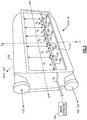
Figure 3 schematically illustrates an isometric view of a heat exchanger of the ECS ofFigure 2 . -
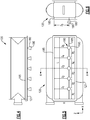
Figure 4 schematically illustrates a top-down orthogonal view of the heat exchanger ofFigure 3 . -
Figure 5 schematically illustrates side view of the heat exchanger ofFigures 3-4 . -
Figure 6 schematically illustrates a cutaway view of the heat exchanger ofFigures 3-5 along the section A-A (Figure 3 ). -
Figure 1 schematically illustrates a prior art environmental control system (ECS) 10 for an aircraft. The ECS 10 provides conditioned air at a desired temperature and pressure to an aircraft cabin via a conditionedair outlet 11. The ECS includes aheat exchanger 12, which receives hot air and cools the hot air. The hot air can be bleed air from an aircraft engine (not shown), for example, bleed air from upstream of the aircraft engine compressor or from various stages of the aircraft engine compressor. The ECS 10 also includes a ram air duct 14, which intakes ram (outside or ambient) air. The ram air provides cooling to theheat exchanger 12. The ECS also includes awater extractor 16. Thewater extractor 16 dehumidifies (extracts water from) the bleed air, and collects the water. The water is then sent to the cold circuit of theheat exchanger 12 via one ormore spray nozzles 18 in the ram air duct 14. Specifically, thespray nozzle 18 is located in aninlet header 20 of the ram air duct 14. Thespray nozzle 18 releases water droplets into the ram air duct 14, and the water droplets evaporate. This evaporation provides additional cooling to theheat exchanger 12. Thespray nozzle 18 is a separate part that is bolted onto or otherwise attached to theram inlet header 20. - Referring now to
Figure 2 , anECS 100 according to the present disclosure is schematically shown. The ECS 100 provides conditioned air at a desired temperature and pressure to an aircraft cabin via a conditionedair outlet 110. The ECS 100 includes aheat exchanger 120, which receives hot air and cools the hot air. The hot air can be bleed air from an aircraft engine (not shown), for example, bleed air from upstream of the aircraft engine compressor or from various stages of the aircraft engine compressor. In one example, theheat exchanger 120 is a plate and fin heat exchanger, but other heat exchanger geometries and types are contemplated. - The ECS 100 also includes a
ram air duct 140, which intakes ram (outside or ambient) air. The ram air provides cooling to theheat exchanger 120. Theheat exchanger 120 has acold side 121, which faces theram air duct 140. The ECS also includes awater extractor 160. Thewater extractor 160 dehumidifies (extracts water from) the bleed air, and collects the water. The water is then provided to one ormore nozzles 180 in theheat exchanger 100, as is described in more detail below with reference toFigures 3-6 . -
Figures 3-6 schematically show theheat exchanger 120. Theheat exchanger 120 includes anintegral pipe 165 which is in fluid communication with thewater extractor 160 via afitting 170. The pipe is arranged along thecold side 121 of theheat exchanger 120, within the volume of theheat exchanger 120.Nozzles 180 are arranged along thepipe 165 and extend from the pipe 165 (e.g., the interior of heat exchanger 120) through thecold side 121, with anorifice 190 exterior to theheat exchanger 120.Nozzles 180 spray water droplets to an exterior of thecold side 121 of theheat exchanger 120, into theram air duct 140, where the droplets evaporate. This evaporation provides additional cooling to theheat exchanger 120. - In one example, the
nozzles 180 andpipe 165 are integral with theheat exchanger 110. That is, theheat exchanger 120,nozzles 180, andpipe 165 are a unitary structure. For instance, theheat exchanger 120 is manufactured such that thenozzles 180 andpipe 165 are manufactured integrally into theheat exchanger 120 as it is being formed. In a particular example, theheat exchanger 110 andintegral nozzles 180 andpipe 165 are made by any known additive manufacturing method. Additively manufacturing theheat exchanger 120 in this manner allows for placement ofnozzles 180 andpipe 165 in any desired location of theheat exchanger 120, including locations which may otherwise be difficult to attached anozzle 120. Accordingly, additively manufacturing theheat exchanger 120 increases design flexibility. In turn, the increase of design flexibility allows for more precise and thus moreefficient nozzle 180 placement, for example, according to computational fluid dynamics (CFD) analysis, discussed below. This increases the overall efficiency of theECS 100. Furthermore, becausenozzles 180 are integral with theheat exchanger 120, the need for separate mounting details and line-replaceable units (LRUs) is eliminated. - In the example of
Figures 3-6 , fivenozzles 180 are shown. However, in other examples, any number ofnozzles 180 can be used. Furthermore, in the example ofFigures 3-6 , thepipe 165 is straight such that thenozzles 180 are in a straight line parallel to the X axis. As shown inFigure 3 , thenozzles 180 are located along X and Z axes of theheat exchanger 120. The location of the first nozzle corresponds to a displacement X1 along the X axis and the displacement Z1 along the Z axis, the location of the second corresponds to a displacement X2 along the X axis and the displacement Z2 along the Z axis, and so on. The location of the last nozzle corresponds to a displacement Xn along the X axis and the displacement Zn along the Z axis, where n is the number of nozzles. The nozzles can be staggered with respect to one another, or located along a line angled with respect to one or both of the X and Z axes, or located in another arrangement. In the example ofFigures 3-6 , the nozzles are equidistant from one another (that is, X1 = X2 = Xn) and from atop edge 185 of the cold side 121 (that is, Z1 = Z2 = Zn). In other examples, the X and Z displacements vary. - As shown in
Figure 3 , theheat exchanger 120 has a length L along the X axis and a height H along the Z axis. In a particular example, theheat exchanger 120 has a length L of 90.9 cm (35.8 inches), and theheat exchanger 120 has fivenozzles 180 spaced equidistant along thecold side 121 such that X1 = X2 = X3 = X4 = X5 = 15 cm (5.9 inches). Thenozzles 180 are each arranged 21.6 cm (8.5 inches) from thetop edge 185 of thecold side 121 of the heat exchanger 120 (Z1 = Z2 = Z3 = Z4 = Z5 = 8.5). - The particular location of each
nozzle 180 is selected to maximize cooling efficiency of theheat exchanger 120. This in turn depends on the particular flow pattern of ram air passing by thecold side 121 of theheat exchanger 120. In one example, computational fluid dynamics (CFD) analysis is performed to determine theoptimal nozzle 180 locations. In a particular example, the CFD analysis is performed when theram air duct 140 is open, which occurs at ground conditions for the aircraft. Generally, locatingnozzles 180 closer to the hot outlet ("Hot out") of theheat exchanger 120 improves cooling. This allows water spray to be precisely positioned within theECS 100 to achieve optimal sub-cooling performance. - The number of
nozzles 180 depends on the amount of and pressure of water in thewater extractor 160 andfitting 170. Thenozzles 180 can be any type of nozzle, such as a fixed orifice nozzle. Another type of nozzle is a pintle nozzle, which produces a more atomized water spray. In one example, thenozzles 180 haveorifices 190 with diameters between about 1.524 and 3.048 mm (60 and 120 mils). Eachnozzle 180 can have the same design and orifice diameter, or different design and orifice diameter. - Furthermore, the foregoing description shall be interpreted as illustrative and not in any limiting sense. A worker of ordinary skill in the art would understand that certain modifications could come within the scope of this disclosure. For these reasons, the following claims should be studied to determine the true scope of the invention.
Claims (15)
- An environmental control system, comprising:a heat exchanger (120);a ram air duct (140) operable to provide cooling ram air to the heat exchanger; anda water extractor (160) operable to extract water from the ram air;wherein the heat exchanger includes at least one nozzle (180) operable to spray water from the water extractor into the ram air duct.
- The environmental control system of claim 1, wherein the at least one nozzle (180) is arranged along a pipe (165) in fluid communication with the water extractor.
- The environmental control system of claim 2, wherein the pipe (165) is located along a cold side of the heat exchanger, the cold side of the heat exchanger facing the ram air duct, and preferably wherein the pipe (165) is inside the heat exchanger.
- The environmental control system of claim 3, wherein the at least one nozzle (180) extends from the pipe through the cold side of the heat exchanger.
- The environmental control system of claim 4, wherein the at least one nozzle includes an orifice (190) for spraying the water, and the orifice is exterior to the heat exchanger.
- The environmental control system of claim 3, 4 or 5, wherein the at least one nozzle (180) comprises a plurality of nozzles, and the plurality of nozzles are equidistant from one another, or wherein the at least one nozzle comprises a plurality of nozzles, and the plurality of nozzles are equidistant from a top edge of the cold side of the heat exchanger, or wherein the at least one nozzle comprises a plurality of nozzles, and the plurality of nozzles are arranged in a straight line.
- The environmental control system of any preceding claim, wherein the heat exchanger is operable to provide conditioned air for an aircraft cabin.
- The environmental control system of any preceding claim, wherein the heat exchanger is a plate-and-fin heat exchanger.
- The environmental control system of any preceding claim, wherein the at least one nozzle is one of a fixed orifice nozzle and a pintle nozzle.
- A heat exchanger, comprising:a cold side (121);a pipe (165) arranged along the cold side; andat least one nozzle (180) arranged along the pipe, the at least one nozzle extending through the cold side, wherein the pipe and the at least one nozzle are integral with the heat exchanger.
- The heat exchanger of claim 10, wherein the at least one nozzle is operable to spray water to an exterior of the cold side.
- The heat exchanger of claim 10 or 11, wherein the at least one nozzle extends from the pipe through the cold side of the heat exchanger.
- The heat exchanger of claim 10, 11 or 12, wherein the at least one nozzle comprises a plurality of nozzles, and the plurality of nozzles are equidistant from one another, or wherein the at least one nozzle comprises a plurality of nozzles, and the plurality of nozzles are equidistant from a top edge of the cold side, or wherein the at least one nozzle comprises a plurality of nozzles, and the plurality of nozzles are arranged in a straight line.
- A method of making a heat exchanger, comprising:forming a heat exchanger; andforming a pipe along a side of the heat exchanger and at least one nozzle along the pipe and extending through the side of the heat exchanger, wherein the pipe and the at least one nozzle are formed integrally with the heat exchanger as the heat exchanger is being formed.
- The method of claim 14, wherein the forming is done by additive manufacturing.
Applications Claiming Priority (1)
| Application Number | Priority Date | Filing Date | Title |
|---|---|---|---|
| US15/837,320 US10914537B2 (en) | 2017-12-11 | 2017-12-11 | Heat exchanger with spray nozzle |
Publications (2)
| Publication Number | Publication Date |
|---|---|
| EP3495759A1 true EP3495759A1 (en) | 2019-06-12 |
| EP3495759B1 EP3495759B1 (en) | 2021-08-25 |
Family
ID=64900739
Family Applications (1)
| Application Number | Title | Priority Date | Filing Date |
|---|---|---|---|
| EP18211631.9A Active EP3495759B1 (en) | 2017-12-11 | 2018-12-11 | Heat exchanger with spray nozzle |
Country Status (2)
| Country | Link |
|---|---|
| US (3) | US10914537B2 (en) |
| EP (1) | EP3495759B1 (en) |
Families Citing this family (3)
| Publication number | Priority date | Publication date | Assignee | Title |
|---|---|---|---|---|
| US10914537B2 (en) * | 2017-12-11 | 2021-02-09 | Hamilton Sundstrand Corporation | Heat exchanger with spray nozzle |
| FR3093356B1 (en) * | 2019-03-01 | 2021-02-12 | Liebherr Aerospace Toulouse Sas | COOLING EXCHANGER OF HOT PRIMARY AIR BY COLD SECONDARY AIR AND AIR CONDITIONING SYSTEM EQUIPPED WITH SUCH EXCHANGER |
| KR102207314B1 (en) * | 2020-06-16 | 2021-01-25 | 주식회사 바이오프렌즈 | Nozzle device for fdm type 3d printer |
Citations (7)
| Publication number | Priority date | Publication date | Assignee | Title |
|---|---|---|---|---|
| GB588062A (en) * | 1944-01-27 | 1947-05-13 | Griscom Russell Co | Improvements in heat exchangers |
| US5444991A (en) * | 1993-05-03 | 1995-08-29 | Cox; William L. | Engine cooling apparatus |
| US5461882A (en) * | 1994-07-22 | 1995-10-31 | United Technologies Corporation | Regenerative condensing cycle |
| US20040211208A1 (en) * | 2003-04-25 | 2004-10-28 | Stephen Permetti | Mist cooler |
| EP2383185A2 (en) * | 2010-04-27 | 2011-11-02 | Hamilton Sundstrand Corporation | Ram flow modulation valve |
| EP2868579A1 (en) * | 2013-11-04 | 2015-05-06 | Airbus Operations GmbH | Aircraft air conditioning system and method of operating an aircraft air conditioning system |
| WO2016037232A1 (en) * | 2014-09-08 | 2016-03-17 | Ff Seeley Nominees Pty Ltd | Compact indirect evaporative cooler |
Family Cites Families (19)
| Publication number | Priority date | Publication date | Assignee | Title |
|---|---|---|---|---|
| US3878692A (en) * | 1974-04-22 | 1975-04-22 | Garrett Corp | Aircraft cabin cooling method and apparatus |
| US4829775A (en) * | 1988-05-02 | 1989-05-16 | United Technologies Corporation | Filtered environmental control system |
| DE19963280C1 (en) * | 1999-12-27 | 2001-08-23 | Liebherr Aerospace Gmbh | Air conditioning system for aircraft cabins |
| GB0226109D0 (en) * | 2002-11-08 | 2002-12-18 | Honeywell Normalair Garrett | Air conditioning systems |
| US7334423B2 (en) * | 2004-09-22 | 2008-02-26 | Hamilton Sundstrand Corporation | Dual mode condensing cycle |
| DE102005037285A1 (en) * | 2005-08-08 | 2007-02-15 | Liebherr-Aerospace Lindenberg Gmbh | Method for operating an aircraft air conditioning system |
| US20120152501A1 (en) | 2010-12-21 | 2012-06-21 | Harvey Rex J | Heat exchanger and method of manufacturing same |
| PL2478969T3 (en) | 2011-01-24 | 2017-08-31 | Electrolux Home Products Corporation N.V. | Home appliance |
| US9200855B2 (en) | 2012-03-06 | 2015-12-01 | Honeywell International Inc. | Tubular heat exchange systems |
| US10618636B2 (en) * | 2014-03-04 | 2020-04-14 | Parker-Hannifin Corporation | Heat exchanger for laminar-flow aircraft |
| EP3444189B1 (en) * | 2014-09-19 | 2020-06-17 | Airbus Operations GmbH | Aircraft air conditioning system and method of operating an aircraft air conditioning system |
| US9903666B2 (en) * | 2014-12-17 | 2018-02-27 | Hamilton Sundstrand Corporation | Motor stator cooling with dual coolant two-phase heat exchanger |
| US20160298662A1 (en) * | 2015-04-08 | 2016-10-13 | Emerald2 Systems, L.L.C. | Fluid manifold |
| US20170023311A1 (en) * | 2015-07-24 | 2017-01-26 | Nicholas F. Urbanski | Enhanced Heat Transfer In Plate-Fin Heat Exchangers |
| DE102015223548A1 (en) * | 2015-11-27 | 2017-06-01 | Airbus Operations Gmbh | Aircraft air conditioning system with ambient air supply and method for operating such an aircraft air conditioning system |
| US10821509B2 (en) | 2016-01-20 | 2020-11-03 | General Electric Company | Additive heat exchanger mixing chambers |
| US10508864B2 (en) * | 2017-08-14 | 2019-12-17 | Hamilton Sundstrand Corporation | Evaporative cooling in additive manufactured heat exchangers |
| US10493820B2 (en) * | 2017-09-08 | 2019-12-03 | Honeywell International Inc. | Coating of the ECS primary heat exchanger (PHX) with low temperature catalyst for ozone and/or volatile organic compounds (VOC) and/or carbon monoxide conversion |
| US10914537B2 (en) * | 2017-12-11 | 2021-02-09 | Hamilton Sundstrand Corporation | Heat exchanger with spray nozzle |
-
2017
- 2017-12-11 US US15/837,320 patent/US10914537B2/en active Active
-
2018
- 2018-12-11 EP EP18211631.9A patent/EP3495759B1/en active Active
-
2021
- 2021-01-07 US US17/143,785 patent/US12117252B2/en active Active
-
2024
- 2024-04-04 US US18/627,008 patent/US20240271888A1/en active Pending
Patent Citations (7)
| Publication number | Priority date | Publication date | Assignee | Title |
|---|---|---|---|---|
| GB588062A (en) * | 1944-01-27 | 1947-05-13 | Griscom Russell Co | Improvements in heat exchangers |
| US5444991A (en) * | 1993-05-03 | 1995-08-29 | Cox; William L. | Engine cooling apparatus |
| US5461882A (en) * | 1994-07-22 | 1995-10-31 | United Technologies Corporation | Regenerative condensing cycle |
| US20040211208A1 (en) * | 2003-04-25 | 2004-10-28 | Stephen Permetti | Mist cooler |
| EP2383185A2 (en) * | 2010-04-27 | 2011-11-02 | Hamilton Sundstrand Corporation | Ram flow modulation valve |
| EP2868579A1 (en) * | 2013-11-04 | 2015-05-06 | Airbus Operations GmbH | Aircraft air conditioning system and method of operating an aircraft air conditioning system |
| WO2016037232A1 (en) * | 2014-09-08 | 2016-03-17 | Ff Seeley Nominees Pty Ltd | Compact indirect evaporative cooler |
Also Published As
| Publication number | Publication date |
|---|---|
| US20190178588A1 (en) | 2019-06-13 |
| US10914537B2 (en) | 2021-02-09 |
| US20240271888A1 (en) | 2024-08-15 |
| US12117252B2 (en) | 2024-10-15 |
| US20210123695A1 (en) | 2021-04-29 |
| EP3495759B1 (en) | 2021-08-25 |
Similar Documents
| Publication | Publication Date | Title |
|---|---|---|
| US20240271888A1 (en) | Heat exchanger with spray nozzle | |
| EP3303946B1 (en) | Evaporator with a mulitlevel distribution system | |
| US6460353B2 (en) | Method and apparatus for improved aircraft environmental control system utilizing parallel heat exchanger arrays | |
| EP0019492B1 (en) | Gas conditioning system, especially air conditioning system | |
| US6574980B1 (en) | Circuiting arrangement for a closed circuit cooling tower | |
| US11154804B2 (en) | Water extractors and methods of making water extractors | |
| EP3663204B1 (en) | Dual pass heat exchanger with drain system | |
| CN106882390B (en) | Aircraft air-entraining precooling regenerative system | |
| US11346610B2 (en) | Evaporative cooling in additive manufactured heat exchangers | |
| CN106762147A (en) | A kind of engine anti-icing system | |
| EP3087335B1 (en) | Distributor for falling film evaporator | |
| KR20150106230A (en) | Heat exchanger and method for manufacturing the same, and outdoor unit for air-conditioner having the heat exchanger | |
| US12270570B2 (en) | Air conditioner for paint booth | |
| EP2594485B1 (en) | Aircraft modular cooling system | |
| EP4147765A1 (en) | Integrated mid-pressure water separator | |
| US20200172252A1 (en) | Cleanout systems for use with aircraft | |
| US20150292788A1 (en) | Condenser exhaust fan location within a transport refrigeration unit | |
| EP3042723B1 (en) | Water injector for aviation cooling system | |
| CN101180506A (en) | Parallel flow evaporator with liquid trap for better flow distribution | |
| JP6885265B2 (en) | Humidification method | |
| EP3081767B1 (en) | Fluid duct system, turbo engine with a fluid duct system and method for thermal management and/or ventilation | |
| EP4166866A1 (en) | Integrated supplemental cooling unit | |
| US20060101802A1 (en) | Air intake appliance for an aircraft engine |
Legal Events
| Date | Code | Title | Description |
|---|---|---|---|
| PUAI | Public reference made under article 153(3) epc to a published international application that has entered the european phase |
Free format text: ORIGINAL CODE: 0009012 |
|
| STAA | Information on the status of an ep patent application or granted ep patent |
Free format text: STATUS: THE APPLICATION HAS BEEN PUBLISHED |
|
| AK | Designated contracting states |
Kind code of ref document: A1 Designated state(s): AL AT BE BG CH CY CZ DE DK EE ES FI FR GB GR HR HU IE IS IT LI LT LU LV MC MK MT NL NO PL PT RO RS SE SI SK SM TR |
|
| AX | Request for extension of the european patent |
Extension state: BA ME |
|
| STAA | Information on the status of an ep patent application or granted ep patent |
Free format text: STATUS: REQUEST FOR EXAMINATION WAS MADE |
|
| 17P | Request for examination filed |
Effective date: 20191212 |
|
| RBV | Designated contracting states (corrected) |
Designated state(s): AL AT BE BG CH CY CZ DE DK EE ES FI FR GB GR HR HU IE IS IT LI LT LU LV MC MK MT NL NO PL PT RO RS SE SI SK SM TR |
|
| STAA | Information on the status of an ep patent application or granted ep patent |
Free format text: STATUS: EXAMINATION IS IN PROGRESS |
|
| 17Q | First examination report despatched |
Effective date: 20200423 |
|
| GRAP | Despatch of communication of intention to grant a patent |
Free format text: ORIGINAL CODE: EPIDOSNIGR1 |
|
| STAA | Information on the status of an ep patent application or granted ep patent |
Free format text: STATUS: GRANT OF PATENT IS INTENDED |
|
| INTG | Intention to grant announced |
Effective date: 20210323 |
|
| GRAS | Grant fee paid |
Free format text: ORIGINAL CODE: EPIDOSNIGR3 |
|
| GRAA | (expected) grant |
Free format text: ORIGINAL CODE: 0009210 |
|
| STAA | Information on the status of an ep patent application or granted ep patent |
Free format text: STATUS: THE PATENT HAS BEEN GRANTED |
|
| AK | Designated contracting states |
Kind code of ref document: B1 Designated state(s): AL AT BE BG CH CY CZ DE DK EE ES FI FR GB GR HR HU IE IS IT LI LT LU LV MC MK MT NL NO PL PT RO RS SE SI SK SM TR |
|
| REG | Reference to a national code |
Ref country code: CH Ref legal event code: EP |
|
| REG | Reference to a national code |
Ref country code: DE Ref legal event code: R096 Ref document number: 602018022326 Country of ref document: DE |
|
| REG | Reference to a national code |
Ref country code: IE Ref legal event code: FG4D Ref country code: AT Ref legal event code: REF Ref document number: 1424212 Country of ref document: AT Kind code of ref document: T Effective date: 20210915 |
|
| REG | Reference to a national code |
Ref country code: LT Ref legal event code: MG9D |
|
| REG | Reference to a national code |
Ref country code: NL Ref legal event code: MP Effective date: 20210825 |
|
| REG | Reference to a national code |
Ref country code: AT Ref legal event code: MK05 Ref document number: 1424212 Country of ref document: AT Kind code of ref document: T Effective date: 20210825 |
|
| PG25 | Lapsed in a contracting state [announced via postgrant information from national office to epo] |
Ref country code: RS Free format text: LAPSE BECAUSE OF FAILURE TO SUBMIT A TRANSLATION OF THE DESCRIPTION OR TO PAY THE FEE WITHIN THE PRESCRIBED TIME-LIMIT Effective date: 20210825 Ref country code: SE Free format text: LAPSE BECAUSE OF FAILURE TO SUBMIT A TRANSLATION OF THE DESCRIPTION OR TO PAY THE FEE WITHIN THE PRESCRIBED TIME-LIMIT Effective date: 20210825 Ref country code: HR Free format text: LAPSE BECAUSE OF FAILURE TO SUBMIT A TRANSLATION OF THE DESCRIPTION OR TO PAY THE FEE WITHIN THE PRESCRIBED TIME-LIMIT Effective date: 20210825 Ref country code: ES Free format text: LAPSE BECAUSE OF FAILURE TO SUBMIT A TRANSLATION OF THE DESCRIPTION OR TO PAY THE FEE WITHIN THE PRESCRIBED TIME-LIMIT Effective date: 20210825 Ref country code: FI Free format text: LAPSE BECAUSE OF FAILURE TO SUBMIT A TRANSLATION OF THE DESCRIPTION OR TO PAY THE FEE WITHIN THE PRESCRIBED TIME-LIMIT Effective date: 20210825 Ref country code: PT Free format text: LAPSE BECAUSE OF FAILURE TO SUBMIT A TRANSLATION OF THE DESCRIPTION OR TO PAY THE FEE WITHIN THE PRESCRIBED TIME-LIMIT Effective date: 20211227 Ref country code: NO Free format text: LAPSE BECAUSE OF FAILURE TO SUBMIT A TRANSLATION OF THE DESCRIPTION OR TO PAY THE FEE WITHIN THE PRESCRIBED TIME-LIMIT Effective date: 20211125 Ref country code: BG Free format text: LAPSE BECAUSE OF FAILURE TO SUBMIT A TRANSLATION OF THE DESCRIPTION OR TO PAY THE FEE WITHIN THE PRESCRIBED TIME-LIMIT Effective date: 20211125 Ref country code: AT Free format text: LAPSE BECAUSE OF FAILURE TO SUBMIT A TRANSLATION OF THE DESCRIPTION OR TO PAY THE FEE WITHIN THE PRESCRIBED TIME-LIMIT Effective date: 20210825 Ref country code: LT Free format text: LAPSE BECAUSE OF FAILURE TO SUBMIT A TRANSLATION OF THE DESCRIPTION OR TO PAY THE FEE WITHIN THE PRESCRIBED TIME-LIMIT Effective date: 20210825 |
|
| PG25 | Lapsed in a contracting state [announced via postgrant information from national office to epo] |
Ref country code: PL Free format text: LAPSE BECAUSE OF FAILURE TO SUBMIT A TRANSLATION OF THE DESCRIPTION OR TO PAY THE FEE WITHIN THE PRESCRIBED TIME-LIMIT Effective date: 20210825 Ref country code: LV Free format text: LAPSE BECAUSE OF FAILURE TO SUBMIT A TRANSLATION OF THE DESCRIPTION OR TO PAY THE FEE WITHIN THE PRESCRIBED TIME-LIMIT Effective date: 20210825 Ref country code: GR Free format text: LAPSE BECAUSE OF FAILURE TO SUBMIT A TRANSLATION OF THE DESCRIPTION OR TO PAY THE FEE WITHIN THE PRESCRIBED TIME-LIMIT Effective date: 20211126 |
|
| PG25 | Lapsed in a contracting state [announced via postgrant information from national office to epo] |
Ref country code: NL Free format text: LAPSE BECAUSE OF FAILURE TO SUBMIT A TRANSLATION OF THE DESCRIPTION OR TO PAY THE FEE WITHIN THE PRESCRIBED TIME-LIMIT Effective date: 20210825 |
|
| PG25 | Lapsed in a contracting state [announced via postgrant information from national office to epo] |
Ref country code: DK Free format text: LAPSE BECAUSE OF FAILURE TO SUBMIT A TRANSLATION OF THE DESCRIPTION OR TO PAY THE FEE WITHIN THE PRESCRIBED TIME-LIMIT Effective date: 20210825 |
|
| REG | Reference to a national code |
Ref country code: DE Ref legal event code: R097 Ref document number: 602018022326 Country of ref document: DE |
|
| PG25 | Lapsed in a contracting state [announced via postgrant information from national office to epo] |
Ref country code: SM Free format text: LAPSE BECAUSE OF FAILURE TO SUBMIT A TRANSLATION OF THE DESCRIPTION OR TO PAY THE FEE WITHIN THE PRESCRIBED TIME-LIMIT Effective date: 20210825 Ref country code: SK Free format text: LAPSE BECAUSE OF FAILURE TO SUBMIT A TRANSLATION OF THE DESCRIPTION OR TO PAY THE FEE WITHIN THE PRESCRIBED TIME-LIMIT Effective date: 20210825 Ref country code: RO Free format text: LAPSE BECAUSE OF FAILURE TO SUBMIT A TRANSLATION OF THE DESCRIPTION OR TO PAY THE FEE WITHIN THE PRESCRIBED TIME-LIMIT Effective date: 20210825 Ref country code: EE Free format text: LAPSE BECAUSE OF FAILURE TO SUBMIT A TRANSLATION OF THE DESCRIPTION OR TO PAY THE FEE WITHIN THE PRESCRIBED TIME-LIMIT Effective date: 20210825 Ref country code: CZ Free format text: LAPSE BECAUSE OF FAILURE TO SUBMIT A TRANSLATION OF THE DESCRIPTION OR TO PAY THE FEE WITHIN THE PRESCRIBED TIME-LIMIT Effective date: 20210825 Ref country code: AL Free format text: LAPSE BECAUSE OF FAILURE TO SUBMIT A TRANSLATION OF THE DESCRIPTION OR TO PAY THE FEE WITHIN THE PRESCRIBED TIME-LIMIT Effective date: 20210825 |
|
| PLBE | No opposition filed within time limit |
Free format text: ORIGINAL CODE: 0009261 |
|
| STAA | Information on the status of an ep patent application or granted ep patent |
Free format text: STATUS: NO OPPOSITION FILED WITHIN TIME LIMIT |
|
| PG25 | Lapsed in a contracting state [announced via postgrant information from national office to epo] |
Ref country code: MC Free format text: LAPSE BECAUSE OF FAILURE TO SUBMIT A TRANSLATION OF THE DESCRIPTION OR TO PAY THE FEE WITHIN THE PRESCRIBED TIME-LIMIT Effective date: 20210825 Ref country code: IT Free format text: LAPSE BECAUSE OF FAILURE TO SUBMIT A TRANSLATION OF THE DESCRIPTION OR TO PAY THE FEE WITHIN THE PRESCRIBED TIME-LIMIT Effective date: 20210825 |
|
| REG | Reference to a national code |
Ref country code: CH Ref legal event code: PL |
|
| 26N | No opposition filed |
Effective date: 20220527 |
|
| PG25 | Lapsed in a contracting state [announced via postgrant information from national office to epo] |
Ref country code: SI Free format text: LAPSE BECAUSE OF FAILURE TO SUBMIT A TRANSLATION OF THE DESCRIPTION OR TO PAY THE FEE WITHIN THE PRESCRIBED TIME-LIMIT Effective date: 20210825 |
|
| REG | Reference to a national code |
Ref country code: BE Ref legal event code: MM Effective date: 20211231 |
|
| PG25 | Lapsed in a contracting state [announced via postgrant information from national office to epo] |
Ref country code: LU Free format text: LAPSE BECAUSE OF NON-PAYMENT OF DUE FEES Effective date: 20211211 Ref country code: IE Free format text: LAPSE BECAUSE OF NON-PAYMENT OF DUE FEES Effective date: 20211211 |
|
| PG25 | Lapsed in a contracting state [announced via postgrant information from national office to epo] |
Ref country code: BE Free format text: LAPSE BECAUSE OF NON-PAYMENT OF DUE FEES Effective date: 20211231 |
|
| PG25 | Lapsed in a contracting state [announced via postgrant information from national office to epo] |
Ref country code: LI Free format text: LAPSE BECAUSE OF NON-PAYMENT OF DUE FEES Effective date: 20211231 Ref country code: CH Free format text: LAPSE BECAUSE OF NON-PAYMENT OF DUE FEES Effective date: 20211231 |
|
| P01 | Opt-out of the competence of the unified patent court (upc) registered |
Effective date: 20230522 |
|
| PG25 | Lapsed in a contracting state [announced via postgrant information from national office to epo] |
Ref country code: CY Free format text: LAPSE BECAUSE OF FAILURE TO SUBMIT A TRANSLATION OF THE DESCRIPTION OR TO PAY THE FEE WITHIN THE PRESCRIBED TIME-LIMIT Effective date: 20210825 |
|
| PG25 | Lapsed in a contracting state [announced via postgrant information from national office to epo] |
Ref country code: HU Free format text: LAPSE BECAUSE OF FAILURE TO SUBMIT A TRANSLATION OF THE DESCRIPTION OR TO PAY THE FEE WITHIN THE PRESCRIBED TIME-LIMIT; INVALID AB INITIO Effective date: 20181211 |
|
| PG25 | Lapsed in a contracting state [announced via postgrant information from national office to epo] |
Ref country code: MK Free format text: LAPSE BECAUSE OF FAILURE TO SUBMIT A TRANSLATION OF THE DESCRIPTION OR TO PAY THE FEE WITHIN THE PRESCRIBED TIME-LIMIT Effective date: 20210825 |
|
| PG25 | Lapsed in a contracting state [announced via postgrant information from national office to epo] |
Ref country code: MT Free format text: LAPSE BECAUSE OF FAILURE TO SUBMIT A TRANSLATION OF THE DESCRIPTION OR TO PAY THE FEE WITHIN THE PRESCRIBED TIME-LIMIT Effective date: 20210825 |
|
| PG25 | Lapsed in a contracting state [announced via postgrant information from national office to epo] |
Ref country code: TR Free format text: LAPSE BECAUSE OF FAILURE TO SUBMIT A TRANSLATION OF THE DESCRIPTION OR TO PAY THE FEE WITHIN THE PRESCRIBED TIME-LIMIT Effective date: 20210825 |
|
| PGFP | Annual fee paid to national office [announced via postgrant information from national office to epo] |
Ref country code: DE Payment date: 20251126 Year of fee payment: 8 |
|
| PGFP | Annual fee paid to national office [announced via postgrant information from national office to epo] |
Ref country code: GB Payment date: 20251120 Year of fee payment: 8 |
|
| PGFP | Annual fee paid to national office [announced via postgrant information from national office to epo] |
Ref country code: FR Payment date: 20251120 Year of fee payment: 8 |