EP3495663A1 - Scroll-type fluid machine - Google Patents
Scroll-type fluid machine Download PDFInfo
- Publication number
- EP3495663A1 EP3495663A1 EP16911599.5A EP16911599A EP3495663A1 EP 3495663 A1 EP3495663 A1 EP 3495663A1 EP 16911599 A EP16911599 A EP 16911599A EP 3495663 A1 EP3495663 A1 EP 3495663A1
- Authority
- EP
- European Patent Office
- Prior art keywords
- scroll
- type fluid
- turning
- fluid machine
- motor
- Prior art date
- Legal status (The legal status is an assumption and is not a legal conclusion. Google has not performed a legal analysis and makes no representation as to the accuracy of the status listed.)
- Granted
Links
Images

Classifications
-
- F—MECHANICAL ENGINEERING; LIGHTING; HEATING; WEAPONS; BLASTING
- F04—POSITIVE - DISPLACEMENT MACHINES FOR LIQUIDS; PUMPS FOR LIQUIDS OR ELASTIC FLUIDS
- F04C—ROTARY-PISTON, OR OSCILLATING-PISTON, POSITIVE-DISPLACEMENT MACHINES FOR LIQUIDS; ROTARY-PISTON, OR OSCILLATING-PISTON, POSITIVE-DISPLACEMENT PUMPS
- F04C29/00—Component parts, details or accessories of pumps or pumping installations, not provided for in groups F04C18/00 - F04C28/00
- F04C29/04—Heating; Cooling; Heat insulation
-
- F—MECHANICAL ENGINEERING; LIGHTING; HEATING; WEAPONS; BLASTING
- F04—POSITIVE - DISPLACEMENT MACHINES FOR LIQUIDS; PUMPS FOR LIQUIDS OR ELASTIC FLUIDS
- F04B—POSITIVE-DISPLACEMENT MACHINES FOR LIQUIDS; PUMPS
- F04B39/00—Component parts, details, or accessories, of pumps or pumping systems specially adapted for elastic fluids, not otherwise provided for in, or of interest apart from, groups F04B25/00 - F04B37/00
- F04B39/06—Cooling; Heating; Prevention of freezing
-
- F—MECHANICAL ENGINEERING; LIGHTING; HEATING; WEAPONS; BLASTING
- F04—POSITIVE - DISPLACEMENT MACHINES FOR LIQUIDS; PUMPS FOR LIQUIDS OR ELASTIC FLUIDS
- F04C—ROTARY-PISTON, OR OSCILLATING-PISTON, POSITIVE-DISPLACEMENT MACHINES FOR LIQUIDS; ROTARY-PISTON, OR OSCILLATING-PISTON, POSITIVE-DISPLACEMENT PUMPS
- F04C18/00—Rotary-piston pumps specially adapted for elastic fluids
- F04C18/02—Rotary-piston pumps specially adapted for elastic fluids of arcuate-engagement type, i.e. with circular translatory movement of co-operating members, each member having the same number of teeth or tooth-equivalents
- F04C18/0207—Rotary-piston pumps specially adapted for elastic fluids of arcuate-engagement type, i.e. with circular translatory movement of co-operating members, each member having the same number of teeth or tooth-equivalents both members having co-operating elements in spiral form
- F04C18/0215—Rotary-piston pumps specially adapted for elastic fluids of arcuate-engagement type, i.e. with circular translatory movement of co-operating members, each member having the same number of teeth or tooth-equivalents both members having co-operating elements in spiral form where only one member is moving
-
- F—MECHANICAL ENGINEERING; LIGHTING; HEATING; WEAPONS; BLASTING
- F04—POSITIVE - DISPLACEMENT MACHINES FOR LIQUIDS; PUMPS FOR LIQUIDS OR ELASTIC FLUIDS
- F04C—ROTARY-PISTON, OR OSCILLATING-PISTON, POSITIVE-DISPLACEMENT MACHINES FOR LIQUIDS; ROTARY-PISTON, OR OSCILLATING-PISTON, POSITIVE-DISPLACEMENT PUMPS
- F04C18/00—Rotary-piston pumps specially adapted for elastic fluids
- F04C18/02—Rotary-piston pumps specially adapted for elastic fluids of arcuate-engagement type, i.e. with circular translatory movement of co-operating members, each member having the same number of teeth or tooth-equivalents
- F04C18/0207—Rotary-piston pumps specially adapted for elastic fluids of arcuate-engagement type, i.e. with circular translatory movement of co-operating members, each member having the same number of teeth or tooth-equivalents both members having co-operating elements in spiral form
- F04C18/0246—Details concerning the involute wraps or their base, e.g. geometry
- F04C18/0253—Details concerning the base
-
- F—MECHANICAL ENGINEERING; LIGHTING; HEATING; WEAPONS; BLASTING
- F04—POSITIVE - DISPLACEMENT MACHINES FOR LIQUIDS; PUMPS FOR LIQUIDS OR ELASTIC FLUIDS
- F04C—ROTARY-PISTON, OR OSCILLATING-PISTON, POSITIVE-DISPLACEMENT MACHINES FOR LIQUIDS; ROTARY-PISTON, OR OSCILLATING-PISTON, POSITIVE-DISPLACEMENT PUMPS
- F04C29/00—Component parts, details or accessories of pumps or pumping installations, not provided for in groups F04C18/00 - F04C28/00
- F04C29/0042—Driving elements, brakes, couplings, transmissions specially adapted for pumps
- F04C29/0085—Prime movers
-
- F—MECHANICAL ENGINEERING; LIGHTING; HEATING; WEAPONS; BLASTING
- F04—POSITIVE - DISPLACEMENT MACHINES FOR LIQUIDS; PUMPS FOR LIQUIDS OR ELASTIC FLUIDS
- F04C—ROTARY-PISTON, OR OSCILLATING-PISTON, POSITIVE-DISPLACEMENT MACHINES FOR LIQUIDS; ROTARY-PISTON, OR OSCILLATING-PISTON, POSITIVE-DISPLACEMENT PUMPS
- F04C29/00—Component parts, details or accessories of pumps or pumping installations, not provided for in groups F04C18/00 - F04C28/00
- F04C29/04—Heating; Cooling; Heat insulation
- F04C29/045—Heating; Cooling; Heat insulation of the electric motor in hermetic pumps
-
- F—MECHANICAL ENGINEERING; LIGHTING; HEATING; WEAPONS; BLASTING
- F04—POSITIVE - DISPLACEMENT MACHINES FOR LIQUIDS; PUMPS FOR LIQUIDS OR ELASTIC FLUIDS
- F04C—ROTARY-PISTON, OR OSCILLATING-PISTON, POSITIVE-DISPLACEMENT MACHINES FOR LIQUIDS; ROTARY-PISTON, OR OSCILLATING-PISTON, POSITIVE-DISPLACEMENT PUMPS
- F04C2240/00—Components
- F04C2240/30—Casings or housings
-
- F—MECHANICAL ENGINEERING; LIGHTING; HEATING; WEAPONS; BLASTING
- F04—POSITIVE - DISPLACEMENT MACHINES FOR LIQUIDS; PUMPS FOR LIQUIDS OR ELASTIC FLUIDS
- F04C—ROTARY-PISTON, OR OSCILLATING-PISTON, POSITIVE-DISPLACEMENT MACHINES FOR LIQUIDS; ROTARY-PISTON, OR OSCILLATING-PISTON, POSITIVE-DISPLACEMENT PUMPS
- F04C2240/00—Components
- F04C2240/40—Electric motor
-
- F—MECHANICAL ENGINEERING; LIGHTING; HEATING; WEAPONS; BLASTING
- F04—POSITIVE - DISPLACEMENT MACHINES FOR LIQUIDS; PUMPS FOR LIQUIDS OR ELASTIC FLUIDS
- F04C—ROTARY-PISTON, OR OSCILLATING-PISTON, POSITIVE-DISPLACEMENT MACHINES FOR LIQUIDS; ROTARY-PISTON, OR OSCILLATING-PISTON, POSITIVE-DISPLACEMENT PUMPS
- F04C2240/00—Components
- F04C2240/50—Bearings
-
- F—MECHANICAL ENGINEERING; LIGHTING; HEATING; WEAPONS; BLASTING
- F04—POSITIVE - DISPLACEMENT MACHINES FOR LIQUIDS; PUMPS FOR LIQUIDS OR ELASTIC FLUIDS
- F04C—ROTARY-PISTON, OR OSCILLATING-PISTON, POSITIVE-DISPLACEMENT MACHINES FOR LIQUIDS; ROTARY-PISTON, OR OSCILLATING-PISTON, POSITIVE-DISPLACEMENT PUMPS
- F04C2240/00—Components
- F04C2240/60—Shafts
- F04C2240/603—Shafts with internal channels for fluid distribution, e.g. hollow shaft
-
- F—MECHANICAL ENGINEERING; LIGHTING; HEATING; WEAPONS; BLASTING
- F04—POSITIVE - DISPLACEMENT MACHINES FOR LIQUIDS; PUMPS FOR LIQUIDS OR ELASTIC FLUIDS
- F04C—ROTARY-PISTON, OR OSCILLATING-PISTON, POSITIVE-DISPLACEMENT MACHINES FOR LIQUIDS; ROTARY-PISTON, OR OSCILLATING-PISTON, POSITIVE-DISPLACEMENT PUMPS
- F04C2240/00—Components
- F04C2240/80—Other components
- F04C2240/805—Fastening means, e.g. bolts
Definitions
- the present invention relates to a scroll-type fluid machine.
- Patent Document 1 discloses a scroll-type fluid machine in which a spiral compression operating chamber with a volume gradually decreasing from an outer circumferential side to an inner circumferential side with a revolution motion while preventing rotation of a turning scroll is partitioned between a fixed scroll and the turning scroll, and the incoming gas is transported, while compressing with the decrease in the volume of the compression operating chamber, in which the scroll-type fluid machine includes a turning bearing provided at one end of a main shaft, a motor side bearing provided at the other end of the main shaft, and a main bearing provided between the turning bearing and the motor side bearing, and at least a part of the turning bearing is located on a side closer to the fixed scroll than the end plate of the turning scroll.
- Patent Document 1 JP 2002-371977 A
- the motor and a scroll compressor body are set to a direct-drive type, and a bearing position of the scroll compressor body is disposed on a compression chamber side to reduce a size in an axial direction.
- a motor direct-drive type scroll compressor of such a structure in some cases, since a radial dimension of the motor is only about a half of a radial dimension of the body, a cooling area of a motor unit decreases, and since no cooling fins are formed, no consideration is given to heat dissipation at all, and it is not possible to use the scroll compressor under a high load such as heat generation of the motor. As the cooling area of each part of a compressor body unit and the motor unit is reduced in this way in order to reduce the size, since the temperature rises and the part is not used as a product, it is necessary to consider each heat radiation.
- an object of the present invention is to provide a scroll-type fluid machine capable of reducing an axial length and reducing a size, without causing an imbalance between a compressor body unit and a motor unit in terms of dissipation of heat.
- a scroll-type fluid machine including: a body unit which has a fixed scroll having a lap formed on an end plate thereof, a turning scroll having a lap formed on an end plate thereof to face the lap of the fixed scroll, and a body casing which accommodates the fixed scroll and the turning scroll; and a motor unit which has a drive shaft connected to the body unit to drive the body unit, a rotor rotating integrally with the drive shaft, a stator which imparts a rotational force to the rotor, and a motor casing which accommodates the drive shaft, the rotor and the stator, in which a cooling fin is formed on a surface opposite to a surface on which the laps of the end plates of the fixed scroll and the turning scroll are formed, and when a radial dimension of the end plate of the fixed scroll is defined as ⁇ , an axial dimension from a tip of the cooling fin of the fixed scroll to a tip of the cooling fin of the turning scroll is defined as lc,
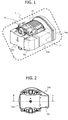
- Fig. 1 is an external perspective view of a motor direct-drive type scroll compressor 1 in this embodiment.
- the motor direct-drive type scroll compressor 1 mainly includes a body unit, and a motor unit for driving the same.
- the body unit has a body casing 15, a fixed scroll 7 to be described later, and a turning scroll 6 which is provided to face the fixed scroll 7 and makes a turning motion, and inflates or compresses the fluid.
- the motor unit has a shaft 3 and a motor casing 11 to be described later which are connected to the body unit and are drive shafts for driving the body unit, and a motor casing cooling fin 12 on an outer circumferential part of the motor casing 11.
- cooling air guiding members 10a, 10b, 10c, and 10d are provided for guiding cooling air generated by a cooling fin 8 to be described later and for cooling a turning scroll 6 and the fixed scroll 7, which will be described later.
- Fig. 2 is a front view of the motor direct-drive type scroll compressor 1
- Fig. 3 is a cross-sectional view taken from a position F-F of Fig. 2
- Fig. 4 is a front view of a state in which the cooling air guiding member is detached, and illustrates a structural view of a fixed scroll cooling fin 13.
- the shaft 3, a rotor 4 and the stator 5 of the motor direct-drive type scroll compressor 1 play a role of the motor, and by causing a current to flow through the stator 5, the rotor 4 and shaft 3 integrated with the rotor 4 turn.
- One end of the shaft 3 has an eccentric part which is a drive shaft for driving the turning scroll 6, and the turning scroll 6 is assembled to the eccentric part.
- the fixed scroll 7 is assembled to face the turning scroll 6, and the turning scroll 6 makes a turning motion with respect to the fixed scroll 7 by the rotation of the shaft 3.
- a spiral lap is provided on the end plate of the turning scroll 6 and the fixed scroll 7, and compresses the fluid by performing the aforementioned turning motion.
- a cooling fin 8 is provided at the other end of the eccentric part of the shaft. Cooling air guiding members 10a, 10b, 10c, and 10d for cooling the turning scroll 6 and the fixed scroll 7 by causing the cooling air to flow as illustrated by an arrow 9 are provided. That is, the outer circumferential surface of the motor unit is cooled by the cooling air flowing toward the cooling fin 8 from the body unit side, and the outer circumferential surface of the motor unit is cooled by the cooling air flowing from the cooling fin 8 toward the body unit side.
- the motor casing cooling fin 12 illustrated in Fig. 1 and the fixed scroll cooling fin 13 and a turning scroll cooling fin 14 illustrated in Fig. 3 are provided on the outer circumferential portion of the motor casing 11 for holding the stator 5, the fixed scroll 7 and the turning scroll 6.
- a turning bearing that supports the drive shaft with respect to the turning scroll 6 is disposed on a side closer to the motor unit than the end plate of the turning scroll 6.
- the rotor 4 and the stator 5 are configured to face each other in the axial direction. As a result, the axial dimension can be reduced.
- the body unit and the motor unit are attachably and detachably fastened between the body casing 15 and the motor casing 11 by a fastening member.
- the radial dimension of the motor casing 11 is made longer than the axial dimension, it is possible to reduce the axial dimension, and at the same time, to secure the cooling area.
- ⁇ a horizontal dimension (a radial dimension of the end plate of the fixed scroll) of the fixed scroll cooling fin 13 with respect to the cooling air
- the motor direct-drive type scroll compressor generally has a motor efficiency higher than efficiency of the compressor body.
- An amount obtained by subtracting the efficiency component from input power is set as a loss, and since respective losses are proportional to respective heat generation amounts, the heat generation amount of the compressor body becomes greater than the heat generation amount of the motor.
- a relational formula between Qs and Qc has a relation of formula (3).
- the tip of the cooling fin of the motor casing is at least outside the outermost circumferential surface of the lap formed on the fixed scroll.
- formula (5) becomes formula (7). ⁇ / 4 + lc / 4 ⁇ ls ⁇ ⁇ / 4 + lc
- the present invention is not limited to the embodiments described above, but includes various modified examples.
- the scroll compressor has been described in the above embodiment, it may be, for example, a blower, a pump or the like other than the compressor, and may be a so-called scroll-type fluid machine.
- the above-described embodiments have been described in detail in order to explain the present invention in an easy-to-understand manner, and are not necessarily limited to those having all the configurations described.
Landscapes
- Engineering & Computer Science (AREA)
- Mechanical Engineering (AREA)
- General Engineering & Computer Science (AREA)
- Rotary Pumps (AREA)
- Applications Or Details Of Rotary Compressors (AREA)
- Structures Of Non-Positive Displacement Pumps (AREA)
Abstract
Description
- The present invention relates to a scroll-type fluid machine.
- In a compressor such as a scroll compressor, which is one type of scroll-type fluid machines, customer demand for space saving is high.
- As a background art of this technical field, there is
JP 2002-371977 A - Patent Document 1:
JP 2002-371977 A - In Patent Document 1, the motor and a scroll compressor body are set to a direct-drive type, and a bearing position of the scroll compressor body is disposed on a compression chamber side to reduce a size in an axial direction. However, in a motor direct-drive type scroll compressor of such a structure, in some cases, since a radial dimension of the motor is only about a half of a radial dimension of the body, a cooling area of a motor unit decreases, and since no cooling fins are formed, no consideration is given to heat dissipation at all, and it is not possible to use the scroll compressor under a high load such as heat generation of the motor. As the cooling area of each part of a compressor body unit and the motor unit is reduced in this way in order to reduce the size, since the temperature rises and the part is not used as a product, it is necessary to consider each heat radiation.
- In this regard, an object of the present invention is to provide a scroll-type fluid machine capable of reducing an axial length and reducing a size, without causing an imbalance between a compressor body unit and a motor unit in terms of dissipation of heat.
- In order to solve the above problem, the present invention provides, for example, a scroll-type fluid machine including: a body unit which has a fixed scroll having a lap formed on an end plate thereof, a turning scroll having a lap formed on an end plate thereof to face the lap of the fixed scroll, and a body casing which accommodates the fixed scroll and the turning scroll; and a motor unit which has a drive shaft connected to the body unit to drive the body unit, a rotor rotating integrally with the drive shaft, a stator which imparts a rotational force to the rotor, and a motor casing which accommodates the drive shaft, the rotor and the stator, in which a cooling fin is formed on a surface opposite to a surface on which the laps of the end plates of the fixed scroll and the turning scroll are formed, and when a radial dimension of the end plate of the fixed scroll is defined as α, an axial dimension from a tip of the cooling fin of the fixed scroll to a tip of the cooling fin of the turning scroll is defined as lc, and an axial dimension of the stator is defined as ls, a relation of α/16 + lc/4 ≤ ls ≤ α/4 + lc is satisfied.
- According to the present invention, it is possible to provide a scroll-type fluid machine capable of reducing an axial length without causing an imbalance between a body unit and a motor unit in terms of dissipation of heat.
-
-
Fig. 1 is an external perspective view of a motor direct-drive type scroll compressor in an embodiment. -
Fig. 2 is a front view of the motor direct-drive type scroll compressor in the embodiment. -
Fig. 3 is a cross-sectional view of the motor direct-drive type scroll compressor in the embodiment. -
Fig. 4 is a front view of the motor direct-drive type scroll compressor in a state in which a cooling air guiding member is removed. - Embodiments of the present invention will be described below with reference to the drawings. Incidentally, in the drawings for describing the embodiments, elements having the same functions are denoted by the same names and reference numerals, and the repetitive description thereof will not be provided.
- This embodiment will be described with reference to
Figs. 1, 2 ,3, and 4 . Incidentally, the present embodiment will be described by taking a motor direct-drive type scroll compressor which is one type of scroll-type fluid machines as an example. -
Fig. 1 is an external perspective view of a motor direct-drive type scroll compressor 1 in this embodiment. InFig. 1 , the motor direct-drive type scroll compressor 1 mainly includes a body unit, and a motor unit for driving the same. The body unit has abody casing 15, afixed scroll 7 to be described later, and a turning scroll 6 which is provided to face thefixed scroll 7 and makes a turning motion, and inflates or compresses the fluid. The motor unit has ashaft 3 and amotor casing 11 to be described later which are connected to the body unit and are drive shafts for driving the body unit, and a motorcasing cooling fin 12 on an outer circumferential part of themotor casing 11. Furthermore, coolingair guiding members cooling fin 8 to be described later and for cooling a turning scroll 6 and thefixed scroll 7, which will be described later. -
Fig. 2 is a front view of the motor direct-drive type scroll compressor 1, andFig. 3 is a cross-sectional view taken from a position F-F ofFig. 2 .Fig. 4 is a front view of a state in which the cooling air guiding member is detached, and illustrates a structural view of a fixedscroll cooling fin 13. - In
Fig. 3 , theshaft 3, arotor 4 and thestator 5 of the motor direct-drive type scroll compressor 1 play a role of the motor, and by causing a current to flow through thestator 5, therotor 4 andshaft 3 integrated with therotor 4 turn. One end of theshaft 3 has an eccentric part which is a drive shaft for driving the turning scroll 6, and the turning scroll 6 is assembled to the eccentric part. Further, thefixed scroll 7 is assembled to face the turning scroll 6, and the turning scroll 6 makes a turning motion with respect to thefixed scroll 7 by the rotation of theshaft 3. A spiral lap is provided on the end plate of the turning scroll 6 and thefixed scroll 7, and compresses the fluid by performing the aforementioned turning motion. In order to cool thestator 5 that generates heat to cause the flow of electric current, and the turning scroll 6 and thefixed scroll 7 that generate heat to compress fluid, acooling fin 8 is provided at the other end of the eccentric part of the shaft. Coolingair guiding members fixed scroll 7 by causing the cooling air to flow as illustrated by anarrow 9 are provided. That is, the outer circumferential surface of the motor unit is cooled by the cooling air flowing toward thecooling fin 8 from the body unit side, and the outer circumferential surface of the motor unit is cooled by the cooling air flowing from thecooling fin 8 toward the body unit side. - In order to improve the cooling efficiency, the motor
casing cooling fin 12 illustrated inFig. 1 , and the fixedscroll cooling fin 13 and a turningscroll cooling fin 14 illustrated inFig. 3 are provided on the outer circumferential portion of themotor casing 11 for holding thestator 5, thefixed scroll 7 and the turning scroll 6. - Further, a turning bearing that supports the drive shaft with respect to the turning scroll 6 is disposed on a side closer to the motor unit than the end plate of the turning scroll 6. As a result, compared with a shape in which the turning bearing enters into the end plate in order to reduce the axial dimension, even with the turning scroll 6 and the
fixed scroll 7 having the same diameter, a compression amount can be secured without reducing a compression chamber. - In addition, the
rotor 4 and thestator 5 are configured to face each other in the axial direction. As a result, the axial dimension can be reduced. - Further, the body unit and the motor unit are attachably and detachably fastened between the
body casing 15 and themotor casing 11 by a fastening member. - Further, by making the radial dimension of the
motor casing 11 longer than the axial dimension, it is possible to reduce the axial dimension, and at the same time, to secure the cooling area. - Here, in a case where cooling parts of the turning scroll 6, the
fixed scroll 7 and thestator 5, which are heating elements, are approximated to a cylinder, when an effective cooling area of a region A indicated by a dotted line and formed by the laps of thefixed scroll 7 and the turning scroll 6 and thecooling fins stator 5 and a fitting portion of themotor casing 11 with thestator 5 is defined as SB, SA and SB can be approximated by formulas (1) and (2).

- Here, α: a horizontal dimension (a radial dimension of the end plate of the fixed scroll) of the fixed
scroll cooling fin 13 with respect to the cooling air, - lc: a distance from the end surface of the turning
scroll cooling fin 14 to the end surface of the fixedscroll cooling fin 13, - Dm: a radial dimension of the motor casing (including cooling fin), and
- ls: an axial dimension of the stator.
- Furthermore, the motor direct-drive type scroll compressor generally has a motor efficiency higher than efficiency of the compressor body. An amount obtained by subtracting the efficiency component from input power is set as a loss, and since respective losses are proportional to respective heat generation amounts, the heat generation amount of the compressor body becomes greater than the heat generation amount of the motor. Here, in the motor direct-drive type scroll compressor of the present embodiment, since heat generation amounts Qc of the fixed scroll and the turning scroll are 10 to 40% with respect to the input of the motor, and a heat generation amount Qs of the stator is about is 10% with respect to the input of the motor, a relational formula between Qs and Qc has a relation of formula (3).

- In order to prevent heat dissipation between the body unit and the motor unit from becoming imbalanced, it is necessary to provide an area corresponding to formula (3), and thus the relation between SA and SB is set to a relation of formula (4).

- Therefore, the following formula (5) is derived from the formulas (1), (2) and (4).

- Here, the relation between α and Dm will be described. In the case of α > Dm, since a cooling air passage is complicated or the passage length needs to be lengthened, the pressure loss of the cooling air increases, the air flow rate decreases, and the cooling of the turning scroll and the fixed scroll deteriorates. Also, since Dm is reduced, ls increases and an overall axial dimension L increases. On the other hand, in the case of α < Dm, since the cooling air is difficult to flow to the
motor casing 11, the motor cooling deteriorates. Further, since the motor casing is large, it is necessary to adopt a structure of a cooling air guiding member to avoid this. As a result, the cooling air guiding member has a complicated shape, the pressure loss increases, and the cooling air volume decreases. For the above reasons, the relation between α and Dm is set to the relation of formula (6) .
- Since the approximation of formula (6) is established, the tip of the cooling fin of the motor casing is at least outside the outermost circumferential surface of the lap formed on the fixed scroll.
- Using formula (6), formula (5) becomes formula (7).

- Therefore, in the present embodiment, by setting α, lc, and ls to satisfy the formula (7), it is possible to provide a motor direct-drive type scroll compressor capable of equalizing the heat dissipation of the body unit and the motor unit and reducing the axial length. Therefore, miniaturization and temperature reduction of the motor direct-drive type scroll compressor can be attained at the same time, resulting in a customer merit.
- The present invention is not limited to the embodiments described above, but includes various modified examples. For example, although the scroll compressor has been described in the above embodiment, it may be, for example, a blower, a pump or the like other than the compressor, and may be a so-called scroll-type fluid machine. Furthermore, the above-described embodiments have been described in detail in order to explain the present invention in an easy-to-understand manner, and are not necessarily limited to those having all the configurations described.
-
- 1 Motor direct-drive type scroll compressor
- 3 Shaft
- 4 Rotor
- 5 Stator
- 6 Turning scroll
- 7 Fixed scroll
- 8 Cooling fin
- 9 Cooling air flow direction
- 10a, 10b, 10c, 10d Cooling air guiding member
- 11 Motor casing
- 12 Motor casing cooling fin
- 13 Fixed scroll cooling fin
- 14 Turning scroll cooling fin
- 15 Body casing
- α Cooling air flow including cooling fins and horizontal dimension
- lc Distance from end surface of fixed scroll cooling fin to end surface of turning scroll cooling fin
- Dm Radial dimension of motor casing (including cooling fin)
- ls Axial dimension of stator
- L Axial dimension of motor direct-type scroll compressor
Claims (9)
- A scroll-type fluid machine comprising:a body unit which has a fixed scroll having a lap formed on an end plate thereof, a turning scroll having a lap formed on an end plate thereof to face the lap of the fixed scroll, and a body casing which accommodates the fixed scroll and the turning scroll; anda motor unit which has a drive shaft connected to the body unit to drive the body unit, a rotor rotating integrally with the drive shaft, a stator which imparts a rotational force to the rotor, and a motor casing which accommodates the drive shaft, the rotor and the stator,wherein a cooling fin is formed on a surface opposite to a surface on which the laps of the end plates of the fixed scroll and the turning scroll are formed, and when a radial dimension of the end plate of the fixed scroll is defined as α, an axial dimension from a tip of the cooling fin of the fixed scroll to a tip of the cooling fin of the turning scroll is defined as lc, and an axial dimension of the stator is defined as ls,a relation of α/16 + lc/4 ≤ ls ≤ α/4 + lc is satisfied.
- The scroll-type fluid machine according to claim 1, wherein the cooling fin is formed on an outer side in the radial direction of the motor casing, and the tip of the cooling fin of the motor casing is disposed on the outer side in the radial direction than an outermost circumferential surface of the lap formed on the fixed scroll.
- The scroll-type fluid machine according to claim 1, wherein a turning bearing configured to support the drive shaft with respect to the turning scroll is disposed on a side closer to the motor unit than the end plate of the turning scroll.
- The scroll-type fluid machine according to claim 1, wherein a cooling fin is provided at an end portion of the drive shaft opposite to the body unit.
- The scroll-type fluid machine according to claim 4, wherein the outer circumferential surface of the motor unit is cooled by cooling air flowing from the body unit side to the cooling fin.
- The scroll-type fluid machine according to claim 4, wherein the outer circumferential surface of the motor unit is cooled by cooling air flowing from the cooling fin to the body unit side.
- The scroll-type fluid machine according to claim 1, wherein the rotor and the stator are axially opposed to each other.
- The scroll-type fluid machine according to claim 1, wherein the body unit and the motor unit are attachably and detachably fastened between the body casing and the motor casing by a fastening member.
- The scroll-type fluid machine according to claim 1, wherein the radial dimension of the motor casing is longer than the axial dimension.
Applications Claiming Priority (1)
| Application Number | Priority Date | Filing Date | Title |
|---|---|---|---|
| PCT/JP2016/072718 WO2018025338A1 (en) | 2016-08-03 | 2016-08-03 | Scroll-type fluid machine |
Publications (3)
| Publication Number | Publication Date |
|---|---|
| EP3495663A1 true EP3495663A1 (en) | 2019-06-12 |
| EP3495663A4 EP3495663A4 (en) | 2020-01-22 |
| EP3495663B1 EP3495663B1 (en) | 2024-04-24 |
Family
ID=61074043
Family Applications (1)
| Application Number | Title | Priority Date | Filing Date |
|---|---|---|---|
| EP16911599.5A Active EP3495663B1 (en) | 2016-08-03 | 2016-08-03 | Scroll-type fluid machine |
Country Status (6)
| Country | Link |
|---|---|
| US (1) | US10995752B2 (en) |
| EP (1) | EP3495663B1 (en) |
| JP (1) | JP6795597B2 (en) |
| KR (1) | KR102041229B1 (en) |
| CN (1) | CN108700068B (en) |
| WO (1) | WO2018025338A1 (en) |
Families Citing this family (2)
| Publication number | Priority date | Publication date | Assignee | Title |
|---|---|---|---|---|
| CN111818742A (en) * | 2020-07-06 | 2020-10-23 | 安徽智信大数据科技有限公司 | Data acquisition and processing device based on big data |
| CN116163956B (en) * | 2023-02-28 | 2024-11-22 | 江苏曼淇威电气产品有限公司 | Scroll compressor |
Family Cites Families (15)
| Publication number | Priority date | Publication date | Assignee | Title |
|---|---|---|---|---|
| JPH07247968A (en) | 1994-03-09 | 1995-09-26 | Daikin Ind Ltd | Scroll compressor |
| US5417554A (en) | 1994-07-19 | 1995-05-23 | Ingersoll-Rand Company | Air cooling system for scroll compressors |
| JP4026099B2 (en) | 1998-10-15 | 2007-12-26 | アネスト岩田株式会社 | Scroll fluid machinery |
| JP2002371977A (en) | 2001-06-13 | 2002-12-26 | Ebara Corp | Scroll fluid machine |
| JP2006029238A (en) * | 2004-07-16 | 2006-02-02 | Anest Iwata Corp | Rotary machine |
| JP2006097531A (en) * | 2004-09-29 | 2006-04-13 | Anest Iwata Corp | Turning scroll in scroll fluid machine |
| JP4629546B2 (en) * | 2005-09-30 | 2011-02-09 | アネスト岩田株式会社 | Scroll fluid machinery |
| JP2007321563A (en) * | 2006-05-30 | 2007-12-13 | Smc Corp | Fluid pump device |
| JP4835384B2 (en) * | 2006-10-26 | 2011-12-14 | ダイキン工業株式会社 | Compressor |
| US8177534B2 (en) * | 2008-10-30 | 2012-05-15 | Advanced Scroll Technologies (Hangzhou), Inc. | Scroll-type fluid displacement apparatus with improved cooling system |
| KR101141427B1 (en) * | 2009-04-27 | 2012-05-07 | 엘지전자 주식회사 | Scroll compressor |
| JP5986940B2 (en) * | 2013-02-27 | 2016-09-06 | 株式会社日立産機システム | Scroll type fluid machine |
| CN104500394A (en) * | 2014-12-24 | 2015-04-08 | 楼伟华 | Oil-free lubricatoin scroll compressor |
| WO2018011970A1 (en) * | 2016-07-15 | 2018-01-18 | 株式会社日立産機システム | Motor-integrated fluid machine |
| WO2018020651A1 (en) * | 2016-07-29 | 2018-02-01 | 株式会社日立産機システム | Scroll-type fluid machine and method for assembling same |
-
2016
- 2016-08-03 WO PCT/JP2016/072718 patent/WO2018025338A1/en not_active Ceased
- 2016-08-03 EP EP16911599.5A patent/EP3495663B1/en active Active
- 2016-08-03 CN CN201680082555.2A patent/CN108700068B/en active Active
- 2016-08-03 JP JP2018531024A patent/JP6795597B2/en active Active
- 2016-08-03 US US16/083,974 patent/US10995752B2/en active Active
- 2016-08-03 KR KR1020187024290A patent/KR102041229B1/en active Active
Also Published As
| Publication number | Publication date |
|---|---|
| JPWO2018025338A1 (en) | 2018-12-20 |
| KR20180105201A (en) | 2018-09-27 |
| EP3495663B1 (en) | 2024-04-24 |
| EP3495663A4 (en) | 2020-01-22 |
| CN108700068B (en) | 2020-06-19 |
| KR102041229B1 (en) | 2019-11-06 |
| US10995752B2 (en) | 2021-05-04 |
| WO2018025338A1 (en) | 2018-02-08 |
| CN108700068A (en) | 2018-10-23 |
| JP6795597B2 (en) | 2020-12-09 |
| US20200291939A1 (en) | 2020-09-17 |
Similar Documents
| Publication | Publication Date | Title |
|---|---|---|
| US10389216B2 (en) | Stator applicable to a single-phase or polyphase motor, motor comprising the stator and compressor comprising the motor or the stator | |
| CN104514718B (en) | Convolute-hydrodynamic mechanics | |
| CN104895807B (en) | Centrifugal compressor | |
| EP2980409A1 (en) | Scroll-type fluid machine | |
| JP2017129152A (en) | Housing for scroll compressor fan | |
| CN100439715C (en) | electric compressor | |
| US10995752B2 (en) | Scroll-type fluid machine | |
| JP2018110483A (en) | Permanent magnet type rotary electric machine, and compressor using the same | |
| JP2016100927A (en) | Permanent magnet type rotating electric machine and compressor using the same | |
| JP6470598B2 (en) | Permanent magnet type rotating electric machine and compressor using the same | |
| EP3578822B1 (en) | Scroll compressor | |
| JP2010038154A (en) | Line fed permanent magnet synchronous type motor used for scroll compressor with bypass port | |
| JP7005728B2 (en) | Scrolling fluid machine | |
| CN113482923B (en) | Compression assembly, scroll compressor and air conditioner | |
| JP2002209354A (en) | High-speed motor / generator | |
| KR20200112274A (en) | Scroll-type compressor | |
| CN215633773U (en) | Rotor subassembly, compressor and air conditioner | |
| US20240011487A1 (en) | Scroll fluid machine | |
| EP3480469B1 (en) | Screw compressor | |
| JP2003047220A (en) | Three-phase induction motor and motor integrated fluid pressure generator | |
| CN222620871U (en) | Disk motor, fluid machine, motor main body and rotating assembly | |
| CN104632620B (en) | Compressor | |
| CN214464886U (en) | Scroll compression and expansion integrated machine | |
| CN107165827B (en) | Compressor with a compressor housing having a plurality of compressor blades | |
| CN102213217A (en) | Scroll compressor |
Legal Events
| Date | Code | Title | Description |
|---|---|---|---|
| STAA | Information on the status of an ep patent application or granted ep patent |
Free format text: STATUS: THE INTERNATIONAL PUBLICATION HAS BEEN MADE |
|
| PUAI | Public reference made under article 153(3) epc to a published international application that has entered the european phase |
Free format text: ORIGINAL CODE: 0009012 |
|
| STAA | Information on the status of an ep patent application or granted ep patent |
Free format text: STATUS: REQUEST FOR EXAMINATION WAS MADE |
|
| 17P | Request for examination filed |
Effective date: 20190304 |
|
| AK | Designated contracting states |
Kind code of ref document: A1 Designated state(s): AL AT BE BG CH CY CZ DE DK EE ES FI FR GB GR HR HU IE IS IT LI LT LU LV MC MK MT NL NO PL PT RO RS SE SI SK SM TR |
|
| AX | Request for extension of the european patent |
Extension state: BA ME |
|
| DAV | Request for validation of the european patent (deleted) | ||
| DAX | Request for extension of the european patent (deleted) | ||
| A4 | Supplementary search report drawn up and despatched |
Effective date: 20200107 |
|
| RIC1 | Information provided on ipc code assigned before grant |
Ipc: F04C 18/02 20060101AFI20191219BHEP Ipc: F04B 39/06 20060101ALI20191219BHEP Ipc: F04C 29/00 20060101ALI20191219BHEP Ipc: F04C 29/04 20060101ALI20191219BHEP |
|
| STAA | Information on the status of an ep patent application or granted ep patent |
Free format text: STATUS: EXAMINATION IS IN PROGRESS |
|
| 17Q | First examination report despatched |
Effective date: 20220510 |
|
| GRAP | Despatch of communication of intention to grant a patent |
Free format text: ORIGINAL CODE: EPIDOSNIGR1 |
|
| STAA | Information on the status of an ep patent application or granted ep patent |
Free format text: STATUS: GRANT OF PATENT IS INTENDED |
|
| INTG | Intention to grant announced |
Effective date: 20231117 |
|
| GRAS | Grant fee paid |
Free format text: ORIGINAL CODE: EPIDOSNIGR3 |
|
| GRAA | (expected) grant |
Free format text: ORIGINAL CODE: 0009210 |
|
| STAA | Information on the status of an ep patent application or granted ep patent |
Free format text: STATUS: THE PATENT HAS BEEN GRANTED |
|
| AK | Designated contracting states |
Kind code of ref document: B1 Designated state(s): AL AT BE BG CH CY CZ DE DK EE ES FI FR GB GR HR HU IE IS IT LI LT LU LV MC MK MT NL NO PL PT RO RS SE SI SK SM TR |
|
| REG | Reference to a national code |
Ref country code: GB Ref legal event code: FG4D |
|
| REG | Reference to a national code |
Ref country code: CH Ref legal event code: EP |
|
| REG | Reference to a national code |
Ref country code: DE Ref legal event code: R096 Ref document number: 602016087187 Country of ref document: DE |
|
| REG | Reference to a national code |
Ref country code: IE Ref legal event code: FG4D |
|
| REG | Reference to a national code |
Ref country code: LT Ref legal event code: MG9D |
|
| REG | Reference to a national code |
Ref country code: NL Ref legal event code: MP Effective date: 20240424 |
|
| REG | Reference to a national code |
Ref country code: AT Ref legal event code: MK05 Ref document number: 1679873 Country of ref document: AT Kind code of ref document: T Effective date: 20240424 |
|
| PG25 | Lapsed in a contracting state [announced via postgrant information from national office to epo] |
Ref country code: NL Free format text: LAPSE BECAUSE OF FAILURE TO SUBMIT A TRANSLATION OF THE DESCRIPTION OR TO PAY THE FEE WITHIN THE PRESCRIBED TIME-LIMIT Effective date: 20240424 |
|
| PG25 | Lapsed in a contracting state [announced via postgrant information from national office to epo] |
Ref country code: NL Free format text: LAPSE BECAUSE OF FAILURE TO SUBMIT A TRANSLATION OF THE DESCRIPTION OR TO PAY THE FEE WITHIN THE PRESCRIBED TIME-LIMIT Effective date: 20240424 |
|
| PG25 | Lapsed in a contracting state [announced via postgrant information from national office to epo] |
Ref country code: IS Free format text: LAPSE BECAUSE OF FAILURE TO SUBMIT A TRANSLATION OF THE DESCRIPTION OR TO PAY THE FEE WITHIN THE PRESCRIBED TIME-LIMIT Effective date: 20240824 |
|
| PG25 | Lapsed in a contracting state [announced via postgrant information from national office to epo] |
Ref country code: BG Free format text: LAPSE BECAUSE OF FAILURE TO SUBMIT A TRANSLATION OF THE DESCRIPTION OR TO PAY THE FEE WITHIN THE PRESCRIBED TIME-LIMIT Effective date: 20240424 |
|
| PG25 | Lapsed in a contracting state [announced via postgrant information from national office to epo] |
Ref country code: HR Free format text: LAPSE BECAUSE OF FAILURE TO SUBMIT A TRANSLATION OF THE DESCRIPTION OR TO PAY THE FEE WITHIN THE PRESCRIBED TIME-LIMIT Effective date: 20240424 Ref country code: FI Free format text: LAPSE BECAUSE OF FAILURE TO SUBMIT A TRANSLATION OF THE DESCRIPTION OR TO PAY THE FEE WITHIN THE PRESCRIBED TIME-LIMIT Effective date: 20240424 |
|
| PG25 | Lapsed in a contracting state [announced via postgrant information from national office to epo] |
Ref country code: GR Free format text: LAPSE BECAUSE OF FAILURE TO SUBMIT A TRANSLATION OF THE DESCRIPTION OR TO PAY THE FEE WITHIN THE PRESCRIBED TIME-LIMIT Effective date: 20240725 |
|
| PG25 | Lapsed in a contracting state [announced via postgrant information from national office to epo] |
Ref country code: PT Free format text: LAPSE BECAUSE OF FAILURE TO SUBMIT A TRANSLATION OF THE DESCRIPTION OR TO PAY THE FEE WITHIN THE PRESCRIBED TIME-LIMIT Effective date: 20240826 |
|
| PG25 | Lapsed in a contracting state [announced via postgrant information from national office to epo] |
Ref country code: ES Free format text: LAPSE BECAUSE OF FAILURE TO SUBMIT A TRANSLATION OF THE DESCRIPTION OR TO PAY THE FEE WITHIN THE PRESCRIBED TIME-LIMIT Effective date: 20240424 |
|
| PG25 | Lapsed in a contracting state [announced via postgrant information from national office to epo] |
Ref country code: AT Free format text: LAPSE BECAUSE OF FAILURE TO SUBMIT A TRANSLATION OF THE DESCRIPTION OR TO PAY THE FEE WITHIN THE PRESCRIBED TIME-LIMIT Effective date: 20240424 |
|
| PG25 | Lapsed in a contracting state [announced via postgrant information from national office to epo] |
Ref country code: PL Free format text: LAPSE BECAUSE OF FAILURE TO SUBMIT A TRANSLATION OF THE DESCRIPTION OR TO PAY THE FEE WITHIN THE PRESCRIBED TIME-LIMIT Effective date: 20240424 |
|
| PG25 | Lapsed in a contracting state [announced via postgrant information from national office to epo] |
Ref country code: LV Free format text: LAPSE BECAUSE OF FAILURE TO SUBMIT A TRANSLATION OF THE DESCRIPTION OR TO PAY THE FEE WITHIN THE PRESCRIBED TIME-LIMIT Effective date: 20240424 |
|
| PG25 | Lapsed in a contracting state [announced via postgrant information from national office to epo] |
Ref country code: PT Free format text: LAPSE BECAUSE OF FAILURE TO SUBMIT A TRANSLATION OF THE DESCRIPTION OR TO PAY THE FEE WITHIN THE PRESCRIBED TIME-LIMIT Effective date: 20240826 Ref country code: PL Free format text: LAPSE BECAUSE OF FAILURE TO SUBMIT A TRANSLATION OF THE DESCRIPTION OR TO PAY THE FEE WITHIN THE PRESCRIBED TIME-LIMIT Effective date: 20240424 Ref country code: NO Free format text: LAPSE BECAUSE OF FAILURE TO SUBMIT A TRANSLATION OF THE DESCRIPTION OR TO PAY THE FEE WITHIN THE PRESCRIBED TIME-LIMIT Effective date: 20240724 Ref country code: LV Free format text: LAPSE BECAUSE OF FAILURE TO SUBMIT A TRANSLATION OF THE DESCRIPTION OR TO PAY THE FEE WITHIN THE PRESCRIBED TIME-LIMIT Effective date: 20240424 Ref country code: IS Free format text: LAPSE BECAUSE OF FAILURE TO SUBMIT A TRANSLATION OF THE DESCRIPTION OR TO PAY THE FEE WITHIN THE PRESCRIBED TIME-LIMIT Effective date: 20240824 Ref country code: HR Free format text: LAPSE BECAUSE OF FAILURE TO SUBMIT A TRANSLATION OF THE DESCRIPTION OR TO PAY THE FEE WITHIN THE PRESCRIBED TIME-LIMIT Effective date: 20240424 Ref country code: GR Free format text: LAPSE BECAUSE OF FAILURE TO SUBMIT A TRANSLATION OF THE DESCRIPTION OR TO PAY THE FEE WITHIN THE PRESCRIBED TIME-LIMIT Effective date: 20240725 Ref country code: FI Free format text: LAPSE BECAUSE OF FAILURE TO SUBMIT A TRANSLATION OF THE DESCRIPTION OR TO PAY THE FEE WITHIN THE PRESCRIBED TIME-LIMIT Effective date: 20240424 Ref country code: ES Free format text: LAPSE BECAUSE OF FAILURE TO SUBMIT A TRANSLATION OF THE DESCRIPTION OR TO PAY THE FEE WITHIN THE PRESCRIBED TIME-LIMIT Effective date: 20240424 Ref country code: BG Free format text: LAPSE BECAUSE OF FAILURE TO SUBMIT A TRANSLATION OF THE DESCRIPTION OR TO PAY THE FEE WITHIN THE PRESCRIBED TIME-LIMIT Effective date: 20240424 Ref country code: AT Free format text: LAPSE BECAUSE OF FAILURE TO SUBMIT A TRANSLATION OF THE DESCRIPTION OR TO PAY THE FEE WITHIN THE PRESCRIBED TIME-LIMIT Effective date: 20240424 Ref country code: RS Free format text: LAPSE BECAUSE OF FAILURE TO SUBMIT A TRANSLATION OF THE DESCRIPTION OR TO PAY THE FEE WITHIN THE PRESCRIBED TIME-LIMIT Effective date: 20240724 |
|
| PG25 | Lapsed in a contracting state [announced via postgrant information from national office to epo] |
Ref country code: DK Free format text: LAPSE BECAUSE OF FAILURE TO SUBMIT A TRANSLATION OF THE DESCRIPTION OR TO PAY THE FEE WITHIN THE PRESCRIBED TIME-LIMIT Effective date: 20240424 |
|
| PG25 | Lapsed in a contracting state [announced via postgrant information from national office to epo] |
Ref country code: EE Free format text: LAPSE BECAUSE OF FAILURE TO SUBMIT A TRANSLATION OF THE DESCRIPTION OR TO PAY THE FEE WITHIN THE PRESCRIBED TIME-LIMIT Effective date: 20240424 |
|
| PG25 | Lapsed in a contracting state [announced via postgrant information from national office to epo] |
Ref country code: CZ Free format text: LAPSE BECAUSE OF FAILURE TO SUBMIT A TRANSLATION OF THE DESCRIPTION OR TO PAY THE FEE WITHIN THE PRESCRIBED TIME-LIMIT Effective date: 20240424 |
|
| PG25 | Lapsed in a contracting state [announced via postgrant information from national office to epo] |
Ref country code: SK Free format text: LAPSE BECAUSE OF FAILURE TO SUBMIT A TRANSLATION OF THE DESCRIPTION OR TO PAY THE FEE WITHIN THE PRESCRIBED TIME-LIMIT Effective date: 20240424 Ref country code: RO Free format text: LAPSE BECAUSE OF FAILURE TO SUBMIT A TRANSLATION OF THE DESCRIPTION OR TO PAY THE FEE WITHIN THE PRESCRIBED TIME-LIMIT Effective date: 20240424 |
|
| REG | Reference to a national code |
Ref country code: DE Ref legal event code: R097 Ref document number: 602016087187 Country of ref document: DE |
|
| PG25 | Lapsed in a contracting state [announced via postgrant information from national office to epo] |
Ref country code: SM Free format text: LAPSE BECAUSE OF FAILURE TO SUBMIT A TRANSLATION OF THE DESCRIPTION OR TO PAY THE FEE WITHIN THE PRESCRIBED TIME-LIMIT Effective date: 20240424 |
|
| PG25 | Lapsed in a contracting state [announced via postgrant information from national office to epo] |
Ref country code: SM Free format text: LAPSE BECAUSE OF FAILURE TO SUBMIT A TRANSLATION OF THE DESCRIPTION OR TO PAY THE FEE WITHIN THE PRESCRIBED TIME-LIMIT Effective date: 20240424 Ref country code: SK Free format text: LAPSE BECAUSE OF FAILURE TO SUBMIT A TRANSLATION OF THE DESCRIPTION OR TO PAY THE FEE WITHIN THE PRESCRIBED TIME-LIMIT Effective date: 20240424 Ref country code: RO Free format text: LAPSE BECAUSE OF FAILURE TO SUBMIT A TRANSLATION OF THE DESCRIPTION OR TO PAY THE FEE WITHIN THE PRESCRIBED TIME-LIMIT Effective date: 20240424 Ref country code: EE Free format text: LAPSE BECAUSE OF FAILURE TO SUBMIT A TRANSLATION OF THE DESCRIPTION OR TO PAY THE FEE WITHIN THE PRESCRIBED TIME-LIMIT Effective date: 20240424 Ref country code: DK Free format text: LAPSE BECAUSE OF FAILURE TO SUBMIT A TRANSLATION OF THE DESCRIPTION OR TO PAY THE FEE WITHIN THE PRESCRIBED TIME-LIMIT Effective date: 20240424 Ref country code: CZ Free format text: LAPSE BECAUSE OF FAILURE TO SUBMIT A TRANSLATION OF THE DESCRIPTION OR TO PAY THE FEE WITHIN THE PRESCRIBED TIME-LIMIT Effective date: 20240424 |
|
| PLBE | No opposition filed within time limit |
Free format text: ORIGINAL CODE: 0009261 |
|
| STAA | Information on the status of an ep patent application or granted ep patent |
Free format text: STATUS: NO OPPOSITION FILED WITHIN TIME LIMIT |
|
| REG | Reference to a national code |
Ref country code: CH Ref legal event code: PL |
|
| 26N | No opposition filed |
Effective date: 20250127 |
|
| PG25 | Lapsed in a contracting state [announced via postgrant information from national office to epo] |
Ref country code: LU Free format text: LAPSE BECAUSE OF NON-PAYMENT OF DUE FEES Effective date: 20240803 |
|
| PG25 | Lapsed in a contracting state [announced via postgrant information from national office to epo] |
Ref country code: SI Free format text: LAPSE BECAUSE OF FAILURE TO SUBMIT A TRANSLATION OF THE DESCRIPTION OR TO PAY THE FEE WITHIN THE PRESCRIBED TIME-LIMIT Effective date: 20240424 Ref country code: CH Free format text: LAPSE BECAUSE OF NON-PAYMENT OF DUE FEES Effective date: 20240831 Ref country code: MC Free format text: LAPSE BECAUSE OF FAILURE TO SUBMIT A TRANSLATION OF THE DESCRIPTION OR TO PAY THE FEE WITHIN THE PRESCRIBED TIME-LIMIT Effective date: 20240424 |
|
| PG25 | Lapsed in a contracting state [announced via postgrant information from national office to epo] |
Ref country code: IE Free format text: LAPSE BECAUSE OF NON-PAYMENT OF DUE FEES Effective date: 20240803 |
|
| PG25 | Lapsed in a contracting state [announced via postgrant information from national office to epo] |
Ref country code: SE Free format text: LAPSE BECAUSE OF FAILURE TO SUBMIT A TRANSLATION OF THE DESCRIPTION OR TO PAY THE FEE WITHIN THE PRESCRIBED TIME-LIMIT Effective date: 20240424 |
|
| PGFP | Annual fee paid to national office [announced via postgrant information from national office to epo] |
Ref country code: DE Payment date: 20250831 Year of fee payment: 10 |
|
| PGFP | Annual fee paid to national office [announced via postgrant information from national office to epo] |
Ref country code: BE Payment date: 20250820 Year of fee payment: 10 Ref country code: GB Payment date: 20250822 Year of fee payment: 10 |
|
| PGFP | Annual fee paid to national office [announced via postgrant information from national office to epo] |
Ref country code: FR Payment date: 20250827 Year of fee payment: 10 |
|
| PG25 | Lapsed in a contracting state [announced via postgrant information from national office to epo] |
Ref country code: IT Free format text: LAPSE BECAUSE OF FAILURE TO SUBMIT A TRANSLATION OF THE DESCRIPTION OR TO PAY THE FEE WITHIN THE PRESCRIBED TIME-LIMIT Effective date: 20240424 Ref country code: CY Free format text: LAPSE BECAUSE OF FAILURE TO SUBMIT A TRANSLATION OF THE DESCRIPTION OR TO PAY THE FEE WITHIN THE PRESCRIBED TIME-LIMIT; INVALID AB INITIO Effective date: 20160803 |
|
| PG25 | Lapsed in a contracting state [announced via postgrant information from national office to epo] |
Ref country code: HU Free format text: LAPSE BECAUSE OF FAILURE TO SUBMIT A TRANSLATION OF THE DESCRIPTION OR TO PAY THE FEE WITHIN THE PRESCRIBED TIME-LIMIT; INVALID AB INITIO Effective date: 20160803 |