EP3495534A1 - Long substrate treatment apparatus and treatment method - Google Patents
Long substrate treatment apparatus and treatment method Download PDFInfo
- Publication number
- EP3495534A1 EP3495534A1 EP18204550.0A EP18204550A EP3495534A1 EP 3495534 A1 EP3495534 A1 EP 3495534A1 EP 18204550 A EP18204550 A EP 18204550A EP 3495534 A1 EP3495534 A1 EP 3495534A1
- Authority
- EP
- European Patent Office
- Prior art keywords
- roll
- tension
- outfeed
- infeed
- long substrate
- Prior art date
- Legal status (The legal status is an assumption and is not a legal conclusion. Google has not performed a legal analysis and makes no representation as to the accuracy of the status listed.)
- Granted
Links
Images





Classifications
-
- C—CHEMISTRY; METALLURGY
- C23—COATING METALLIC MATERIAL; COATING MATERIAL WITH METALLIC MATERIAL; CHEMICAL SURFACE TREATMENT; DIFFUSION TREATMENT OF METALLIC MATERIAL; COATING BY VACUUM EVAPORATION, BY SPUTTERING, BY ION IMPLANTATION OR BY CHEMICAL VAPOUR DEPOSITION, IN GENERAL; INHIBITING CORROSION OF METALLIC MATERIAL OR INCRUSTATION IN GENERAL
- C23C—COATING METALLIC MATERIAL; COATING MATERIAL WITH METALLIC MATERIAL; SURFACE TREATMENT OF METALLIC MATERIAL BY DIFFUSION INTO THE SURFACE, BY CHEMICAL CONVERSION OR SUBSTITUTION; COATING BY VACUUM EVAPORATION, BY SPUTTERING, BY ION IMPLANTATION OR BY CHEMICAL VAPOUR DEPOSITION, IN GENERAL
- C23C14/00—Coating by vacuum evaporation, by sputtering or by ion implantation of the coating forming material
- C23C14/22—Coating by vacuum evaporation, by sputtering or by ion implantation of the coating forming material characterised by the process of coating
- C23C14/56—Apparatus specially adapted for continuous coating; Arrangements for maintaining the vacuum, e.g. vacuum locks
- C23C14/562—Apparatus specially adapted for continuous coating; Arrangements for maintaining the vacuum, e.g. vacuum locks for coating elongated substrates
-
- B—PERFORMING OPERATIONS; TRANSPORTING
- B65—CONVEYING; PACKING; STORING; HANDLING THIN OR FILAMENTARY MATERIAL
- B65H—HANDLING THIN OR FILAMENTARY MATERIAL, e.g. SHEETS, WEBS, CABLES
- B65H23/00—Registering, tensioning, smoothing or guiding webs
- B65H23/04—Registering, tensioning, smoothing or guiding webs longitudinally
- B65H23/18—Registering, tensioning, smoothing or guiding webs longitudinally by controlling or regulating the web-advancing mechanism, e.g. mechanism acting on the running web
- B65H23/188—Registering, tensioning, smoothing or guiding webs longitudinally by controlling or regulating the web-advancing mechanism, e.g. mechanism acting on the running web in connection with running-web
- B65H23/1888—Registering, tensioning, smoothing or guiding webs longitudinally by controlling or regulating the web-advancing mechanism, e.g. mechanism acting on the running web in connection with running-web and controlling web tension
-
- C—CHEMISTRY; METALLURGY
- C23—COATING METALLIC MATERIAL; COATING MATERIAL WITH METALLIC MATERIAL; CHEMICAL SURFACE TREATMENT; DIFFUSION TREATMENT OF METALLIC MATERIAL; COATING BY VACUUM EVAPORATION, BY SPUTTERING, BY ION IMPLANTATION OR BY CHEMICAL VAPOUR DEPOSITION, IN GENERAL; INHIBITING CORROSION OF METALLIC MATERIAL OR INCRUSTATION IN GENERAL
- C23C—COATING METALLIC MATERIAL; COATING MATERIAL WITH METALLIC MATERIAL; SURFACE TREATMENT OF METALLIC MATERIAL BY DIFFUSION INTO THE SURFACE, BY CHEMICAL CONVERSION OR SUBSTITUTION; COATING BY VACUUM EVAPORATION, BY SPUTTERING, BY ION IMPLANTATION OR BY CHEMICAL VAPOUR DEPOSITION, IN GENERAL
- C23C14/00—Coating by vacuum evaporation, by sputtering or by ion implantation of the coating forming material
- C23C14/06—Coating by vacuum evaporation, by sputtering or by ion implantation of the coating forming material characterised by the coating material
- C23C14/14—Metallic material, boron or silicon
- C23C14/20—Metallic material, boron or silicon on organic substrates
- C23C14/205—Metallic material, boron or silicon on organic substrates by cathodic sputtering
-
- C—CHEMISTRY; METALLURGY
- C23—COATING METALLIC MATERIAL; COATING MATERIAL WITH METALLIC MATERIAL; CHEMICAL SURFACE TREATMENT; DIFFUSION TREATMENT OF METALLIC MATERIAL; COATING BY VACUUM EVAPORATION, BY SPUTTERING, BY ION IMPLANTATION OR BY CHEMICAL VAPOUR DEPOSITION, IN GENERAL; INHIBITING CORROSION OF METALLIC MATERIAL OR INCRUSTATION IN GENERAL
- C23C—COATING METALLIC MATERIAL; COATING MATERIAL WITH METALLIC MATERIAL; SURFACE TREATMENT OF METALLIC MATERIAL BY DIFFUSION INTO THE SURFACE, BY CHEMICAL CONVERSION OR SUBSTITUTION; COATING BY VACUUM EVAPORATION, BY SPUTTERING, BY ION IMPLANTATION OR BY CHEMICAL VAPOUR DEPOSITION, IN GENERAL
- C23C14/00—Coating by vacuum evaporation, by sputtering or by ion implantation of the coating forming material
- C23C14/22—Coating by vacuum evaporation, by sputtering or by ion implantation of the coating forming material characterised by the process of coating
- C23C14/34—Sputtering
- C23C14/35—Sputtering by application of a magnetic field, e.g. magnetron sputtering
- C23C14/352—Sputtering by application of a magnetic field, e.g. magnetron sputtering using more than one target
-
- C—CHEMISTRY; METALLURGY
- C23—COATING METALLIC MATERIAL; COATING MATERIAL WITH METALLIC MATERIAL; CHEMICAL SURFACE TREATMENT; DIFFUSION TREATMENT OF METALLIC MATERIAL; COATING BY VACUUM EVAPORATION, BY SPUTTERING, BY ION IMPLANTATION OR BY CHEMICAL VAPOUR DEPOSITION, IN GENERAL; INHIBITING CORROSION OF METALLIC MATERIAL OR INCRUSTATION IN GENERAL
- C23C—COATING METALLIC MATERIAL; COATING MATERIAL WITH METALLIC MATERIAL; SURFACE TREATMENT OF METALLIC MATERIAL BY DIFFUSION INTO THE SURFACE, BY CHEMICAL CONVERSION OR SUBSTITUTION; COATING BY VACUUM EVAPORATION, BY SPUTTERING, BY ION IMPLANTATION OR BY CHEMICAL VAPOUR DEPOSITION, IN GENERAL
- C23C14/00—Coating by vacuum evaporation, by sputtering or by ion implantation of the coating forming material
- C23C14/22—Coating by vacuum evaporation, by sputtering or by ion implantation of the coating forming material characterised by the process of coating
- C23C14/50—Substrate holders
-
- C—CHEMISTRY; METALLURGY
- C23—COATING METALLIC MATERIAL; COATING MATERIAL WITH METALLIC MATERIAL; CHEMICAL SURFACE TREATMENT; DIFFUSION TREATMENT OF METALLIC MATERIAL; COATING BY VACUUM EVAPORATION, BY SPUTTERING, BY ION IMPLANTATION OR BY CHEMICAL VAPOUR DEPOSITION, IN GENERAL; INHIBITING CORROSION OF METALLIC MATERIAL OR INCRUSTATION IN GENERAL
- C23C—COATING METALLIC MATERIAL; COATING MATERIAL WITH METALLIC MATERIAL; SURFACE TREATMENT OF METALLIC MATERIAL BY DIFFUSION INTO THE SURFACE, BY CHEMICAL CONVERSION OR SUBSTITUTION; COATING BY VACUUM EVAPORATION, BY SPUTTERING, BY ION IMPLANTATION OR BY CHEMICAL VAPOUR DEPOSITION, IN GENERAL
- C23C14/00—Coating by vacuum evaporation, by sputtering or by ion implantation of the coating forming material
- C23C14/22—Coating by vacuum evaporation, by sputtering or by ion implantation of the coating forming material characterised by the process of coating
- C23C14/54—Controlling or regulating the coating process
- C23C14/541—Heating or cooling of the substrates
-
- H—ELECTRICITY
- H01—ELECTRIC ELEMENTS
- H01J—ELECTRIC DISCHARGE TUBES OR DISCHARGE LAMPS
- H01J37/00—Discharge tubes with provision for introducing objects or material to be exposed to the discharge, e.g. for the purpose of examination or processing thereof
- H01J37/32—Gas-filled discharge tubes
- H01J37/32431—Constructional details of the reactor
- H01J37/3244—Gas supply means
-
- H—ELECTRICITY
- H01—ELECTRIC ELEMENTS
- H01J—ELECTRIC DISCHARGE TUBES OR DISCHARGE LAMPS
- H01J37/00—Discharge tubes with provision for introducing objects or material to be exposed to the discharge, e.g. for the purpose of examination or processing thereof
- H01J37/32—Gas-filled discharge tubes
- H01J37/32431—Constructional details of the reactor
- H01J37/32733—Means for moving the material to be treated
- H01J37/32752—Means for moving the material to be treated for moving the material across the discharge
- H01J37/32761—Continuous moving
- H01J37/3277—Continuous moving of continuous material
-
- H—ELECTRICITY
- H01—ELECTRIC ELEMENTS
- H01J—ELECTRIC DISCHARGE TUBES OR DISCHARGE LAMPS
- H01J37/00—Discharge tubes with provision for introducing objects or material to be exposed to the discharge, e.g. for the purpose of examination or processing thereof
- H01J37/32—Gas-filled discharge tubes
- H01J37/34—Gas-filled discharge tubes operating with cathodic sputtering
- H01J37/3402—Gas-filled discharge tubes operating with cathodic sputtering using supplementary magnetic fields
- H01J37/3405—Magnetron sputtering
-
- B—PERFORMING OPERATIONS; TRANSPORTING
- B65—CONVEYING; PACKING; STORING; HANDLING THIN OR FILAMENTARY MATERIAL
- B65H—HANDLING THIN OR FILAMENTARY MATERIAL, e.g. SHEETS, WEBS, CABLES
- B65H2301/00—Handling processes for sheets or webs
- B65H2301/50—Auxiliary process performed during handling process
- B65H2301/51—Modifying a characteristic of handled material
- B65H2301/511—Processing surface of handled material upon transport or guiding thereof, e.g. cleaning
- B65H2301/5114—Processing surface of handled material upon transport or guiding thereof, e.g. cleaning coating
- B65H2301/51145—Processing surface of handled material upon transport or guiding thereof, e.g. cleaning coating by vapour deposition
-
- B—PERFORMING OPERATIONS; TRANSPORTING
- B65—CONVEYING; PACKING; STORING; HANDLING THIN OR FILAMENTARY MATERIAL
- B65H—HANDLING THIN OR FILAMENTARY MATERIAL, e.g. SHEETS, WEBS, CABLES
- B65H2301/00—Handling processes for sheets or webs
- B65H2301/50—Auxiliary process performed during handling process
- B65H2301/51—Modifying a characteristic of handled material
- B65H2301/514—Modifying physical properties
- B65H2301/5144—Cooling
-
- B—PERFORMING OPERATIONS; TRANSPORTING
- B65—CONVEYING; PACKING; STORING; HANDLING THIN OR FILAMENTARY MATERIAL
- B65H—HANDLING THIN OR FILAMENTARY MATERIAL, e.g. SHEETS, WEBS, CABLES
- B65H2406/00—Means using fluid
- B65H2406/10—Means using fluid made only for exhausting gaseous medium
- B65H2406/14—Means using fluid made only for exhausting gaseous medium with selectively operated air supply openings
-
- B—PERFORMING OPERATIONS; TRANSPORTING
- B65—CONVEYING; PACKING; STORING; HANDLING THIN OR FILAMENTARY MATERIAL
- B65H—HANDLING THIN OR FILAMENTARY MATERIAL, e.g. SHEETS, WEBS, CABLES
- B65H2406/00—Means using fluid
- B65H2406/10—Means using fluid made only for exhausting gaseous medium
- B65H2406/15—Means using fluid made only for exhausting gaseous medium rotary pressurized means, e.g. cylinder, drum, shaft, spindle
-
- B—PERFORMING OPERATIONS; TRANSPORTING
- B65—CONVEYING; PACKING; STORING; HANDLING THIN OR FILAMENTARY MATERIAL
- B65H—HANDLING THIN OR FILAMENTARY MATERIAL, e.g. SHEETS, WEBS, CABLES
- B65H2406/00—Means using fluid
- B65H2406/40—Fluid power drive; Fluid supply elements
- B65H2406/42—Distribution circuits
- B65H2406/421—Distribution circuits with means for changing the temperature of the fluid
- B65H2406/4212—Distribution circuits with means for changing the temperature of the fluid for cooling fluid
-
- B—PERFORMING OPERATIONS; TRANSPORTING
- B65—CONVEYING; PACKING; STORING; HANDLING THIN OR FILAMENTARY MATERIAL
- B65H—HANDLING THIN OR FILAMENTARY MATERIAL, e.g. SHEETS, WEBS, CABLES
- B65H2406/00—Means using fluid
- B65H2406/40—Fluid power drive; Fluid supply elements
- B65H2406/42—Distribution circuits
- B65H2406/423—Distribution circuits distributing fluid from stationary elements to movable element
-
- B—PERFORMING OPERATIONS; TRANSPORTING
- B65—CONVEYING; PACKING; STORING; HANDLING THIN OR FILAMENTARY MATERIAL
- B65H—HANDLING THIN OR FILAMENTARY MATERIAL, e.g. SHEETS, WEBS, CABLES
- B65H2513/00—Dynamic entities; Timing aspects
- B65H2513/10—Speed
Definitions
- the present invention relates to a long substrate treatment apparatus and treatment method for performing a treatment that applies a thermal load such as ion beam treatment or sputtering deposition on a long substrate such as a heat-resistant resin film transferred through a vacuum chamber in a roll-to-roll manner and wrapped on the outer peripheral surface of a can roll with a gas discharge mechanism, and relates in particular to a long substrate treatment apparatus and treatment method by which a long substrate is less prone to formation of wrinkles, scratches, and the like.
- a thermal load such as ion beam treatment or sputtering deposition
- a long substrate such as a heat-resistant resin film transferred through a vacuum chamber in a roll-to-roll manner and wrapped on the outer peripheral surface of a can roll with a gas discharge mechanism
- Flexible wiring substrates are used in liquid crystal panels, laptop computers, digital cameras, mobile phones, and so on.
- a flexible wiring substrate is fabricated from a metal film-coated heat-resistant resin film obtained by forming a metal film on one or both surfaces of heat-resistant resin film.
- wiring patterns formed on flexible wiring substrates have increasingly become finer and denser and it has become more important for metal film-coated heat-resistant resin films themselves to be flat and smooth with no wrinkles or the like.
- a manufacturing method in which a metal foil is attached to a heat-resistant resin film with an adhesive referred to as the three-layer substrate manufacturing method
- a manufacturing method in which a metal foil is coated with a heat-resistant resin solution and then the resin solution is dried referred to as the casting method
- a manufacturing method in which a metal film is formed on a heat-resistant resin film by a dry plating method (vacuum deposition method) or a combination of a dry plating method (vacuum deposition method) and a wet plating method referred to as the metallizing method.
- the dry plating method (vacuum deposition method) in the metallizing method includes vacuum vapor deposition methods, sputtering methods, ion plating methods, ion beam sputtering methods, and so on.
- Patent Document 1 discloses a method in which chromium is sputtered onto a polyimide insulating layer and then copper is sputtered to form a conductive layer on the polyimide insulating layer.
- Patent Document 2 discloses a flexible circuit board material formed by sequentially laminating a first metal thin film formed by sputtering a target of a copper-nickel alloy and a second metal thin film formed by sputtering a target of copper onto a polyimide film.
- a sputtering web coater is usually used to perform vacuum deposition on a heat-resistant resin film (substrate) such as a polyimide film.
- the sputtering methods have been said to provide better bond but apply a larger thermal load to the heat-resistant resin film than the vacuum vapor deposition methods.
- sputtering web coaters as apparatuses for manufacturing a metal film-coated heat-resistant resin film are equipped with a can roll having a cooling function, and employ an method in which this can roll is rotationally driven while a heat-resistant resin film transferred in a roll-to-roll manner is wrapped on a transfer path defined on the outer peripheral surface of the can roll, to thereby cool the heat-resistant resin film from its back surface during the sputtering process.
- Patent Document 3 discloses an unwinding-winding type (roll-to-roll type) vacuum sputtering apparatus as an example of the sputtering web coaters.
- This unwinding-winding type vacuum sputtering apparatus includes a cooling roll that serves as the above can roll, and performs control that brings a film into tight contact with the cooling roll by using an additional sub roll provided at least on the film infeed side or the film outfeed side of the cooling roll.
- Non-Patent Document 1 the outer peripheral surface of the can roll is not flat when viewed microscopically.
- gap regions regions which separate them with a vacuum space therebetween. Accordingly, it cannot be said that the heat in the film generated during sputtering or vapor deposition is actually efficiently transferred to the can roll from the film. This has been a cause of the formation of film wrinkles.
- Patent Document 4 discloses a technique in which many small holes are provided in the outer peripheral surface of a can roll as gas discharge ports
- Patent Document 5 discloses a technique in which grooves are provided in the outer peripheral surface of a can roll as gas discharge ports.
- the resistance at the gas discharge ports are lower in the region of the outer peripheral surface of the can roll where the film is not wrapped (non-wrapped portion region) than in the region where the film is wrapped (wrapped portion region).
- Patent Document 5 a method in which valves that project from the outer peripheral surface of a can roll are provided in gas discharge ports, and the gas discharge ports are opened by pressing a film surface against the respective valves
- Patent Document 6 a method in which a cover is attached to the region of the outer peripheral surface of a can roll where a film is not wrapped (the non-wrapped portion region of the outer peripheral surface of the can roll) to thereby prevent discharge of a gas from the non-wrapped portion region to the space in the vacuum chamber and thus efficiently introduce the gas into the gap regions between the outer peripheral surface of the can roll and the film surface
- Patent Document 5 in which the gas discharge ports are opened by pressing the film surface against the respective valves projecting from the outer peripheral surface of the can roll, there is a possibility that the film surface is slightly damaged or dented by its contact with the valves. Thus, it is difficult to employ the method of Patent Document 5 for manufacturing flexible wiring substrates for electronic devices that are required to have high quality. Also, with the method of Patent Document 6, in which a cover is attached to the region of the outer peripheral surface of a can roll where a film is not wrapped (non-wrapped portion region), gas is likely to leak from the clearance between the cover and the outer peripheral surface of the can roll in a treatment apparatus that performs deposition under high vacuum. Thus, like the method of Patent Document 5, it is difficult to employ the method of Patent Document 6.
- this can roll is a can roll 56 provided with a plurality of gas introduction channels 14 in a thick portion of the can roll 56, many gas discharge holes 15 are provided in each gas introduction channel 14, and the can roll 56 is controlled so as to supply a gas from outside the vacuum chamber selectively to the gas introduction channels 14 through a rotary joint 20 including a fixed ring unit 22 and a rotary ring unit 21.
- Non-Patent Document 2 it is reported that, in a case where the introduced gas is an argon gas and the pressure of the introduced gas is 500 Pa, then, when the gap regions (clearances) between the outer peripheral surface of a can roll and a film wrapped on the outer peripheral surface of the can roll are molecular flow regions measuring approximately 40 ⁇ m or shorter in distance, the thermal conductance of the gap regions is 250 (W/m 2 ⁇ K) (see page 752 of Non-Patent Document 2).
- the pressure of the gas to be introduced into the gap regions is controlled to be slightly lower than the reaction P (the force with which the long substrate 52 is pressed against the can roll 56) so as to satisfy conditions for the gas pressure and the tension.
- This brings the gas pressure and the reaction P into equilibrium and thus makes the friction force (grip force) between the can roll 56 and the long substrate 52 extremely low.
- the long substrate 52 may possibly slip on the surface of the can roll 56 and scratches may possibly be formed on the long substrate 52.
- large-scale sputtering web coaters include an unwinding chamber 210 that includes an unwinding roll 215 therein and unwinds a heat-resistant resin film (long substrate) 214 before deposition, a drying chamber 211 that dries the long substrate 214 before the deposition, a deposition chamber 212 that includes therein magnetron sputtering cathodes 239, 240, 241, and 242 and a can roll 231 with a gas discharge mechanism and forms a metal film or the like on the long substrate 214 transferred from the drying chamber 211, a winding chamber 213 that includes a winding roll 246 therein and winds the long substrate 214 after the deposition transferred from the deposition chamber 212, and so on, and the tension of the long substrate 214 transferred through these zones is set differently from one zone to another.
- the unwinding tension of the long substrate 214 in the unwinding chamber 210 is measured by a tension measurement roll 217 in the unwinding chamber 210, and the measurement data is fed back to the unwinding roll 215 to control the circumferential speed of the unwinding roll 215.
- the drying tension of the long substrate 214 in the drying chamber 211 (a tension based on the difference in circumferential speed between the motor driven roll 219 and an infeed-side motor driven roll 229 in the deposition chamber 212) is measured by a tension measurement roll 221 in the drying chamber 211, and the measurement data is fed back to the motor driven roll 219 to control the circumferential speed of the motor driven roll 219.
- an infeed tension Tu1 of the long substrate 214 in the deposition chamber 212 (a tension based on the difference in circumferential speed between the infeed-side motor driven roll 229 and the can roll 231) is measured by an infeed-side tension measurement roll 230 in the deposition chamber 212, and the measurement data is fed back to the infeed-side motor driven roll 229 to control the circumferential speed of the infeed-side motor driven roll 229.
- an outfeed tension Td1 of the long substrate 214 in the deposition chamber 212 (a tension based on the difference in circumferential speed between the can roll 231 and an outfeed-side motor driven roll 233 in the deposition chamber 212) is measured by an outfeed-side tension measurement roll 232 in the deposition chamber 212, and the measurement data is fed back to the outfeed-side motor driven roll 233 to control the circumferential speed of the outfeed-side motor driven roll 233.
- the winding tension of the long substrate 214 in the winding chamber 213 (a tension based on the difference in circumferential speed between the outfeed-side motor driven roll 233 in the deposition chamber 212 and the winding roll 246 in the winding chamber 213) is measured by a tension measurement roll 244 in the winding chamber 213, and the measurement data is fed back to the winding roll 246 to control the circumferential speed of the winding roll 246.
- the motor driven rolls including the unwinding roll 215, the can roll 231, and the winding roll 246) are denoted by reference sign M (motor), the tension measurement rolls are denoted by reference sign TP (tension pick up), and the free rolls are denoted by reference sign F (free) (the same applies to FIGS. 1 and 2 ).
- the long substrate 214 unwound from the unwinding roll 215 is illustrated using two ways of unwinding with a solid line and a chain line
- the long substrate 214 wound around the winding roll 246 is also illustrated using two ways with a solid line and a chain line.
- the tension of the long substrate 214 transferred through the zones of the unwinding chamber 210, the drying chamber 211, the deposition chamber 212, and the winding chamber 213 is set differently from one zone to another.
- the drying tension of the long substrate 214 transferred through the drying chamber 211 is set to 30 N (newton) and the infeed tension and outfeed tension of the long substrate 214 transferred through the deposition chamber 212 are set to 200 N.
- This large tension difference is controlled by the motor driven rolls, the motor driven can roll, and so on.
- the problem is that it is difficult to control that tension difference with the motor driven rolls, the can roll, and so on, which causes slippage, vibration, or the like of the long substrate 214 on the surface of the can roll 231, thereby making the tension unstable and forming scratches or the like on the long substrate 214.
- the zones of the unwinding chamber 210, the drying chamber 211, the deposition chamber 212, and the winding chamber 213 are provided in respective individual chambers. Note that the above problem occurs similarly with long substrate treatment apparatuses in which an unwinding zone, a drying zone, a deposition zone, and a winding zone are provided in a single chamber.
- the present invention has been made in view of such a problem and an object thereof is to provide a long substrate treatment apparatus and treatment method by which a long substrate is less prone to formation of wrinkles, scratches, and the like by performing two-stage control on the tension of the long substrate infed toward a can roll with a gas discharge mechanism in the direction of the infeed (infeed tension) and on the tension of the long substrate outfeed from the can roll in the direction of the outfeed (outfeed tension) with two pairs of tension control roll groups provided on the infeed side and the outfeed side of the can roll, respectively.
- a first aspect according to the present invention is a long substrate treatment apparatus which includes:
- a second aspect of the present invention is the long substrate treatment apparatus according to the first aspect, characterized in that the rotary joint includes a rotary ring unit and a fixed ring unit provided coaxially with the can roll and each including a gas control sliding contact surface formed perpendicularly to a center axis of the can roll, the rotary ring unit includes a plurality of gas supply channels communicating with the plurality of gas introduction channels in the can roll, respectively, the plurality of gas supply channels each including a revolving opening portion at the gas control sliding contact surface of the rotary ring unit, the revolving opening portion opening at an angular position corresponding to an angular position, on the outer peripheral surface of the can roll, of the gas introduction channel communicating with the gas supply channel, the fixed ring unit includes a gas distribution channel formed by an annular recessed groove, including a fixed closed portion and a fixed opening portion, and communicating with a supply pipe outside the vacuum chamber, the annular recessed groove being provided in the gas control sliding contact surface of the fixed ring unit
- a third aspect is the long substrate treatment apparatus according to the first aspect, characterized in that the rotary joint includes a rotary ring unit having a T-shaped cross section and including a cylindrical base part and a cylindrical protruding part provided coaxially with the can roll, and a cylindrical fixed ring unit in which the cylindrical protruding part of the rotary ring unit is fitted such that the cylindrical protruding part of the rotary ring unit and the fixed ring unit each include a gas control sliding contact surface in parallel to a center axis of the can roll, the rotary ring unit includes a plurality of gas supply channels communicating with the plurality of gas introduction channels in the can roll, respectively, the plurality of gas supply channels each including a revolving opening portion at the gas control sliding contact surface of the cylindrical protruding part of the rotary ring unit, the revolving opening portion opening at an angular position corresponding to an angular position, on the outer peripheral surface of the can roll, of the gas introduction channel communicating with the gas supply channel, the fixed
- a fourth aspect according to the present invention is the long substrate treatment apparatus according to any one of the first to third aspects, characterized in that the treatment that applies a thermal load is a treatment with vacuum deposition means facing a transfer path defined on the outer peripheral surface of the can roll.
- a fifth aspect is the long substrate treatment apparatus according to the fourth aspect, characterized in that the vacuum deposition means includes a magnetron sputtering cathode.
- a sixth aspect according to the present invention is a long substrate treatment method which uses an unwinding zone in which to unwind a long substrate wound around an unwinding roll, a treatment zone in which to perform a treatment that applies a thermal load in a vacuum chamber on the long substrate fed from the unwinding zone, and a winding zone in which to wind the long substrate subjected to the treatment, the long substrate treatment method including forming the treatment zone from
- the long substrate treatment apparatus and treatment method according to the present invention are characterized in that the tension of the long substrate infed toward the can roll in the direction of the infeed is adjusted by two-stage control using the infeed tension Tu1, which is set based on the difference in circumferential speed between the can roll and the first infeed-side motor driven roll, and the infeed tension Tu2 (Tu1 > Tu2), which is set based on the difference in circumferential speed between the first infeed-side motor driven roll and the second infeed-side motor driven roll, and the tension of the long substrate outfed from the can roll in the direction of the outfeed is adjusted by two-stage control using the outfeed tension Td1, which is set based on the difference in circumferential speed between the first outfeed-side motor driven roll and the can roll, and the outfeed tension (Td2) (Td1 > Td2), which is set based on the difference in circumferential speed between the second outfeed-side motor driven roll and the first outfeed-side motor driven roll.
- Td1 the difference in circumferential
- the two-stage control on the infeed tension and the outfeed tension in the treatment zone makes it possible to set the gas pressure in the gap regions between the outer peripheral surface of the can roll and the long substrate at the wrapped portion region to an appropriate condition. This improves the thermal conductance (heat transfer efficiency) and makes it possible to solve the problem of formation of wrinkles or the like on the long substrate.
- the description is given by taking a long heat-resistant resin film (abbreviated as the long film) as an example of the long substrate and taking a sputtering process as an example of the treatment that applies a thermal load.
- a long heat-resistant resin film abbreviated as the long film
- motor driven rolls including an unwinding roll 215, a can roll 231, and a winding roll 246) are denoted by reference sign M (motor), tension measurement rolls are denoted by reference sign TP (tension pick up), and free rolls are denoted by reference sign F (free).
- a long film 214 unwound from the unwinding roll 215 is illustrated using two ways of unwinding with a solid line and a chain line, and the long film 214 wound around the winding roll 246 is also illustrated using two ways with a solid line and a chain line, as mentioned above.
- this treatment apparatus includes an unwinding chamber 210, a drying chamber 211, a deposition chamber 212, and a winding chamber 213.
- a surface activation treatment chamber that performs plasma irradiation or ion beam irradiation to improve the bond between the long film and a metal film is provided in some cases between the drying chamber 211 and the deposition chamber 212.
- the long film 214 before deposition is transferred from the unwinding roll 215 to the drying chamber 211 through a free roll 216, a tension measurement roll 217, and a free roll 218.
- the unwinding tension of the long film 214 (a tension based on the difference in circumferential speed between the unwinding roll 215 and a motor driven roll 219 in the drying chamber 211) is measured by the tension measurement roll 217 and fed back to and controlled by the unwinding roll 215, as mentioned above.
- drying tension of the long film 214 (a tension based on the difference in circumferential speed between the motor driven roll 219 and an infeed-side motor driven roll 229 in the deposition chamber 212) is measured by the tension measurement roll 221 and fed back to and controlled by the motor driven roll 219, as mentioned above.
- sputtering cathodes 239, 240, 241, and 242 are disposed, and the long film 214 is transferred to the winding chamber 213 through the infeed-side motor driven roll 229, an infeed-side tension measurement roll 230, the can roll 231, an outfeed-side tension measurement roll 232, and an outfeed-side motor driven roll 233.
- an infeed tension Tu1 of the long film 214 infed toward the can roll 231 (a tension based on the difference in circumferential speed between the infeed-side motor driven roll 229 and the can roll 231) is measured by the infeed-side tension measurement roll 230 and fed back to and controlled by the infeed-side motor driven roll 229
- an outfeed tension Td1 of the long film 214 outfed from the can roll 231 (a tension based on the difference in circumferential speed between the can roll 231 and the outfeed-side motor driven roll 233) is measured by the outfeed-side tension measurement roll 232 and fed back to and controlled by the outfeed-side motor driven roll 233, as mentioned above.
- the long film 214 is wound up around the winding roll 246 through a free roll 243, a tension measurement roll 244, and a free roll 245.
- the winding tension of the long film 214 (a tension based on the difference in circumferential speed between the outfeed-side motor driven roll 233 and the winding roll 246) is measured by the tension measurement roll 244 and fed back to and controlled by the winding roll 246, as mentioned above.
- the vacuum chambers in the unwinding chamber 210, the drying chamber 211, the deposition chamber 212, and the winding chamber 213 each include evacuation equipment.
- the pressure is lowered to about an ultimate pressure of 10 -4 Pa and thereafter the pressure is adjusted to about 0.1 to 10 Pa via introduction of a sputtering gas.
- a publicly known gas such as argon is used as the sputtering gas and, depending on the purpose, a gas such as oxygen is further added.
- the shape and material of each vacuum chamber are not particularly limited but various shapes and materials are usable as long as they can withstand the above depressurized state.
- Each vacuum chamber includes apparatuses not illustrated such as dry pumps, turbomolecular pumps, and cryocoils to depressurize the inside of the vacuum chamber and maintain that state.
- the treatment apparatus illustrated in FIG. 10 has a structure in which the zones of the unwinding chamber 210, the drying chamber 211, the deposition chamber 212, and the winding chamber 213 are provided in respective individual chambers (vacuum chambers). Note, however, that there are also treatment apparatuses with a structure in which an unwinding zone, a drying zone, a deposition zone, and a winding zone are provided in a single chamber (vacuum chamber), as mentioned above.
- the tension of the long film 214 transferred through the zones of the unwinding chamber 210, the drying chamber 211, the deposition chamber 212, and the winding chamber 213 is set differently from one zone to another.
- the drying tension of the long film 214 transferred through the drying chamber 211 is set to 30 N (newton) and the infeed tension and outfeed tension of the long film 214 transferred through the deposition chamber 212 are set to 200 N.
- This large tension difference is controlled by the motor driven rolls, the motor driven can roll, and so on.
- the problem is that it is difficult to control that tension difference with the motor driven rolls, the can roll, and so on, which causes slippage, vibration, or the like of the long film 214 on the surface of the can roll 231, thereby making the tension unstable and forming scratches or the like on the long film 214.
- the description is given by taking a long heat-resistant resin film (abbreviated as the long film) as an example of the long substrate and taking a sputtering process as an example of the treatment that applies a thermal load.
- a long heat-resistant resin film abbreviated as the long film
- motor driven rolls including an unwinding roll 115, a can roll 131, and a winding roll 146) are denoted by reference sign M (motor), tension measurement rolls are denoted by reference sign TP (tension pick up), and free rolls are denoted by reference sign F (free).
- a long film 114 unwound from the unwinding roll 115 is illustrated using two ways of unwinding with a solid line and a chain line, and the long film 114 wound around the winding roll 146 is also illustrated using two ways with a solid line and a chain line.
- a treatment apparatus includes an unwinding chamber 110, a drying chamber 111, a deposition chamber 112, and a winding chamber 113.
- a treatment apparatus according to a second embodiment includes an unwinding chamber 110, a deposition chamber 112, and a winding chamber 113 without the above-mentioned drying chamber 111.
- a surface activation treatment chamber that performs plasma irradiation or ion beam irradiation to improve the bond between the long film and a metal film is provided in some cases between the drying chamber 111 and the deposition chamber 112.
- the long film 114 before deposition is transferred from the unwinding roll 115 to the drying chamber 111 through a free roll 116, a tension measurement roll 117, and a free roll 118.
- the unwinding tension of the long film 114 (a tension based on the difference in circumferential speed between the unwinding roll 115 and a motor driven roll 119 in the drying chamber 111) is measured by the tension measurement roll 117 and fed back to and controlled by the unwinding roll 115, similarly to the apparatus according to the conventional example.
- the drying chamber 111 heater units 124 are disposed, and the long film 114 is transferred to the deposition chamber 112 through the motor driven roll 119, a free roll 120, a tension measurement roll 121, a free roll 122, and a free roll 123.
- the drying tension of the long film 114 (a tension based on the difference in circumferential speed between the motor driven roll 119 and a second infeed-side motor driven roll 125 in the deposition chamber 112) is measured by the tension measurement roll 121 and fed back to and controlled by the motor driven roll 119.
- sputtering cathodes 139, 140, 141, and 142 are disposed, and the long film 114 is transferred to the winding chamber 113 through the second infeed-side motor driven roll 125, a free roll 126, a second infeed-side tension measurement roll 127, a free roll 128, a first infeed-side motor driven roll 129, a first infeed-side tension measurement roll 130, the can roll 131, a first outfeed-side tension measurement roll 132, a first outfeed-side motor driven roll 133, a free roll 134, a second outfeed-side tension measurement roll 135, a free roll 136, and a second outfeed-side motor driven roll 137.
- first infeed-side tension measurement roll 130 and the first infeed-side motor driven roll 129 form a "first infeed-side tension control roll group”
- second infeed-side tension measurement roll 127 and the second infeed-side motor driven roll 125 form a "second infeed-side tension control roll group”.
- first outfeed-side tension measurement roll 132 and the first outfeed-side motor driven roll 133 form a "first outfeed-side tension control roll group”
- the second outfeed-side tension measurement roll 135 and the second outfeed-side motor driven roll 137 form a "second outfeed-side tension control roll group”.
- an infeed tension Tu1 of the long film 114 (a tension based on the difference in circumferential speed between the first infeed-side motor driven roll 129 and the can roll 131) is measured by the first infeed-side tension measurement roll 130 and fed back to and controlled by the first infeed-side motor driven roll 129.
- an infeed tension Tu2 of the long film 114 (a tension based on the difference in circumferential speed between the first infeed-side motor driven roll 129 and the second infeed-side motor driven roll 125) is measured by the second infeed-side tension measurement roll 127 and fed back to and controlled by the second infeed-side motor driven roll 125.
- an outfeed tension Td1 of the long film 114 (a tension based on the difference in circumferential speed between the first outfeed-side motor driven roll 133 and the can roll 131) is measured by the first outfeed-side tension measurement roll 132 and fed back to and controlled by the first outfeed-side motor driven roll 133.
- an outfeed tension Td2 of the long film 114 (a tension based on the difference in circumferential speed between the first outfeed-side motor driven roll 133 and the second outfeed-side motor driven roll 137) is measured by the second outfeed-side tension measurement roll 135 and fed back to and controlled by the second outfeed-side motor driven roll 137.
- the long film 114 is wound up around the winding roll 146 through a free roll 143, a tension measurement roll 144, and a free roll 145. Note that the winding tension of the long film 114 (a tension based on the difference in circumferential speed between the second outfeed-side motor driven roll 137 and the winding roll 146) is measured by the tension measurement roll 144 and fed back to and controlled by the winding roll 146.
- vacuum chambers in the unwinding chamber 110, the drying chamber 111, the deposition chamber 112, and the winding chamber 113 each include evacuation equipment, similarly to the treatment apparatus according to the conventional example (see FIG. 10 ).
- the pressure is lowered to about an ultimate pressure of 10 -4 Pa and thereafter the pressure is adjusted to about 0.1 to 10 Pa via introduction of a sputtering gas.
- a publicly known gas such as argon is used as the sputtering gas and, depending on the purpose, a gas such as oxygen is further added.
- the shape and material of each vacuum chamber are not particularly limited but various shapes and materials are usable as long as they can withstand the above depressurized state.
- Each vacuum chamber includes apparatuses not illustrated such as dry pumps, turbomolecular pumps, and cryocoils to depressurize the inside of the vacuum chamber and maintain that state.
- plate-shaped targets can be used, as illustrated in FIG.
- the treatment apparatuses according to the first embodiment and the second embodiment are characterized in that the tension of the long film 114 infed toward the can roll 131 in the direction of the infeed is adjusted by two-stage control using the infeed tension Tu1, which is set based on the difference in circumferential speed between the first infeed-side motor driven roll 129 and the can roll 131, and the infeed tension Tu2 (Tu1 > Tu2), which is set based on the difference in circumferential speed between the first infeed-side motor driven roll 129 and the second infeed-side motor driven roll 125, and the tension of the long film 114 outfed from the can roll 131 in the direction of the outfeed is adjusted by two-stage control using the outfeed tension Td1, which is set based on the difference in circumferential speed between the first outfeed-side motor driven roll 133 and the can roll 131, and the outfeed tension Td2 (Td1 > Td2), which is set based on the difference in circumferential speed between the first outfeed-side motor driven roll 133
- the two-stage control on the infeed tension Tu and the outfeed tension Td in the deposition chamber (treatment zone) 112 makes it possible to set the gas pressure in the gap regions between the outer peripheral surface of the can roll 131 and the long film 114 at the wrapped portion region to an appropriate condition. This improves the thermal conductance (heat transfer efficiency) and makes it possible to solve the problem of formation of wrinkles or the like on the long film 114.
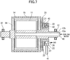
- a can roll 56 with a gas discharge mechanism includes a cylindrical member 10 that is rotationally driven about a center axis 56a by a drive apparatus not illustrated (see FIG. 9 ).
- a transfer path is defined along which to wrap and transfer a long heat-resistant resin film (long substrate) 52.
- a coolant circulation portion 11 (see FIGS. 4 and 7 ) with a jacket structure is formed through which a coolant such as cooling water flows.
- a rotary shaft 12 (see FIG. 9 ) situated at the position of the center axis 56a of the cylindrical member 10 has a double-pipe structure, and the coolant circulates between a coolant cooling apparatus not illustrated which is provided outside the vacuum chamber and the coolant circulation portion 11 through this rotary shaft 12. This makes it possible to adjust the temperature of the outer peripheral surface of the can roll 56.
- the coolant such as cooling water
- the coolant cooling apparatus is introduced from a cooling water inlet 40 and sent through an inner pipe 12a to the coolant circulation portion 11, at which the coolant receives the heat of the long substrate 52, thereby rising in temperature. Thereafter, the coolant is returned again to the coolant cooling apparatus through a space between the inner pipe 12a and an outer pipe 12b.
- bearings 32 that support the rotating can roll 56 are provided on the outer side of the outer pipe 12b.
- a plurality of gas introduction channels 14 are arranged over the entire circumference of the cylindrical member 10 of this can roll 56 at substantially equal intervals in the circumferential direction.
- the plurality of gas introduction channels 14 are each bored in a thick portion of the cylindrical member 10 so as to extend along the direction of the center axis 56a of the can roll 56.
- FIG. 9 illustrates an example where 12 gas introduction channels 14 are arranged over the entire circumference at equal intervals.
- Each gas introduction channel 14 includes a plurality of gas discharge holes 15 opening toward the outer surface of the cylindrical member 10 (i.e. the outer peripheral surface of the can roll 56).
- the plurality of gas discharge holes 15 are bored at substantially equal intervals along the direction of the center axis 56a of the can roll 56.
- a gas is supplied from outside the vacuum chamber into each gas introduction channel 14 through a rotary joint 20 including a rotary ring unit 21 and a fixed ring unit 22. In this way, the gas can be introduced into the gap regions (clearances) formed between the outer peripheral surface of the can roll 56 and the long substrate 52 wrapped thereon.
- the long substrate 52 and the surface of the can roll 56 are not completely flat surfaces. Then, with a vacuum therein, the gap regions (clearances) are thermally insulated by the vacuum and accordingly lower the thermal conductivity. This causes the formation of wrinkles on the long substrate 52 by the heat during the sputtering deposition.
- Non-Patent Document 2 in a case where the introduced gas is an argon gas and the pressure of the introduced gas is 500 Pa, then, when the gap regions (clearances) between the outer peripheral surface of a can roll and a film wrapped on the outer peripheral surface of the can roll are molecular flow regions measuring approximately 40 ⁇ m or shorter in distance, the thermal conductance of the gap regions is 250 (W/m 2 ⁇ K).
- the thermal conductance of the gap regions is 250 (W/m 2 ⁇ K).
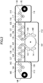
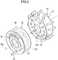
- the perpendicular rotary joint includes a rotary ring unit 21 and a fixed ring unit 22 fixed by a fixing member 41 so as not to rotate.
- the rotary ring unit 21 includes a plurality of gas supply channels 23 that communicate with the plurality of gas introduction channels 14 through connection pipes 25, respectively.
- each gas supply channel 23 includes a revolving opening portion 23a at the gas control sliding contact surface, the revolving opening portion 23a opening at an angular position corresponding to the angular position, on the outer peripheral surface of the can roll 56, of the gas introduction channel 14 communicating with the gas supply channel 23 through the corresponding connection pipe 25 (substantially the same angular position as the angular position on the outer peripheral surface of the can roll 56) .
- the fixed ring unit 22 includes a gas distribution channel 27 formed by an annular recessed groove 27a, including a fixed closed portion and a fixed opening portion, and communicating with a supply pipe 26 outside the vacuum chamber, the annular recessed groove 27a being provided in the gas control sliding contact surface so as to extend in the circumferential direction, the fixed closed portion being a portion at which the gas control sliding contact surface of the fixed ring unit 22 is closed by an arched packing member 42 fitted in a predetermined region inside the annular recessed groove 27a, the fixed opening portion being a portion at which the gas control sliding contact surface is not closed.
- the fixed opening portion opens within an angular range in the region on the gas control sliding contact surface of the fixed ring unit 22 which the revolving opening portions 23a of the rotary ring unit 21 face, the angular range being a range within which the long heat-resistant resin film (long substrate) 52 is wrapped.
- the structure is such that the revolving opening portions 23a of the rotary ring unit 21 face the fixed closed portion of the annular recessed groove 27a of the fixed ring unit 22, in which the arched packing member 42 is fitted, so that the gas supply channels 23 and the gas distribution channel 27 are disconnected from each other and the gas from outside the vacuum chamber is not supplied to the gas supply channels 23. Hence, the gas is not discharged from the gas discharge holes 15 in the outer peripheral surface of the can roll 56.
- the revolving opening portions 23a of the rotary ring unit 21 face the fixed opening portion of the annular recessed groove 27a of the fixed ring unit 22, in which the arched packing member 42 is not fitted, so that the gas supply channels 23 and the gas distribution channel 27 are connected to each other.
- the gas is discharged from the gas discharge holes 15 in the outer peripheral surface of the can roll 56, and the gas is introduced into the gap regions between the outer peripheral surface of the can roll 56 and the film 52.
- reference sign 43 in FIGS. 3 to 5 denote a packing attachment member
- reference sign 77 in FIG. 5 denotes a fixing screw hole in the rotary ring unit 21
- reference signs 82 and 83 in FIG. 5 denote a pressure gauge port for measuring the pressure in the gas distribution channel 27, which is equal to the gas pressure in the gaps between the outer peripheral surface of the can roll 56 and the long substrate 52 at the wrapped portion region of the surface of the can roll 56, at which the long substrate 52 is wrapped.
- the parallel rotary joint includes a rotary ring unit 21 which has a T-shaped cross section and includes a cylindrical base part 21a and a cylindrical protruding part 21b, and a fixed ring unit 22 in which the cylindrical protruding part 21b of the rotary ring unit 21 is fitted and which is fixed by a fixing member 41 so as not to rotate.
- each gas supply channel 23 includes a revolving opening portion 23a at the gas control sliding contact surface of the cylindrical protruding part 21b, the revolving opening portion 23a opening at an angular position corresponding to the angular position, on the outer peripheral surface of the can roll 56, of the gas introduction channel 14 communicating with the gas supply channel 23.
- the fixed ring unit 22 includes a gas distribution channel 27 formed by an annular recessed groove 27a, including a fixed closed portion and a fixed opening portion, and communicating with a supply pipe 26 outside the vacuum chamber, the annular recessed groove 27a being provided in the cylindrical inner peripheral surface of the fixed ring unit 22 so as to extend in the circumferential direction, the fixed closed portion being a portion at which the gas control sliding contact surface of the fixed ring unit 22 is closed by an arched packing member 42 fitted in a predetermined region inside the annular recessed groove 27a, the fixed opening portion being a portion at which the gas control sliding contact surface is not closed.
- the fixed opening portion opens within an angular range in the region on the gas control sliding contact surface of the fixed ring unit 22 which the revolving opening portions 23a of the cylindrical protruding part 21b of the rotary ring unit 21 face, the angular range being a range within which the long substrate 52 is wrapped.
- the structure is such that the revolving opening portions 23a of the rotary ring unit 21 face the fixed closed portion of the annular recessed groove 27a of the fixed ring unit 22, in which the arched packing member 42 is fitted, so that the gas supply channels 23 and the gas distribution channel 27 are disconnected from each other and the gas from outside the vacuum chamber is not supplied to the gas supply channels 23. Hence, the gas is not discharged from the gas discharge holes 15 in the outer peripheral surface of the can roll 56.
- the revolving opening portions 23a of the rotary ring unit 21 face the fixed opening portion of the annular recessed groove 27a of the fixed ring unit 22, in which the arched packing member 42 is not fitted, so that the gas supply channels 23 and the gas distribution channel 27 are connected to each other.
- the gas is discharged from the gas discharge holes 15 in the outer peripheral surface of the can roll 56, and the gas is introduced into the gap regions between the outer peripheral surface of the can roll 56 and the film 52.
- reference sign 43 in FIGS. 6 to 8 denote a packing attachment member
- reference sign 77 in FIG. 8 denotes a fixing screw hole in the rotary ring unit 21
- reference signs 82 and 83 in FIG. 8 denote a pressure gauge port for measuring the pressure in the gas distribution channel 27, which is equal to the gas pressure in the gaps between the outer peripheral surface of the can roll 56 and the long substrate 52 at the wrapped portion region of the surface of the can roll 56, at which the long substrate 52 is wrapped.
- the treatment apparatus according to the present invention has been described by taking a heat-resistant resin film as an example of the long substrate.
- resin films as a matter of course, and also metal films such as metal foils and metal strips are also usable as the long substrate used in the long substrate treatment apparatus according to the present invention.
- the resin films may include resin films with relatively poor heat resistance such as a polyethylene terephthalate (PET) film and heat-resistant resin films such as a polyimide film.
- a heat-resistant resin film selected from among a polyimide-based film, a polyamide-based film, a polyester-based film, a polytetrafluoroethylene-based film, a polyphenylene sulfide-based film, a polyethylene naphthalate-based film, and a liquid-crystal polymer-based film is preferably used.
- a metal film-coated heat-resistant resin film obtained using any of these is superior in flexibility required for metal film-coated flexible substrates, strength necessary to practical use, and electrical insulation performance preferable as a wiring material.
- a metal film-coated heat-resistant resin film can be manufactured by using the above heat-resistant resin film as the long substrate and performing sputtering deposition of metal films on the surface of the heat-resistant resin film.
- a metal film-coated heat-resistant resin film can be obtained which is the heat-resistant resin film with a film made of an Ni-based alloy or the like and a Cu film laminated on the surface of the heat-resistant resin film.
- the above metal film-coated heat-resistant resin film is sent to a further process, in which the metal film-coated heat-resistant resin film is processed by a subtractive method into a flexible wiring substrate including a predetermined wiring pattern.
- the subtractive method refers to a method of manufacturing a flexible wiring substrate by removing a metal film not covered by a resist (e.g. the above Cu film) by etching.
- the above film made of an Ni-based alloy or the like is called a seed layer, and its composition is selected as appropriate based on properties required for the metal film-coated heat-resistant resin film such as electric insulation performance and migration resistance. Generally, however, it is made of a publicly known alloy such as an Ni-Cr alloy, Inconel, constantan, or Monel. Note that a wet plating method is sometimes used in a case where a metal film (Cu film) of the metal film-coated heat-resistant resin film is desired to be thicker.
- used is a method in which the metal film is formed by only an electroplating process or a method in which a combination of wet plating processes such as an electroless plating process as primary plating and an electrolytic plating process as secondary plating.
- wet plating processes general wet plating conditions can be employed.
- a metal film-coated heat-resistant resin film obtained by laminating films of metals such as an Ni-Cr alloy and Cu on a long heat-resistant resin film.
- metals such as an Ni-Cr alloy and Cu
- the long substrate treatment apparatus has been described by taking a vacuum deposition apparatus as an example.
- the above treatment apparatus also covers treatments that apply a thermal load such as plasma treatment and ion beam treatment, besides vacuum deposition such as sputtering performed on a long substrate inside a vacuum chamber under a depressurized atmosphere. While these plasma treatment and ion beam treatment modify the surface of a long substrate, these apply a thermal load to the long substrate.
- the treatment apparatus according to the present invention is applicable to these cases and can prevent formation of wrinkles on the long substrate due to the thermal load without leaking a large amount of the introduced gas.
- the plasma treatment examples include a method in which a long substrate is processed with an oxygen plasma or nitrogen plasma generated via discharge through a mixed gas of argon and oxygen or a mixed gas of argon and nitrogen under a depressurized atmosphere.
- the ion beam treatment refers to a treatment in which a plasma discharge is generated in a magnetic field gap where a strong magnetic field is applied, and positive ions in the plasma as an ion beam to a long substrate.
- a publicly known ion beam source can be used in the ion beam treatment.
- these plasma treatment and ion beam treatment are both performed under a depressurized atmosphere.
- Examples 1 and 2 and reference examples 1 to 7 using the deposition apparatus (sputtering web coater) according to the present invention illustrated in FIG. 1 , and comparative examples 1 to 5 using the deposition apparatus (sputtering web coater) according to the conventional example illustrated in FIG. 10 are specifically described below.
- the diameter of the rotary joint (rotary ring unit 21 and fixed ring unit 22) was set to approximately 400 mm, and the number of connection pipes (gas introduction pipes) 25 on the rotary ring unit 21, connected to (communicating with) the gas introduction channels 14 of the can roll 56, was set to 36.
- gas control at angular intervals of 10° (360°/36 10°) was possible.
- the first infeed-side tension measurement roll 130 illustrated in FIG. 1 disposed near the infeed-side of the can roll 131, was set such that the can roll 131 and the long film 114 contacted each other at a 20° angle position.
- the first outfeed-side tension measurement roll 132 provided near the outfeed side of the can roll 131, was set such that the can roll 131 and the long film 114 contacted each other at a 340° angle position (in other words, the angle across the non-wrapped portion was set to 40°).
- the gas stop angle for the non-wrapped portion (the angle of the fixed closed portion formed by the arched packing member 42 fitted in a predetermined region inside the annular recessed groove 27a forming the gas distribution channel 27 of the fixed ring unit 22) was set to 90° (> 40° (the non-wrapped portion) + 20° ⁇ 2 (the unstable portions on both sides)).
- the arched packing member 42, disposed in the gas distribution channel 27, needs a function to close at most nine gas introduction channels 14, which corresponds to 90°.
- Long metal film-coated heat-resistant resin films were fabricated using the deposition apparatus (sputtering web coater) according to the present invention illustrated in FIG. 1 .
- the film 114 As the long heat-resistant resin film (hereinafter, referred to as the film 114), a heat-resistant polyimide film "UPILEX (registered trademark)", manufactured by Ube Industries, Ltd, measuring 500 mm in width, 800 m in length, and 25 ⁇ m in thickness was used.
- UPILEX registered trademark
- a can roll with a gas introduction mechanism having a jacket roll structure as illustrated in FIG. 9 was used.
- a stainless cylindrical member measuring 800 mm in diameter and 800 mm in width was used, and hard chromium plating was performed on its outer peripheral surface.
- 180 gas introduction channels 14 were bored over the entire circumference of a thick portion of this cylindrical member 10 at equal intervals in the circumferential direction, the gas introduction channels 14 measuring 5 mm in inner diameter and extending in parallel to the direction of the rotation axis of the can roll 131. Note that, of the two ends of each gas introduction channel 14, the distal end was formed into a closed bottom so as not to penetrate through the cylindrical member 10.
- Each gas introduction channel 14 was provided with 47 gas discharge holes 15 measuring 0.2 mm in inner diameter and opening toward the outer surface of the cylindrical member 10 (i.e. the outer peripheral surface of the can roll 131). These 47 gas discharge holes 15 were arranged at 10-mm intervals in a direction perpendicular to the direction of advance of the film 114 within a region between lines situated 20 mm inward from both sides of the transfer path of the film 114 defined on the outer surface of the cylindrical member 10. Specifically, the gas discharge holes 15 were not provided within 145-mm regions from both sides of the outer peripheral surface of the can roll 131.
- 180 gas introduction channels 14 were arranged over the entire circumference of the cylindrical member 10 at equal intervals in the circumferential direction. It is difficult to directly connect these 180 gas introduction channels 14 to the rotary joint 20. For this reason, sets of five gas introduction channels 14 were connected to branched pipes (not illustrated) and then connected to the ends of the connection pipes 25 on the rotary ring unit 21. Specifically, on the rotary ring unit 21 of the rotary joint 20, 36 connection pipes 25 were formed, as mentioned above, through each of which the gas was introduced collectively for 10°.
- a Cu film was formed on an Ni-Cr film, which was a seed layer.
- an Ni-Cr target was used as the magnetron sputter target 139
- Cu targets were used as the magnetron sputter targets 140, 141, and 142.
- the film 114 in a rolled up state was set on the unwinding roll 115 of the above deposition apparatus (sputtering web coater), and one end of the film 114 was attached to the winding roll 146 through the can roll 131.
- the air in the vacuum chamber in the deposition chamber 112 was evacuated to 5 Pa by using a plurality of dry pumps and evacuated further to 3 ⁇ 10 -3 Pa by using a plurality of turbomolecular pumps and cryocoils.
- a rotational drive apparatus was actuated to transfer the long film 114 at a transfer speed of 8 m/min while an argon gas was introduced at 300 sccm and also electric power control was performed to apply an electric power of 20 kW to the magnetron sputter cathodes 139, 140, 141, and 142. Further, with a diaphragm gauge attached to the pressure gauge port 82, 83 (see FIG.
- the flow rate of the argon gas from the supply pipe 26 of the fixed ring unit 22 was controlled such that the set gas pressure in the gaps between the surface of the can roll and the film could be at the value (450 to 1350 Pa) listed in table 1-3 below.
- a treatment of continuously forming a seed layer made of an Ni-Cr film and a Cu film to be formed on the seed layer was started under the above conditions on one surface of the film 114 transferred in a roll-to-roll manner.
- Tables 1-1 to 1-3 below list the "Unwinding Tension” (measured by the tension measurement roll 117 illustrated in FIG. 1 ), the “Drying Tension” (measured by the tension measurement roll 121), the “Infeed Tension Tu2" (measured by the second infeed-side tension measurement roll 127), the “Infeed Tension Tu1” (measured by the first infeed-side tension measurement roll 130), the “Outfeed Tension Td1"(measured by the first outfeed-side tension measurement roll 132), the “Outfeed Tension Td2"(measured by the second outfeed-side tension measurement roll 135), and the “Winding Tension” (measured by the tension measurement roll 144) in examples 1 and 2 and reference examples 1 to 7.
- the "Infeed Tension Tu2" and the “Outfeed Tension Td2" in reference examples 1 and 2 are set to be equal to the adjacent "Infeed Tension Tu1" and "Outfeed Tension Td1", respectively, the "Infeed Tension Tu2" in reference examples 3 and 4 is set to be equal to the adjacent "Drying Tension”, and the "Outfeed Tension Td2" in reference examples 3 to 5 is also set to be equal to the adjacent "Winding Tension".
- reaction Pa the force with which the long film 114 is pressed against the can roll 131
- set Gas Pressure Pa in Gaps (equal to 90% of the reaction Pa) in examples 1 and 2 and reference examples 1 to 7, which are determined depending on the setting of the "Infeed Tension Tu1" and the “Outfeed Tension Td1", are listed as well.
- Long metal film-coated heat-resistant resin films were fabricated using the deposition apparatus (sputtering web coater) accordingly to the conventional example illustrated in FIG. 10 .
- the film 214 the heat-resistant polyimide film "UPILEX (registered trademark)", manufactured by Ube Industries, Ltd, measuring 500 mm in width, 800 m in length, and 25 ⁇ m in thickness was used.
- UPILEX registered trademark
- a can roll with a gas introduction mechanism having a jacket roll structure as illustrated in FIG. 9 was used.
- the cylindrical member 10 (see FIG. 9 ) of this can roll 231 a stainless cylindrical member measuring 800 mm in diameter and 800 mm in width was used, and hard chromium plating was performed on its outer peripheral surface.
- 180 gas introduction channels 14 were bored over the entire circumference of a thick portion of this cylindrical member 10 at equal intervals in the circumferential direction, the gas introduction channels 14 measuring 5 mm in inner diameter and extending in parallel to the direction of the rotation axis of the can roll 231. Note that, of the two ends of each gas introduction channel 14, the distal end was formed into a closed bottom so as not to penetrate through the cylindrical member 10.
- Each gas introduction channel 14 was provided with 47 gas discharge holes 15 (see FIG. 9 ) measuring 0.2 mm in inner diameter and opening toward the outer surface of the cylindrical member 10 (i.e. the outer peripheral surface of the can roll 231). These 47 gas discharge holes 15 were arranged at 10-mm intervals in a direction perpendicular to the direction of advance of the film 214 within a region between lines situated 20 mm inward from both sides of the transfer path of the film 214 defined on the outer surface of the cylindrical member 10. Specifically, the gas discharge holes 15 were not provided within 145-mm regions from both sides of the outer peripheral surface of the can roll 231.
- 180 gas introduction channels 14 were arranged over the entire circumference of the cylindrical member 10 at equal intervals in the circumferential direction. It is difficult to directly connect these 180 gas introduction channels 14 to the rotary joint 20 (see FIG. 9 ). For this reason, sets of five gas introduction channels 14 were connected to branched pipes (not illustrated) and then connected to the ends of the connection pipes 25 on the rotary ring unit 21. Specifically, on the rotary ring unit 21 of the rotary joint 20, 36 connection pipes 25 were formed, as mentioned above, through each of which the gas was introduced collectively for 10°.
- a Cu film was formed on an Ni-Cr film, which was a seed layer.
- an Ni-Cr target was used as the magnetron sputter target 239
- Cu targets were used as the magnetron sputter targets 240, 241, and 242.
- the film 214 in a rolled up state was set on the unwinding roll 215 of the above deposition apparatus (sputtering web coater), and one end of the film 214 was attached to the winding roll 246 through the can roll 231.
- the air in the vacuum chamber in the deposition chamber 212 was evacuated to 5 Pa by using a plurality of dry pumps and evacuated further to 3 ⁇ 10 -3 Pa by using a plurality of turbomolecular pumps and cryocoils.
- a rotational drive apparatus was actuated to transfer the long film 214 at a transfer speed of 8 m/min while an argon gas was introduced at 300 sccm and also electric power control was performed to apply an electric power of 20 kW to the magnetron sputter cathodes 239, 240, 241, and 242.
- the flow rate of the argon gas from the supply pipe 26 of the fixed ring unit 22 was controlled such that the set gas pressure in the gaps between the surface of the can roll and the film could be at the value (450 to 1125 Pa) listed in table 1-3 below.
- a treatment of continuously forming a seed layer made of an Ni-Cr film and a Cu film to be formed on the seed layer was started under the above conditions on one surface of the film 214 transferred in a roll-to-roll manner.
- tables 1-1 to 1-3 below list the "Unwinding Tension” (measured by the tension measurement roll 217 illustrated in FIG. 10 ), the “Drying Tension” (measured by the tension measurement roll 221), the “Infeed Tension Tu1” (measured by the infeed-side tension measurement roll 230), the “Outfeed Tension Td1"(measured by the outfeed-side tension measurement roll 232), and the “Winding Tension” (measured by the tension measurement roll 244) in comparative examples 1 to 5.
- reaction Pa the force with which the long film 214 is pressed against the can roll 231
- set Gas Pressure Pa in Gaps (equal to 90% of the reaction Pa) in comparative examples 1 to 5, which are determined depending on the setting of the "Infeed Tension Tu1" and the "Outfeed Tension Td1", are listed as well.
- Table 1-1 Example Name Tension Zone Unwinding Tension Drying Tension Unit N N Tension Measurement Roll No.
- the long substrate treatment apparatus and treatment method according to the present invention can avoid formation of film wrinkles and scratches.
- the long substrate treatment apparatus and treatment method according to the present invention therefore have a possibility of industrial application that they are employed as a manufacturing apparatus and manufacturing method for copper-laminated resin films (metal film-coated heat-resistant resin films) for use as flexible wiring substrates in liquid crystal televisions, mobile phones, and so on.
- An apparatus that performs sputtering or the like on a long film 114 supplied from an unwinding chamber 110 and wrapped on a can roll 131 with a gas discharge mechanism in a deposition chamber 112 is characterized in that the apparatus includes a pair of tension control roll groups (a first tension measurement roll 130 and first motor driven roll 129, and a second tension measurement roll 127 and second motor driven roll 125) on the film infeed side of the can roll, and also a pair of tension control roll groups (a first tension measurement roll 132 and first motor driven roll 133, and a second tension measurement roll 135 and second motor driven roll 137) on the outfeed side of the can roll.
- Two-stage control of the infeed feed tension and the outfeed feed tension of the can roll is performed using the two pairs of tension control roll groups, respectively. This allows accurate control on the tension of the film and thus makes it possible to avoid formation of scratches or the like.
Landscapes
- Chemical & Material Sciences (AREA)
- Engineering & Computer Science (AREA)
- Chemical Kinetics & Catalysis (AREA)
- Materials Engineering (AREA)
- Mechanical Engineering (AREA)
- Metallurgy (AREA)
- Organic Chemistry (AREA)
- Physics & Mathematics (AREA)
- Plasma & Fusion (AREA)
- Analytical Chemistry (AREA)
- Physical Vapour Deposition (AREA)
- Controlling Rewinding, Feeding, Winding, Or Abnormalities Of Webs (AREA)
Abstract
Description
- The present invention relates to a long substrate treatment apparatus and treatment method for performing a treatment that applies a thermal load such as ion beam treatment or sputtering deposition on a long substrate such as a heat-resistant resin film transferred through a vacuum chamber in a roll-to-roll manner and wrapped on the outer peripheral surface of a can roll with a gas discharge mechanism, and relates in particular to a long substrate treatment apparatus and treatment method by which a long substrate is less prone to formation of wrinkles, scratches, and the like.
- Flexible wiring substrates are used in liquid crystal panels, laptop computers, digital cameras, mobile phones, and so on. A flexible wiring substrate is fabricated from a metal film-coated heat-resistant resin film obtained by forming a metal film on one or both surfaces of heat-resistant resin film. In recent years, wiring patterns formed on flexible wiring substrates have increasingly become finer and denser and it has become more important for metal film-coated heat-resistant resin films themselves to be flat and smooth with no wrinkles or the like.
- Conventional methods of manufacturing this type of metal film-coated heat-resistant resin film have known such as: a manufacturing method in which a metal foil is attached to a heat-resistant resin film with an adhesive (referred to as the three-layer substrate manufacturing method); a manufacturing method in which a metal foil is coated with a heat-resistant resin solution and then the resin solution is dried (referred to as the casting method); and a manufacturing method in which a metal film is formed on a heat-resistant resin film by a dry plating method (vacuum deposition method) or a combination of a dry plating method (vacuum deposition method) and a wet plating method (referred to as the metallizing method). Also, the dry plating method (vacuum deposition method) in the metallizing method includes vacuum vapor deposition methods, sputtering methods, ion plating methods, ion beam sputtering methods, and so on.
- As the metallizing method,
Patent Document 1 discloses a method in which chromium is sputtered onto a polyimide insulating layer and then copper is sputtered to form a conductive layer on the polyimide insulating layer. Also, Patent Document 2 discloses a flexible circuit board material formed by sequentially laminating a first metal thin film formed by sputtering a target of a copper-nickel alloy and a second metal thin film formed by sputtering a target of copper onto a polyimide film. Note that a sputtering web coater is usually used to perform vacuum deposition on a heat-resistant resin film (substrate) such as a polyimide film. - Generally, among the vacuum deposition methods mentioned above, the sputtering methods have been said to provide better bond but apply a larger thermal load to the heat-resistant resin film than the vacuum vapor deposition methods. Moreover, it has also been known that applying a large thermal load to the heat-resistant resin film during the deposition makes the film more prone to formation of wrinkles. To prevent the formation of the wrinkles, sputtering web coaters as apparatuses for manufacturing a metal film-coated heat-resistant resin film are equipped with a can roll having a cooling function, and employ an method in which this can roll is rotationally driven while a heat-resistant resin film transferred in a roll-to-roll manner is wrapped on a transfer path defined on the outer peripheral surface of the can roll, to thereby cool the heat-resistant resin film from its back surface during the sputtering process.
- For example,
Patent Document 3 discloses an unwinding-winding type (roll-to-roll type) vacuum sputtering apparatus as an example of the sputtering web coaters. This unwinding-winding type vacuum sputtering apparatus includes a cooling roll that serves as the above can roll, and performs control that brings a film into tight contact with the cooling roll by using an additional sub roll provided at least on the film infeed side or the film outfeed side of the cooling roll. - However, as described in Non-Patent
Document 1, the outer peripheral surface of the can roll is not flat when viewed microscopically. Thus, between the can roll and the film transferred in tight contact with its outer peripheral surface, gap regions (clearances) are present which separate them with a vacuum space therebetween. Accordingly, it cannot be said that the heat in the film generated during sputtering or vapor deposition is actually efficiently transferred to the can roll from the film. This has been a cause of the formation of film wrinkles. - To solve this, a technique has been proposed in which a gas is introduced into the gap regions between the outer peripheral surface of the can roll and the film from the can roll side to thereby make the thermal conductivity of the gap regions higher than the vacuum.
- Further, as specific methods of introducing a gas into the gap regions from the can roll side, for example Patent Document 4 discloses a technique in which many small holes are provided in the outer peripheral surface of a can roll as gas discharge ports, and Patent Document 5 discloses a technique in which grooves are provided in the outer peripheral surface of a can roll as gas discharge ports. Moreover, a method in which a can roll itself is made from a porous body and the small holes in the porous body itself are used as gas discharge ports.
- Meanwhile, in methods in which small holes, grooves, or the like are provided in the outer peripheral surface of a can roll as gas discharge ports, the resistance at the gas discharge ports are lower in the region of the outer peripheral surface of the can roll where the film is not wrapped (non-wrapped portion region) than in the region where the film is wrapped (wrapped portion region). This sometimes leads to a situation where the gas supplied to the can roll is mostly discharged to the space in the vacuum chamber from the gas discharge ports in the non-wrapped portion region, which results in a failure to supply the amount of gas that is supposed to be introduced into the gap regions between the outer peripheral surface of the can roll and the film wrapped thereon, and thus makes it impossible to achieve the thermal conductivity enhancing effect mentioned above.
- To solve this problem, methods have been proposed such as: a method in which valves that project from the outer peripheral surface of a can roll are provided in gas discharge ports, and the gas discharge ports are opened by pressing a film surface against the respective valves (Patent Document 5); and a method in which a cover is attached to the region of the outer peripheral surface of a can roll where a film is not wrapped (the non-wrapped portion region of the outer peripheral surface of the can roll) to thereby prevent discharge of a gas from the non-wrapped portion region to the space in the vacuum chamber and thus efficiently introduce the gas into the gap regions between the outer peripheral surface of the can roll and the film surface (see Patent Document 6).
- However, with the method of Patent Document 5, in which the gas discharge ports are opened by pressing the film surface against the respective valves projecting from the outer peripheral surface of the can roll, there is a possibility that the film surface is slightly damaged or dented by its contact with the valves. Thus, it is difficult to employ the method of Patent Document 5 for manufacturing flexible wiring substrates for electronic devices that are required to have high quality. Also, with the method of Patent Document 6, in which a cover is attached to the region of the outer peripheral surface of a can roll where a film is not wrapped (non-wrapped portion region), gas is likely to leak from the clearance between the cover and the outer peripheral surface of the can roll in a treatment apparatus that performs deposition under high vacuum. Thus, like the method of Patent Document 5, it is difficult to employ the method of Patent Document 6.
- Under these technical circumstances, the present inventor has already proposed a can roll with a structure that does not supply a gas to the outer peripheral surface of the can roll at the region where the film is not wrapped (non-wrapped portion region) to thereby prevent discharge of the gas from the non-wrapped portion region (see Patent Document 7). Specifically, as illustrated in
FIG. 9 , this can roll is a canroll 56 provided with a plurality ofgas introduction channels 14 in a thick portion of the can roll 56, manygas discharge holes 15 are provided in eachgas introduction channel 14, and the can roll 56 is controlled so as to supply a gas from outside the vacuum chamber selectively to thegas introduction channels 14 through arotary joint 20 including afixed ring unit 22 and arotary ring unit 21. - Meanwhile, in Non-Patent Document 2, it is reported that, in a case where the introduced gas is an argon gas and the pressure of the introduced gas is 500 Pa, then, when the gap regions (clearances) between the outer peripheral surface of a can roll and a film wrapped on the outer peripheral surface of the can roll are molecular flow regions measuring approximately 40 µm or shorter in distance, the thermal conductance of the gap regions is 250 (W/m2·K) (see page 752 of Non-Patent Document 2).
- Further, for a long substrate treatment apparatus employing the can roll 56 with a gas discharge mechanism in
Patent Document 7 too, the higher the gas pressure in the gap regions between the outer peripheral surface of the can roll and a film (long substrate) 52 at the wrapped portion region, the higher the thermal conductance (the efficiency of heat transfer by molecular flows) and therefore the higher the efficiency of the cooling of thelong substrate 52. - However, if the gas pressure in the gap regions is higher than a reaction P = T/R (R: the radius of the can roll) which is a force with which the
long substrate 52 is pressed against the can roll 56 under a tension T in the direction of transfer of thelong substrate 52, thelong substrate 52 floats from the outer peripheral surface of the can roll 56, which makes it difficult to control the gas pressure. It is therefore important to control the gas pressure in the gap regions between the outer peripheral surface of the can roll 56 and thelong substrate 52, and also important to control the tension of thelong substrate 52 during its transfer simultaneously with the gas pressure control. - Thus, in the long substrate treatment apparatus employing the can roll with a gas discharge mechanism, the pressure of the gas to be introduced into the gap regions is controlled to be slightly lower than the reaction P (the force with which the
long substrate 52 is pressed against the can roll 56) so as to satisfy conditions for the gas pressure and the tension. This brings the gas pressure and the reaction P into equilibrium and thus makes the friction force (grip force) between the can roll 56 and thelong substrate 52 extremely low. Then, without accurately controlling the tensions of thelong substrate 52 transferred upstream and downstream of the can roll 56, thelong substrate 52 may possibly slip on the surface of the can roll 56 and scratches may possibly be formed on thelong substrate 52. -
- Patent Document 1: Japanese Patent Application Publication No.
Hei 2-98994 - Patent Document 2: Japanese Patent No.
3447070 - Patent Document 3: Japanese Patent Application Publication No.
Sho 62-247073 - Patent Document 4: Pamphlet of International Publication No.
WO2005/001157 - Patent Document 5: Specification of
U.S. Patent No. 3414048 - Patent Document 6: Pamphlet of International Publication No.
2002/070778 - Patent Document 7: Japanese Patent Application Publication No.
2012-132081 -
- Non-Patent Document 1: "Vacuum Heat Transfer Models for Web Substrates: Review of Theory and Experimental Heat Transfer Data", 2000 Society of Vacuum Coaters, 43rd Annual Technical Conference Proceeding, Denver, April 15-20, 2000, p.335
- Non-Patent Document 2: "Improvement of Web Condition by the Deposition Drum Design", 2000 Society of Vacuum Coaters, 50th Annual Technical Conference Proceeding (2007), p.749
- However, contrary to the above demand for long substrate tension control, large-scale sputtering web coaters (long substrate treatment apparatuses) have difficulty in accurately controlling the tensions of a long substrate transferred upstream and downstream of a can roll. This is because, as illustrated in
FIG. 10 , large-scale sputtering web coaters include anunwinding chamber 210 that includes anunwinding roll 215 therein and unwinds a heat-resistant resin film (long substrate) 214 before deposition, adrying chamber 211 that dries thelong substrate 214 before the deposition, adeposition chamber 212 that includes thereinmagnetron sputtering cathodes long substrate 214 transferred from thedrying chamber 211, awinding chamber 213 that includes awinding roll 246 therein and winds thelong substrate 214 after the deposition transferred from thedeposition chamber 212, and so on, and the tension of thelong substrate 214 transferred through these zones is set differently from one zone to another. - For example, the unwinding tension of the
long substrate 214 in theunwinding chamber 210, illustrated inFIG. 10 , (a tension based on the difference in circumferential speed between theunwinding roll 215 and a motor drivenroll 219 in the drying chamber 211) is measured by atension measurement roll 217 in theunwinding chamber 210, and the measurement data is fed back to theunwinding roll 215 to control the circumferential speed of theunwinding roll 215. - The drying tension of the
long substrate 214 in the drying chamber 211 (a tension based on the difference in circumferential speed between the motor drivenroll 219 and an infeed-side motor drivenroll 229 in the deposition chamber 212) is measured by atension measurement roll 221 in thedrying chamber 211, and the measurement data is fed back to the motor drivenroll 219 to control the circumferential speed of the motor drivenroll 219. - Also, an infeed tension Tu1 of the
long substrate 214 in the deposition chamber 212 (a tension based on the difference in circumferential speed between the infeed-side motor drivenroll 229 and the can roll 231) is measured by an infeed-sidetension measurement roll 230 in thedeposition chamber 212, and the measurement data is fed back to the infeed-side motor drivenroll 229 to control the circumferential speed of the infeed-side motor drivenroll 229. Moreover, an outfeed tension Td1 of thelong substrate 214 in the deposition chamber 212 (a tension based on the difference in circumferential speed between the can roll 231 and an outfeed-side motor drivenroll 233 in the deposition chamber 212) is measured by an outfeed-sidetension measurement roll 232 in thedeposition chamber 212, and the measurement data is fed back to the outfeed-side motor drivenroll 233 to control the circumferential speed of the outfeed-side motor drivenroll 233. - Further, the winding tension of the
long substrate 214 in the winding chamber 213 (a tension based on the difference in circumferential speed between the outfeed-side motor drivenroll 233 in thedeposition chamber 212 and thewinding roll 246 in the winding chamber 213) is measured by atension measurement roll 244 in thewinding chamber 213, and the measurement data is fed back to thewinding roll 246 to control the circumferential speed of thewinding roll 246. - Here, in
FIG. 10 , the motor driven rolls (including theunwinding roll 215, the can roll 231, and the winding roll 246) are denoted by reference sign M (motor), the tension measurement rolls are denoted by reference sign TP (tension pick up), and the free rolls are denoted by reference sign F (free) (the same applies toFIGS. 1 and2 ). Also, inFIG. 10 , thelong substrate 214 unwound from the unwindingroll 215 is illustrated using two ways of unwinding with a solid line and a chain line, and thelong substrate 214 wound around the windingroll 246 is also illustrated using two ways with a solid line and a chain line. - Further, the tension of the
long substrate 214 transferred through the zones of the unwindingchamber 210, the dryingchamber 211, thedeposition chamber 212, and the windingchamber 213 is set differently from one zone to another. There are cases where, for example, the drying tension of thelong substrate 214 transferred through the dryingchamber 211 is set to 30 N (newton) and the infeed tension and outfeed tension of thelong substrate 214 transferred through thedeposition chamber 212 are set to 200 N. This large tension difference is controlled by the motor driven rolls, the motor driven can roll, and so on. However, with the large tension difference, the problem is that it is difficult to control that tension difference with the motor driven rolls, the can roll, and so on, which causes slippage, vibration, or the like of thelong substrate 214 on the surface of the can roll 231, thereby making the tension unstable and forming scratches or the like on thelong substrate 214. - In the sputtering web coater (long substrate treatment apparatus) illustrated in
FIG. 10 , the zones of the unwindingchamber 210, the dryingchamber 211, thedeposition chamber 212, and the windingchamber 213 are provided in respective individual chambers. Note that the above problem occurs similarly with long substrate treatment apparatuses in which an unwinding zone, a drying zone, a deposition zone, and a winding zone are provided in a single chamber. - The present invention has been made in view of such a problem and an object thereof is to provide a long substrate treatment apparatus and treatment method by which a long substrate is less prone to formation of wrinkles, scratches, and the like by performing two-stage control on the tension of the long substrate infed toward a can roll with a gas discharge mechanism in the direction of the infeed (infeed tension) and on the tension of the long substrate outfeed from the can roll in the direction of the outfeed (outfeed tension) with two pairs of tension control roll groups provided on the infeed side and the outfeed side of the can roll, respectively.
- That is, a first aspect according to the present invention is a long substrate treatment apparatus which includes:
- an unwinding zone in which to unwind a long substrate wound around an unwinding roll;
- a treatment zone in which to perform a treatment that applies a thermal load in a vacuum chamber on the long substrate fed from the unwinding zone; and
- a winding zone in which to wind the long substrate subjected to the treatment,
- the treatment zone including
- a motor driven can roll that cools the long substrate transferred in a roll-to-roll manner and wrapped on an outer peripheral surface of the can roll,
- an infeed-side tension control roll group and an outfeed-side tension control roll group provided on an infeed side and an outfeed side of the can roll where the long substrate is infed toward and outfed from the can roll, respectively, and
- thermal load applying treatment means positioned so as to face the outer peripheral surface of the can roll,
- a plurality of gas introduction channels being arranged over an entire circumference of the can roll at substantially equal intervals in a circumferential direction, the plurality of gas introduction channels each including a plurality of gas discharge holes opening toward the outer peripheral surface at substantially equal intervals along a direction of a rotary shaft of the can roll, and
- the long substrate treatment apparatus including a rotary joint that supplies a gas from outside the vacuum chamber to the gas introduction channels situated within an angular range of the outer peripheral surface of the can roll within which the long substrate is wrapped, and does not supply the gas from outside the vacuum chamber to the gas introduction channels not situated within the angular range within which the long substrate is wrapped,
- characterized in that
- the infeed-side tension control roll group includes a first infeed-side tension control roll group and a second infeed-side tension control roll group each provided in the treatment zone, the first infeed-side tension control roll group including a first infeed-side tension measurement roll disposed near the infeed side of the can roll and a first infeed-side motor driven roll whose circumferential speed is controlled based on a tension of the long substrate measured by the first infeed-side tension measurement roll, the second infeed-side tension control roll group including a second infeed-side tension measurement roll disposed on the first infeed-side motor driven roll side and a second infeed-side motor driven roll whose circumferential speed is controlled based on a tension of the long substrate measured by the second infeed-side tension measurement roll,
- the outfeed-side tension control roll group includes a first outfeed-side tension control roll group and a second outfeed-side tension control roll group each provided in the treatment zone, the first outfeed-side tension control roll group including a first outfeed-side tension measurement roll disposed near the outfeed side of the can roll and a first outfeed-side motor driven roll whose circumferential speed is controlled based on a tension of the long substrate measured by the first outfeed-side tension measurement roll, the second outfeed-side tension control roll group including a second outfeed-side tension measurement roll disposed on the first outfeed-side motor driven roll side and a second outfeed-side motor driven roll whose circumferential speed is controlled based on a tension of the long substrate measured by the second outfeed-side tension measurement roll,
- a tension of the long substrate infed toward the can roll in the direction of the infeed is adjusted by two-stage control using an infeed tension (Tu1) set based on a difference in circumferential speed between the can roll and the first infeed-side motor driven roll and an infeed tension (Tu2) (Tu1 > Tu2) set based on a difference in circumferential speed between the first infeed-side motor driven roll and the second infeed-side motor driven roll, and
- a tension of the long substrate outfed from the can roll in the direction of the outfeed is adjusted by two-stage control using an outfeed tension (Td1) set based on a difference in circumferential speed between the first outfeed-side motor driven roll and the can roll, and an outfeed tension (Td2) (Td1 > Td2) set based on a difference in circumferential speed between the second outfeed-side motor driven roll and the first outfeed-side motor driven roll.
- Also, a second aspect of the present invention is the long substrate treatment apparatus according to the first aspect, characterized in that
the rotary joint includes a rotary ring unit and a fixed ring unit provided coaxially with the can roll and each including a gas control sliding contact surface formed perpendicularly to a center axis of the can roll,
the rotary ring unit includes a plurality of gas supply channels communicating with the plurality of gas introduction channels in the can roll, respectively, the plurality of gas supply channels each including a revolving opening portion at the gas control sliding contact surface of the rotary ring unit, the revolving opening portion opening at an angular position corresponding to an angular position, on the outer peripheral surface of the can roll, of the gas introduction channel communicating with the gas supply channel,
the fixed ring unit includes a gas distribution channel formed by an annular recessed groove, including a fixed closed portion and a fixed opening portion, and communicating with a supply pipe outside the vacuum chamber, the annular recessed groove being provided in the gas control sliding contact surface of the fixed ring unit so as to extend in the circumferential direction, the fixed closed portion being a portion at which the gas control sliding contact surface of the fixed ring unit is closed by an arched packing member fitted in a predetermined region inside the annular recessed groove, the fixed opening portion being a portion at which the gas control sliding contact surface is not closed, and
the fixed opening portion opens within an angular range in a region on the gas control sliding contact surface of the fixed ring unit which the revolving opening portions of the rotary ring unit face, the angular range being a range within which the long substrate is wrapped. - A third aspect is the long substrate treatment apparatus according to the first aspect, characterized in that
the rotary joint includes a rotary ring unit having a T-shaped cross section and including a cylindrical base part and a cylindrical protruding part provided coaxially with the can roll, and a cylindrical fixed ring unit in which the cylindrical protruding part of the rotary ring unit is fitted such that the cylindrical protruding part of the rotary ring unit and the fixed ring unit each include a gas control sliding contact surface in parallel to a center axis of the can roll,
the rotary ring unit includes a plurality of gas supply channels communicating with the plurality of gas introduction channels in the can roll, respectively, the plurality of gas supply channels each including a revolving opening portion at the gas control sliding contact surface of the cylindrical protruding part of the rotary ring unit, the revolving opening portion opening at an angular position corresponding to an angular position, on the outer peripheral surface of the can roll, of the gas introduction channel communicating with the gas supply channel,
the fixed ring unit includes a gas distribution channel formed by an annular recessed groove, including a fixed closed portion and a fixed opening portion, and communicating with a supply pipe outside the vacuum chamber, the annular recessed groove being provided in a cylindrical inner circumferential surface of the fixed ring unit so as to extend in the circumferential direction, the fixed closed portion being a portion at which the gas control sliding contact surface of the fixed ring unit is closed by an arched packing member fitted in a predetermined region inside the annular recessed groove, the fixed opening portion being a portion at which the gas control sliding contact surface is not closed, and
the fixed opening portion opens within an angular range in a region on the gas control sliding contact surface of the fixed ring unit which the revolving opening portions of the cylindrical protruding part of the rotary ring unit face, the angular range being a range within which the long substrate is wrapped. - Further, a fourth aspect according to the present invention is the long substrate treatment apparatus according to any one of the first to third aspects, characterized in that the treatment that applies a thermal load is a treatment with vacuum deposition means facing a transfer path defined on the outer peripheral surface of the can roll.
- A fifth aspect is the long substrate treatment apparatus according to the fourth aspect, characterized in that the vacuum deposition means includes a magnetron sputtering cathode.
- Also, a sixth aspect according to the present invention is a long substrate treatment method which uses
an unwinding zone in which to unwind a long substrate wound around an unwinding roll,
a treatment zone in which to perform a treatment that applies a thermal load in a vacuum chamber on the long substrate fed from the unwinding zone, and
a winding zone in which to wind the long substrate subjected to the treatment,
the long substrate treatment method including forming the treatment zone from - a motor driven can roll that cools the long substrate transferred in a roll-to-roll manner and wrapped on an outer peripheral surface of the can roll,
- an infeed-side tension control roll group and an outfeed-side tension control roll group provided on an infeed side and an outfeed side of the can roll where the long substrate is infed toward and outfed from the can roll, respectively, and
- thermal load applying treatment means positioned so as to face the outer peripheral surface of the can roll,
- forming the infeed-side tension control roll group from a first infeed-side tension control roll group and a second infeed-side tension control roll group each provided in the treatment zone, the first infeed-side tension control roll group including a first infeed-side tension measurement roll disposed near the infeed side of the can roll and a first infeed-side motor driven roll whose circumferential speed is controlled based on a tension of the long substrate measured by the first infeed-side tension measurement roll, the second infeed-side tension control roll group including a second infeed-side tension measurement roll disposed on the first infeed-side motor driven roll side and a second infeed-side motor driven roll whose circumferential speed is controlled based on a tension of the long substrate measured by the second infeed-side tension measurement roll;
- forming the outfeed-side tension control roll group from a first outfeed-side tension control roll group and a second outfeed-side tension control roll group each provided in the treatment zone, the first outfeed-side tension control roll group including a first outfeed-side tension measurement roll disposed near the outfeed side of the can roll and a first outfeed-side motor driven roll whose circumferential speed is controlled based on a tension of the long substrate measured by the first outfeed-side tension measurement roll, the second outfeed-side tension control roll group including a second outfeed-side tension measurement roll disposed on the first outfeed-side motor driven roll side and a second outfeed-side motor driven roll whose circumferential speed is controlled based on a tension of the long substrate measured by the second outfeed-side tension measurement roll;
- adjusting a tension of the long substrate infed toward the can roll in the direction of the infeed by two-stage control using an infeed tension (Tu1) set based on a difference in circumferential speed between the can roll and the first infeed-side motor driven roll and an infeed tension (Tu2) (Tu1 > Tu2) set based on a difference in circumferential speed between the first infeed-side motor driven roll and the second infeed-side motor driven roll; and
- adjusting a tension of the long substrate outfed from the can roll in the direction of the outfeed by two-stage control using an outfeed tension (Td1) set based on a difference in circumferential speed between the first outfeed-side motor driven roll and the can roll, and an outfeed tension (Td2) (Td1 > Td2) set based on a difference in circumferential speed between the second outfeed-side motor driven roll and the first outfeed-side motor driven roll.
- The long substrate treatment apparatus and treatment method according to the present invention are characterized in that
the tension of the long substrate infed toward the can roll in the direction of the infeed is adjusted by two-stage control using the infeed tension Tu1, which is set based on the difference in circumferential speed between the can roll and the first infeed-side motor driven roll, and the infeed tension Tu2 (Tu1 > Tu2), which is set based on the difference in circumferential speed between the first infeed-side motor driven roll and the second infeed-side motor driven roll, and
the tension of the long substrate outfed from the can roll in the direction of the outfeed is adjusted by two-stage control using the outfeed tension Td1, which is set based on the difference in circumferential speed between the first outfeed-side motor driven roll and the can roll, and the outfeed tension (Td2) (Td1 > Td2), which is set based on the difference in circumferential speed between the second outfeed-side motor driven roll and the first outfeed-side motor driven roll. - Then, even in the case where a large difference is set between the tension of the long substrate transferred through the treatment zone, in which a thermal load is applied, and the tension of the long substrate transferred through a zone adjacent to the treatment zone, such as the drying zone or the winding zone, such a case can be handled by the two-stage control on the infeed tension and the outfeed tension in the treatment zone. It is therefore possible to solve the problem of formation of scratches or the like on the long substrate due to slippage of the long substrate on the surface of the can roll.
- Further, the two-stage control on the infeed tension and the outfeed tension in the treatment zone makes it possible to set the gas pressure in the gap regions between the outer peripheral surface of the can roll and the long substrate at the wrapped portion region to an appropriate condition. This improves the thermal conductance (heat transfer efficiency) and makes it possible to solve the problem of formation of wrinkles or the like on the long substrate.
-
-
FIG. 1 is an explanatory diagram illustrating a schematic configuration of a long substrate treatment apparatus according a first embodiment of the present invention including an unwinding chamber, a drying chamber, a deposition chamber, and a winding chamber and further including a can roll with a gas discharge mechanism disposed in the deposition chamber, where sign "Tu1" denotes an infeed tension Tu1, sign "Tu2" denotes an infeed tension Tu2, sign "Td1" denotes an outfeed tension Td1, and sign "Td2" denotes an outfeed tension Td2. -
FIG. 2 is an explanatory diagram illustrating a schematic configuration of a long substrate treatment apparatus according a second embodiment of the present invention including an unwinding chamber, a deposition chamber, and a winding chamber and further including a can roll with a gas discharge mechanism disposed in the deposition chamber. -
FIG. 3 is a schematic perspective view of a fixed ring unit and a rotary ring unit each including a gas control sliding contact surface formed perpendicularly to the center axis of a can roll. -
FIG. 4 is an explanatory diagram illustrating a schematic configuration of a can roll formed such that the gas control sliding contact surfaces of the fixed ring unit and the rotary ring unit can be perpendicular to the center axis of the can roll. -
FIG. 5 is a side view, an A-A' cross-sectional view, and a B-B' cross-sectional view of a rotary joint including the fixed ring unit and the rotary ring unit each including a gas control sliding contact surface formed perpendicularly to the center axis of a can roll. -
FIG. 6 is a schematic perspective view of a fixed ring unit and a rotary ring unit each including a gas control sliding contact surface formed in parallel to the center axis of the can roll. -
FIG. 7 is an explanatory diagram illustrating a schematic configuration of a can roll formed such that the gas control sliding contact surfaces of the fixed ring unit and the rotary ring unit can be parallel to the center axis of the can roll. -
FIG. 8 is a side view, an A-A' cross-sectional view, and a B-B' cross-sectional view of a rotary joint including the fixed ring unit and the rotary ring unit each including a gas control sliding contact surface formed in parallel to the center axis of the can roll. -
FIG. 9 is a schematic perspective view of the can roll with a gas discharge mechanism according toPatent Document 7, equipped with a rotary joint. -
FIG. 10 is an explanatory view illustrating a schematic configuration of a long substrate treatment apparatus according to a conventional example including an unwinding chamber, a drying chamber, a deposition chamber, and a winding chamber and further including a can roll with a gas discharge mechanism disposed in the deposition chamber, where sign "Tu1" denotes an infeed tension Tu1, sign "Td1" denotes an outfeed tension Td1, sign "N W P" denotes non-wrapped portion, and sign "W P" denotes wrapped portion. - Long substance treatment apparatuses according to embodiments of the present invention and a long substance treatment apparatus according to a conventional example are described below in detail by using the drawings.
-
- (1) First, the long substance treatment apparatus according to the conventional example is described with reference to
FIG. 10 . - Note that the description is given by taking a long heat-resistant resin film (abbreviated as the long film) as an example of the long substrate and taking a sputtering process as an example of the treatment that applies a thermal load.
- Also, in
FIG. 10 , motor driven rolls (including anunwinding roll 215, a can roll 231, and a winding roll 246) are denoted by reference sign M (motor), tension measurement rolls are denoted by reference sign TP (tension pick up), and free rolls are denoted by reference sign F (free). Further, along film 214 unwound from the unwindingroll 215 is illustrated using two ways of unwinding with a solid line and a chain line, and thelong film 214 wound around the windingroll 246 is also illustrated using two ways with a solid line and a chain line, as mentioned above. - As illustrated in
FIG. 10 , this treatment apparatus includes an unwindingchamber 210, a dryingchamber 211, adeposition chamber 212, and a windingchamber 213. Note that a surface activation treatment chamber that performs plasma irradiation or ion beam irradiation to improve the bond between the long film and a metal film is provided in some cases between the dryingchamber 211 and thedeposition chamber 212. - In the unwinding
chamber 210, thelong film 214 before deposition is transferred from the unwindingroll 215 to the dryingchamber 211 through afree roll 216, atension measurement roll 217, and afree roll 218. Note that the unwinding tension of the long film 214 (a tension based on the difference in circumferential speed between the unwindingroll 215 and a motor drivenroll 219 in the drying chamber 211) is measured by thetension measurement roll 217 and fed back to and controlled by the unwindingroll 215, as mentioned above. - In the drying
chamber 211,heater units 224 are disposed, and thelong film 214 is transferred to thedeposition chamber 212 through the motor drivenroll 219, afree roll 220, atension measurement roll 221, afree roll 222, and afree roll 223. Note that the drying tension of the long film 214 (a tension based on the difference in circumferential speed between the motor drivenroll 219 and an infeed-side motor drivenroll 229 in the deposition chamber 212) is measured by thetension measurement roll 221 and fed back to and controlled by the motor drivenroll 219, as mentioned above. - Also, in the
deposition chamber 212, sputteringcathodes long film 214 is transferred to the windingchamber 213 through the infeed-side motor drivenroll 229, an infeed-sidetension measurement roll 230, the can roll 231, an outfeed-sidetension measurement roll 232, and an outfeed-side motor drivenroll 233. Note that an infeed tension Tu1 of thelong film 214 infed toward the can roll 231 (a tension based on the difference in circumferential speed between the infeed-side motor drivenroll 229 and the can roll 231) is measured by the infeed-sidetension measurement roll 230 and fed back to and controlled by the infeed-side motor drivenroll 229, and an outfeed tension Td1 of thelong film 214 outfed from the can roll 231 (a tension based on the difference in circumferential speed between the can roll 231 and the outfeed-side motor driven roll 233) is measured by the outfeed-sidetension measurement roll 232 and fed back to and controlled by the outfeed-side motor drivenroll 233, as mentioned above. - In the winding
chamber 213, thelong film 214 is wound up around the windingroll 246 through afree roll 243, atension measurement roll 244, and afree roll 245. Note that the winding tension of the long film 214 (a tension based on the difference in circumferential speed between the outfeed-side motor drivenroll 233 and the winding roll 246) is measured by thetension measurement roll 244 and fed back to and controlled by the windingroll 246, as mentioned above. - Further, the vacuum chambers in the unwinding
chamber 210, the dryingchamber 211, thedeposition chamber 212, and the windingchamber 213 each include evacuation equipment. In particular, in thedeposition chamber 212, to perform sputtering deposition, the pressure is lowered to about an ultimate pressure of 10-4 Pa and thereafter the pressure is adjusted to about 0.1 to 10 Pa via introduction of a sputtering gas. A publicly known gas such as argon is used as the sputtering gas and, depending on the purpose, a gas such as oxygen is further added. The shape and material of each vacuum chamber are not particularly limited but various shapes and materials are usable as long as they can withstand the above depressurized state. Each vacuum chamber includes apparatuses not illustrated such as dry pumps, turbomolecular pumps, and cryocoils to depressurize the inside of the vacuum chamber and maintain that state. - The treatment apparatus illustrated in
FIG. 10 has a structure in which the zones of the unwindingchamber 210, the dryingchamber 211, thedeposition chamber 212, and the windingchamber 213 are provided in respective individual chambers (vacuum chambers). Note, however, that there are also treatment apparatuses with a structure in which an unwinding zone, a drying zone, a deposition zone, and a winding zone are provided in a single chamber (vacuum chamber), as mentioned above. - As mentioned above, the tension of the
long film 214 transferred through the zones of the unwindingchamber 210, the dryingchamber 211, thedeposition chamber 212, and the windingchamber 213 is set differently from one zone to another. There are cases where the drying tension of thelong film 214 transferred through the dryingchamber 211 is set to 30 N (newton) and the infeed tension and outfeed tension of thelong film 214 transferred through thedeposition chamber 212 are set to 200 N. This large tension difference is controlled by the motor driven rolls, the motor driven can roll, and so on. However, with the large tension difference, the problem is that it is difficult to control that tension difference with the motor driven rolls, the can roll, and so on, which causes slippage, vibration, or the like of thelong film 214 on the surface of the can roll 231, thereby making the tension unstable and forming scratches or the like on thelong film 214. -
- (1) The long substrate treatment apparatuses according to the embodiments are described with reference to
FIGS. 1 and2 . - Note that the description is given by taking a long heat-resistant resin film (abbreviated as the long film) as an example of the long substrate and taking a sputtering process as an example of the treatment that applies a thermal load.
- Also, in
FIGS. 1 and2 , motor driven rolls (including anunwinding roll 115, a can roll 131, and a winding roll 146) are denoted by reference sign M (motor), tension measurement rolls are denoted by reference sign TP (tension pick up), and free rolls are denoted by reference sign F (free). Further, along film 114 unwound from the unwindingroll 115 is illustrated using two ways of unwinding with a solid line and a chain line, and thelong film 114 wound around the windingroll 146 is also illustrated using two ways with a solid line and a chain line. - Firstly, as illustrated in
FIG. 1 , a treatment apparatus according to a first embodiment includes an unwindingchamber 110, a drying chamber 111, adeposition chamber 112, and a windingchamber 113. As illustrated inFIG. 2 , a treatment apparatus according to a second embodiment includes an unwindingchamber 110, adeposition chamber 112, and a windingchamber 113 without the above-mentioned drying chamber 111. Note that in the treatment apparatus according to the first embodiment, a surface activation treatment chamber that performs plasma irradiation or ion beam irradiation to improve the bond between the long film and a metal film is provided in some cases between the drying chamber 111 and thedeposition chamber 112. - In the unwinding
chamber 110, thelong film 114 before deposition is transferred from the unwindingroll 115 to the drying chamber 111 through afree roll 116, atension measurement roll 117, and afree roll 118. Note that the unwinding tension of the long film 114 (a tension based on the difference in circumferential speed between the unwindingroll 115 and a motor drivenroll 119 in the drying chamber 111) is measured by thetension measurement roll 117 and fed back to and controlled by the unwindingroll 115, similarly to the apparatus according to the conventional example. - In the drying chamber 111, heater units 124 are disposed, and the
long film 114 is transferred to thedeposition chamber 112 through the motor drivenroll 119, a free roll 120, atension measurement roll 121, a free roll 122, and afree roll 123. Note that the drying tension of the long film 114 (a tension based on the difference in circumferential speed between the motor drivenroll 119 and a second infeed-side motor drivenroll 125 in the deposition chamber 112) is measured by thetension measurement roll 121 and fed back to and controlled by the motor drivenroll 119. - In the
deposition chamber 112, sputteringcathodes long film 114 is transferred to the windingchamber 113 through the second infeed-side motor drivenroll 125, afree roll 126, a second infeed-sidetension measurement roll 127, afree roll 128, a first infeed-side motor drivenroll 129, a first infeed-sidetension measurement roll 130, the can roll 131, a first outfeed-sidetension measurement roll 132, a first outfeed-side motor drivenroll 133, afree roll 134, a second outfeed-sidetension measurement roll 135, afree roll 136, and a second outfeed-side motor drivenroll 137. - Also, the first infeed-side
tension measurement roll 130 and the first infeed-side motor drivenroll 129 form a "first infeed-side tension control roll group", and the second infeed-sidetension measurement roll 127 and the second infeed-side motor drivenroll 125 form a "second infeed-side tension control roll group". Moreover, the first outfeed-sidetension measurement roll 132 and the first outfeed-side motor drivenroll 133 form a "first outfeed-side tension control roll group", and the second outfeed-sidetension measurement roll 135 and the second outfeed-side motor drivenroll 137 form a "second outfeed-side tension control roll group". - Further, an infeed tension Tu1 of the long film 114 (a tension based on the difference in circumferential speed between the first infeed-side motor driven
roll 129 and the can roll 131) is measured by the first infeed-sidetension measurement roll 130 and fed back to and controlled by the first infeed-side motor drivenroll 129. Moreover, an infeed tension Tu2 of the long film 114 (a tension based on the difference in circumferential speed between the first infeed-side motor drivenroll 129 and the second infeed-side motor driven roll 125) is measured by the second infeed-sidetension measurement roll 127 and fed back to and controlled by the second infeed-side motor drivenroll 125. On the other hand, an outfeed tension Td1 of the long film 114 (a tension based on the difference in circumferential speed between the first outfeed-side motor drivenroll 133 and the can roll 131) is measured by the first outfeed-sidetension measurement roll 132 and fed back to and controlled by the first outfeed-side motor drivenroll 133. Moreover, an outfeed tension Td2 of the long film 114 (a tension based on the difference in circumferential speed between the first outfeed-side motor drivenroll 133 and the second outfeed-side motor driven roll 137) is measured by the second outfeed-sidetension measurement roll 135 and fed back to and controlled by the second outfeed-side motor drivenroll 137. - In the winding
chamber 113, thelong film 114 is wound up around the windingroll 146 through afree roll 143, atension measurement roll 144, and afree roll 145. Note that the winding tension of the long film 114 (a tension based on the difference in circumferential speed between the second outfeed-side motor drivenroll 137 and the winding roll 146) is measured by thetension measurement roll 144 and fed back to and controlled by the windingroll 146. - Further, vacuum chambers in the unwinding
chamber 110, the drying chamber 111, thedeposition chamber 112, and the windingchamber 113 each include evacuation equipment, similarly to the treatment apparatus according to the conventional example (seeFIG. 10 ). In particular, in thedeposition chamber 112, to perform sputtering deposition, the pressure is lowered to about an ultimate pressure of 10-4 Pa and thereafter the pressure is adjusted to about 0.1 to 10 Pa via introduction of a sputtering gas. A publicly known gas such as argon is used as the sputtering gas and, depending on the purpose, a gas such as oxygen is further added. Also, the shape and material of each vacuum chamber are not particularly limited but various shapes and materials are usable as long as they can withstand the above depressurized state. Each vacuum chamber includes apparatuses not illustrated such as dry pumps, turbomolecular pumps, and cryocoils to depressurize the inside of the vacuum chamber and maintain that state. - Meanwhile, for sputtering deposition of a metal film, plate-shaped targets can be used, as illustrated in FIG.
- 1. However, in the case of using plate-shaped targets, generation of nodules (growth of foreign matter) may occur on the targets in some cases. If this is problematic, it is preferable to use cylindrical rotary targets, which are free from the generation of nodules and also have high target use efficiency. Also, since the treatment apparatus in
FIG. 1 is assumed to perform a sputtering process as the treatment that applies a thermal load, magnetron sputtering cathodes are illustrated. However, in a case where the treatment that applies a thermal load is a different treatment such that CVD (chemical vapor deposition) or a vapor deposition process, different vacuum deposition means is provided in place of the plate-shaped targets. - The treatment apparatuses according to the first embodiment and the second embodiment are characterized in that the tension of the
long film 114 infed toward the can roll 131 in the direction of the infeed is adjusted by two-stage control using the infeed tension Tu1, which is set based on the difference in circumferential speed between the first infeed-side motor drivenroll 129 and the can roll 131, and the infeed tension Tu2 (Tu1 > Tu2), which is set based on the difference in circumferential speed between the first infeed-side motor drivenroll 129 and the second infeed-side motor drivenroll 125, and
the tension of thelong film 114 outfed from the can roll 131 in the direction of the outfeed is adjusted by two-stage control using the outfeed tension Td1, which is set based on the difference in circumferential speed between the first outfeed-side motor drivenroll 133 and the can roll 131, and the outfeed tension Td2 (Td1 > Td2), which is set based on the difference in circumferential speed between the first outfeed-side motor drivenroll 133 and the second outfeed-side motor drivenroll 137. - Then, even in the case where a large difference is set between the tension of the
long film 114 transferred through the deposition chamber (treatment zone) 112, in which a thermal load is applied, and the tension of thelong film 114 transferred through a chamber adjacent to the deposition chamber (treatment zone) 112, such as the drying chamber (drying zone) 111, the unwinding chamber (unwinding zone) 110, or the winding chamber (winding zone) 113, such a case can be handled by the two-stage control on an infeed tension Tu and an outfeed tension Td in the deposition chamber (treatment zone) 112. It is therefore possible to solve the problem of formation of scratches or the like on thelong film 114 due to slippage of thelong film 114 on the surface of the can roll 131. - Further, the two-stage control on the infeed tension Tu and the outfeed tension Td in the deposition chamber (treatment zone) 112 makes it possible to set the gas pressure in the gap regions between the outer peripheral surface of the can roll 131 and the
long film 114 at the wrapped portion region to an appropriate condition. This improves the thermal conductance (heat transfer efficiency) and makes it possible to solve the problem of formation of wrinkles or the like on thelong film 114. - Next, a can roll with a gas discharge mechanism is described with reference to
FIGS. 4 ,7 , and9 . A can roll 56 with a gas discharge mechanism includes acylindrical member 10 that is rotationally driven about acenter axis 56a by a drive apparatus not illustrated (seeFIG. 9 ). On the outer surface of thiscylindrical member 10, a transfer path is defined along which to wrap and transfer a long heat-resistant resin film (long substrate) 52. On the inner surface side of thecylindrical member 10, a coolant circulation portion 11 (seeFIGS. 4 and7 ) with a jacket structure is formed through which a coolant such as cooling water flows. - Also, a rotary shaft 12 (see
FIG. 9 ) situated at the position of thecenter axis 56a of thecylindrical member 10 has a double-pipe structure, and the coolant circulates between a coolant cooling apparatus not illustrated which is provided outside the vacuum chamber and thecoolant circulation portion 11 through thisrotary shaft 12. This makes it possible to adjust the temperature of the outer peripheral surface of the can roll 56. - Specifically, the coolant, such as cooling water, cooled by the coolant cooling apparatus is introduced from a cooling
water inlet 40 and sent through aninner pipe 12a to thecoolant circulation portion 11, at which the coolant receives the heat of thelong substrate 52, thereby rising in temperature. Thereafter, the coolant is returned again to the coolant cooling apparatus through a space between theinner pipe 12a and anouter pipe 12b. Note thatbearings 32 that support the rotating can roll 56 are provided on the outer side of theouter pipe 12b. - A plurality of
gas introduction channels 14 are arranged over the entire circumference of thecylindrical member 10 of this can roll 56 at substantially equal intervals in the circumferential direction. The plurality ofgas introduction channels 14 are each bored in a thick portion of thecylindrical member 10 so as to extend along the direction of thecenter axis 56a of the can roll 56. Note thatFIG. 9 illustrates an example where 12gas introduction channels 14 are arranged over the entire circumference at equal intervals. - Each
gas introduction channel 14 includes a plurality of gas discharge holes 15 opening toward the outer surface of the cylindrical member 10 (i.e. the outer peripheral surface of the can roll 56). The plurality of gas discharge holes 15 are bored at substantially equal intervals along the direction of thecenter axis 56a of the can roll 56. Moreover, as illustrated inFIG. 9 , a gas is supplied from outside the vacuum chamber into eachgas introduction channel 14 through a rotary joint 20 including arotary ring unit 21 and a fixedring unit 22. In this way, the gas can be introduced into the gap regions (clearances) formed between the outer peripheral surface of the can roll 56 and thelong substrate 52 wrapped thereon. - As mentioned above, the
long substrate 52 and the surface of the can roll 56 are not completely flat surfaces. Then, with a vacuum therein, the gap regions (clearances) are thermally insulated by the vacuum and accordingly lower the thermal conductivity. This causes the formation of wrinkles on thelong substrate 52 by the heat during the sputtering deposition. - Note that, as mentioned above, according to Non-Patent Document 2, in a case where the introduced gas is an argon gas and the pressure of the introduced gas is 500 Pa, then, when the gap regions (clearances) between the outer peripheral surface of a can roll and a film wrapped on the outer peripheral surface of the can roll are molecular flow regions measuring approximately 40 µm or shorter in distance, the thermal conductance of the gap regions is 250 (W/m2·K). For the above-described can roll with a gas discharge mechanism too, the higher the gas pressure in the gaps between the surface of the can roll and the film at the wrapped portion, the higher the heat transfer efficiency and the higher the film cooling efficiency. However, if the gas pressure is higher than a reaction P = T/R (R: the radius of the can roll) which is a force with which the film is pressed against the can roll under its tension T, the film floats from the can roll, which makes it difficult to control the gas pressure, as mentioned above. It is therefore important to control the gas pressure in the gaps between the surface of the can roll and the film.
- Description is given below of a "perpendicular rotary joint" in which gas control sliding contact surfaces of its rotary ring unit and fixed ring unit are formed perpendicularly to the center axis of a can roll, and a "parallel rotary joint" in which gas control sliding contact surfaces of its rotary ring unit and fixed ring unit are formed in parallel to the center axis of a can roll.
- As illustrated in
FIGS. 3 to 5 , the perpendicular rotary joint includes arotary ring unit 21 and a fixedring unit 22 fixed by a fixingmember 41 so as not to rotate. - Further, the
rotary ring unit 21 includes a plurality ofgas supply channels 23 that communicate with the plurality ofgas introduction channels 14 throughconnection pipes 25, respectively. Moreover, eachgas supply channel 23 includes a revolvingopening portion 23a at the gas control sliding contact surface, the revolvingopening portion 23a opening at an angular position corresponding to the angular position, on the outer peripheral surface of the can roll 56, of thegas introduction channel 14 communicating with thegas supply channel 23 through the corresponding connection pipe 25 (substantially the same angular position as the angular position on the outer peripheral surface of the can roll 56) . - On the other hand, the fixed
ring unit 22 includes agas distribution channel 27 formed by an annular recessedgroove 27a, including a fixed closed portion and a fixed opening portion, and communicating with asupply pipe 26 outside the vacuum chamber, the annular recessedgroove 27a being provided in the gas control sliding contact surface so as to extend in the circumferential direction, the fixed closed portion being a portion at which the gas control sliding contact surface of the fixedring unit 22 is closed by anarched packing member 42 fitted in a predetermined region inside the annular recessedgroove 27a, the fixed opening portion being a portion at which the gas control sliding contact surface is not closed. Also, the fixed opening portion opens within an angular range in the region on the gas control sliding contact surface of the fixedring unit 22 which the revolvingopening portions 23a of therotary ring unit 21 face, the angular range being a range within which the long heat-resistant resin film (long substrate) 52 is wrapped. - Further, as illustrated in
FIG. 3 , at the non-wrapped portion region of the outer peripheral surface of the can roll 56, at which thelong substrate 52 is not wrapped, the structure is such that the revolvingopening portions 23a of therotary ring unit 21 face the fixed closed portion of the annular recessedgroove 27a of the fixedring unit 22, in which thearched packing member 42 is fitted, so that thegas supply channels 23 and thegas distribution channel 27 are disconnected from each other and the gas from outside the vacuum chamber is not supplied to thegas supply channels 23. Hence, the gas is not discharged from the gas discharge holes 15 in the outer peripheral surface of the can roll 56. - On the other hand, as illustrated in
FIG. 3 , at the wrapped portion region of the outer peripheral surface of the can roll 56, at which thelong substrate 52 is wrapped, the revolvingopening portions 23a of therotary ring unit 21 face the fixed opening portion of the annular recessedgroove 27a of the fixedring unit 22, in which thearched packing member 42 is not fitted, so that thegas supply channels 23 and thegas distribution channel 27 are connected to each other. Hence, the gas is discharged from the gas discharge holes 15 in the outer peripheral surface of the can roll 56, and the gas is introduced into the gap regions between the outer peripheral surface of the can roll 56 and thefilm 52. - Meanwhile,
reference sign 43 inFIGS. 3 to 5 denote a packing attachment member, andreference sign 77 inFIG. 5 denotes a fixing screw hole in therotary ring unit 21. Also,reference signs FIG. 5 denote a pressure gauge port for measuring the pressure in thegas distribution channel 27, which is equal to the gas pressure in the gaps between the outer peripheral surface of the can roll 56 and thelong substrate 52 at the wrapped portion region of the surface of the can roll 56, at which thelong substrate 52 is wrapped. - As illustrated in
FIGS. 6 to 8 , the parallel rotary joint includes arotary ring unit 21 which has a T-shaped cross section and includes acylindrical base part 21a and a cylindrical protrudingpart 21b, and a fixedring unit 22 in which the cylindrical protrudingpart 21b of therotary ring unit 21 is fitted and which is fixed by a fixingmember 41 so as not to rotate. - Further, the
rotary ring unit 21 includes a plurality ofgas supply channels 23 that communicate with the plurality ofgas introduction channels 14 throughconnection pipes 25, respectively. Moreover, eachgas supply channel 23 includes a revolvingopening portion 23a at the gas control sliding contact surface of the cylindrical protrudingpart 21b, the revolvingopening portion 23a opening at an angular position corresponding to the angular position, on the outer peripheral surface of the can roll 56, of thegas introduction channel 14 communicating with thegas supply channel 23. - On the other hand, the fixed
ring unit 22 includes agas distribution channel 27 formed by an annular recessedgroove 27a, including a fixed closed portion and a fixed opening portion, and communicating with asupply pipe 26 outside the vacuum chamber, the annular recessedgroove 27a being provided in the cylindrical inner peripheral surface of the fixedring unit 22 so as to extend in the circumferential direction, the fixed closed portion being a portion at which the gas control sliding contact surface of the fixedring unit 22 is closed by anarched packing member 42 fitted in a predetermined region inside the annular recessedgroove 27a, the fixed opening portion being a portion at which the gas control sliding contact surface is not closed. Also, the fixed opening portion opens within an angular range in the region on the gas control sliding contact surface of the fixedring unit 22 which the revolvingopening portions 23a of the cylindrical protrudingpart 21b of therotary ring unit 21 face, the angular range being a range within which thelong substrate 52 is wrapped. - Further, as illustrated in
FIG. 6 , at the non-wrapped portion region of the outer peripheral surface of the can roll 56, at which thelong substrate 52 is not wrapped, the structure is such that the revolvingopening portions 23a of therotary ring unit 21 face the fixed closed portion of the annular recessedgroove 27a of the fixedring unit 22, in which thearched packing member 42 is fitted, so that thegas supply channels 23 and thegas distribution channel 27 are disconnected from each other and the gas from outside the vacuum chamber is not supplied to thegas supply channels 23. Hence, the gas is not discharged from the gas discharge holes 15 in the outer peripheral surface of the can roll 56. - On the other hand, as illustrated in
FIG. 6 , at the wrapped portion region of the outer peripheral surface of the can roll 56, at which thelong substrate 52 is wrapped, the revolvingopening portions 23a of therotary ring unit 21 face the fixed opening portion of the annular recessedgroove 27a of the fixedring unit 22, in which thearched packing member 42 is not fitted, so that thegas supply channels 23 and thegas distribution channel 27 are connected to each other. Hence, the gas is discharged from the gas discharge holes 15 in the outer peripheral surface of the can roll 56, and the gas is introduced into the gap regions between the outer peripheral surface of the can roll 56 and thefilm 52. - Meanwhile,
reference sign 43 inFIGS. 6 to 8 denote a packing attachment member, andreference sign 77 inFIG. 8 denotes a fixing screw hole in therotary ring unit 21. Also,reference signs FIG. 8 denote a pressure gauge port for measuring the pressure in thegas distribution channel 27, which is equal to the gas pressure in the gaps between the outer peripheral surface of the can roll 56 and thelong substrate 52 at the wrapped portion region of the surface of the can roll 56, at which thelong substrate 52 is wrapped. - The treatment apparatus according to the present invention has been described by taking a heat-resistant resin film as an example of the long substrate. However, other resin films, as a matter of course, and also metal films such as metal foils and metal strips are also usable as the long substrate used in the long substrate treatment apparatus according to the present invention. Examples of the resin films may include resin films with relatively poor heat resistance such as a polyethylene terephthalate (PET) film and heat-resistant resin films such as a polyimide film.
- In the case of fabricating the metal film-coated heat-resistant resin film mentioned above, a heat-resistant resin film selected from among a polyimide-based film, a polyamide-based film, a polyester-based film, a polytetrafluoroethylene-based film, a polyphenylene sulfide-based film, a polyethylene naphthalate-based film, and a liquid-crystal polymer-based film is preferably used. This is because a metal film-coated heat-resistant resin film obtained using any of these is superior in flexibility required for metal film-coated flexible substrates, strength necessary to practical use, and electrical insulation performance preferable as a wiring material.
- Also, a metal film-coated heat-resistant resin film can be manufactured by using the above heat-resistant resin film as the long substrate and performing sputtering deposition of metal films on the surface of the heat-resistant resin film. For example, by processing the heat-resistant resin film by a metallizing method using the above deposition apparatus (sputtering web coater), a long metal film-coated heat-resistant resin film can be obtained which is the heat-resistant resin film with a film made of an Ni-based alloy or the like and a Cu film laminated on the surface of the heat-resistant resin film.
- After the deposition process, the above metal film-coated heat-resistant resin film is sent to a further process, in which the metal film-coated heat-resistant resin film is processed by a subtractive method into a flexible wiring substrate including a predetermined wiring pattern. Here, the subtractive method refers to a method of manufacturing a flexible wiring substrate by removing a metal film not covered by a resist (e.g. the above Cu film) by etching.
- The above film made of an Ni-based alloy or the like is called a seed layer, and its composition is selected as appropriate based on properties required for the metal film-coated heat-resistant resin film such as electric insulation performance and migration resistance. Generally, however, it is made of a publicly known alloy such as an Ni-Cr alloy, Inconel, constantan, or Monel. Note that a wet plating method is sometimes used in a case where a metal film (Cu film) of the metal film-coated heat-resistant resin film is desired to be thicker. In this case, used is a method in which the metal film is formed by only an electroplating process or a method in which a combination of wet plating processes such as an electroless plating process as primary plating and an electrolytic plating process as secondary plating. For the above wet plating processes, general wet plating conditions can be employed.
- Note that the description has been given by taking, as an example, a metal film-coated heat-resistant resin film obtained by laminating films of metals such as an Ni-Cr alloy and Cu on a long heat-resistant resin film. However, it is also possible to use the present invention to form films other than the above metal films such as oxide films, nitride films, and carbide films in accordance with the purpose.
- Also, the long substrate treatment apparatus according to the present invention has been described by taking a vacuum deposition apparatus as an example. However, the above treatment apparatus also covers treatments that apply a thermal load such as plasma treatment and ion beam treatment, besides vacuum deposition such as sputtering performed on a long substrate inside a vacuum chamber under a depressurized atmosphere. While these plasma treatment and ion beam treatment modify the surface of a long substrate, these apply a thermal load to the long substrate. The treatment apparatus according to the present invention is applicable to these cases and can prevent formation of wrinkles on the long substrate due to the thermal load without leaking a large amount of the introduced gas. Examples of the plasma treatment include a method in which a long substrate is processed with an oxygen plasma or nitrogen plasma generated via discharge through a mixed gas of argon and oxygen or a mixed gas of argon and nitrogen under a depressurized atmosphere. Also, the ion beam treatment refers to a treatment in which a plasma discharge is generated in a magnetic field gap where a strong magnetic field is applied, and positive ions in the plasma as an ion beam to a long substrate. Note that a publicly known ion beam source can be used in the ion beam treatment. Also, these plasma treatment and ion beam treatment are both performed under a depressurized atmosphere.
- Examples 1 and 2 and reference examples 1 to 7 using the deposition apparatus (sputtering web coater) according to the present invention illustrated in
FIG. 1 , and comparative examples 1 to 5 using the deposition apparatus (sputtering web coater) according to the conventional example illustrated inFIG. 10 are specifically described below. - First, the parallel rotary joint illustrated in
FIGS. 6 to 8 was designed. - The diameter of the rotary joint (
rotary ring unit 21 and fixed ring unit 22) was set to approximately 400 mm, and the number of connection pipes (gas introduction pipes) 25 on therotary ring unit 21, connected to (communicating with) thegas introduction channels 14 of the can roll 56, was set to 36. Thus, gas control at angular intervals of 10° (360°/36 = 10°) was possible. - Also, the first infeed-side
tension measurement roll 130 illustrated inFIG. 1 , disposed near the infeed-side of the can roll 131, was set such that the can roll 131 and thelong film 114 contacted each other at a 20° angle position. The first outfeed-sidetension measurement roll 132, provided near the outfeed side of the can roll 131, was set such that the can roll 131 and thelong film 114 contacted each other at a 340° angle position (in other words, the angle across the non-wrapped portion was set to 40°). Note that an angle of 20° was set on both sides of the angular range of the non-wrapped portion as a range where gas control could be unstable, and the gas stop angle for the non-wrapped portion (the angle of the fixed closed portion formed by thearched packing member 42 fitted in a predetermined region inside the annular recessedgroove 27a forming thegas distribution channel 27 of the fixed ring unit 22) was set to 90° (> 40° (the non-wrapped portion) + 20° × 2 (the unstable portions on both sides)). In other words, thearched packing member 42, disposed in thegas distribution channel 27, needs a function to close at most ninegas introduction channels 14, which corresponds to 90°. - Long metal film-coated heat-resistant resin films were fabricated using the deposition apparatus (sputtering web coater) according to the present invention illustrated in
FIG. 1 . As the long heat-resistant resin film (hereinafter, referred to as the film 114), a heat-resistant polyimide film "UPILEX (registered trademark)", manufactured by Ube Industries, Ltd, measuring 500 mm in width, 800 m in length, and 25 µm in thickness was used. - As the can roll 131, a can roll with a gas introduction mechanism having a jacket roll structure as illustrated in
FIG. 9 was used. As the cylindrical member 10 (seeFIG. 9 ) of this can roll 131, a stainless cylindrical member measuring 800 mm in diameter and 800 mm in width was used, and hard chromium plating was performed on its outer peripheral surface. 180gas introduction channels 14 were bored over the entire circumference of a thick portion of thiscylindrical member 10 at equal intervals in the circumferential direction, thegas introduction channels 14 measuring 5 mm in inner diameter and extending in parallel to the direction of the rotation axis of the can roll 131. Note that, of the two ends of eachgas introduction channel 14, the distal end was formed into a closed bottom so as not to penetrate through thecylindrical member 10. - Each
gas introduction channel 14 was provided with 47 gas discharge holes 15 measuring 0.2 mm in inner diameter and opening toward the outer surface of the cylindrical member 10 (i.e. the outer peripheral surface of the can roll 131). These 47 gas discharge holes 15 were arranged at 10-mm intervals in a direction perpendicular to the direction of advance of thefilm 114 within a region between lines situated 20 mm inward from both sides of the transfer path of thefilm 114 defined on the outer surface of thecylindrical member 10. Specifically, the gas discharge holes 15 were not provided within 145-mm regions from both sides of the outer peripheral surface of the can roll 131. - As described above, 180
gas introduction channels 14 were arranged over the entire circumference of thecylindrical member 10 at equal intervals in the circumferential direction. It is difficult to directly connect these 180gas introduction channels 14 to the rotary joint 20. For this reason, sets of fivegas introduction channels 14 were connected to branched pipes (not illustrated) and then connected to the ends of theconnection pipes 25 on therotary ring unit 21. Specifically, on therotary ring unit 21 of the rotary joint 20, 36connection pipes 25 were formed, as mentioned above, through each of which the gas was introduced collectively for 10°. - As for the metal films formed on the
film 114, a Cu film was formed on an Ni-Cr film, which was a seed layer. To do so, an Ni-Cr target was used as themagnetron sputter target 139, and Cu targets were used as themagnetron sputter targets - The
film 114 in a rolled up state was set on the unwindingroll 115 of the above deposition apparatus (sputtering web coater), and one end of thefilm 114 was attached to the windingroll 146 through the can roll 131. In this state, the air in the vacuum chamber in thedeposition chamber 112 was evacuated to 5 Pa by using a plurality of dry pumps and evacuated further to 3 × 10⁻³ Pa by using a plurality of turbomolecular pumps and cryocoils. - Subsequently, a rotational drive apparatus was actuated to transfer the
long film 114 at a transfer speed of 8 m/min while an argon gas was introduced at 300 sccm and also electric power control was performed to apply an electric power of 20 kW to themagnetron sputter cathodes pressure gauge port 82, 83 (seeFIG. 8 ) in the rotary joint mounted to the can roll 131, the flow rate of the argon gas from thesupply pipe 26 of the fixedring unit 22 was controlled such that the set gas pressure in the gaps between the surface of the can roll and the film could be at the value (450 to 1350 Pa) listed in table 1-3 below. - A treatment of continuously forming a seed layer made of an Ni-Cr film and a Cu film to be formed on the seed layer was started under the above conditions on one surface of the
film 114 transferred in a roll-to-roll manner. - Tables 1-1 to 1-3 below list the "Unwinding Tension" (measured by the
tension measurement roll 117 illustrated inFIG. 1 ), the "Drying Tension" (measured by the tension measurement roll 121), the "Infeed Tension Tu2" (measured by the second infeed-side tension measurement roll 127), the "Infeed Tension Tu1" (measured by the first infeed-side tension measurement roll 130), the "Outfeed Tension Td1"(measured by the first outfeed-side tension measurement roll 132), the "Outfeed Tension Td2"(measured by the second outfeed-side tension measurement roll 135), and the "Winding Tension" (measured by the tension measurement roll 144) in examples 1 and 2 and reference examples 1 to 7. - Note that the "Infeed Tension Tu2" in reference examples 5 to 7 and examples 1 and 2 is set to a value between the adjacent "Drying Tension" and "Infeed Tension Tu1", and the "Outfeed Tension Td2" in reference examples 6 and 7 and examples 1 and 2 is also set to a value between the adjacent "Outfeed Tension Td1" and "Winding Tension". On the other hand, the "Infeed Tension Tu2" and the "Outfeed Tension Td2" in reference examples 1 and 2 are set to be equal to the adjacent "Infeed Tension Tu1" and "Outfeed Tension Td1", respectively, the "Infeed Tension Tu2" in reference examples 3 and 4 is set to be equal to the adjacent "Drying Tension", and the "Outfeed Tension Td2" in reference examples 3 to 5 is also set to be equal to the adjacent "Winding Tension".
- In addition, a "Reaction Pa" (the force with which the
long film 114 is pressed against the can roll 131) and a "Set Gas Pressure Pa in Gaps" (equal to 90% of the reaction Pa) in examples 1 and 2 and reference examples 1 to 7, which are determined depending on the setting of the "Infeed Tension Tu1" and the "Outfeed Tension Td1", are listed as well. - Long metal film-coated heat-resistant resin films were fabricated using the deposition apparatus (sputtering web coater) accordingly to the conventional example illustrated in
FIG. 10 . As the long heat-resistant resin film (hereinafter, referred to as the film 214), the heat-resistant polyimide film "UPILEX (registered trademark)", manufactured by Ube Industries, Ltd, measuring 500 mm in width, 800 m in length, and 25 µm in thickness was used. - As the can roll 231, a can roll with a gas introduction mechanism having a jacket roll structure as illustrated in
FIG. 9 was used. As the cylindrical member 10 (seeFIG. 9 ) of this can roll 231, a stainless cylindrical member measuring 800 mm in diameter and 800 mm in width was used, and hard chromium plating was performed on its outer peripheral surface. 180 gas introduction channels 14 (seeFIG. 9 ) were bored over the entire circumference of a thick portion of thiscylindrical member 10 at equal intervals in the circumferential direction, thegas introduction channels 14 measuring 5 mm in inner diameter and extending in parallel to the direction of the rotation axis of the can roll 231. Note that, of the two ends of eachgas introduction channel 14, the distal end was formed into a closed bottom so as not to penetrate through thecylindrical member 10. - Each
gas introduction channel 14 was provided with 47 gas discharge holes 15 (seeFIG. 9 ) measuring 0.2 mm in inner diameter and opening toward the outer surface of the cylindrical member 10 (i.e. the outer peripheral surface of the can roll 231). These 47 gas discharge holes 15 were arranged at 10-mm intervals in a direction perpendicular to the direction of advance of thefilm 214 within a region between lines situated 20 mm inward from both sides of the transfer path of thefilm 214 defined on the outer surface of thecylindrical member 10. Specifically, the gas discharge holes 15 were not provided within 145-mm regions from both sides of the outer peripheral surface of the can roll 231. - As described above, 180
gas introduction channels 14 were arranged over the entire circumference of thecylindrical member 10 at equal intervals in the circumferential direction. It is difficult to directly connect these 180gas introduction channels 14 to the rotary joint 20 (seeFIG. 9 ). For this reason, sets of fivegas introduction channels 14 were connected to branched pipes (not illustrated) and then connected to the ends of theconnection pipes 25 on therotary ring unit 21. Specifically, on therotary ring unit 21 of the rotary joint 20, 36connection pipes 25 were formed, as mentioned above, through each of which the gas was introduced collectively for 10°. - As for the metal films formed on the
film 214, a Cu film was formed on an Ni-Cr film, which was a seed layer. To do so, an Ni-Cr target was used as themagnetron sputter target 239, and Cu targets were used as themagnetron sputter targets - The
film 214 in a rolled up state was set on the unwindingroll 215 of the above deposition apparatus (sputtering web coater), and one end of thefilm 214 was attached to the windingroll 246 through the can roll 231. In this state, the air in the vacuum chamber in thedeposition chamber 212 was evacuated to 5 Pa by using a plurality of dry pumps and evacuated further to 3 × 10⁻³ Pa by using a plurality of turbomolecular pumps and cryocoils. - Subsequently, a rotational drive apparatus was actuated to transfer the
long film 214 at a transfer speed of 8 m/min while an argon gas was introduced at 300 sccm and also electric power control was performed to apply an electric power of 20 kW to themagnetron sputter cathodes pressure gauge port 82, 83 (seeFIG. 8 ) in the rotary joint mounted to the can roll 231, the flow rate of the argon gas from thesupply pipe 26 of the fixedring unit 22 was controlled such that the set gas pressure in the gaps between the surface of the can roll and the film could be at the value (450 to 1125 Pa) listed in table 1-3 below. - A treatment of continuously forming a seed layer made of an Ni-Cr film and a Cu film to be formed on the seed layer was started under the above conditions on one surface of the
film 214 transferred in a roll-to-roll manner. - Note that tables 1-1 to 1-3 below list the "Unwinding Tension" (measured by the
tension measurement roll 217 illustrated inFIG. 10 ), the "Drying Tension" (measured by the tension measurement roll 221), the "Infeed Tension Tu1" (measured by the infeed-side tension measurement roll 230), the "Outfeed Tension Td1"(measured by the outfeed-side tension measurement roll 232), and the "Winding Tension" (measured by the tension measurement roll 244) in comparative examples 1 to 5. - In addition, the "Reaction Pa" (the force with which the
long film 214 is pressed against the can roll 231) and the "Set Gas Pressure Pa in Gaps" (equal to 90% of the reaction Pa) in comparative examples 1 to 5, which are determined depending on the setting of the "Infeed Tension Tu1" and the "Outfeed Tension Td1", are listed as well.Table 1-1 Example Name Tension Zone Unwinding Tension Drying Tension Unit N N Tension Measurement Roll No. 117 121 Reference Example: 1 SET TENSION 100 50 2 SET TENSION 100 50 3 SET TENSION 100 50 4 SET TENSION 100 50 5 SET TENSION 100 50 6 SET TENSION 100 50 Example: 1 SET TENSION 100 50 2 SET TENSION 100 50 Reference Example: 7 SET TENSION 100 50 Tension Measurement Roll No. 217 221 Comparative Example: 1 SET TENSION 100 50 2 SET TENSION 100 50 3 SET TENSION 100 50 4 SET TENSION 100 50 5 SET TENSION 100 50 Table 1-2 Example Name Tension Zone Infeed Tension Tu2 Infeed Tension Tu1 Outfeed Tension Td1 Outfeed Tension Td2 Unit N N N N Tension Measurement Roll No. 127 130 132 135 Reference Example: 1 SET TENSION 100 100 100 100 2 SET TENSION 150 150 150 150 3 SET TENSION 50 200 200 100 4 SET TENSION 50 250 250 100 5 SET TENSION 75 100 100 100 6 SET TENSION 100 150 150 125 Example: 1 SET TENSION 125 200 200 150 2 SET TENSION 150 250 250 175 Reference Example: 7 SET TENSION 175 300 300 200 Tension Measurement Roller No. 230 232 Comparative Example: 1 SET TENSION 100 100 2 SET TENSION 150 150 3 SET TENSION 200 200 4 SET TENSION 250 250 5 SET TENSION 250 250 Table 1-3 Example Name Tension Zone Winding Tension Reaction Set Gas Pressure in Gaps Wrinkles by Sputter Thermal Load Unit N Pa Pa < 675 Tension Measurement Roll No. 144 Reference Example: 1 SET TENSION 100 500 450 YES 2 SET TENSION 100 750 675 YES 3 SET TENSION 100 1000 900 NO 4 SET TENSION 100 1250 1125 NO 5 SET TENSION 100 500 450 YES 6 SET TENSION 100 750 675 YES Example: 1 SET TENSION 100 1000 900 NO 2 SET TENSION 100 1250 1125 NO Reference Example: 7 SET TENSION 100 1500 1350 NO Tension Measurement Roller No. 244 Comparative Example: 1 SET TENSION 100 500 450 YES 2 SET TENSION 100 750 675 YES 3 SET TENSION 100 1000 900 NO 4 SET TENSION 100 1250 1125 NO 5 SET TENSION 100 1250 1125 NO Table 1-4 Example Name Tension Zone Unit Infeed Tension Tu1 - Tu2 Outfeed Tension Td1 - Td2 Scratches ≥ 100 N Tension Measurement Roll No. Reference Example: 1 SET TENSION 0 0 NO 2 SET TENSION 0 0 NO 3 SET TENSION 150 100 YES 4 SET TENSION 200 150 YES 5 SET TENSION 25 0 NO 6 SET TENSION 50 25 NO Example: 1 SET TENSION 75 50 NO 2 SET TENSION 100 75 NO Reference Example: 7 SET TENSION 125 100 YES Tension Measurement Roller No. Infeed Tension Tu1 - Drying Tension Outfeed Tension Td1 - Winding Tension Comparative Example: 1 SET TENSION 50 0 NO 2 SET TENSION 100 50 NO 3 SET TENSION 150 100 YES 4 SET TENSION 200 150 YES 5 SET TENSION 200 150 YES -
- (1) The long films after the deposition according to examples 1 and 2, reference examples 1 to 7, and comparative examples 1 to 5 were visually observed as for whether or not film wrinkles (wrinkles by sputter thermal load) and scratches were formed.
- (2) From the result, it could be observed that film wrinkles (wrinkles by sputter thermal load) were formed when the "Set Gas Pressure Pa in Gaps" was lower than 675 Pa (see reference examples 1 and 2, reference examples 5 and 6, and comparative examples 1 and 2).
- It appears that when the "Set Gas Pressure Pa in Gaps" was lower than 675 Pa, the thermal conductance (heat transfer efficiency) of the gap regions (clearances) between the outer peripheral surface of the can roll and the long film wrapped on the outer peripheral surface of the can roll was lowered such that film wrinkles were formed.
- (3) On the other hand, it could be observed that scratches were formed when the tension difference between the "Infeed Tension Tu1" of the long film infed toward the can roll and the adjacent "Infeed Tension Tu2" (with the deposition apparatus illustrated in
FIG. 1 ) or the adjacent "Drying Tension" (with the deposition apparatus illustrated inFIG. 10 ) was higher than 100 N (newton) (see reference examples 3 and 4, reference example 7, and comparative examples 3 to 5) and also when the tension difference between the "Outfeed Tension Td1" of the long film outfed from the can roll and the adjacent "Outfeed Tension Td2" (with the deposition apparatus illustrated inFIG. 1 ) or the adjacent "Winding Tension" (with the deposition apparatus illustrated inFIG. 10 ) was higher than 100 N (newton) (see reference example 4 and comparative examples 4 and 5). - It appears that, when the tension difference was higher than 100 N (newton), it was difficult to control the tension difference with the motor driven rolls, the can roll, and so on, which caused slippage, vibration, or the like of the long film on the surface of the can roll, thereby making the tension unstable and forming scratches or the like.
- (4) Further, it was observed that neither film wrinkles (wrinkles by sputter thermal load) nor scratches were formed in examples 1 and 2, which used the deposition apparatus (sputtering web coater) according to the present invention illustrated in
FIG. 1 . On the other hand, it was observed that either film wrinkles (wrinkles by sputter thermal load) or scratches were formed in comparative examples 1 to 5, which used the deposition apparatus (sputtering web coater) according to the conventional example illustrated inFIG. 10 . - The long substrate treatment apparatus and treatment method according to the present invention can avoid formation of film wrinkles and scratches. The long substrate treatment apparatus and treatment method according to the present invention therefore have a possibility of industrial application that they are employed as a manufacturing apparatus and manufacturing method for copper-laminated resin films (metal film-coated heat-resistant resin films) for use as flexible wiring substrates in liquid crystal televisions, mobile phones, and so on.
- An apparatus that performs sputtering or the like on a
long film 114 supplied from an unwindingchamber 110 and wrapped on a can roll 131 with a gas discharge mechanism in adeposition chamber 112 is characterized in that the apparatus includes a pair of tension control roll groups (a firsttension measurement roll 130 and first motor drivenroll 129, and a secondtension measurement roll 127 and second motor driven roll 125) on the film infeed side of the can roll, and also a pair of tension control roll groups (a firsttension measurement roll 132 and first motor drivenroll 133, and a secondtension measurement roll 135 and second motor driven roll 137) on the outfeed side of the can roll. Two-stage control of the infeed feed tension and the outfeed feed tension of the can roll is performed using the two pairs of tension control roll groups, respectively. This allows accurate control on the tension of the film and thus makes it possible to avoid formation of scratches or the like.
providing the can roll with a rotary joint to supply a gas from outside the vacuum chamber to the gas introduction channels situated within an angular range of the outer peripheral surface of the can roll within which the long substrate is wrapped, and not to supply the gas from outside the vacuum chamber to the gas introduction channels not situated within the angular range within which the long substrate is wrapped,
characterized in that the long substrate treatment method includes:
Claims (6)
- A long substrate treatment apparatus which comprises:an unwinding zone in which to unwind a long substrate (52, 114) wound around an unwinding roll (115);a treatment zone in which to perform a treatment that applies a thermal load in a vacuum chamber on the long substrate (52, 114) fed from the unwinding zone; anda winding zone in which to wind the long substrate (52, 114) subjected to the treatment,the treatment zone comprisinga motor driven can roll (56, 131) that cools the long substrate (52, 114) transferred in a roll-to-roll manner and wrapped on an outer peripheral surface of the can roll (56, 131),an infeed-side tension control roll group and an outfeed-side tension control roll group provided on an infeed side and an outfeed side of the can roll (56, 131) where the long substrate (52, 114) is infed toward and outfed from the can roll (56, 131), respectively, andthermal load applying treatment means (139, 140, 141, 142) positioned so as to face the outer peripheral surface of the can roll (56, 131),a plurality of gas introduction channels (14) being arranged over an entire circumference of the can roll (56, 131) at substantially equal intervals in a circumferential direction, the plurality of gas introduction channels (14) each comprising a plurality of gas discharge holes (15) opening toward the outer peripheral surface at substantially equal intervals along a direction of a rotary shaft (12) of the can roll (56, 131), andthe long substrate treatment apparatus comprising a rotary joint (20) that supplies a gas from outside the vacuum chamber to the gas introduction channels (14) situated within an angular range of the outer peripheral surface of the can roll (56, 131) within which the long substrate (52, 114) is wrapped, and does not supply the gas from outside the vacuum chamber to the gas introduction channels (14) not situated within the angular range within which the long substrate (52, 114) is wrapped,characterized in thatthe infeed-side tension control roll group comprises a first infeed-side tension control roll group and a second infeed-side tension control roll group each provided in the treatment zone, the first infeed-side tension control roll group comprising a first infeed-side tension measurement roll (130) disposed near the infeed side of the can roll (56, 131) and a first infeed-side motor driven roll (129) whose circumferential speed is controlled based on a tension of the long substrate (52, 114) measured by the first infeed-side tension measurement roll (130), the second infeed-side tension control roll group comprising a second infeed-side tension measurement roll (127) disposed on the first infeed-side motor driven roll (129) side and a second infeed-side motor driven roll (125) whose circumferential speed is controlled based on a tension of the long substrate (52, 114) measured by the second infeed-side tension measurement roll (127),the outfeed-side tension control roll group comprises a first outfeed-side tension control roll group and a second outfeed-side tension control roll group each provided in the treatment zone, the first outfeed-side tension control roll group comprising a first outfeed-side tension measurement roll (132) disposed near the outfeed side of the can roll (56, 131) and a first outfeed-side motor driven roll (133) whose circumferential speed is controlled based on a tension of the long substrate (52, 114) measured by the first outfeed-side tension measurement roll (132), the second outfeed-side tension control roll group comprising a second outfeed-side tension measurement roll (135) disposed on the first outfeed-side motor driven roll (133) side and a second outfeed-side motor driven roll (137) whose circumferential speed is controlled based on a tension of the long substrate (52, 114) measured by the second outfeed-side tension measurement roll (135),a tension of the long substrate (52, 114) infed toward the can roll (56, 131) in the direction of the infeed is adjusted by two-stage control using an infeed tension (Tu1) set based on a difference in circumferential speed between the can roll (56, 131) and the first infeed-side motor driven roll (129) and an infeed tension (Tu2) (Tu1 > Tu2) set based on a difference in circumferential speed between the first infeed-side motor driven roll (129) and the second infeed-side motor driven roll (125), anda tension of the long substrate (52, 114) outfed from the can roll (56, 131) in the direction of the outfeed is adjusted by two-stage control using an outfeed tension (Td1) set based on a difference in circumferential speed between the first outfeed-side motor driven roll (133) and the can roll (56, 131), and an outfeed tension (Td2) (Td1 > Td2) set based on a difference in circumferential speed between the second outfeed-side motor driven roll (137) and the first outfeed-side motor driven roll (133).
- The long substrate treatment apparatus according to claim 1, characterized in that
the rotary joint (20) comprises a rotary ring unit (21) and a fixed ring unit (22) provided coaxially with the can roll (56, 131) and each comprising a gas control sliding contact surface formed perpendicularly to a center axis (56a) of the can roll (56, 131),
the rotary ring unit (21) comprises a plurality of gas supply channels (23) communicating with the plurality of gas introduction channels (14) in the can roll (56, 131), respectively, the plurality of gas supply channels (23) each comprising a revolving opening portion (23a) at the gas control sliding contact surface of the rotary ring unit (21), the revolving opening portion (23a) opening at an angular position corresponding to an angular position, on the outer peripheral surface of the can roll (56, 131), of the gas introduction channel (14) communicating with the gas supply channel (23),
the fixed ring unit (22) comprises a gas distribution channel (27) formed by an annular recessed groove (27a), comprising a fixed closed portion and a fixed opening portion, and communicating with a supply pipe (26) outside the vacuum chamber, the annular recessed groove (27a) being provided in the gas control sliding contact surface of the fixed ring unit (22) so as to extend in the circumferential direction, the fixed closed portion being a portion at which the gas control sliding contact surface of the fixed ring unit (22) is closed by an arched packing member (42) fitted in a predetermined region inside the annular recessed groove (27a), the fixed opening portion being a portion at which the gas control sliding contact surface is not closed, and
the fixed opening portion opens within an angular range in a region on the gas control sliding contact surface of the fixed ring unit (22) which the revolving opening portions (23a) of the rotary ring unit (21) face, the angular range being a range within which the long substrate (52, 114) is wrapped. - The long substrate treatment apparatus according to claim 1, characterized in that
the rotary joint (20) comprises a rotary ring unit (21) having a T-shaped cross section and comprising a cylindrical base part (21a) and a cylindrical protruding part (21b) provided coaxially with the can roll (56, 131), and a cylindrical fixed ring unit (22) in which the cylindrical protruding part (21b) of the rotary ring unit (21) is fitted such that the cylindrical protruding part (21b) and the fixed ring unit (22) each comprise a gas control sliding contact surface in parallel to a center axis (56a) of the can roll (56, 131),
the rotary ring unit (21) comprises a plurality of gas supply channels (23) communicating with the plurality of gas introduction channels (14) in the can roll (56, 131), respectively, the plurality of gas supply channels (23) each comprising a revolving opening portion (23a) at the gas control sliding contact surface of the cylindrical protruding part (21b) of the rotary ring unit (21), the revolving opening portion (23a) opening at an angular position corresponding to an angular position, on the outer peripheral surface of the can roll (56, 131), of the gas introduction channel (14) communicating with the gas supply channel (23),
the fixed ring unit (22) comprises a gas distribution channel (27) formed by an annular recessed groove (27a), comprising a fixed closed portion and a fixed opening portion, and communicating with a supply pipe (26) outside the vacuum chamber, the annular recessed groove (27a) being provided in a cylindrical inner circumferential surface of the fixed ring unit (22) so as to extend in the circumferential direction, the fixed closed portion being a portion at which the gas control sliding contact surface of the fixed ring unit (22) is closed by an arched packing member (42) fitted in a predetermined region inside the annular recessed groove (27a), the fixed opening portion being a portion at which the gas control sliding contact surface is not closed, and
the fixed opening portion opens within an angular range in a region on the gas control sliding contact surface of the fixed ring unit (22) which the revolving opening portions (23a) of the cylindrical protruding part (21b) of the rotary ring unit (21) face, the angular range being a range within which the long substrate (52, 114) is wrapped. - The long substrate treatment apparatus according to any one of claims 1 to 3, characterized in that the treatment that applies a thermal load is a treatment with vacuum deposition means facing a transfer path defined on the outer peripheral surface of the can roll (56, 131).
- The long substrate treatment apparatus according to claim 4, characterized in that the vacuum deposition means comprises a magnetron sputtering cathode.
- A long substrate treatment method which uses:an unwinding zone in which to unwind a long substrate (52, 114) wound around an unwinding roll (115),a treatment zone in which to perform a treatment that applies a thermal load in a vacuum chamber on the long substrate (52, 114) fed from the unwinding zone, anda winding zone in which to wind the long substrate (52, 114) subjected to the treatment,the long substrate treatment method comprising forming the treatment zone froma motor driven can roll (56, 131) that cools the long substrate (52, 114) transferred in a roll-to-roll manner and wrapped on an outer peripheral surface of the can roll (56, 131),an infeed-side tension control roll group and an outfeed-side tension control roll group provided on an infeed side and an outfeed side of the can roll (56, 131) where the long substrate (52, 114) is infed toward and outfed from the can roll (56, 131), respectively, andthermal load applying treatment means (139, 140, 141, 142) positioned so as to face the outer peripheral surface of the can roll (56, 131),arranging a plurality of gas introduction channels (14) over an entire circumference of the can roll (56, 131) at substantially equal intervals in a circumferential direction, the plurality of gas introduction channels (14) each comprising a plurality of gas discharge holes (15) opening toward the outer peripheral surface at substantially equal intervals along a direction of a rotary shaft (12) of the can roll (56, 131), andproviding the can roll with a rotary joint (20) to supply a gas from outside the vacuum chamber to the gas introduction channels (14) situated within an angular range of the outer peripheral surface of the can roll (56, 131) within which the long substrate (52, 114) is wrapped, and not to supply the gas from outside the vacuum chamber to the gas introduction channels (14) not situated within the angular range within which the long substrate (52, 114) is wrapped,characterized in that the long substrate treatment method comprises:forming the infeed-side tension control roll group from a first infeed-side tension control roll group and a second infeed-side tension control roll group each provided in the treatment zone, the first infeed-side tension control roll group comprising a first infeed-side tension measurement roll (130) disposed near the infeed side of the can roll (56, 131) and a first infeed-side motor driven roll (129) whose circumferential speed is controlled based on a tension of the long substrate (52, 114) measured by the first infeed-side tension measurement roll (130), the second infeed-side tension control roll group comprising a second infeed-side tension measurement roll (127) disposed on the first infeed-side motor driven roll (129) side and a second infeed-side motor driven roll (125) whose circumferential speed is controlled based on a tension of the long substrate (52, 114) measured by the second infeed-side tension measurement roll (127);forming the outfeed-side tension control roll group from a first outfeed-side tension control roll group and a second outfeed-side tension control roll group each provided in the treatment zone, the first outfeed-side tension control roll group comprising a first outfeed-side tension measurement roll (132) disposed near the outfeed side of the can roll (56, 131) and a first outfeed-side motor driven roll (133) whose circumferential speed is controlled based on a tension of the long substrate (52, 114) measured by the first outfeed-side tension measurement roll (132), the second outfeed-side tension control roll group comprising a second outfeed-side tension measurement roll (135) disposed on the first outfeed-side motor driven roll (133) side and a second outfeed-side motor driven roll (137) whose circumferential speed is controlled based on a tension of the long substrate (52, 114) measured by the second outfeed-side tension measurement roll (135);adjusting a tension of the long substrate (52, 114) infed toward the can roll (56, 131) in the direction of the infeed by two-stage control using an infeed tension (Tu1) set based on a difference in circumferential speed between the can roll (56, 131) and the first infeed-side motor driven roll (129) and an infeed tension (Tu2) (Tu1 > Tu2) set based on a difference in circumferential speed between the first infeed-side motor driven roll (129) and the second infeed-side motor driven roll (125); andadjusting a tension of the long substrate (52, 114) outfed from the can roll (56, 131) in the direction of the outfeed by two-stage control using an outfeed tension (Td1) set based on a difference in circumferential speed between the first outfeed-side motor driven roll (133) and the can roll (56, 131), and an outfeed tension (Td2) (Td1 > Td2) set based on a difference in circumferential speed between the second outfeed-side motor driven roll (137) and the first outfeed-side motor driven roll (133).
Applications Claiming Priority (1)
| Application Number | Priority Date | Filing Date | Title |
|---|---|---|---|
| JP2017236841A JP6950506B2 (en) | 2017-12-11 | 2017-12-11 | Processing equipment and processing method for long substrates |
Publications (2)
| Publication Number | Publication Date |
|---|---|
| EP3495534A1 true EP3495534A1 (en) | 2019-06-12 |
| EP3495534B1 EP3495534B1 (en) | 2020-07-22 |
Family
ID=64267488
Family Applications (1)
| Application Number | Title | Priority Date | Filing Date |
|---|---|---|---|
| EP18204550.0A Active EP3495534B1 (en) | 2017-12-11 | 2018-11-06 | Long substrate treatment apparatus and treatment method |
Country Status (3)
| Country | Link |
|---|---|
| EP (1) | EP3495534B1 (en) |
| JP (1) | JP6950506B2 (en) |
| CN (1) | CN109898066B (en) |
Cited By (3)
| Publication number | Priority date | Publication date | Assignee | Title |
|---|---|---|---|---|
| CN114686838A (en) * | 2022-03-28 | 2022-07-01 | 尚越光电科技股份有限公司 | A High Stability Transmission System of CIGS Co-evaporation Equipment |
| CN118007088A (en) * | 2024-02-04 | 2024-05-10 | 无锡先导智能装备股份有限公司 | Magnetron sputtering machine |
| CN118497686A (en) * | 2024-06-07 | 2024-08-16 | 深圳市腾他抗菌纺织品有限公司 | A production device and method for titanium copper antibacterial protective isolation cloth |
Families Citing this family (3)
| Publication number | Priority date | Publication date | Assignee | Title |
|---|---|---|---|---|
| CN112126905A (en) * | 2020-09-25 | 2020-12-25 | 桂林电子科技大学 | A multi-source magnetron sputtering deposition system |
| CN115354291B (en) * | 2022-10-24 | 2023-01-17 | 怡通科技有限公司 | Pneumatic micro-tension high-precision film stretching system |
| CN119162560B (en) * | 2024-11-25 | 2025-03-14 | 浙江南洋华诚科技股份有限公司 | Ultra-high square resistance non-contact coating optical measurement system |
Citations (9)
| Publication number | Priority date | Publication date | Assignee | Title |
|---|---|---|---|---|
| US3414048A (en) | 1967-12-26 | 1968-12-03 | United States Steel Corp | Contact drum and method for heat exchange with traveling strip |
| JPS62247073A (en) | 1986-04-21 | 1987-10-28 | Ulvac Corp | Roller device for winding type vacuum device |
| JPH0298994A (en) | 1988-10-06 | 1990-04-11 | Ibiden Co Ltd | Formation of conductor layer on polyimide insulation layer |
| WO2002070778A1 (en) | 2001-03-05 | 2002-09-12 | Applied Process Technologies | Apparatus and method for web cooling in a vacuum coating chamber |
| JP3447070B2 (en) | 1992-09-17 | 2003-09-16 | 三井化学株式会社 | Flexible circuit board materials |
| WO2005001157A2 (en) | 2003-06-30 | 2005-01-06 | Sidrabe, Inc. | Device and method for coating roll substrates in vacuum |
| JP2006249471A (en) * | 2005-03-09 | 2006-09-21 | Fuji Photo Film Co Ltd | Film deposition method |
| JP2012132081A (en) | 2010-12-24 | 2012-07-12 | Sumitomo Metal Mining Co Ltd | Can roll having gas introducing mechanism, and apparatus and method for treating long substrate using the same |
| WO2015110154A1 (en) * | 2014-01-22 | 2015-07-30 | Applied Materials, Inc. | Roller for spreading of a flexible substrate, apparatus for processing a flexible substrate and method of operating thereof |
Family Cites Families (12)
| Publication number | Priority date | Publication date | Assignee | Title |
|---|---|---|---|---|
| JPS61278032A (en) * | 1985-05-31 | 1986-12-08 | Hitachi Maxell Ltd | Method and device for manufacturing magnetic recording medium |
| JPH04213544A (en) * | 1990-12-12 | 1992-08-04 | Mitsubishi Heavy Ind Ltd | Tension control method for sheet-like material |
| JPH06215372A (en) * | 1993-01-19 | 1994-08-05 | Fuji Photo Film Co Ltd | Method and apparatus for manufacturing magnetic recording medium |
| KR100883588B1 (en) * | 2007-03-30 | 2009-02-18 | 지 . 텍 (주) | Roll-to-Roll Sputter Device |
| JP5182610B2 (en) * | 2007-10-11 | 2013-04-17 | 富士電機株式会社 | Thin film solar cell manufacturing equipment |
| CN101798681B (en) * | 2010-03-30 | 2011-10-26 | 袁惠芬 | Winding type vacuum coating equipment |
| US8697582B2 (en) * | 2011-11-22 | 2014-04-15 | Panasonic Corporation | Substrate conveying roller, thin film manufacturing device, and thin film manufacturing method |
| CN103998646A (en) * | 2011-12-21 | 2014-08-20 | 应用材料公司 | Systems and methods for processing substrates |
| JP6006614B2 (en) * | 2012-11-02 | 2016-10-12 | 東レエンジニアリング株式会社 | Thin film forming method and thin film forming apparatus |
| CN105239052A (en) * | 2015-11-17 | 2016-01-13 | 广东腾胜真空技术工程有限公司 | Double-release and double-collection winding film coating device and method |
| JP6617607B2 (en) * | 2016-02-29 | 2019-12-11 | 住友金属鉱山株式会社 | Film-forming method and method for manufacturing laminate substrate using the same |
| JP6575399B2 (en) * | 2016-03-02 | 2019-09-18 | 住友金属鉱山株式会社 | Roll-to-roll processing apparatus and processing method |
-
2017
- 2017-12-11 JP JP2017236841A patent/JP6950506B2/en active Active
-
2018
- 2018-11-06 EP EP18204550.0A patent/EP3495534B1/en active Active
- 2018-12-05 CN CN201811480350.7A patent/CN109898066B/en active Active
Patent Citations (9)
| Publication number | Priority date | Publication date | Assignee | Title |
|---|---|---|---|---|
| US3414048A (en) | 1967-12-26 | 1968-12-03 | United States Steel Corp | Contact drum and method for heat exchange with traveling strip |
| JPS62247073A (en) | 1986-04-21 | 1987-10-28 | Ulvac Corp | Roller device for winding type vacuum device |
| JPH0298994A (en) | 1988-10-06 | 1990-04-11 | Ibiden Co Ltd | Formation of conductor layer on polyimide insulation layer |
| JP3447070B2 (en) | 1992-09-17 | 2003-09-16 | 三井化学株式会社 | Flexible circuit board materials |
| WO2002070778A1 (en) | 2001-03-05 | 2002-09-12 | Applied Process Technologies | Apparatus and method for web cooling in a vacuum coating chamber |
| WO2005001157A2 (en) | 2003-06-30 | 2005-01-06 | Sidrabe, Inc. | Device and method for coating roll substrates in vacuum |
| JP2006249471A (en) * | 2005-03-09 | 2006-09-21 | Fuji Photo Film Co Ltd | Film deposition method |
| JP2012132081A (en) | 2010-12-24 | 2012-07-12 | Sumitomo Metal Mining Co Ltd | Can roll having gas introducing mechanism, and apparatus and method for treating long substrate using the same |
| WO2015110154A1 (en) * | 2014-01-22 | 2015-07-30 | Applied Materials, Inc. | Roller for spreading of a flexible substrate, apparatus for processing a flexible substrate and method of operating thereof |
Non-Patent Citations (2)
| Title |
|---|
| "Improvement of Web Condition by the Deposition Drum Design", 2000 SOCIETY OF VACUUM COATERS, 50TH ANNUAL TECHNICAL CONFERENCE PROCEEDING, 2007, pages 749 |
| "Vacuum Heat Transfer Models for Web Substrates: Review of Theory and Experimental Heat Transfer Data", 2000 SOCIETY OF VACUUM COATERS, 43RD ANNUAL TECHNICAL CONFERENCE PROCEEDING, 15 April 2000 (2000-04-15), pages 335 |
Cited By (4)
| Publication number | Priority date | Publication date | Assignee | Title |
|---|---|---|---|---|
| CN114686838A (en) * | 2022-03-28 | 2022-07-01 | 尚越光电科技股份有限公司 | A High Stability Transmission System of CIGS Co-evaporation Equipment |
| CN114686838B (en) * | 2022-03-28 | 2024-06-11 | 尚越光电科技股份有限公司 | High-stability transmission system of CIGS co-evaporation equipment |
| CN118007088A (en) * | 2024-02-04 | 2024-05-10 | 无锡先导智能装备股份有限公司 | Magnetron sputtering machine |
| CN118497686A (en) * | 2024-06-07 | 2024-08-16 | 深圳市腾他抗菌纺织品有限公司 | A production device and method for titanium copper antibacterial protective isolation cloth |
Also Published As
| Publication number | Publication date |
|---|---|
| CN109898066B (en) | 2022-07-08 |
| JP2019104951A (en) | 2019-06-27 |
| EP3495534B1 (en) | 2020-07-22 |
| JP6950506B2 (en) | 2021-10-13 |
| CN109898066A (en) | 2019-06-18 |
Similar Documents
| Publication | Publication Date | Title |
|---|---|---|
| EP3495534B1 (en) | Long substrate treatment apparatus and treatment method | |
| EP3505653B1 (en) | Roll-to-roll surface treatment device, and film forming method and film forming device using same | |
| JP5516388B2 (en) | Can roll equipped with gas introduction mechanism, long substrate processing apparatus and processing method using the same | |
| EP3699319B1 (en) | Can roll and long substrate treatment device | |
| JP5573637B2 (en) | Long substrate processing apparatus and processing method provided with gas introduction mechanism, and long substrate transfer method | |
| JP5488477B2 (en) | Can roll, long resin film substrate processing apparatus and processing method | |
| US20220356028A1 (en) | Roller for transporting a flexible substrate, vacuum processing apparatus, and methods therefor | |
| EP3287543B1 (en) | Roll-to-roll type treatment apparatus for long base material and deposition apparatus using the same | |
| JP6508080B2 (en) | Can roll and long body processing apparatus and method | |
| JP2018031040A (en) | Surface treatment unit by roll-to-roll system, and film deposition method and film deposition apparatus using the same | |
| JP6269385B2 (en) | Can roll, long substrate processing apparatus, and long substrate processing method | |
| JP5527186B2 (en) | Long substrate processing apparatus and processing method provided with gas introduction mechanism | |
| EP3699318B1 (en) | Can roll, long-substrate processing device, and method for managing long-substrate processing device | |
| JP6201162B2 (en) | Can roll, long substrate processing apparatus, and long substrate processing method | |
| JP6451558B2 (en) | Can roll and long substrate processing method using the same | |
| JP7172645B2 (en) | Can roll and long substrate processing equipment | |
| JP6575399B2 (en) | Roll-to-roll processing apparatus and processing method | |
| JP6217621B2 (en) | CAN ROLLER HAVING GAS RELEASE MECHANISM AND LONG SUBSTRATE TREATING APPARATUS AND METHOD | |
| JP6319116B2 (en) | Long substrate surface treatment apparatus and surface treatment method |
Legal Events
| Date | Code | Title | Description |
|---|---|---|---|
| PUAI | Public reference made under article 153(3) epc to a published international application that has entered the european phase |
Free format text: ORIGINAL CODE: 0009012 |
|
| STAA | Information on the status of an ep patent application or granted ep patent |
Free format text: STATUS: THE APPLICATION HAS BEEN PUBLISHED |
|
| AK | Designated contracting states |
Kind code of ref document: A1 Designated state(s): AL AT BE BG CH CY CZ DE DK EE ES FI FR GB GR HR HU IE IS IT LI LT LU LV MC MK MT NL NO PL PT RO RS SE SI SK SM TR |
|
| AX | Request for extension of the european patent |
Extension state: BA ME |
|
| STAA | Information on the status of an ep patent application or granted ep patent |
Free format text: STATUS: REQUEST FOR EXAMINATION WAS MADE |
|
| 17P | Request for examination filed |
Effective date: 20190808 |
|
| REG | Reference to a national code |
Ref country code: DE Ref legal event code: R079 Ref document number: 602018006234 Country of ref document: DE Free format text: PREVIOUS MAIN CLASS: C23C0014560000 Ipc: H01J0037320000 |
|
| RIC1 | Information provided on ipc code assigned before grant |
Ipc: B65H 23/188 20060101ALI20191127BHEP Ipc: C23C 14/56 20060101ALI20191127BHEP Ipc: C23C 14/54 20060101ALI20191127BHEP Ipc: C23C 14/20 20060101ALI20191127BHEP Ipc: C23C 14/50 20060101ALI20191127BHEP Ipc: H01J 37/34 20060101ALI20191127BHEP Ipc: H01J 37/32 20060101AFI20191127BHEP Ipc: C23C 14/35 20060101ALI20191127BHEP |
|
| GRAP | Despatch of communication of intention to grant a patent |
Free format text: ORIGINAL CODE: EPIDOSNIGR1 |
|
| STAA | Information on the status of an ep patent application or granted ep patent |
Free format text: STATUS: GRANT OF PATENT IS INTENDED |
|
| GRAJ | Information related to disapproval of communication of intention to grant by the applicant or resumption of examination proceedings by the epo deleted |
Free format text: ORIGINAL CODE: EPIDOSDIGR1 |
|
| GRAP | Despatch of communication of intention to grant a patent |
Free format text: ORIGINAL CODE: EPIDOSNIGR1 |
|
| INTG | Intention to grant announced |
Effective date: 20200205 |
|
| INTG | Intention to grant announced |
Effective date: 20200221 |
|
| GRAS | Grant fee paid |
Free format text: ORIGINAL CODE: EPIDOSNIGR3 |
|
| GRAA | (expected) grant |
Free format text: ORIGINAL CODE: 0009210 |
|
| STAA | Information on the status of an ep patent application or granted ep patent |
Free format text: STATUS: THE PATENT HAS BEEN GRANTED |
|
| AK | Designated contracting states |
Kind code of ref document: B1 Designated state(s): AL AT BE BG CH CY CZ DE DK EE ES FI FR GB GR HR HU IE IS IT LI LT LU LV MC MK MT NL NO PL PT RO RS SE SI SK SM TR |
|
| REG | Reference to a national code |
Ref country code: GB Ref legal event code: FG4D |
|
| REG | Reference to a national code |
Ref country code: CH Ref legal event code: EP |
|
| REG | Reference to a national code |
Ref country code: DE Ref legal event code: R096 Ref document number: 602018006234 Country of ref document: DE |
|
| REG | Reference to a national code |
Ref country code: AT Ref legal event code: REF Ref document number: 1294201 Country of ref document: AT Kind code of ref document: T Effective date: 20200815 |
|
| REG | Reference to a national code |
Ref country code: IE Ref legal event code: FG4D |
|
| REG | Reference to a national code |
Ref country code: LT Ref legal event code: MG4D |
|
| REG | Reference to a national code |
Ref country code: AT Ref legal event code: MK05 Ref document number: 1294201 Country of ref document: AT Kind code of ref document: T Effective date: 20200722 |
|
| PG25 | Lapsed in a contracting state [announced via postgrant information from national office to epo] |
Ref country code: FI Free format text: LAPSE BECAUSE OF FAILURE TO SUBMIT A TRANSLATION OF THE DESCRIPTION OR TO PAY THE FEE WITHIN THE PRESCRIBED TIME-LIMIT Effective date: 20200722 Ref country code: HR Free format text: LAPSE BECAUSE OF FAILURE TO SUBMIT A TRANSLATION OF THE DESCRIPTION OR TO PAY THE FEE WITHIN THE PRESCRIBED TIME-LIMIT Effective date: 20200722 Ref country code: BG Free format text: LAPSE BECAUSE OF FAILURE TO SUBMIT A TRANSLATION OF THE DESCRIPTION OR TO PAY THE FEE WITHIN THE PRESCRIBED TIME-LIMIT Effective date: 20201022 Ref country code: SE Free format text: LAPSE BECAUSE OF FAILURE TO SUBMIT A TRANSLATION OF THE DESCRIPTION OR TO PAY THE FEE WITHIN THE PRESCRIBED TIME-LIMIT Effective date: 20200722 Ref country code: NO Free format text: LAPSE BECAUSE OF FAILURE TO SUBMIT A TRANSLATION OF THE DESCRIPTION OR TO PAY THE FEE WITHIN THE PRESCRIBED TIME-LIMIT Effective date: 20201022 Ref country code: PT Free format text: LAPSE BECAUSE OF FAILURE TO SUBMIT A TRANSLATION OF THE DESCRIPTION OR TO PAY THE FEE WITHIN THE PRESCRIBED TIME-LIMIT Effective date: 20201123 Ref country code: ES Free format text: LAPSE BECAUSE OF FAILURE TO SUBMIT A TRANSLATION OF THE DESCRIPTION OR TO PAY THE FEE WITHIN THE PRESCRIBED TIME-LIMIT Effective date: 20200722 Ref country code: LT Free format text: LAPSE BECAUSE OF FAILURE TO SUBMIT A TRANSLATION OF THE DESCRIPTION OR TO PAY THE FEE WITHIN THE PRESCRIBED TIME-LIMIT Effective date: 20200722 Ref country code: GR Free format text: LAPSE BECAUSE OF FAILURE TO SUBMIT A TRANSLATION OF THE DESCRIPTION OR TO PAY THE FEE WITHIN THE PRESCRIBED TIME-LIMIT Effective date: 20201023 Ref country code: AT Free format text: LAPSE BECAUSE OF FAILURE TO SUBMIT A TRANSLATION OF THE DESCRIPTION OR TO PAY THE FEE WITHIN THE PRESCRIBED TIME-LIMIT Effective date: 20200722 |
|
| PG25 | Lapsed in a contracting state [announced via postgrant information from national office to epo] |
Ref country code: PL Free format text: LAPSE BECAUSE OF FAILURE TO SUBMIT A TRANSLATION OF THE DESCRIPTION OR TO PAY THE FEE WITHIN THE PRESCRIBED TIME-LIMIT Effective date: 20200722 Ref country code: RS Free format text: LAPSE BECAUSE OF FAILURE TO SUBMIT A TRANSLATION OF THE DESCRIPTION OR TO PAY THE FEE WITHIN THE PRESCRIBED TIME-LIMIT Effective date: 20200722 Ref country code: LV Free format text: LAPSE BECAUSE OF FAILURE TO SUBMIT A TRANSLATION OF THE DESCRIPTION OR TO PAY THE FEE WITHIN THE PRESCRIBED TIME-LIMIT Effective date: 20200722 Ref country code: IS Free format text: LAPSE BECAUSE OF FAILURE TO SUBMIT A TRANSLATION OF THE DESCRIPTION OR TO PAY THE FEE WITHIN THE PRESCRIBED TIME-LIMIT Effective date: 20201122 |
|
| PG25 | Lapsed in a contracting state [announced via postgrant information from national office to epo] |
Ref country code: NL Free format text: LAPSE BECAUSE OF FAILURE TO SUBMIT A TRANSLATION OF THE DESCRIPTION OR TO PAY THE FEE WITHIN THE PRESCRIBED TIME-LIMIT Effective date: 20200722 |
|
| REG | Reference to a national code |
Ref country code: DE Ref legal event code: R097 Ref document number: 602018006234 Country of ref document: DE |
|
| PG25 | Lapsed in a contracting state [announced via postgrant information from national office to epo] |
Ref country code: CZ Free format text: LAPSE BECAUSE OF FAILURE TO SUBMIT A TRANSLATION OF THE DESCRIPTION OR TO PAY THE FEE WITHIN THE PRESCRIBED TIME-LIMIT Effective date: 20200722 Ref country code: DK Free format text: LAPSE BECAUSE OF FAILURE TO SUBMIT A TRANSLATION OF THE DESCRIPTION OR TO PAY THE FEE WITHIN THE PRESCRIBED TIME-LIMIT Effective date: 20200722 Ref country code: RO Free format text: LAPSE BECAUSE OF FAILURE TO SUBMIT A TRANSLATION OF THE DESCRIPTION OR TO PAY THE FEE WITHIN THE PRESCRIBED TIME-LIMIT Effective date: 20200722 Ref country code: EE Free format text: LAPSE BECAUSE OF FAILURE TO SUBMIT A TRANSLATION OF THE DESCRIPTION OR TO PAY THE FEE WITHIN THE PRESCRIBED TIME-LIMIT Effective date: 20200722 Ref country code: SM Free format text: LAPSE BECAUSE OF FAILURE TO SUBMIT A TRANSLATION OF THE DESCRIPTION OR TO PAY THE FEE WITHIN THE PRESCRIBED TIME-LIMIT Effective date: 20200722 Ref country code: IT Free format text: LAPSE BECAUSE OF FAILURE TO SUBMIT A TRANSLATION OF THE DESCRIPTION OR TO PAY THE FEE WITHIN THE PRESCRIBED TIME-LIMIT Effective date: 20200722 |
|
| PLBE | No opposition filed within time limit |
Free format text: ORIGINAL CODE: 0009261 |
|
| STAA | Information on the status of an ep patent application or granted ep patent |
Free format text: STATUS: NO OPPOSITION FILED WITHIN TIME LIMIT |
|
| PG25 | Lapsed in a contracting state [announced via postgrant information from national office to epo] |
Ref country code: AL Free format text: LAPSE BECAUSE OF FAILURE TO SUBMIT A TRANSLATION OF THE DESCRIPTION OR TO PAY THE FEE WITHIN THE PRESCRIBED TIME-LIMIT Effective date: 20200722 |
|
| 26N | No opposition filed |
Effective date: 20210423 |
|
| PG25 | Lapsed in a contracting state [announced via postgrant information from national office to epo] |
Ref country code: SK Free format text: LAPSE BECAUSE OF FAILURE TO SUBMIT A TRANSLATION OF THE DESCRIPTION OR TO PAY THE FEE WITHIN THE PRESCRIBED TIME-LIMIT Effective date: 20200722 Ref country code: MC Free format text: LAPSE BECAUSE OF FAILURE TO SUBMIT A TRANSLATION OF THE DESCRIPTION OR TO PAY THE FEE WITHIN THE PRESCRIBED TIME-LIMIT Effective date: 20200722 |
|
| PG25 | Lapsed in a contracting state [announced via postgrant information from national office to epo] |
Ref country code: LU Free format text: LAPSE BECAUSE OF NON-PAYMENT OF DUE FEES Effective date: 20201106 |
|
| REG | Reference to a national code |
Ref country code: BE Ref legal event code: MM Effective date: 20201130 |
|
| PG25 | Lapsed in a contracting state [announced via postgrant information from national office to epo] |
Ref country code: SI Free format text: LAPSE BECAUSE OF FAILURE TO SUBMIT A TRANSLATION OF THE DESCRIPTION OR TO PAY THE FEE WITHIN THE PRESCRIBED TIME-LIMIT Effective date: 20200722 |
|
| REG | Reference to a national code |
Ref country code: NL Ref legal event code: MP Effective date: 20200722 |
|
| PG25 | Lapsed in a contracting state [announced via postgrant information from national office to epo] |
Ref country code: IE Free format text: LAPSE BECAUSE OF NON-PAYMENT OF DUE FEES Effective date: 20201106 Ref country code: FR Free format text: LAPSE BECAUSE OF NON-PAYMENT OF DUE FEES Effective date: 20201130 |
|
| PG25 | Lapsed in a contracting state [announced via postgrant information from national office to epo] |
Ref country code: TR Free format text: LAPSE BECAUSE OF FAILURE TO SUBMIT A TRANSLATION OF THE DESCRIPTION OR TO PAY THE FEE WITHIN THE PRESCRIBED TIME-LIMIT Effective date: 20200722 Ref country code: MT Free format text: LAPSE BECAUSE OF FAILURE TO SUBMIT A TRANSLATION OF THE DESCRIPTION OR TO PAY THE FEE WITHIN THE PRESCRIBED TIME-LIMIT Effective date: 20200722 Ref country code: CY Free format text: LAPSE BECAUSE OF FAILURE TO SUBMIT A TRANSLATION OF THE DESCRIPTION OR TO PAY THE FEE WITHIN THE PRESCRIBED TIME-LIMIT Effective date: 20200722 |
|
| PG25 | Lapsed in a contracting state [announced via postgrant information from national office to epo] |
Ref country code: MK Free format text: LAPSE BECAUSE OF FAILURE TO SUBMIT A TRANSLATION OF THE DESCRIPTION OR TO PAY THE FEE WITHIN THE PRESCRIBED TIME-LIMIT Effective date: 20200722 |
|
| REG | Reference to a national code |
Ref country code: CH Ref legal event code: PL |
|
| PG25 | Lapsed in a contracting state [announced via postgrant information from national office to epo] |
Ref country code: BE Free format text: LAPSE BECAUSE OF NON-PAYMENT OF DUE FEES Effective date: 20201130 |
|
| PG25 | Lapsed in a contracting state [announced via postgrant information from national office to epo] |
Ref country code: LI Free format text: LAPSE BECAUSE OF NON-PAYMENT OF DUE FEES Effective date: 20211130 Ref country code: CH Free format text: LAPSE BECAUSE OF NON-PAYMENT OF DUE FEES Effective date: 20211130 |
|
| P01 | Opt-out of the competence of the unified patent court (upc) registered |
Effective date: 20230512 |
|
| GBPC | Gb: european patent ceased through non-payment of renewal fee |
Effective date: 20221106 |
|
| PG25 | Lapsed in a contracting state [announced via postgrant information from national office to epo] |
Ref country code: GB Free format text: LAPSE BECAUSE OF NON-PAYMENT OF DUE FEES Effective date: 20221106 |
|
| PGFP | Annual fee paid to national office [announced via postgrant information from national office to epo] |
Ref country code: DE Payment date: 20250930 Year of fee payment: 8 |