EP3495307A1 - Remote inspection of passenger conveyors - Google Patents
Remote inspection of passenger conveyors Download PDFInfo
- Publication number
- EP3495307A1 EP3495307A1 EP18211123.7A EP18211123A EP3495307A1 EP 3495307 A1 EP3495307 A1 EP 3495307A1 EP 18211123 A EP18211123 A EP 18211123A EP 3495307 A1 EP3495307 A1 EP 3495307A1
- Authority
- EP
- European Patent Office
- Prior art keywords
- passenger
- remote
- passenger conveyor
- sensor
- entrance
- Prior art date
- Legal status (The legal status is an assumption and is not a legal conclusion. Google has not performed a legal analysis and makes no representation as to the accuracy of the status listed.)
- Granted
Links
Images


Classifications
-
- B—PERFORMING OPERATIONS; TRANSPORTING
- B66—HOISTING; LIFTING; HAULING
- B66B—ELEVATORS; ESCALATORS OR MOVING WALKWAYS
- B66B25/00—Control of escalators or moving walkways
- B66B25/006—Monitoring for maintenance or repair
-
- B—PERFORMING OPERATIONS; TRANSPORTING
- B66—HOISTING; LIFTING; HAULING
- B66B—ELEVATORS; ESCALATORS OR MOVING WALKWAYS
- B66B27/00—Indicating operating conditions of escalators or moving walkways
-
- B—PERFORMING OPERATIONS; TRANSPORTING
- B66—HOISTING; LIFTING; HAULING
- B66B—ELEVATORS; ESCALATORS OR MOVING WALKWAYS
- B66B29/00—Safety devices of escalators or moving walkways
- B66B29/005—Applications of security monitors
Definitions
- the present invention relates generally to a remote inspection of a passenger conveyor.
- the present invention relates to a remote inspection device and a method of performing a remote inspection for a passenger conveyor.
- the operator When an operator at a remote maintenance center conducts a remote visual inspection, the operator first checks to see if there is no passenger on an escalator. Once the operator confirms that there is no passenger on the escalator, the operator manually switches the escalator's operation mode to an inspection mode which operates the escalator at a slower speed and performs a visual inspection through a video image of the escalator. If a passenger is getting on the escalator during the remote inspection, the operator switches the operation mode back to the normal operation mode manually.
- a remote inspection device for a passenger conveyor includes at least one camera mounted directly above the passenger conveyor for monitoring external conditions of the passenger conveyor, a remote controller for performing a remote visual inspection using the camera, a passenger conveyor controller for operating the passenger conveyor at a normal speed during a normal operation and for operating the passenger conveyor at a slower speed or bringing it to a complete stop during a remote visual inspection, and a sensor connected to the passenger conveyor controller and arranged in the vicinity of the entrance of the passenger conveyor for detecting the presence of a passenger approaching the entrance of the passenger conveyor.
- the remote controller is connected to the passenger conveyor controller and the camera via remote access server.
- the passenger conveyor controller is configured to transmit a signal to the remote controller for interrupting the initiation of a remote visual inspection in response to the detection of a passenger approaching the entrance when initiating the remote visual inspection, and/or transmit a signal to the remote controller for interrupting the remote visual inspection and resume normal operation of the passenger conveyor in response to the detection of a passenger approaching the entrance during the remote visual inspection.
- the senor includes a pair of sensors arranged in the vicinity of the entrance side of balustrades on either side of the passenger conveyor.
- each of the pair of sensors is oriented toward the approaching direction of a passenger and its detection range extends in a direction away from the passenger conveyor so that the sensor can detect a passenger in an area out of the camera's view.
- the senor is arranged in a guidepost, a moving direction guide display or a guide fence disposed in a position spaced apart from the passenger conveyor.
- the senor includes a Doppler sensor.
- the Doppler sensor includes a pair of Doppler sensors arranged in the vicinity of the entrance side of balustrades on either side of the passenger conveyor.
- each of the pair of Doppler sensors is oriented at a predetermined angle toward the centerline of the passenger conveyor so that the detection ranges of the pair of the Doppler sensors overlap with one another at a predetermined position away from the camera's view.
- the Doppler sensor is arranged to detect moving direction of a passenger approaching the entrance of the passenger conveyor.
- At least one camera is mounted directly above the entrance of the passenger conveyor.
- a method of performing a remote inspection for a passenger conveyor includes monitoring the presence of a passenger approaching an entrance of the passenger conveyor using a sensor arranged in the vicinity of the entrance of the passenger conveyor, performing a remote visual inspection of external conditions of the passenger conveyor using at least one camera mounted directly above the passenger conveyor if no passenger is detected by the sensor, operating the passenger conveyor at a slower speed or bringing it to a complete stop during the remote visual inspection, and interrupting the remote visual inspection and resuming operation of the passenger conveyor at a normal speed if the sensor detects the presence of a passenger approaching the entrance during the remote visual inspection.
- performing a remote visual inspection further includes monitoring if a passenger appears in the camera's view, and the method further includes interrupting the remote visual inspection and resuming operation of the passenger conveyor at a normal speed if an operator finds a passenger appeared in the camera's view.
- the method further includes resuming the remote visual inspection and operation of the passenger conveyor at the slower speed if the sensor does not detect the presence of a passenger approaching the entrance for a predetermined period of time.
- resuming the remote visual inspection is performed if the sensor does not detect the presence of a passenger for one minute.
- resuming the remote visual inspection is performed manually.
- the senor includes a pair of sensors arranged in the vicinity of the entrance side of balustrades on either side of the passenger conveyor.
- each of the pair of sensors is oriented toward the approaching direction of a passenger and its detection range extends in a direction away from the passenger conveyor so that the sensor can detect a passenger in an area out of the camera's view.
- the senor is arranged in a guidepost, a moving direction guide display or a guide fence disposed in a position spaced apart from the passenger conveyor.
- the senor includes a Doppler sensor.
- the Doppler sensor includes a pair of Doppler sensors arranged in the vicinity of the entrance side of balustrades on either side of the passenger conveyor.
- the Doppler sensor is arranged to detect moving direction of a passenger approaching the entrance of the passenger conveyor.
- At least one camera is mounted directly above the entrance of the passenger conveyor.
- FIG. 1 shows a schematic diagram of a remote inspection device 1 for an escalator in accordance with the present invention.
- the remote inspection device 1 includes a remote controller 2 for performing a remote visual inspection by an operator 3, at least one camera 4 for monitoring external conditions of the escalator 9, and a sensor 6 for detecting the appearance of a passenger approaching the entrance of the escalator 9.
- the camera 4 is basically mounted directly above the entrance of the escalator 9 and configured to monitor the external condition of steps and handrails of the escalator 9.
- the camera 4 may also comprise a recorder 5 for storing video images.
- the camera 4 is connected through a remote access server 7 to the remote controller 2 and configured to display video images 10 on a display of the remote controller 2. Although a single camera 4 is shown in FIG.
- the remote inspection device 1 of the present invention may include two cameras 4 arranged directly above the landings on either end of the escalator 9.
- the two cameras 4 may be configured to monitor external conditions of the escalator around the escalator entrance depending on the moving direction of the escalator 9.
- the remote inspection device 1 may further include a plurality of cameras 4 depending on the entire length of the escalator 9.
- the remote controller 2 is connected to the escalator controller 8 via the remote access server 7, and configured to switch the escalator operation between the normal operation mode and the remote inspection operation mode which operates the escalator 9 at a slower speed in response to an initiation of a remote visual inspection of the escalator 9.
- the sensor 6 is connected to the escalator controller 8 for detecting a passenger approaching the escalator entrance during the remote inspection.
- the escalator controller 8 is configured to transmit a signal to the remote controller 2 for interrupting the remote visual inspection and resume normal operation of the escalator 9, in response to the presence of a passenger detected by the sensor 6, as described later.
- Figure 2 shows an arrangement of the sensor 6 for detecting a passenger approaching the escalator entrance during the remote visual inspection, in accordance with the present invention.
- a pair of sensors 6, 6 is arranged in the vicinity of the entrance side of the corresponding pair of balustrades 11, 11.
- each of a pair of sensors 6 is arranged near the inlet guard 12 of the corresponding handrail 13 on each side of the escalator 9.
- the sensor 6 may be any sensor capable of sensing the appearance of a passenger approaching the escalator entrance, such as a reflected light detection sensor, an ultrasonic sensor, an infrared radiation sensor, a Doppler sensor, etc.
- each of the pair of sensors 6 arranged on the corresponding balustrade 11 is oriented toward the approaching direction of a passenger and its detection range extends in a divergent manner in a direction away from the escalator 9 so that the sensor 6 can detect a passenger before entering into a range that can be recognized by the camera 4.
- the sensor 6 may be disposed in a guidepost, a moving direction guide display or a guide fence disposed in a position spaced apart from the escalator 9.
- the sensor 6 may be placed on the ceiling near the escalator entrance. It should be understood that various sensors 6 at various locations may be alternatively or additionally be provided.
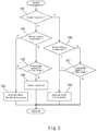
- FIG. 3 is a flowchart of exemplary operations performed by the remote inspection device 1 of the present invention.
- the process begins at step 101 where operator 3 triggers the remote controller 2 to initiate a remote inspection and the remote controller 2 determines if the escalator 9 is undergoing an inspection. If not, flow proceeds to step 102 where the controller 2 determines if the sensor 6 detects the presence of a passenger approaching the escalator 9 entrance. If the sensor 6 detects the presence of a passenger approaching the escalator 9 entrance, the flow proceeds to step 105 to stop initiating the remote inspection. At step 105, the initiation of the remote inspection may be resumed manually by the operator 3.
- step 105 flow returns to step 101 to repeat the inspection initiation process.
- step 103 the operator 3 checks to see whether a passenger appears in the video image 10. If the operator 3 confirms that there is no passenger in the video image 10, flow proceeds to step 104 to initiate the remote inspection.
- the remote controller 2 transmits a signal to the escalator controller 8 to operate the escalator 9 in the remote inspection mode, which drives the escalator 9 at a slower speed.
- step 104 flow returns to step 101 to proceed to the steps performed during the remote visual inspection.
- the algorithm verifies that the escalator 9 is undergoing the remote inspection at step 101, followed by proceeding to step 106 where the controller 2 determines if the sensor 6 detects the presence of a passenger approaching the escalator 9 during the remote inspection.
- step 106 If the sensor 6 detects the presence of a passenger approaching the escalator 9 at step 106, flow proceeds to step 108 to interrupt the remote inspection.
- step 108 in response to the detection of the presence of a passenger at the escalator entrance, the escalator controller 8 sends a signal to interrupt the remote visual inspection to the remote controller 2 while resuming operation of the escalator 9 in the normal operation mode.
- the remote visual inspection may be resumed manually by the operator 3 if the operator 3 verifies that there is no passenger approaching the escalator entrance, followed by proceeding to step 101 to repeat process. Alternatively, it may be resumed automatically if the sensor 6 does not detect the presence of a passenger approaching the escalator 9 for a predetermined period of time, e.g., for one minute. The escalator operation may be switched back to the remote inspection mode when the remote inspection is resumed.
- step 106 if the sensor 6 does not detect the presence of a passenger approaching the escalator 9 during the remote inspection, flow proceeds to step 107 where the operator 3 can check to see whether a passenger appears in the video image 10 while carrying out the remote inspection visually. If the operator 3 finds a passenger in the video image 10 at step 107 despite no detection of the passenger at step 106, it follows that a fault has occurred in one of the sensor systems. In the unlikely event that the fault has occurred in the sensor 6, the operator 3 can interrupt the remote inspection manually to operate the escalator 9 in the normal operation mode. If there is no passenger captured in the video image at step 107, i.e., if the remote inspection is not interrupted by the operator 3 manually, flow proceeds to step 101 to repeat process. This algorithm continues until the remote inspection is terminated by the operator 3.
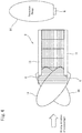
- FIG. 4 illustrates an embodiment using a pair of Doppler sensors as the sensors 6 for the remote inspection device 1 in accordance with the present invention.
- each of the pair of Doppler sensors 6, 6 is disposed in the vicinity of the end portion of the corresponding balustrade 11 at the escalator entrance.
- each of the pair of sensors 6, 6 is oriented at a predetermined angle toward the centerline of the escalator 9 so that the detection ranges 14, 14 of the pair of sensors 6, 6 overlap with one another at a predetermined position away from the end portions of the balustrades 11 at the escalator entrance or at a position away from the camera's view.
- the detection ranges 14, 14 may overlap at a position of one meter away from the camera's view.
- the detection range and orientation of the Doppler sensors 6 may be adjustable depending on the installation requirements of the escalator 9.
- a Doppler sensor as the sensor 6 makes it possible to detect moving direction of a passenger approaching the escalator entrance with a simple device.
- a Doppler sensor can identify not only a passenger trying to enter from a side of the escalator entrance, but also a person just crossing the detection area 14 of the sensor 6.
- the detection efficiency of a passenger approaching the entrance during a remote inspection is improved and unwanted interruptions of remove inspection can be prevented.
- the remote inspection device 1 can provide a quick switching of the escalator operation mode before the passenger reaches the escalator entrance.
- using a Doppler sensor is advantageous in that it enables a reliable detection of a passenger approaching the escalator entrance in an outdoor environment since a Doppler sensor is not influenced by sunlight and dust.
Landscapes
- Escalators And Moving Walkways (AREA)
Abstract
Description
- The present invention relates generally to a remote inspection of a passenger conveyor. In particular, the present invention relates to a remote inspection device and a method of performing a remote inspection for a passenger conveyor.
- Currently, periodic visual inspection of an escalator is not only carried out through an on-site inspection by maintenance personnel, but is also carried out through a remote inspection using at least one camera mounted directly above the vicinity of an entrance of the escalator. By performing a remote inspection, external defects of the escalator can be quickly detected such as abnormal movements or damages of steps or handrails of the escalator, the presence of a foreign matter caught between a comb and steps of the escalator, etc.
- When an operator at a remote maintenance center conducts a remote visual inspection, the operator first checks to see if there is no passenger on an escalator. Once the operator confirms that there is no passenger on the escalator, the operator manually switches the escalator's operation mode to an inspection mode which operates the escalator at a slower speed and performs a visual inspection through a video image of the escalator. If a passenger is getting on the escalator during the remote inspection, the operator switches the operation mode back to the normal operation mode manually.
- However, due to the limitation of the camera view, the operator may not notice the presence of the passenger just before riding on the escalator. Furthermore, since there is a slight time delay in transmission of the video image until the passenger appears on a display of the remote controller, there is a chance that the passenger had already been on the escalator when the operator noticed the presence of the passenger approaching the escalator entrance. In such an instance, if the escalator operation is switched back to the normal operation mode, the speed of the escalator is suddenly changed, which may result in serious accidents.
- Therefore, there exists in the art a need for providing an improved escalator remote inspection device capable of providing quick response to a passenger approaching an escalator entrance during a remote inspection.
- According to one aspect of the present invention, a remote inspection device for a passenger conveyor is disclosed. The remote inspection device includes at least one camera mounted directly above the passenger conveyor for monitoring external conditions of the passenger conveyor, a remote controller for performing a remote visual inspection using the camera, a passenger conveyor controller for operating the passenger conveyor at a normal speed during a normal operation and for operating the passenger conveyor at a slower speed or bringing it to a complete stop during a remote visual inspection, and a sensor connected to the passenger conveyor controller and arranged in the vicinity of the entrance of the passenger conveyor for detecting the presence of a passenger approaching the entrance of the passenger conveyor.
- The remote controller is connected to the passenger conveyor controller and the camera via remote access server. The passenger conveyor controller is configured to transmit a signal to the remote controller for interrupting the initiation of a remote visual inspection in response to the detection of a passenger approaching the entrance when initiating the remote visual inspection, and/or transmit a signal to the remote controller for interrupting the remote visual inspection and resume normal operation of the passenger conveyor in response to the detection of a passenger approaching the entrance during the remote visual inspection.
- In some embodiments, the sensor includes a pair of sensors arranged in the vicinity of the entrance side of balustrades on either side of the passenger conveyor.
- In some embodiments, each of the pair of sensors is oriented toward the approaching direction of a passenger and its detection range extends in a direction away from the passenger conveyor so that the sensor can detect a passenger in an area out of the camera's view.
- In some embodiments, the sensor is arranged in a guidepost, a moving direction guide display or a guide fence disposed in a position spaced apart from the passenger conveyor.
- In some embodiments, the sensor includes a Doppler sensor.
- In some embodiments, the Doppler sensor includes a pair of Doppler sensors arranged in the vicinity of the entrance side of balustrades on either side of the passenger conveyor.
- In some embodiments, each of the pair of Doppler sensors is oriented at a predetermined angle toward the centerline of the passenger conveyor so that the detection ranges of the pair of the Doppler sensors overlap with one another at a predetermined position away from the camera's view.
- In some embodiments, the Doppler sensor is arranged to detect moving direction of a passenger approaching the entrance of the passenger conveyor.
- In some embodiments, at least one camera is mounted directly above the entrance of the passenger conveyor.
- According to another aspect of the present invention, a method of performing a remote inspection for a passenger conveyor is disclosed. The method includes monitoring the presence of a passenger approaching an entrance of the passenger conveyor using a sensor arranged in the vicinity of the entrance of the passenger conveyor, performing a remote visual inspection of external conditions of the passenger conveyor using at least one camera mounted directly above the passenger conveyor if no passenger is detected by the sensor, operating the passenger conveyor at a slower speed or bringing it to a complete stop during the remote visual inspection, and interrupting the remote visual inspection and resuming operation of the passenger conveyor at a normal speed if the sensor detects the presence of a passenger approaching the entrance during the remote visual inspection.
- In some embodiments, performing a remote visual inspection further includes monitoring if a passenger appears in the camera's view, and the method further includes interrupting the remote visual inspection and resuming operation of the passenger conveyor at a normal speed if an operator finds a passenger appeared in the camera's view.
- In some embodiments, the method further includes resuming the remote visual inspection and operation of the passenger conveyor at the slower speed if the sensor does not detect the presence of a passenger approaching the entrance for a predetermined period of time.
- In some embodiments, resuming the remote visual inspection is performed if the sensor does not detect the presence of a passenger for one minute.
- In some embodiments, resuming the remote visual inspection is performed manually.
- In some embodiments, the sensor includes a pair of sensors arranged in the vicinity of the entrance side of balustrades on either side of the passenger conveyor.
- In some embodiments, each of the pair of sensors is oriented toward the approaching direction of a passenger and its detection range extends in a direction away from the passenger conveyor so that the sensor can detect a passenger in an area out of the camera's view.
- In some embodiments, the sensor is arranged in a guidepost, a moving direction guide display or a guide fence disposed in a position spaced apart from the passenger conveyor.
- In some embodiments, the sensor includes a Doppler sensor.
- In some embodiments, the Doppler sensor includes a pair of Doppler sensors arranged in the vicinity of the entrance side of balustrades on either side of the passenger conveyor.
- In some embodiments, the Doppler sensor is arranged to detect moving direction of a passenger approaching the entrance of the passenger conveyor.
- In some embodiments, at least one camera is mounted directly above the entrance of the passenger conveyor.
- These and other aspects of this disclosure will become more readily apparent from the following description and the accompanying drawings, which can be briefly described as follows.
-
-
Figure 1 is a schematic view showing one possible arrangement of a remote inspection device for an escalator in accordance with the present invention. -
Figure 2 is a schematic view showing one possible arrangement of a pair of sensors for detecting a passenger approaching an escalator entrance during a remote visual inspection, in accordance with the present invention. -
Figure 3 is a flow diagram of exemplary operations performed by the remote inspection device in accordance with the present invention. -
Figure 4 illustrates an embodiment of the remote inspection device using a pair of Doppler sensors. -
Figure 1 shows a schematic diagram of a remote inspection device 1 for an escalator in accordance with the present invention. The remote inspection device 1 includes aremote controller 2 for performing a remote visual inspection by anoperator 3, at least onecamera 4 for monitoring external conditions of theescalator 9, and asensor 6 for detecting the appearance of a passenger approaching the entrance of theescalator 9. Thecamera 4 is basically mounted directly above the entrance of theescalator 9 and configured to monitor the external condition of steps and handrails of theescalator 9. Thecamera 4 may also comprise arecorder 5 for storing video images. Thecamera 4 is connected through a remote access server 7 to theremote controller 2 and configured to displayvideo images 10 on a display of theremote controller 2. Although asingle camera 4 is shown inFIG. 1 that is disposed directly above the entrance of theescalator 9 moving in an upward direction, the remote inspection device 1 of the present invention may include twocameras 4 arranged directly above the landings on either end of theescalator 9. The twocameras 4 may be configured to monitor external conditions of the escalator around the escalator entrance depending on the moving direction of theescalator 9. The remote inspection device 1 may further include a plurality ofcameras 4 depending on the entire length of theescalator 9. - As shown in
FIG. 1 , theremote controller 2 is connected to theescalator controller 8 via the remote access server 7, and configured to switch the escalator operation between the normal operation mode and the remote inspection operation mode which operates theescalator 9 at a slower speed in response to an initiation of a remote visual inspection of theescalator 9. Further, thesensor 6 is connected to theescalator controller 8 for detecting a passenger approaching the escalator entrance during the remote inspection. Theescalator controller 8 is configured to transmit a signal to theremote controller 2 for interrupting the remote visual inspection and resume normal operation of theescalator 9, in response to the presence of a passenger detected by thesensor 6, as described later. -
Figure 2 shows an arrangement of thesensor 6 for detecting a passenger approaching the escalator entrance during the remote visual inspection, in accordance with the present invention. In one example, a pair ofsensors balustrades sensors 6 is arranged near theinlet guard 12 of thecorresponding handrail 13 on each side of theescalator 9. It should be understood that thesensor 6 may be any sensor capable of sensing the appearance of a passenger approaching the escalator entrance, such as a reflected light detection sensor, an ultrasonic sensor, an infrared radiation sensor, a Doppler sensor, etc. Preferably, each of the pair ofsensors 6 arranged on thecorresponding balustrade 11 is oriented toward the approaching direction of a passenger and its detection range extends in a divergent manner in a direction away from theescalator 9 so that thesensor 6 can detect a passenger before entering into a range that can be recognized by thecamera 4. In another example, thesensor 6 may be disposed in a guidepost, a moving direction guide display or a guide fence disposed in a position spaced apart from theescalator 9. In a further example, thesensor 6 may be placed on the ceiling near the escalator entrance. It should be understood thatvarious sensors 6 at various locations may be alternatively or additionally be provided. - Next, the remote visual inspection method of an escalator using the remote inspection device 1 in accordance with the present invention will be described.
-
Figure 3 is a flowchart of exemplary operations performed by the remote inspection device 1 of the present invention. The process begins atstep 101 whereoperator 3 triggers theremote controller 2 to initiate a remote inspection and theremote controller 2 determines if theescalator 9 is undergoing an inspection. If not, flow proceeds to step 102 where thecontroller 2 determines if thesensor 6 detects the presence of a passenger approaching theescalator 9 entrance. If thesensor 6 detects the presence of a passenger approaching theescalator 9 entrance, the flow proceeds to step 105 to stop initiating the remote inspection. Atstep 105, the initiation of the remote inspection may be resumed manually by theoperator 3. Alternatively, it may be resumed automatically if thesensor 6 does not detect the presence of a passenger approaching theescalator 9 for a predetermined period of time, e.g., for one minute. Following the execution ofstep 105, flow returns to step 101 to repeat the inspection initiation process. - If the
sensor 6 does not detect the presence of a passenger atstep 102, then the flow proceeds to step 103 where theoperator 3 checks to see whether a passenger appears in thevideo image 10. If theoperator 3 confirms that there is no passenger in thevideo image 10, flow proceeds to step 104 to initiate the remote inspection. In response to the initiation of the remote inspection atstep 104, theremote controller 2 transmits a signal to theescalator controller 8 to operate theescalator 9 in the remote inspection mode, which drives theescalator 9 at a slower speed. Following the execution ofstep 104, flow returns to step 101 to proceed to the steps performed during the remote visual inspection. - During the remote inspection, the algorithm verifies that the
escalator 9 is undergoing the remote inspection atstep 101, followed by proceeding to step 106 where thecontroller 2 determines if thesensor 6 detects the presence of a passenger approaching theescalator 9 during the remote inspection. - If the
sensor 6 detects the presence of a passenger approaching theescalator 9 atstep 106, flow proceeds to step 108 to interrupt the remote inspection. Atstep 108, in response to the detection of the presence of a passenger at the escalator entrance, theescalator controller 8 sends a signal to interrupt the remote visual inspection to theremote controller 2 while resuming operation of theescalator 9 in the normal operation mode. - At
step 108, the remote visual inspection may be resumed manually by theoperator 3 if theoperator 3 verifies that there is no passenger approaching the escalator entrance, followed by proceeding to step 101 to repeat process. Alternatively, it may be resumed automatically if thesensor 6 does not detect the presence of a passenger approaching theescalator 9 for a predetermined period of time, e.g., for one minute. The escalator operation may be switched back to the remote inspection mode when the remote inspection is resumed. - Again, at
step 106, if thesensor 6 does not detect the presence of a passenger approaching theescalator 9 during the remote inspection, flow proceeds to step 107 where theoperator 3 can check to see whether a passenger appears in thevideo image 10 while carrying out the remote inspection visually. If theoperator 3 finds a passenger in thevideo image 10 atstep 107 despite no detection of the passenger atstep 106, it follows that a fault has occurred in one of the sensor systems. In the unlikely event that the fault has occurred in thesensor 6, theoperator 3 can interrupt the remote inspection manually to operate theescalator 9 in the normal operation mode. If there is no passenger captured in the video image atstep 107, i.e., if the remote inspection is not interrupted by theoperator 3 manually, flow proceeds to step 101 to repeat process. This algorithm continues until the remote inspection is terminated by theoperator 3. - With such a configuration, it is possible to appropriately perform switching of the escalator operation mode between the normal operation mode and the remote inspection mode during a remote visual inspection. Thus, the potential risk of a serious accident associated with sudden speed changes of the escalator can be avoided even if a passenger is getting on the
escalator 9 during a remote inspection. -
Figure 4 illustrates an embodiment using a pair of Doppler sensors as thesensors 6 for the remote inspection device 1 in accordance with the present invention. As shown inFIG. 4 , each of the pair ofDoppler sensors balustrade 11 at the escalator entrance. In particular, as shown inFIG. 4 , each of the pair ofsensors escalator 9 so that the detection ranges 14, 14 of the pair ofsensors balustrades 11 at the escalator entrance or at a position away from the camera's view. For example, the detection ranges 14, 14 may overlap at a position of one meter away from the camera's view. It should be understood that the detection range and orientation of theDoppler sensors 6 may be adjustable depending on the installation requirements of theescalator 9. - Using a Doppler sensor as the
sensor 6 makes it possible to detect moving direction of a passenger approaching the escalator entrance with a simple device. In particular, a Doppler sensor can identify not only a passenger trying to enter from a side of the escalator entrance, but also a person just crossing thedetection area 14 of thesensor 6. Thus, the detection efficiency of a passenger approaching the entrance during a remote inspection is improved and unwanted interruptions of remove inspection can be prevented. - Furthermore, since a Doppler sensor can detect the presence of a passenger approaching the escalator entrance over a relatively wide range in comparison with other sensor devices, the remote inspection device 1 can provide a quick switching of the escalator operation mode before the passenger reaches the escalator entrance. Especially, using a Doppler sensor is advantageous in that it enables a reliable detection of a passenger approaching the escalator entrance in an outdoor environment since a Doppler sensor is not influenced by sunlight and dust.
- Although the present invention is described with referenced to the
escalator 9, it should be understood that the present invention may be applied to any passenger conveyor such as a moving walkway. - While the present invention has been particularly shown and described with reference to the exemplary embodiments as illustrated in the drawings, it will be recognized by those skilled in the art that various modifications may be made without departing from the spirit and scope of the invention as disclosed in the accompanying claims.
Claims (15)
- A remote inspection device for a passenger conveyor, comprising:at least one camera mounted directly above the passenger conveyor for monitoring external conditions of the passenger conveyor;a remote controller for performing a remote visual inspection using the camera;a passenger conveyor controller for operating the passenger conveyor at a normal speed during a normal operation and for operating the passenger conveyor at a slower speed or bringing it to a complete stop during a remote visual inspection; anda sensor connected to the passenger conveyor controller and arranged in the vicinity of the entrance of the passenger conveyor for detecting the presence of a passenger approaching the entrance of the passenger conveyor,wherein the remote controller is connected to the passenger conveyor controller and the camera via remote access server, andwherein the passenger conveyor controller is configured to transmit a signal to the remote controller for interrupting the initiation of a remote visual inspection in response to the detection of a passenger approaching the entrance when initiating the remote visual inspection, and/or transmit a signal to the remote controller for interrupting the remote visual inspection and resume normal operation of the passenger conveyor in response to the detection of a passenger approaching the entrance during the remote visual inspection.
- The remote inspection device of claim 1, wherein the sensor includes a pair of sensors arranged in the vicinity of the entrance side of balustrades on either side of the passenger conveyor.
- The remote inspection device of claim 2, wherein each of the pair of sensors is oriented toward the approaching direction of a passenger and its detection range extends in a direction away from the passenger conveyor so that the sensor can detect a passenger in an area out of the camera's view.
- The remote inspection device of claim 1 2 or 3, wherein the sensor is arranged in a guidepost, a moving direction guide display or a guide fence disposed in a position spaced apart from the passenger conveyor.
- The remote inspection device of any preceding claim, wherein the sensor includes a Doppler sensor.
- The remote inspection device of claim 5, wherein the Doppler sensor includes a pair of Doppler sensors arranged in the vicinity of the entrance side of balustrades on either side of the passenger conveyor.
- The remote inspection device of claim 6, wherein each of the pair of Doppler sensors is oriented at a predetermined angle toward the centerline of the passenger conveyor so that the detection ranges of the pair of the Doppler sensors overlap with one another at a predetermined position away from the camera's view.
- The remote inspection device of claim 5, 6 or 7, wherein the Doppler sensor is arranged to detect moving direction of a passenger approaching the entrance of the passenger conveyor.
- The remote inspection device of any preceding claim, wherein the at least one camera is mounted directly above the entrance of the passenger conveyor.
- A method of performing a remote inspection for a passenger conveyor, the method comprising:monitoring the presence of a passenger approaching an entrance of the passenger conveyor using a sensor arranged in the vicinity of the entrance of the passenger conveyor;performing a remote visual inspection of external conditions of the passenger conveyor using at least one camera mounted directly above the passenger conveyor, if no passenger is detected by the sensor;operating the passenger conveyor at a slower speed or bringing it to a complete stop during the remote visual inspection; andinterrupting the remote visual inspection and resuming operation of the passenger conveyor at a normal speed, if the sensor detects the presence of a passenger approaching the entrance during the remote visual inspection.
- The method of claim 10, wherein performing a remote visual inspection further includes monitoring if a passenger appears in the camera's view, and further including:
interrupting the remote visual inspection and resuming operation of the passenger conveyor at a normal speed, if an operator finds a passenger appeared in the camera's view. - The method of claim 10 or 11, further comprising:
resuming the remote visual inspection and operation of the passenger conveyor at the slower speed if the sensor does not detect the presence of a passenger approaching the entrance for a predetermined period of time. - The method of claim 12, wherein resuming the remote visual inspection is performed if the sensor does not detect the presence of a passenger for one minute.
- The method of claim 12, wherein resuming the remote visual inspection is performed manually.
- The method of claim 10, wherein the sensor includes a pair of sensors arranged in the vicinity of the entrance side of balustrades on either side of the passenger conveyor; preferably wherein each of the pair of sensors is oriented toward the approaching direction of a passenger and its detection range extends in a direction away from the passenger conveyor so that the sensor can detect a passenger in an area out of the camera's view.
Applications Claiming Priority (1)
| Application Number | Priority Date | Filing Date | Title |
|---|---|---|---|
| US15/834,637 US10093518B1 (en) | 2017-12-07 | 2017-12-07 | Remote inspection of passenger conveyors |
Publications (2)
| Publication Number | Publication Date |
|---|---|
| EP3495307A1 true EP3495307A1 (en) | 2019-06-12 |
| EP3495307B1 EP3495307B1 (en) | 2022-04-13 |
Family
ID=63685273
Family Applications (1)
| Application Number | Title | Priority Date | Filing Date |
|---|---|---|---|
| EP18211123.7A Active EP3495307B1 (en) | 2017-12-07 | 2018-12-07 | Remote inspection of passenger conveyors |
Country Status (3)
| Country | Link |
|---|---|
| US (1) | US10093518B1 (en) |
| EP (1) | EP3495307B1 (en) |
| CN (1) | CN109896406B (en) |
Families Citing this family (5)
| Publication number | Priority date | Publication date | Assignee | Title |
|---|---|---|---|---|
| JP7114624B2 (en) * | 2017-03-28 | 2022-08-08 | インベンテイオ・アクテイエンゲゼルシヤフト | Monitoring the mechanical condition of escalators or moving walkways |
| JP6522203B1 (en) * | 2018-05-16 | 2019-05-29 | 東芝エレベータ株式会社 | Passenger conveyor anomaly detection system |
| JP7731220B2 (en) * | 2021-05-18 | 2025-08-29 | 三菱電機株式会社 | Passenger conveyor and its control device |
| CN116812725A (en) * | 2023-07-27 | 2023-09-29 | 上海爱登堡电梯集团股份有限公司 | A smart camera-based escalator remote control device and its control method |
| CN121317506B (en) * | 2025-12-11 | 2026-03-03 | 康力电梯股份有限公司 | Escalator remote function safety device based on safety PLC and control method |
Citations (4)
| Publication number | Priority date | Publication date | Assignee | Title |
|---|---|---|---|---|
| GB2312057A (en) * | 1996-04-08 | 1997-10-15 | Hitachi Ltd | Supervisory system for passenger conveyer |
| JP2007070061A (en) * | 2005-09-07 | 2007-03-22 | Hitachi Building Systems Co Ltd | Passenger conveyor operation management device |
| JP2009035339A (en) * | 2007-07-31 | 2009-02-19 | Mitsubishi Electric Building Techno Service Co Ltd | Control device of passenger conveyor and control method |
| JP2009155050A (en) * | 2007-12-27 | 2009-07-16 | Hitachi Ltd | Automatic diagnostic operation device for passenger conveyor |
Family Cites Families (17)
| Publication number | Priority date | Publication date | Assignee | Title |
|---|---|---|---|---|
| FR2591000B1 (en) | 1985-11-29 | 1988-09-23 | Spie Batignolles | ASSISTANCE DEVICE FOR THE MAINTENANCE OF AN ELECTROMECHANICAL INSTALLATION WHICH INCLUDES AUTOMATIC CONTROL AND CONTROL MEANS |
| DE3611597A1 (en) | 1986-04-07 | 1987-10-08 | Flohr Otis Aufzugs Gmbh | Central remote escalator monitoring arrangement |
| JP3400669B2 (en) * | 1997-02-26 | 2003-04-28 | 三菱電機ビルテクノサービス株式会社 | Remote monitoring system |
| JP2000255964A (en) * | 1999-03-08 | 2000-09-19 | Hitachi Ltd | Escalator monitoring device |
| ATE305898T1 (en) * | 1999-05-17 | 2005-10-15 | Mitsubishi Electric Corp | CONTROL FOR PASSENGER CONVEYOR AND PASSENGER SENSOR |
| US6267219B1 (en) * | 2000-08-11 | 2001-07-31 | Otis Elevator Company | Electronic safety system for escalators |
| US7002462B2 (en) * | 2001-02-20 | 2006-02-21 | Gannett Fleming | System and method for remote monitoring and maintenance management of vertical transportation equipment |
| RU2346877C2 (en) * | 2003-05-28 | 2009-02-20 | Инвенцио Аг | Method of servicing elevators or escalators |
| ZA200409385B (en) * | 2003-12-08 | 2005-09-28 | Inventio Ag | Equipment for monitoring the space in front of escalators and moving walkways by high-frequency sensors |
| JP4504407B2 (en) | 2007-09-25 | 2010-07-14 | 株式会社日立製作所 | Chain sag diagnostic apparatus and method for passenger conveyor |
| FI121465B (en) * | 2009-08-25 | 2010-11-30 | Kone Corp | Transport systems |
| CN101695983B (en) * | 2009-10-23 | 2011-12-21 | 浙江工业大学 | Omnibearing computer vision based energy-saving and safety monitoring system of escalator |
| IT1399129B1 (en) | 2010-04-01 | 2013-04-05 | Paoletti | MODULAR ADAPTIVE SURVEILLANCE SYSTEM FOR MEANS PERSONAL STRUCTURES |
| CN103052587B (en) * | 2010-08-20 | 2016-03-30 | 奥的斯电梯公司 | Remotely controlled passenger conveyor and method for remotely controlling passenger conveyor |
| CN202030423U (en) | 2011-01-27 | 2011-11-09 | 许昌西继电梯有限公司 | Escalator monitoring device |
| CN103267978A (en) | 2013-04-16 | 2013-08-28 | 焦海宁 | Hidden microwave active imaging personal security inspection system |
| CN106660756A (en) * | 2014-05-06 | 2017-05-10 | 奥的斯电梯公司 | Object detector, and method for controlling a passenger conveyor system using the same |
-
2017
- 2017-12-07 US US15/834,637 patent/US10093518B1/en active Active
-
2018
- 2018-12-06 CN CN201811491036.9A patent/CN109896406B/en active Active
- 2018-12-07 EP EP18211123.7A patent/EP3495307B1/en active Active
Patent Citations (4)
| Publication number | Priority date | Publication date | Assignee | Title |
|---|---|---|---|---|
| GB2312057A (en) * | 1996-04-08 | 1997-10-15 | Hitachi Ltd | Supervisory system for passenger conveyer |
| JP2007070061A (en) * | 2005-09-07 | 2007-03-22 | Hitachi Building Systems Co Ltd | Passenger conveyor operation management device |
| JP2009035339A (en) * | 2007-07-31 | 2009-02-19 | Mitsubishi Electric Building Techno Service Co Ltd | Control device of passenger conveyor and control method |
| JP2009155050A (en) * | 2007-12-27 | 2009-07-16 | Hitachi Ltd | Automatic diagnostic operation device for passenger conveyor |
Also Published As
| Publication number | Publication date |
|---|---|
| US10093518B1 (en) | 2018-10-09 |
| CN109896406A (en) | 2019-06-18 |
| EP3495307B1 (en) | 2022-04-13 |
| CN109896406B (en) | 2020-08-25 |
Similar Documents
| Publication | Publication Date | Title |
|---|---|---|
| EP3495307B1 (en) | Remote inspection of passenger conveyors | |
| US6550585B2 (en) | Hoistway intrusion detection | |
| JP5249529B2 (en) | Passenger conveyor safety device and safety control method | |
| US10427915B2 (en) | Method for controlling a transport device, namely an escalator or a moving walkway | |
| EP3533747B1 (en) | Passenger conveyor | |
| JP6066774B2 (en) | Passenger conveyor | |
| CN204281016U (en) | Passenger conveyors | |
| JP5199564B2 (en) | Passenger conveyor | |
| CN206156559U (en) | Handrail area protection device | |
| JP2009035339A (en) | Control device of passenger conveyor and control method | |
| EP1357077A1 (en) | Passenger conveyer controller and operation control method | |
| JP2013245083A (en) | Passenger conveyor and method of controlling the same | |
| JP5380819B2 (en) | Elevator door control device | |
| JP5778075B2 (en) | Passenger conveyor operation control system and operation control method | |
| EP3805141B1 (en) | Passenger detection system for a passenger moving system | |
| CN118529584A (en) | Safety protection device and escalator | |
| CN211169468U (en) | Maintenance and inspection work support system for passenger conveyor | |
| JP5963251B2 (en) | Situation judging device and situation judging program | |
| WO2003097507A1 (en) | Automatic operating unit of man conveyor | |
| KR102618108B1 (en) | Protection against wind system for boarding bridge and control method | |
| JP2000109282A (en) | Safety device for passenger conveying device | |
| US20250033934A1 (en) | Brake system for a conveyor system, method for detecting a brake of a conveyor system, and controller | |
| SG186544A1 (en) | Elevator-use electronic safety assurance control apparatus | |
| JP6480352B2 (en) | Passenger conveyor and control method thereof | |
| JPS63269298A (en) | Abnormality detector |
Legal Events
| Date | Code | Title | Description |
|---|---|---|---|
| PUAI | Public reference made under article 153(3) epc to a published international application that has entered the european phase |
Free format text: ORIGINAL CODE: 0009012 |
|
| STAA | Information on the status of an ep patent application or granted ep patent |
Free format text: STATUS: THE APPLICATION HAS BEEN PUBLISHED |
|
| AK | Designated contracting states |
Kind code of ref document: A1 Designated state(s): AL AT BE BG CH CY CZ DE DK EE ES FI FR GB GR HR HU IE IS IT LI LT LU LV MC MK MT NL NO PL PT RO RS SE SI SK SM TR |
|
| AX | Request for extension of the european patent |
Extension state: BA ME |
|
| STAA | Information on the status of an ep patent application or granted ep patent |
Free format text: STATUS: REQUEST FOR EXAMINATION WAS MADE |
|
| 17P | Request for examination filed |
Effective date: 20191212 |
|
| RBV | Designated contracting states (corrected) |
Designated state(s): AL AT BE BG CH CY CZ DE DK EE ES FI FR GB GR HR HU IE IS IT LI LT LU LV MC MK MT NL NO PL PT RO RS SE SI SK SM TR |
|
| RIC1 | Information provided on ipc code assigned before grant |
Ipc: B66B 25/00 20060101AFI20210225BHEP |
|
| GRAP | Despatch of communication of intention to grant a patent |
Free format text: ORIGINAL CODE: EPIDOSNIGR1 |
|
| STAA | Information on the status of an ep patent application or granted ep patent |
Free format text: STATUS: GRANT OF PATENT IS INTENDED |
|
| INTG | Intention to grant announced |
Effective date: 20210504 |
|
| GRAJ | Information related to disapproval of communication of intention to grant by the applicant or resumption of examination proceedings by the epo deleted |
Free format text: ORIGINAL CODE: EPIDOSDIGR1 |
|
| STAA | Information on the status of an ep patent application or granted ep patent |
Free format text: STATUS: REQUEST FOR EXAMINATION WAS MADE |
|
| GRAP | Despatch of communication of intention to grant a patent |
Free format text: ORIGINAL CODE: EPIDOSNIGR1 |
|
| STAA | Information on the status of an ep patent application or granted ep patent |
Free format text: STATUS: GRANT OF PATENT IS INTENDED |
|
| INTC | Intention to grant announced (deleted) | ||
| INTG | Intention to grant announced |
Effective date: 20211026 |
|
| GRAS | Grant fee paid |
Free format text: ORIGINAL CODE: EPIDOSNIGR3 |
|
| GRAA | (expected) grant |
Free format text: ORIGINAL CODE: 0009210 |
|
| STAA | Information on the status of an ep patent application or granted ep patent |
Free format text: STATUS: THE PATENT HAS BEEN GRANTED |
|
| AK | Designated contracting states |
Kind code of ref document: B1 Designated state(s): AL AT BE BG CH CY CZ DE DK EE ES FI FR GB GR HR HU IE IS IT LI LT LU LV MC MK MT NL NO PL PT RO RS SE SI SK SM TR |
|
| REG | Reference to a national code |
Ref country code: GB Ref legal event code: FG4D |
|
| REG | Reference to a national code |
Ref country code: CH Ref legal event code: EP |
|
| REG | Reference to a national code |
Ref country code: DE Ref legal event code: R096 Ref document number: 602018033708 Country of ref document: DE |
|
| REG | Reference to a national code |
Ref country code: IE Ref legal event code: FG4D |
|
| REG | Reference to a national code |
Ref country code: AT Ref legal event code: REF Ref document number: 1483285 Country of ref document: AT Kind code of ref document: T Effective date: 20220515 |
|
| REG | Reference to a national code |
Ref country code: LT Ref legal event code: MG9D |
|
| REG | Reference to a national code |
Ref country code: NL Ref legal event code: MP Effective date: 20220413 |
|
| REG | Reference to a national code |
Ref country code: AT Ref legal event code: MK05 Ref document number: 1483285 Country of ref document: AT Kind code of ref document: T Effective date: 20220413 |
|
| PG25 | Lapsed in a contracting state [announced via postgrant information from national office to epo] |
Ref country code: NL Free format text: LAPSE BECAUSE OF FAILURE TO SUBMIT A TRANSLATION OF THE DESCRIPTION OR TO PAY THE FEE WITHIN THE PRESCRIBED TIME-LIMIT Effective date: 20220413 |
|
| PG25 | Lapsed in a contracting state [announced via postgrant information from national office to epo] |
Ref country code: SE Free format text: LAPSE BECAUSE OF FAILURE TO SUBMIT A TRANSLATION OF THE DESCRIPTION OR TO PAY THE FEE WITHIN THE PRESCRIBED TIME-LIMIT Effective date: 20220413 Ref country code: PT Free format text: LAPSE BECAUSE OF FAILURE TO SUBMIT A TRANSLATION OF THE DESCRIPTION OR TO PAY THE FEE WITHIN THE PRESCRIBED TIME-LIMIT Effective date: 20220816 Ref country code: NO Free format text: LAPSE BECAUSE OF FAILURE TO SUBMIT A TRANSLATION OF THE DESCRIPTION OR TO PAY THE FEE WITHIN THE PRESCRIBED TIME-LIMIT Effective date: 20220713 Ref country code: LT Free format text: LAPSE BECAUSE OF FAILURE TO SUBMIT A TRANSLATION OF THE DESCRIPTION OR TO PAY THE FEE WITHIN THE PRESCRIBED TIME-LIMIT Effective date: 20220413 Ref country code: HR Free format text: LAPSE BECAUSE OF FAILURE TO SUBMIT A TRANSLATION OF THE DESCRIPTION OR TO PAY THE FEE WITHIN THE PRESCRIBED TIME-LIMIT Effective date: 20220413 Ref country code: GR Free format text: LAPSE BECAUSE OF FAILURE TO SUBMIT A TRANSLATION OF THE DESCRIPTION OR TO PAY THE FEE WITHIN THE PRESCRIBED TIME-LIMIT Effective date: 20220714 Ref country code: FI Free format text: LAPSE BECAUSE OF FAILURE TO SUBMIT A TRANSLATION OF THE DESCRIPTION OR TO PAY THE FEE WITHIN THE PRESCRIBED TIME-LIMIT Effective date: 20220413 Ref country code: ES Free format text: LAPSE BECAUSE OF FAILURE TO SUBMIT A TRANSLATION OF THE DESCRIPTION OR TO PAY THE FEE WITHIN THE PRESCRIBED TIME-LIMIT Effective date: 20220413 Ref country code: BG Free format text: LAPSE BECAUSE OF FAILURE TO SUBMIT A TRANSLATION OF THE DESCRIPTION OR TO PAY THE FEE WITHIN THE PRESCRIBED TIME-LIMIT Effective date: 20220713 Ref country code: AT Free format text: LAPSE BECAUSE OF FAILURE TO SUBMIT A TRANSLATION OF THE DESCRIPTION OR TO PAY THE FEE WITHIN THE PRESCRIBED TIME-LIMIT Effective date: 20220413 |
|
| PG25 | Lapsed in a contracting state [announced via postgrant information from national office to epo] |
Ref country code: RS Free format text: LAPSE BECAUSE OF FAILURE TO SUBMIT A TRANSLATION OF THE DESCRIPTION OR TO PAY THE FEE WITHIN THE PRESCRIBED TIME-LIMIT Effective date: 20220413 Ref country code: PL Free format text: LAPSE BECAUSE OF FAILURE TO SUBMIT A TRANSLATION OF THE DESCRIPTION OR TO PAY THE FEE WITHIN THE PRESCRIBED TIME-LIMIT Effective date: 20220413 Ref country code: LV Free format text: LAPSE BECAUSE OF FAILURE TO SUBMIT A TRANSLATION OF THE DESCRIPTION OR TO PAY THE FEE WITHIN THE PRESCRIBED TIME-LIMIT Effective date: 20220413 Ref country code: IS Free format text: LAPSE BECAUSE OF FAILURE TO SUBMIT A TRANSLATION OF THE DESCRIPTION OR TO PAY THE FEE WITHIN THE PRESCRIBED TIME-LIMIT Effective date: 20220813 |
|
| REG | Reference to a national code |
Ref country code: DE Ref legal event code: R097 Ref document number: 602018033708 Country of ref document: DE |
|
| PG25 | Lapsed in a contracting state [announced via postgrant information from national office to epo] |
Ref country code: SM Free format text: LAPSE BECAUSE OF FAILURE TO SUBMIT A TRANSLATION OF THE DESCRIPTION OR TO PAY THE FEE WITHIN THE PRESCRIBED TIME-LIMIT Effective date: 20220413 Ref country code: SK Free format text: LAPSE BECAUSE OF FAILURE TO SUBMIT A TRANSLATION OF THE DESCRIPTION OR TO PAY THE FEE WITHIN THE PRESCRIBED TIME-LIMIT Effective date: 20220413 Ref country code: RO Free format text: LAPSE BECAUSE OF FAILURE TO SUBMIT A TRANSLATION OF THE DESCRIPTION OR TO PAY THE FEE WITHIN THE PRESCRIBED TIME-LIMIT Effective date: 20220413 Ref country code: EE Free format text: LAPSE BECAUSE OF FAILURE TO SUBMIT A TRANSLATION OF THE DESCRIPTION OR TO PAY THE FEE WITHIN THE PRESCRIBED TIME-LIMIT Effective date: 20220413 Ref country code: DK Free format text: LAPSE BECAUSE OF FAILURE TO SUBMIT A TRANSLATION OF THE DESCRIPTION OR TO PAY THE FEE WITHIN THE PRESCRIBED TIME-LIMIT Effective date: 20220413 Ref country code: CZ Free format text: LAPSE BECAUSE OF FAILURE TO SUBMIT A TRANSLATION OF THE DESCRIPTION OR TO PAY THE FEE WITHIN THE PRESCRIBED TIME-LIMIT Effective date: 20220413 |
|
| PLBE | No opposition filed within time limit |
Free format text: ORIGINAL CODE: 0009261 |
|
| STAA | Information on the status of an ep patent application or granted ep patent |
Free format text: STATUS: NO OPPOSITION FILED WITHIN TIME LIMIT |
|
| 26N | No opposition filed |
Effective date: 20230116 |
|
| PG25 | Lapsed in a contracting state [announced via postgrant information from national office to epo] |
Ref country code: AL Free format text: LAPSE BECAUSE OF FAILURE TO SUBMIT A TRANSLATION OF THE DESCRIPTION OR TO PAY THE FEE WITHIN THE PRESCRIBED TIME-LIMIT Effective date: 20220413 |
|
| PG25 | Lapsed in a contracting state [announced via postgrant information from national office to epo] |
Ref country code: SI Free format text: LAPSE BECAUSE OF FAILURE TO SUBMIT A TRANSLATION OF THE DESCRIPTION OR TO PAY THE FEE WITHIN THE PRESCRIBED TIME-LIMIT Effective date: 20220413 |
|
| REG | Reference to a national code |
Ref country code: CH Ref legal event code: PL |
|
| GBPC | Gb: european patent ceased through non-payment of renewal fee |
Effective date: 20221207 |
|
| REG | Reference to a national code |
Ref country code: BE Ref legal event code: MM Effective date: 20221231 |
|
| PG25 | Lapsed in a contracting state [announced via postgrant information from national office to epo] |
Ref country code: LU Free format text: LAPSE BECAUSE OF NON-PAYMENT OF DUE FEES Effective date: 20221207 |
|
| PG25 | Lapsed in a contracting state [announced via postgrant information from national office to epo] |
Ref country code: LI Free format text: LAPSE BECAUSE OF NON-PAYMENT OF DUE FEES Effective date: 20221231 Ref country code: IE Free format text: LAPSE BECAUSE OF NON-PAYMENT OF DUE FEES Effective date: 20221207 Ref country code: GB Free format text: LAPSE BECAUSE OF NON-PAYMENT OF DUE FEES Effective date: 20221207 Ref country code: CH Free format text: LAPSE BECAUSE OF NON-PAYMENT OF DUE FEES Effective date: 20221231 |
|
| PG25 | Lapsed in a contracting state [announced via postgrant information from national office to epo] |
Ref country code: BE Free format text: LAPSE BECAUSE OF NON-PAYMENT OF DUE FEES Effective date: 20221231 |
|
| PG25 | Lapsed in a contracting state [announced via postgrant information from national office to epo] |
Ref country code: IT Free format text: LAPSE BECAUSE OF FAILURE TO SUBMIT A TRANSLATION OF THE DESCRIPTION OR TO PAY THE FEE WITHIN THE PRESCRIBED TIME-LIMIT Effective date: 20220413 |
|
| PG25 | Lapsed in a contracting state [announced via postgrant information from national office to epo] |
Ref country code: HU Free format text: LAPSE BECAUSE OF FAILURE TO SUBMIT A TRANSLATION OF THE DESCRIPTION OR TO PAY THE FEE WITHIN THE PRESCRIBED TIME-LIMIT; INVALID AB INITIO Effective date: 20181207 |
|
| PG25 | Lapsed in a contracting state [announced via postgrant information from national office to epo] |
Ref country code: CY Free format text: LAPSE BECAUSE OF FAILURE TO SUBMIT A TRANSLATION OF THE DESCRIPTION OR TO PAY THE FEE WITHIN THE PRESCRIBED TIME-LIMIT Effective date: 20220413 |
|
| PG25 | Lapsed in a contracting state [announced via postgrant information from national office to epo] |
Ref country code: MK Free format text: LAPSE BECAUSE OF FAILURE TO SUBMIT A TRANSLATION OF THE DESCRIPTION OR TO PAY THE FEE WITHIN THE PRESCRIBED TIME-LIMIT Effective date: 20220413 |
|
| PG25 | Lapsed in a contracting state [announced via postgrant information from national office to epo] |
Ref country code: MC Free format text: LAPSE BECAUSE OF FAILURE TO SUBMIT A TRANSLATION OF THE DESCRIPTION OR TO PAY THE FEE WITHIN THE PRESCRIBED TIME-LIMIT Effective date: 20220413 |
|
| PG25 | Lapsed in a contracting state [announced via postgrant information from national office to epo] |
Ref country code: TR Free format text: LAPSE BECAUSE OF FAILURE TO SUBMIT A TRANSLATION OF THE DESCRIPTION OR TO PAY THE FEE WITHIN THE PRESCRIBED TIME-LIMIT Effective date: 20220413 Ref country code: MC Free format text: LAPSE BECAUSE OF FAILURE TO SUBMIT A TRANSLATION OF THE DESCRIPTION OR TO PAY THE FEE WITHIN THE PRESCRIBED TIME-LIMIT Effective date: 20220413 |
|
| PG25 | Lapsed in a contracting state [announced via postgrant information from national office to epo] |
Ref country code: MT Free format text: LAPSE BECAUSE OF FAILURE TO SUBMIT A TRANSLATION OF THE DESCRIPTION OR TO PAY THE FEE WITHIN THE PRESCRIBED TIME-LIMIT Effective date: 20220413 |
|
| PG25 | Lapsed in a contracting state [announced via postgrant information from national office to epo] |
Ref country code: BG Free format text: LAPSE BECAUSE OF FAILURE TO SUBMIT A TRANSLATION OF THE DESCRIPTION OR TO PAY THE FEE WITHIN THE PRESCRIBED TIME-LIMIT Effective date: 20220413 |
|
| PG25 | Lapsed in a contracting state [announced via postgrant information from national office to epo] |
Ref country code: BG Free format text: LAPSE BECAUSE OF FAILURE TO SUBMIT A TRANSLATION OF THE DESCRIPTION OR TO PAY THE FEE WITHIN THE PRESCRIBED TIME-LIMIT Effective date: 20220413 |
|
| PGFP | Annual fee paid to national office [announced via postgrant information from national office to epo] |
Ref country code: DE Payment date: 20251126 Year of fee payment: 8 |
|
| PGFP | Annual fee paid to national office [announced via postgrant information from national office to epo] |
Ref country code: FR Payment date: 20251120 Year of fee payment: 8 |