EP3495305A1 - End-fastening apparatus for lifting rope and elevator system using thereof - Google Patents
End-fastening apparatus for lifting rope and elevator system using thereof Download PDFInfo
- Publication number
- EP3495305A1 EP3495305A1 EP18201609.7A EP18201609A EP3495305A1 EP 3495305 A1 EP3495305 A1 EP 3495305A1 EP 18201609 A EP18201609 A EP 18201609A EP 3495305 A1 EP3495305 A1 EP 3495305A1
- Authority
- EP
- European Patent Office
- Prior art keywords
- pull rope
- hydraulic
- fixing apparatus
- head fixing
- piston
- Prior art date
- Legal status (The legal status is an assumption and is not a legal conclusion. Google has not performed a legal analysis and makes no representation as to the accuracy of the status listed.)
- Granted
Links
- 238000013016 damping Methods 0.000 claims description 15
- 238000001514 detection method Methods 0.000 claims description 11
- 229910000831 Steel Inorganic materials 0.000 claims description 8
- 239000010959 steel Substances 0.000 claims description 8
- 238000000034 method Methods 0.000 claims description 7
- 239000000835 fiber Substances 0.000 claims description 4
- 239000010720 hydraulic oil Substances 0.000 description 11
- 229920000049 Carbon (fiber) Polymers 0.000 description 8
- 239000004917 carbon fiber Substances 0.000 description 8
- 238000010586 diagram Methods 0.000 description 6
- VNWKTOKETHGBQD-UHFFFAOYSA-N methane Chemical compound C VNWKTOKETHGBQD-UHFFFAOYSA-N 0.000 description 5
- 230000003014 reinforcing effect Effects 0.000 description 4
- 239000012783 reinforcing fiber Substances 0.000 description 3
- 238000012423 maintenance Methods 0.000 description 2
- 239000000463 material Substances 0.000 description 2
- 229920002635 polyurethane Polymers 0.000 description 2
- 239000004814 polyurethane Substances 0.000 description 2
- 239000000758 substrate Substances 0.000 description 2
- 238000010521 absorption reaction Methods 0.000 description 1
- 230000004308 accommodation Effects 0.000 description 1
- 238000004891 communication Methods 0.000 description 1
- 239000007788 liquid Substances 0.000 description 1
- 238000012986 modification Methods 0.000 description 1
- 230000004048 modification Effects 0.000 description 1
- 239000003921 oil Substances 0.000 description 1
- 230000003068 static effect Effects 0.000 description 1
- 239000000126 substance Substances 0.000 description 1
Images

Classifications
-
- B—PERFORMING OPERATIONS; TRANSPORTING
- B66—HOISTING; LIFTING; HAULING
- B66B—ELEVATORS; ESCALATORS OR MOVING WALKWAYS
- B66B7/00—Other common features of elevators
- B66B7/06—Arrangements of ropes or cables
- B66B7/10—Arrangements of ropes or cables for equalising rope or cable tension
-
- B—PERFORMING OPERATIONS; TRANSPORTING
- B66—HOISTING; LIFTING; HAULING
- B66B—ELEVATORS; ESCALATORS OR MOVING WALKWAYS
- B66B7/00—Other common features of elevators
- B66B7/06—Arrangements of ropes or cables
- B66B7/08—Arrangements of ropes or cables for connection to the cars or cages, e.g. couplings
-
- B—PERFORMING OPERATIONS; TRANSPORTING
- B66—HOISTING; LIFTING; HAULING
- B66B—ELEVATORS; ESCALATORS OR MOVING WALKWAYS
- B66B9/00—Kinds or types of lifts in, or associated with, buildings or other structures
Definitions
- the present invention belongs to the technical field of elevators, and relates to a pull rope head fixing apparatus that can automatically balance the tensions of multiple pull ropes and an elevator system using the same.
- a pull rope is a common component in an elevator system, and is also a key component for the operation of the elevator system.
- the pull rope when being driven by a tractor of the elevator system, can be used for lifting a car or the like.
- multiple pull ropes are generally used to lift a car simultaneously, especially when the pull ropes are flat ropes (e.g., steel belts) with the width of the cross section greater than the thickness thereof.
- the multiple pull ropes are wound on, for example, a traction wheel and/or a sheave in parallel and may have different magnitudes of tensions respectively.
- a pull rope head fixing apparatus for an elevator system, which is configured to simultaneously fix rope heads of N pull ropes that are arranged in parallel, N being an integer greater than or equal to 2.
- the pull rope head fixing apparatus includes:
- an elevator system including a car, a traction wheel, a sheave, and pull ropes configured to lift the car, and further including the pull rope head fixing apparatus, wherein the N pull ropes are wound on the traction wheel and the sheave in parallel, and N rope heads of at least one end of the N pull ropes are fixed to the pull rope head fixing apparatus.
- a “tension balanced state" of multiple pull ropes refers to that tensions of the multiple pull ropes, in a static state, basically keep a predetermined proportional relationship.
- the tensions of the multiple pull ropes are kept to be basically the same in a tension balanced state in most cases; however, the "tension balanced state" of the present invention is not limited to this case.
- the predetermined proportion relationship can be adjusted and set according to special requirements.
- the pull rope is a flat pull rope (e.g., a flat steel belt or a flat fiber belt) with the width of the cross section greater than the thickness thereof
- the flat pull rope has poorer rigidity but better flexibility than a round rope; therefore, on one hand, the flat pull rope is easily stretched to be longer, thus being especially easy to cause unbalanced tensions between multiple flat pull ropes; on the other hand, more (e.g., 7 or more) flat pull ropes arranged in parallel are needed in the same case, and it is more difficult to achieve the tension balance between the more flat pull ropes.
- the above problem is especially severe in an elevator system applying flat pull ropes.
- a pull rope head fixing apparatus and an elevator system in the following embodiments of the present invention are illustrated by taking the pull rope used being a flat pull rope as an example.
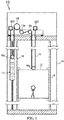
- FIG. 1 shows a schematic structural diagram of an elevator system according to an embodiment of the present invention.
- an elevator system 10 according to an embodiment of the present invention is concisely shown, and mainly includes a car 12, a traction wheel 14, sheaves 15 and 16, pull ropes 19 configured to lift the car 12, and a pull rope head fixing apparatus 200 which are uniformly arranged in a hoistway 11 of a building.
- the car 12 can travel vertically along a rail 18 arranged in the hoistway 11 or stop at a station.
- a corresponding tractor (not shown) is disposed corresponding to the traction wheel 14, and the tractor can drive the pull ropes 19 to lift the car 12.
- resistive sheaves 15a and 15b are included, and a return sheave 16a is also disposed corresponding to the car 12.
- the elevator system 10 further includes a counter-weight 13
- the sheave 15 further includes a return sheave 16b disposed corresponding to the counter-weight 13. It should be understood that the specific arrangements of the sheaves 15 and 16 are not limitative, and can be changed as a lifting method is changed.
- N there are N (N is greater than or equal to 2, e.g., equal to 3) pull ropes 19.
- the N pull ropes 19 are respectively provided with a pull rope head fixing apparatus 200 to fix rope heads 191 at two ends thereof, thus being more conducive to implementing the tension balanced state of the N pull ropes 19.
- the pull rope head fixing apparatus 200 can also be disposed merely at one end of the N pull ropes 19.
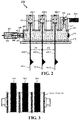
- FIG. 2 shows a schematic cross-sectional structural diagram of a pull rope head fixing apparatus according to an embodiment of the present invention.
- FIG. 3 schematically shows that pull ropes in the elevator system in the embodiment shown in FIG. 1 are wound on a sheave or a traction wheel.
- FIG. 4 shows a schematic structural diagram of a damping plate used in the pull rope head fixing apparatus shown in FIG. 2 . Illustrations are further made below with reference to FIG. 1 to FIG. 4 .
- N the number of the pull ropes 19 that are wound in parallel on the traction wheel 14, the resistive sheave 15, and the return sheave 16 may be larger.
- the traction wheel 14, the resistive sheave 15, and the return sheave 16 have large sizes in axial directions thereof, and it is also difficult to implement or keep equal tensions between the N pull ropes 19, e.g., it is difficult to keep the tension balanced state.
- the pull rope head fixing apparatus 200 in the embodiment shown in FIG. 2 is fixedly mounted in the elevator system 10.
- the pull rope head fixing apparatus 200 can be fixedly mounted in a machine room at the top of the hoistway 11.
- the pull rope head fixing apparatus 200 can be configured to simultaneously fix rope heads 191 of the N pull ropes 19 that are arranged in parallel.
- the pull rope head fixing apparatus 200 mainly includes a hydraulic cylinder body 210, N first hydraulic sub-cylinders 220 (i.e., 220-1, 220-2, and 220-3), and first pistons 221 each disposed corresponding to each first hydraulic sub-cylinder 220.
- a first piston 221-1 is disposed in a first hydraulic sub-cylinder 220-1 and can make a piston movement
- a first piston 221-2 is disposed in a first hydraulic sub-cylinder 220-2 and can make a piston movement
- a first piston 221-3 is disposed in a first hydraulic sub-cylinder 220-3 and can make a piston movement.
- the hydraulic cylinder body 210 can form a hydraulic cylinder 219 in a closed manner.
- the hydraulic cylinder body 210 can be fixedly mounted in a basically horizontal manner.
- An accommodation chamber of the hydraulic cylinder 219 accommodates hydraulic oil, and the hydraulic oil can be injected or discharged through an oil hole 211 disposed on the hydraulic cylinder body 210.
- the specific liquid type of the hydraulic oil is not limited.
- the N first hydraulic sub-cylinders 220 are arranged in parallel on the hydraulic cylinder body 210 and are communicated with the hydraulic cylinder 219. In other words, the N first hydraulic sub-cylinders 220 are communicated with the hydraulic cylinder 219, thus forming a through chamber in the hydraulic cylinder body 210.
- each first piston 221 in the through chamber can also transmit the tension from the pull rope 19 to the hydraulic oil in the through chamber.
- Each first piston 221 fixes a rope head 191 of a corresponding pull rope 19.
- the first piston 221-1 fixes a rope head 191-1 at one end of the pull rope 19-1
- the first piston 221-2 fixes a rope head 191-2 at one end of the pull rope 19-2
- the first piston 221-3 fixes a rope head 191-3 at one end of the pull rope 19-3.
- a piston rod 222 e.g., a piston rod 222-1 or 222-3 or 222-3 is disposed corresponding to each first piston 221.
- a first end of the piston rod 222 is connected to the corresponding first piston 221, and a second end of the piston rod 222 is connected to the rope head 191 of the corresponding pull rope 19.
- a clamp can be disposed at the second end of the piston rod 222 to fix the rope head 191. Therefore, when the tension of each pull role 19 is changed, the corresponding first piston 221 can move in the corresponding first hydraulic sub-cylinder 220.
- piston areas of the first hydraulic sub-cylinders 220-1, 220-2, and 220-3 can be preset. For example, piston areas of the first piston 221-1, the first piston 221-2, and the first piston 221-3 are set. If the tension ratio is equal to 1 (i.e., the tensions are equal), the piston areas of the first piston 221-1, the first piston 221-2, and the first piston 221-3 are constructed to be equal.
- the first hydraulic sub-cylinders 220-1, 220-2, and 220-3 are all cylindrical cylinders, and inner diameters of the first hydraulic sub-cylinders 220-1, 220-2, and 220-3 are all set to D. In other words, a ratio of the inner diameters is equal to 1. Therefore, the first hydraulic sub-cylinders 220-1, 220-2, and 220-3 can be constructed into sub-cylinders having the same structure.
- the first hydraulic sub-cylinders 220-1, 220-2, and 220-3 are all arranged vertically and protruded upward, and they can be arranged in parallel. Moreover, two adjacent first hydraulic sub-cylinders of the first hydraulic sub-cylinders 220-1, 220-2, and 220-3 have a basically equal center spacing P1. That is, the spacing between central axes of every two adjacent first hydraulic sub-cylinders is basically P1.
- the pull rope head fixing apparatus 200 in the embodiment shown in FIG. 2 can balance the hydraulic forces Ft between the N first pistons 221 in the through chamber, such that the tensions between the N pull ropes 19 are restored quickly or tend to be equal, that is, the tension balanced state is restored. Therefore, dynamic balance of the tensions between the N pull ropes 19 is implemented automatically in the operating process of the elevator system.
- the use of the pull rope head fixing apparatus 200 avoids the processes of manually detecting the tensions of the N pull ropes 19 and manually adjusting the tensions, thus greatly reducing maintenance operating state.
- the pull ropes 19 in the tension balanced state are also conducive to prolonging the service lives of the traction wheel 14, the resistive sheaves 15a and 15b, and the return sheaves 16a and 16b.
- the service lives of the multiple parallel pull ropes 19 are also more uniform.
- the pull rope head fixing apparatus 200 further includes: a second hydraulic sub-cylinder 240 arranged on the hydraulic cylinder body 210 and communicated with the hydraulic cylinder 219, a second piston 241 disposed corresponding to the second hydraulic sub-cylinder 240, and an elastic component 250. At least one end of the elastic component 250 receives a hydraulic force Fs transmitted from the hydraulic cylinder 219 by the second piston 241, and meanwhile applies a bounce from the elastic component 250 to the second piston 241. In other words, the hydraulic force Fs and the bounce form an acting force and a counter-acting force.
- the specific magnitude of the hydraulic force Fs depends on the intensity of pressure of the hydraulic oil in the through chamber in the hydraulic cylinder 210 with which the second hydraulic sub-cylinder 240 is communicated, and the magnitude of the intensity of pressure is affected by the magnitude of the tension between the pull ropes 19. For example, when the elevator system is braked to stop, the tension of each pull rope 19 may be increased instantly, each first piston 221 transmits the tension from the pull rope 19 to the hydraulic oil in the through chamber, and the intensity of pressure of the hydraulic oil is increased. Further, the hydraulic force Fs received by the second piston 241 in, for example, the increased pressure condition is also increased correspondingly, such that a force (basically equal to Fs) applied by the second piston 241 to the elastic component 250 is also increased.
- the elastic component 250 is compressed to generate a larger bounce to the second piston 241 until a balance is achieved. Therefore, the elastic component 250 can absorb energy from the pull ropes 19-1, 19-2, and 19-3, reduce the instant maximum tension of the pull ropes 19-1, 19-2, and 19-3, and/or alleviate the tension changes in the pull ropes 19-1, 19-2, and 19-3, thereby reducing the stretch length of the pull ropes 19-1, 19-2, and 19-3 and/or alleviating the stretch length changes in the pull ropes 19-1, 19-2, and 19-3, reducing the vibration amplitude of the car 12, and improving use experience of passengers.
- the elastic component 250 can be, for example, but is not limited to, an energy absorption component such as a spring.
- the specific magnitude of the hydraulic force Fs further depends on the area size of the second piston 241.
- the area of the second piston 241 can be determined by calculation according to the elastic coefficient of the elastic component 250, the area of the first piston 221, and the like.
- the second hydraulic sub-cylinder 240 can be configured into a cylindrical shape, and the area of the second piston 241 can be determined by determining an inner diameter d of the second hydraulic sub-cylinder 240 through calculation.
- the second hydraulic sub-cylinder 240 can be disposed to be protruded leftward horizontally.
- the pull rope head fixing apparatus 200 further includes a sleeve 251 fixedly disposed corresponding to the second hydraulic sub-cylinder 240.
- the elastic component 250 is disposed in the sleeve 251 and is located between a closed end of the sleeve 251 and the second piston 241.
- the length between an outer end of the second hydraulic sub-cylinder 240 and the closed end of the sleeve 251 is predetermined.
- the pull rope head fixing apparatus 200 further includes a damping plate 260 configured to alleviate changes in the hydraulic force Fs transmitted from the hydraulic cylinder 219 to the second piston 241.
- the damping plate 260 and the second piston 241 are arranged in the second hydraulic sub-cylinder 240 basically in parallel.
- One or more circulation holes 261 can be disposed on the damping plate 260.
- An area proportion of all the circulation holes 261 on the damping plate 260 depends on the degree of alleviating the changes in the hydraulic force Fs. A higher proportion leads to a lower alleviation degree, and a lower proportion leads to a higher alleviation degree.
- the multiple circulation holes 261 are dispersed on the damping plate 260 basically uniformly.
- the hydraulic force Fs received by the second piston 241 is also increased correspondingly in, for example, the condition of an increased intensity of pressure, such that the second piston 241 moves leftward.
- the damping plate 260 can reduce the speed of the hydraulic oil being injected into the space between the damping plate 260 and the second piston 241 through the circulation holes 261. Therefore, the increase of the hydraulic force Fs transmitted to the second piston 241 is slowed down.
- the damping plate 260 slows down the reduction of the hydraulic force Fs transmitted to the second piston 241.
- the damping plate 260 can alleviate the changes in the hydraulic force Fs transmitted from the hydraulic cylinder 219 to the second piston 241, further reduce the changes in the stretch lengths of the pull ropes 19-1, 19-2, and 19-3, reduce the vibration amplitude of the car 12, and further improve the experience of passengers.
- the pull rope head fixing apparatus 200 further includes a tension detection component 232.
- the tension detection component 232 can, for example, indirectly detect the magnitude of the tension of the pull rope 19 in real time.
- the tension value can be sent to a control component of the elevator system 10 to be used for, e.g., calculating a pre-torque or controlling a tractor.
- the tensions of the N pull ropes 19 keep in a predetermined proportional relationship, e.g., keep being basically the same; therefore, the magnitudes of the tensions detected by the tension detection component 232 also reflect the tension values of the N pull ropes 19.
- a third hydraulic sub-cylinder 230 in communication with the hydraulic cylinder 219 can be arranged on the hydraulic cylinder body 210, and a third piston 231 disposed corresponding to the third hydraulic sub-cylinder 230 is further arranged.
- the tension detection component 232 is disposed on a piston rod of the third piston 231.
- the third piston 231 receives a hydraulic force transmitted from the hydraulic oil in the through chamber, and transmits the hydraulic force to the piston rod. The hydraulic force is then detected by the tension detection component 232.
- the hydraulic force Ft can be calculated based on the hydraulic force, such that the magnitudes of the tensions of the N pull ropes 19 can be obtained by calculation.
- the magnitudes of the tensions of the N pull ropes 19 can be detected conveniently; this is obviously different from the prior art in which the magnitudes of the tensions of the multiple pull ropes 19 may be different and need to be detected manually, which is very time consuming and labor consuming.
- the tension detection component 232 can have a display apparatus 2321 configured to display the magnitude of the tension detected, thus facilitating an operator to read the magnitude of the tension.
- the pull rope 19 used in the above embodiments of the present invention can be, for example, a flat steel belt formed by wrapping multiple steel wires with polyurethane, or can be a flat carbon fiber belt.
- the pull rope can also be other various types of flat ropes with the width of the cross section greater than the thickness of the cross section, or even can be various flat ropes developed subsequently after the present application.
- a major reinforcing component for carrying is a steel wire or a steel rope, and can further include, for example, a wrap layer using polyurethane and the like, or even can further include other reinforcing fibers or the like arranged in a longitudinal direction of the rope to serve as assistant reinforcing components.
- a major reinforcing component for carrying is a carbon fiber or other reinforcing fibers having performances similar to that of the carbon fibers.
- the flat carbon fiber belt can, but is not limited to, include a substrate material configured to distribute or fix carbon fibers, and the carbon fibers are fixedly distributed in the substrate material to form the major carrying component of the flat fiber belt.
- the flat carbon fiber belt can further include other types of reinforcing fibers or the like arranged in a longitudinal direction of the rope to serve as assistant reinforcing components.
Landscapes
- Engineering & Computer Science (AREA)
- Automation & Control Theory (AREA)
- Structural Engineering (AREA)
- Lift-Guide Devices, And Elevator Ropes And Cables (AREA)
Abstract
Description
- The present invention belongs to the technical field of elevators, and relates to a pull rope head fixing apparatus that can automatically balance the tensions of multiple pull ropes and an elevator system using the same.
- A pull rope is a common component in an elevator system, and is also a key component for the operation of the elevator system. The pull rope, when being driven by a tractor of the elevator system, can be used for lifting a car or the like.
- At present, multiple pull ropes are generally used to lift a car simultaneously, especially when the pull ropes are flat ropes (e.g., steel belts) with the width of the cross section greater than the thickness thereof. As such, the multiple pull ropes are wound on, for example, a traction wheel and/or a sheave in parallel and may have different magnitudes of tensions respectively.
- According to one aspect of the present invention, a pull rope head fixing apparatus for an elevator system is provided, which is configured to simultaneously fix rope heads of N pull ropes that are arranged in parallel, N being an integer greater than or equal to 2. The pull rope head fixing apparatus includes:
- a hydraulic cylinder body configured to form a hydraulic cylinder;
- N first hydraulic sub-cylinders arranged in parallel on the hydraulic cylinder body and communicated with the hydraulic cylinder; and
- first pistons each disposed corresponding to each of the first hydraulic sub-cylinders, wherein each of the first pistons is configured to fix a rope head of a corresponding pull rope and is movable in a corresponding first hydraulic sub-cylinder when the tension of the pull rope changes.
- According to another aspect of the present invention, an elevator system is provided, including a car, a traction wheel, a sheave, and pull ropes configured to lift the car, and further including the pull rope head fixing apparatus, wherein the N pull ropes are wound on the traction wheel and the sheave in parallel, and N rope heads of at least one end of the N pull ropes are fixed to the pull rope head fixing apparatus.
- The above features and operations of the present invention will become more apparent according to the following descriptions and accompanying drawings.
- The above and other objectives and advantages of the present invention will be more complete and clearer from the following detailed descriptions with reference to the accompanying drawings, wherein identical or similar elements are represented by using identical reference numerals.
-
FIG. 1 is a schematic structural diagram of an elevator system according to an embodiment of the present invention. -
FIG. 2 is a schematic cross-sectional structural diagram of a pull rope head fixing apparatus according to an embodiment of the present invention. -
FIG. 3 schematically shows that pull ropes in the elevator system in the embodiment shown inFIG. 1 are wound on a sheave or traction wheel. -
FIG. 4 is a schematic structural diagram of a damping plate used in the pull rope head fixing apparatus in the embodiment shown inFIG. 2 . - Some of multiple possible embodiments of the present invention are introduced in the following to provide basic understanding of the present invention, and it is not intended to determine key or crucial elements of the present invention or limit the scope to be protected. It is easily understood that those of ordinary skill in the art can propose other replaceable implementation manners according to the technical solution of the present invention without changing the essential spirit of the present invention. Therefore, the following specific implementation manners and the accompanying drawings are merely exemplary illustrations on the technical solutions of the present invention and should not be considered as all of the present invention or considered as definitions or limitations to the technical solution of the present invention.
- In this text, a "tension balanced state" of multiple pull ropes refers to that tensions of the multiple pull ropes, in a static state, basically keep a predetermined proportional relationship. The tensions of the multiple pull ropes are kept to be basically the same in a tension balanced state in most cases; however, the "tension balanced state" of the present invention is not limited to this case. For example, the predetermined proportion relationship can be adjusted and set according to special requirements.
- The applicant also noticed that, for an elevator system that uses multiple pull ropes to lift a car, performance differences such as flexibilities of the multiple pull ropes or other reasons may easily result in that the tension is not kept balance between the multiple pull ropes (e.g., not kept equal), that is, the multiple pull ropes are in a tension unbalanced state. The unbalanced tension may easily cause a traction wheel and/or sheave on which the pull ropes are wound to be worn, and may also easily cause the pull ropes themselves to be worn, thus reducing the service lives of these components, and even affecting the operating quality (e.g., large noise and increased vibration) of the elevator system and/or reducing the safety performance of the system. Therefore, the tensions between the multiple pull ropes need to be adjusted manually to achieve a tension balanced state. The process is very time consuming and labor consuming. Moreover, as the elevator system operates, it is difficult to keep the tension balanced sate, and multiple adjustments are required continuously, thus resulting in a large maintenance workload.
- Particular, when the pull rope is a flat pull rope (e.g., a flat steel belt or a flat fiber belt) with the width of the cross section greater than the thickness thereof, it is well-known by those skilled in the art that the flat pull rope has poorer rigidity but better flexibility than a round rope; therefore, on one hand, the flat pull rope is easily stretched to be longer, thus being especially easy to cause unbalanced tensions between multiple flat pull ropes; on the other hand, more (e.g., 7 or more) flat pull ropes arranged in parallel are needed in the same case, and it is more difficult to achieve the tension balance between the more flat pull ropes. In other words, the above problem is especially severe in an elevator system applying flat pull ropes.
- Therefore, a pull rope head fixing apparatus and an elevator system in the following embodiments of the present invention are illustrated by taking the pull rope used being a flat pull rope as an example.
-
FIG. 1 shows a schematic structural diagram of an elevator system according to an embodiment of the present invention. As shown inFIG. 1 , anelevator system 10 according to an embodiment of the present invention is concisely shown, and mainly includes acar 12, atraction wheel 14,sheaves pull ropes 19 configured to lift thecar 12, and a pull ropehead fixing apparatus 200 which are uniformly arranged in ahoistway 11 of a building. Thecar 12 can travel vertically along arail 18 arranged in thehoistway 11 or stop at a station. A corresponding tractor (not shown) is disposed corresponding to thetraction wheel 14, and the tractor can drive thepull ropes 19 to lift thecar 12. - In an embodiment, there may be multiple sheaves. For example,
resistive sheaves return sheave 16a is also disposed corresponding to thecar 12. When a counter-weight is used, theelevator system 10 further includes acounter-weight 13, and thesheave 15 further includes areturn sheave 16b disposed corresponding to thecounter-weight 13. It should be understood that the specific arrangements of thesheaves - In an embodiment, there are N (N is greater than or equal to 2, e.g., equal to 3)
pull ropes 19. TheN pull ropes 19 are respectively provided with a pull ropehead fixing apparatus 200 to fix rope heads 191 at two ends thereof, thus being more conducive to implementing the tension balanced state of theN pull ropes 19. In another alternative embodiment, the pull ropehead fixing apparatus 200 can also be disposed merely at one end of theN pull ropes 19. -
FIG. 2 shows a schematic cross-sectional structural diagram of a pull rope head fixing apparatus according to an embodiment of the present invention.FIG. 3 schematically shows that pull ropes in the elevator system in the embodiment shown inFIG. 1 are wound on a sheave or a traction wheel.FIG. 4 shows a schematic structural diagram of a damping plate used in the pull rope head fixing apparatus shown inFIG. 2 . Illustrations are further made below with reference toFIG. 1 to FIG. 4 . - For simplicity,
FIG. 2 and FIG. 3 merely show threepull ropes 19, i.e., N=3. However, as shown inFIG. 1 andFIG. 3 , when the pull ropes 19 use flat pull ropes, the number of thepull ropes 19 that are wound in parallel on thetraction wheel 14, theresistive sheave 15, and thereturn sheave 16 may be larger. As such, thetraction wheel 14, theresistive sheave 15, and thereturn sheave 16 have large sizes in axial directions thereof, and it is also difficult to implement or keep equal tensions between theN pull ropes 19, e.g., it is difficult to keep the tension balanced state. - Still referring to
FIG. 1 andFIG. 2 , the pull ropehead fixing apparatus 200 in the embodiment shown inFIG. 2 is fixedly mounted in theelevator system 10. Specifically, the pull ropehead fixing apparatus 200 can be fixedly mounted in a machine room at the top of thehoistway 11. The pull ropehead fixing apparatus 200 can be configured to simultaneously fix rope heads 191 of theN pull ropes 19 that are arranged in parallel. Specifically, the pull ropehead fixing apparatus 200 mainly includes ahydraulic cylinder body 210, N first hydraulic sub-cylinders 220 (i.e., 220-1, 220-2, and 220-3), and first pistons 221 each disposed corresponding to each first hydraulic sub-cylinder 220. For example, a first piston 221-1 is disposed in a first hydraulic sub-cylinder 220-1 and can make a piston movement, a first piston 221-2 is disposed in a first hydraulic sub-cylinder 220-2 and can make a piston movement, and a first piston 221-3 is disposed in a first hydraulic sub-cylinder 220-3 and can make a piston movement. - Specifically, the
hydraulic cylinder body 210 can form ahydraulic cylinder 219 in a closed manner. Specifically, thehydraulic cylinder body 210 can be fixedly mounted in a basically horizontal manner. An accommodation chamber of thehydraulic cylinder 219 accommodates hydraulic oil, and the hydraulic oil can be injected or discharged through anoil hole 211 disposed on thehydraulic cylinder body 210. The specific liquid type of the hydraulic oil is not limited. Still referring toFIG. 2 , the N first hydraulic sub-cylinders 220 are arranged in parallel on thehydraulic cylinder body 210 and are communicated with thehydraulic cylinder 219. In other words, the N first hydraulic sub-cylinders 220 are communicated with thehydraulic cylinder 219, thus forming a through chamber in thehydraulic cylinder body 210. By using hydraulic attributes, a hydraulic force Ft can be transmitted to each first piston 221 in the through chamber simultaneously, and the magnitude of the hydraulic force Ft is related to the area of the first piston 221. Definitely, each first piston 221 can also transmit the tension from thepull rope 19 to the hydraulic oil in the through chamber. - Each first piston 221 fixes a rope head 191 of a
corresponding pull rope 19. For example, the first piston 221-1 fixes a rope head 191-1 at one end of the pull rope 19-1, the first piston 221-2 fixes a rope head 191-2 at one end of the pull rope 19-2, and the first piston 221-3 fixes a rope head 191-3 at one end of the pull rope 19-3. In an embodiment, a piston rod 222 (e.g., a piston rod 222-1 or 222-3 or 222-3) is disposed corresponding to each first piston 221. A first end of the piston rod 222 is connected to the corresponding first piston 221, and a second end of the piston rod 222 is connected to the rope head 191 of thecorresponding pull rope 19. Specifically, for example, a clamp can be disposed at the second end of the piston rod 222 to fix the rope head 191. Therefore, when the tension of each pullrole 19 is changed, the corresponding first piston 221 can move in the corresponding first hydraulic sub-cylinder 220. - According to a tension ratio of the pull ropes 19-1, 19-2, and 19-3 in the tension balanced state, piston areas of the first hydraulic sub-cylinders 220-1, 220-2, and 220-3 can be preset. For example, piston areas of the first piston 221-1, the first piston 221-2, and the first piston 221-3 are set. If the tension ratio is equal to 1 (i.e., the tensions are equal), the piston areas of the first piston 221-1, the first piston 221-2, and the first piston 221-3 are constructed to be equal. Specifically, for example, the first hydraulic sub-cylinders 220-1, 220-2, and 220-3 are all cylindrical cylinders, and inner diameters of the first hydraulic sub-cylinders 220-1, 220-2, and 220-3 are all set to D. In other words, a ratio of the inner diameters is equal to 1. Therefore, the first hydraulic sub-cylinders 220-1, 220-2, and 220-3 can be constructed into sub-cylinders having the same structure.
- In an embodiment, still referring to
FIG. 2 , the first hydraulic sub-cylinders 220-1, 220-2, and 220-3 are all arranged vertically and protruded upward, and they can be arranged in parallel. Moreover, two adjacent first hydraulic sub-cylinders of the first hydraulic sub-cylinders 220-1, 220-2, and 220-3 have a basically equal center spacing P1. That is, the spacing between central axes of every two adjacent first hydraulic sub-cylinders is basically P1. - Therefore, even if the tensions between the N pull
ropes 19 are unbalanced, e.g., unequal, at a certain instant, the pull ropehead fixing apparatus 200 in the embodiment shown inFIG. 2 can balance the hydraulic forces Ft between the N first pistons 221 in the through chamber, such that the tensions between the N pullropes 19 are restored quickly or tend to be equal, that is, the tension balanced state is restored. Therefore, dynamic balance of the tensions between the N pullropes 19 is implemented automatically in the operating process of the elevator system. The use of the pull ropehead fixing apparatus 200 avoids the processes of manually detecting the tensions of the N pullropes 19 and manually adjusting the tensions, thus greatly reducing maintenance operating state. Meanwhile, thepull ropes 19 in the tension balanced state are also conducive to prolonging the service lives of thetraction wheel 14, theresistive sheaves parallel pull ropes 19 are also more uniform. - Still referring to
FIG. 2 , in an embodiment, the pull ropehead fixing apparatus 200 further includes: a secondhydraulic sub-cylinder 240 arranged on thehydraulic cylinder body 210 and communicated with thehydraulic cylinder 219, asecond piston 241 disposed corresponding to the secondhydraulic sub-cylinder 240, and anelastic component 250. At least one end of theelastic component 250 receives a hydraulic force Fs transmitted from thehydraulic cylinder 219 by thesecond piston 241, and meanwhile applies a bounce from theelastic component 250 to thesecond piston 241. In other words, the hydraulic force Fs and the bounce form an acting force and a counter-acting force. - The specific magnitude of the hydraulic force Fs depends on the intensity of pressure of the hydraulic oil in the through chamber in the
hydraulic cylinder 210 with which the secondhydraulic sub-cylinder 240 is communicated, and the magnitude of the intensity of pressure is affected by the magnitude of the tension between thepull ropes 19. For example, when the elevator system is braked to stop, the tension of eachpull rope 19 may be increased instantly, each first piston 221 transmits the tension from thepull rope 19 to the hydraulic oil in the through chamber, and the intensity of pressure of the hydraulic oil is increased. Further, the hydraulic force Fs received by thesecond piston 241 in, for example, the increased pressure condition is also increased correspondingly, such that a force (basically equal to Fs) applied by thesecond piston 241 to theelastic component 250 is also increased. Meanwhile, theelastic component 250 is compressed to generate a larger bounce to thesecond piston 241 until a balance is achieved. Therefore, theelastic component 250 can absorb energy from the pull ropes 19-1, 19-2, and 19-3, reduce the instant maximum tension of the pull ropes 19-1, 19-2, and 19-3, and/or alleviate the tension changes in the pull ropes 19-1, 19-2, and 19-3, thereby reducing the stretch length of the pull ropes 19-1, 19-2, and 19-3 and/or alleviating the stretch length changes in the pull ropes 19-1, 19-2, and 19-3, reducing the vibration amplitude of thecar 12, and improving use experience of passengers. It will be understood that theelastic component 250 can be, for example, but is not limited to, an energy absorption component such as a spring. - The specific magnitude of the hydraulic force Fs further depends on the area size of the
second piston 241. The area of thesecond piston 241 can be determined by calculation according to the elastic coefficient of theelastic component 250, the area of the first piston 221, and the like. Specifically, for example, the secondhydraulic sub-cylinder 240 can be configured into a cylindrical shape, and the area of thesecond piston 241 can be determined by determining an inner diameter d of the secondhydraulic sub-cylinder 240 through calculation. For example, the secondhydraulic sub-cylinder 240 can be disposed to be protruded leftward horizontally. - Still referring to
FIG. 2 , in an embodiment, the pull ropehead fixing apparatus 200 further includes asleeve 251 fixedly disposed corresponding to the secondhydraulic sub-cylinder 240. Theelastic component 250 is disposed in thesleeve 251 and is located between a closed end of thesleeve 251 and thesecond piston 241. The length between an outer end of the secondhydraulic sub-cylinder 240 and the closed end of thesleeve 251 is predetermined. - Still referring to
FIG. 2 andFIG. 4 , in an embodiment, the pull ropehead fixing apparatus 200 further includes a dampingplate 260 configured to alleviate changes in the hydraulic force Fs transmitted from thehydraulic cylinder 219 to thesecond piston 241. The dampingplate 260 and thesecond piston 241 are arranged in the secondhydraulic sub-cylinder 240 basically in parallel. One ormore circulation holes 261 can be disposed on the dampingplate 260. An area proportion of all the circulation holes 261 on the dampingplate 260 depends on the degree of alleviating the changes in the hydraulic force Fs. A higher proportion leads to a lower alleviation degree, and a lower proportion leads to a higher alleviation degree. In an embodiment, as shown inFIG. 4 , themultiple circulation holes 261 are dispersed on the dampingplate 260 basically uniformly. - In a process that the intensity of pressure of the hydraulic oil in the
hydraulic cylinder 219 is increased, the hydraulic force Fs received by thesecond piston 241 is also increased correspondingly in, for example, the condition of an increased intensity of pressure, such that thesecond piston 241 moves leftward. At this instant, the dampingplate 260 can reduce the speed of the hydraulic oil being injected into the space between the dampingplate 260 and thesecond piston 241 through the circulation holes 261. Therefore, the increase of the hydraulic force Fs transmitted to thesecond piston 241 is slowed down. Similarly, in a process that the intensity of pressure of the hydraulic oil in thehydraulic cylinder 219 is reduced, the dampingplate 260 slows down the reduction of the hydraulic force Fs transmitted to thesecond piston 241. Therefore, the dampingplate 260 can alleviate the changes in the hydraulic force Fs transmitted from thehydraulic cylinder 219 to thesecond piston 241, further reduce the changes in the stretch lengths of the pull ropes 19-1, 19-2, and 19-3, reduce the vibration amplitude of thecar 12, and further improve the experience of passengers. - In an embodiment, as shown in
FIG. 2 , the pull ropehead fixing apparatus 200 further includes atension detection component 232. Thetension detection component 232 can, for example, indirectly detect the magnitude of the tension of thepull rope 19 in real time. The tension value can be sent to a control component of theelevator system 10 to be used for, e.g., calculating a pre-torque or controlling a tractor. It should be understood that the tensions of the N pullropes 19 keep in a predetermined proportional relationship, e.g., keep being basically the same; therefore, the magnitudes of the tensions detected by thetension detection component 232 also reflect the tension values of theN pull ropes 19. - Specifically, corresponding to the
tension detection component 232, a thirdhydraulic sub-cylinder 230 in communication with thehydraulic cylinder 219 can be arranged on thehydraulic cylinder body 210, and athird piston 231 disposed corresponding to the thirdhydraulic sub-cylinder 230 is further arranged. Thetension detection component 232 is disposed on a piston rod of thethird piston 231. During detection, thethird piston 231 receives a hydraulic force transmitted from the hydraulic oil in the through chamber, and transmits the hydraulic force to the piston rod. The hydraulic force is then detected by thetension detection component 232. When the piston area of thethird piston 231 is known, the hydraulic force Ft can be calculated based on the hydraulic force, such that the magnitudes of the tensions of the N pullropes 19 can be obtained by calculation. Therefore, in the pull ropehead fixing apparatus 200 according to the embodiment of the present invention, the magnitudes of the tensions of the N pullropes 19 can be detected conveniently; this is obviously different from the prior art in which the magnitudes of the tensions of themultiple pull ropes 19 may be different and need to be detected manually, which is very time consuming and labor consuming. - In an embodiment, as shown in
FIG. 2 , thetension detection component 232 can have adisplay apparatus 2321 configured to display the magnitude of the tension detected, thus facilitating an operator to read the magnitude of the tension. - It should be noted that the
pull rope 19 used in the above embodiments of the present invention can be, for example, a flat steel belt formed by wrapping multiple steel wires with polyurethane, or can be a flat carbon fiber belt. However, the pull rope can also be other various types of flat ropes with the width of the cross section greater than the thickness of the cross section, or even can be various flat ropes developed subsequently after the present application. As for a flat steel belt, a major reinforcing component for carrying is a steel wire or a steel rope, and can further include, for example, a wrap layer using polyurethane and the like, or even can further include other reinforcing fibers or the like arranged in a longitudinal direction of the rope to serve as assistant reinforcing components. As for a flat carbon fiber belt, a major reinforcing component for carrying is a carbon fiber or other reinforcing fibers having performances similar to that of the carbon fibers. Definitely, it should be understood that the flat carbon fiber belt can, but is not limited to, include a substrate material configured to distribute or fix carbon fibers, and the carbon fibers are fixedly distributed in the substrate material to form the major carrying component of the flat fiber belt. It should be further understood that, in addition to assistant fibers, the flat carbon fiber belt can further include other types of reinforcing fibers or the like arranged in a longitudinal direction of the rope to serve as assistant reinforcing components. - The above examples mainly illustrate the pull rope head fixing apparatus and the elevator system using the same according to the present invention. Merely some implementation manners of the present invention are described; however, those of ordinary skill in the art should understand that the present invention can be implemented in many other forms without departing from the substance and scope of the present invention. Therefore, the presented examples and implementation manners are considered as illustrative rather than limitative. The present invention can cover various modifications and replacements without departing from the spirit and scope of the present invention defined by the appended claims.
Claims (15)
- A pull rope head fixing apparatus for an elevator system, configured to simultaneously fix rope heads of N pull ropes that are arranged in parallel, N being an integer greater than or equal to 2, the pull rope head fixing apparatus comprising:a hydraulic cylinder body configured to form a hydraulic cylinder;N first hydraulic sub-cylinders arranged in parallel on the hydraulic cylinder body and communicated with the hydraulic cylinder; andfirst pistons each disposed corresponding to each of the first hydraulic sub-cylinders, wherein each of the first pistons is configured to fix a rope head of a corresponding pull rope and is movable in a corresponding first hydraulic sub-cylinder when the tension of the pull rope changes.
- The pull rope head fixing apparatus according to Claim 1, further comprising:a second hydraulic sub-cylinder arranged on the hydraulic cylinder body and communicated with the hydraulic cylinder;a second piston disposed corresponding to the second hydraulic sub-cylinder; andan elastic component, at least one end of the elastic component receiving a hydraulic force of the hydraulic cylinder transmitted from the second piston while applying a bounce to the second piston.
- The pull rope head fixing apparatus according to Claim 2, further comprising a sleeve disposed fixedly corresponding to the second hydraulic sub-cylinder, wherein the elastic component is disposed in the sleeve and located between a closed end of the sleeve and the second piston.
- The pull rope head fixing apparatus according to Claim 2 or 3, further comprising:a damping plate configured to alleviate changes in the hydraulic force transmitted to the second piston.
- The pull rope head fixing apparatus according to Claim 4, wherein the damping plate and the second piston are arranged basically in parallel in the second hydraulic sub-cylinder.
- The pull rope head fixing apparatus according to Claim 4 or 5, wherein one or more circulation holes are disposed on the damping plate; and preferably
wherein the multiple circulation holes are dispersed basically uniformly on the damping plate. - The pull rope head fixing apparatus according to any preceding Claim, wherein a piston area of the N first hydraulic sub-cylinders is determined according to a tension ratio of the N pull ropes in a tension balanced state.
- The pull rope head fixing apparatus according to Claim 7, wherein the N first hydraulic sub-cylinders are all cylindrical, and a ratio of inner diameters of the N first hydraulic sub-cylinders is equal to the tension ratio.
- The pull rope head fixing apparatus according to Claim 7 or 8, wherein the tension ratio is equal to 1.
- The pull rope head fixing apparatus according to any preceding Claim, wherein a piston rod is disposed corresponding to each of the first pistons, a first end of the piston rod is connected to the corresponding first piston, and a second end of the piston rod is connected to a rope head of the corresponding pull rope.
- The pull rope head fixing apparatus according to any preceding Claim, wherein the N first hydraulic sub-cylinders are arranged in parallel and protruded upward vertically, and a basically equal center spacing is provided between two adjacent first hydraulic sub-cylinders of the N first hydraulic sub-cylinders.
- The pull rope head fixing apparatus according to any preceding Claim, further comprising a tension detection component; and preferably
wherein the tension detection component has a display apparatus configured to display the magnitude of a tension detected. - The pull rope head fixing apparatus according to Claim 12, further comprising:a third hydraulic sub-cylinder arranged on the hydraulic cylinder body and communicated with the hydraulic cylinder; anda third piston disposed corresponding to the third hydraulic sub-cylinder,wherein the tension detection component is disposed on a piston rod of the third piston.
- The pull rope head fixing apparatus according to any of Claims 1 to 13, wherein the width of a cross section of the pull rope is greater than the thickness of the cross section; and preferably wherein the pull rope is a flat steel belt or a flat fiber belt.
- An elevator system, comprising a car, a traction wheel, a sheave, and a pull rope configured to lift the car, and further comprising the pull rope head fixing apparatus according to any of Claims 1 to 14, wherein the N pull ropes are wound on the traction wheel and the sheave in parallel, and N rope heads of at least one end of the N pull ropes are fixed to the pull rope head fixing apparatus; and optionally:wherein the N pull ropes dynamically keep tension balance in an operating process of the elevator system; and/orwherein the pull rope head fixing apparatus is disposed respectively at two ends of the N pull ropes; and/orfurther comprising a counter-weight, wherein the pull ropes are further configured to lift the counter-weight.
Applications Claiming Priority (1)
| Application Number | Priority Date | Filing Date | Title |
|---|---|---|---|
| CN201710982829.XA CN109693990B (en) | 2017-10-20 | 2017-10-20 | Lifting rope end fixing device and elevator system using same |
Publications (2)
| Publication Number | Publication Date |
|---|---|
| EP3495305A1 true EP3495305A1 (en) | 2019-06-12 |
| EP3495305B1 EP3495305B1 (en) | 2021-12-01 |
Family
ID=63965176
Family Applications (1)
| Application Number | Title | Priority Date | Filing Date |
|---|---|---|---|
| EP18201609.7A Active EP3495305B1 (en) | 2017-10-20 | 2018-10-19 | End-fastening apparatus for lifting rope and elevator system using thereof |
Country Status (3)
| Country | Link |
|---|---|
| US (1) | US11124387B2 (en) |
| EP (1) | EP3495305B1 (en) |
| CN (1) | CN109693990B (en) |
Families Citing this family (3)
| Publication number | Priority date | Publication date | Assignee | Title |
|---|---|---|---|---|
| US10889470B2 (en) * | 2017-12-08 | 2021-01-12 | Thyssenkrupp Elevator Corporation | Automatic rope tension equalizer system and method |
| EP3689805B1 (en) * | 2019-01-29 | 2022-01-05 | Prysmian S.p.A. | Elevator system |
| CN115594059A (en) * | 2022-12-01 | 2023-01-13 | 启东市三联建筑机械有限公司(Cn) | Stress adjusting mechanism for installing steel cable of mine hoist |
Citations (2)
| Publication number | Priority date | Publication date | Assignee | Title |
|---|---|---|---|---|
| JPS5323448A (en) * | 1976-08-16 | 1978-03-03 | Mitsubishi Electric Corp | Device for holding strings |
| WO2011014165A1 (en) * | 2009-07-29 | 2011-02-03 | Otis Elelvator Company | Rope sway mitigation via rope tension adjustment |
Family Cites Families (24)
| Publication number | Priority date | Publication date | Assignee | Title |
|---|---|---|---|---|
| GB191102822A (en) * | 1911-02-03 | 1912-02-05 | Thomas Greenhalgh | Improvements in or relating to Safety Devices for Lifts, Cages and the like. |
| US1516727A (en) * | 1923-08-21 | 1924-11-25 | American Mach & Foundry | Pressure-chamber and plunger construction |
| US3052320A (en) | 1959-07-01 | 1962-09-04 | Prep Ind Combustibles | Process and apparatus for adjusting the length and/or tension of a rope |
| GB919768A (en) | 1960-03-22 | 1963-02-27 | Reliance Rope Attachment Compa | Improvements in or relating to rope tensioning devices |
| DE3540266C1 (en) | 1985-11-13 | 1986-12-18 | Heuer-Hammer GmbH & Co KG, 5860 Iserlohn | Overload protection |
| DE3720488A1 (en) * | 1987-06-20 | 1988-02-25 | Klaus Schulz | Hydraulic rope-tensioning device for lifts with driving pulleys and rope suspension |
| CN1019786B (en) * | 1990-03-17 | 1992-12-30 | 铁法矿务局 | Automatic wire tension balancing device for multiple wire hoist |
| CN2144177Y (en) * | 1992-12-02 | 1993-10-20 | 邵忠明 | Force isostatic adjustment device for multiple steel cables |
| CN1044998C (en) * | 1996-09-27 | 1999-09-08 | 中国矿业大学 | Automatic tension balancing and hanging device for steel wire rope |
| US6223862B1 (en) | 1999-06-17 | 2001-05-01 | Michael Barnes | Elevator cable tensioning device and method |
| SG94783A1 (en) * | 2000-03-31 | 2003-03-18 | Inventio Ag | Tensioning device for at least one trailing rope of an elevator installation |
| KR20010088888A (en) | 2001-02-05 | 2001-09-29 | 최정두 | Rope tension equalizer of rope type elevator |
| US7946390B2 (en) * | 2003-05-30 | 2011-05-24 | Otis Elevator Company | Tie-down compensation for an elevator system |
| FI118335B (en) | 2004-07-30 | 2007-10-15 | Kone Corp | Elevator |
| FI20060627A7 (en) | 2006-06-28 | 2007-12-29 | Kone Corp | Arrangement in a counterweightless elevator |
| DE102008032881B3 (en) | 2008-07-14 | 2009-11-12 | Dywidag-Systems International Gmbh | Apparatus and method for controlling a tensioning press when tensioning a tendon |
| FI121921B (en) | 2009-11-05 | 2011-06-15 | Kone Corp | Method and apparatus for reducing the oscillation of the ropes to an elevator |
| KR101023580B1 (en) | 2010-07-15 | 2011-03-21 | 전병수 | Elevator Wire Rope Tension Automatic Equalizer |
| CN102020161B (en) | 2010-12-03 | 2012-08-22 | 中国矿业大学 | Connecting device of hauling rope of elevator for mines and detection method thereof |
| CN102085993B (en) | 2010-12-03 | 2013-06-26 | 中国矿业大学 | Device and method for automatically adjusting tension force of flexible guide rail of mine elevator |
| WO2013182209A1 (en) | 2012-06-05 | 2013-12-12 | Soliman Mohamed Abdel Hameed Abdel Alleem Mohamed | Advanced roped hydraulic elevator with and without counterweight for all heights and speeds. |
| CN103538989B (en) * | 2013-09-29 | 2016-08-10 | 中国矿业大学 | Multi-rope hoist wire rope tension balance displacement adjustment state monitoring method and device |
| EP3070043A1 (en) | 2015-03-18 | 2016-09-21 | Inventio AG | Clamping device in elevator installations |
| WO2017046889A1 (en) | 2015-09-16 | 2017-03-23 | 三菱電機株式会社 | Elevator |
-
2017
- 2017-10-20 CN CN201710982829.XA patent/CN109693990B/en active Active
-
2018
- 2018-10-18 US US16/164,505 patent/US11124387B2/en active Active
- 2018-10-19 EP EP18201609.7A patent/EP3495305B1/en active Active
Patent Citations (2)
| Publication number | Priority date | Publication date | Assignee | Title |
|---|---|---|---|---|
| JPS5323448A (en) * | 1976-08-16 | 1978-03-03 | Mitsubishi Electric Corp | Device for holding strings |
| WO2011014165A1 (en) * | 2009-07-29 | 2011-02-03 | Otis Elelvator Company | Rope sway mitigation via rope tension adjustment |
Also Published As
| Publication number | Publication date |
|---|---|
| US11124387B2 (en) | 2021-09-21 |
| EP3495305B1 (en) | 2021-12-01 |
| CN109693990B (en) | 2021-06-08 |
| US20190119070A1 (en) | 2019-04-25 |
| CN109693990A (en) | 2019-04-30 |
Similar Documents
| Publication | Publication Date | Title |
|---|---|---|
| EP3495305B1 (en) | End-fastening apparatus for lifting rope and elevator system using thereof | |
| JP5478247B2 (en) | Elevator mechanism without counterweight | |
| HK1222162A1 (en) | Elevator | |
| JPH0761745A (en) | Hoist type elevator | |
| US4230205A (en) | Elevator system | |
| TW200936483A (en) | Lift with two lift cabins | |
| CN201809059U (en) | Crane pulley block mechanism and crane comprising same | |
| US12180040B2 (en) | Belt with layered load bearing elements | |
| KR20180048784A (en) | Elevator rope and manufacturing method thereof | |
| CN107651553A (en) | A kind of crane | |
| US6431321B2 (en) | Tensioning device for at least one trailing rope of an elevator installation | |
| CN1054952A (en) | Automatic wire tension balancing device for multiple wire hoist | |
| KR102657801B1 (en) | Elevator system suspension member | |
| AU2015258338B2 (en) | Arrangement and method | |
| US1725402A (en) | Elevator-cable equalizer | |
| DE10312847A1 (en) | Doppelseilbalancer | |
| EP3738915A1 (en) | Koepe hoist | |
| CN112758785A (en) | Elevator rope head device | |
| CN111924679A (en) | High-traction-ratio winding type elevator traction system | |
| JP6403889B2 (en) | Elevator equipment | |
| FI128652B (en) | Trolley for wire rope hoist | |
| CN109368444B (en) | Steel wire rope tension balancing device of winding combined type multi-rope traction system | |
| KR101861139B1 (en) | Rope tension control equipment for elevator | |
| CN105800432A (en) | Elevator | |
| JP2004203601A (en) | Traction increasing device for elevator rope |
Legal Events
| Date | Code | Title | Description |
|---|---|---|---|
| PUAI | Public reference made under article 153(3) epc to a published international application that has entered the european phase |
Free format text: ORIGINAL CODE: 0009012 |
|
| STAA | Information on the status of an ep patent application or granted ep patent |
Free format text: STATUS: THE APPLICATION HAS BEEN PUBLISHED |
|
| AK | Designated contracting states |
Kind code of ref document: A1 Designated state(s): AL AT BE BG CH CY CZ DE DK EE ES FI FR GB GR HR HU IE IS IT LI LT LU LV MC MK MT NL NO PL PT RO RS SE SI SK SM TR |
|
| AX | Request for extension of the european patent |
Extension state: BA ME |
|
| STAA | Information on the status of an ep patent application or granted ep patent |
Free format text: STATUS: REQUEST FOR EXAMINATION WAS MADE |
|
| 17P | Request for examination filed |
Effective date: 20191212 |
|
| RBV | Designated contracting states (corrected) |
Designated state(s): AL AT BE BG CH CY CZ DE DK EE ES FI FR GB GR HR HU IE IS IT LI LT LU LV MC MK MT NL NO PL PT RO RS SE SI SK SM TR |
|
| GRAP | Despatch of communication of intention to grant a patent |
Free format text: ORIGINAL CODE: EPIDOSNIGR1 |
|
| STAA | Information on the status of an ep patent application or granted ep patent |
Free format text: STATUS: GRANT OF PATENT IS INTENDED |
|
| INTG | Intention to grant announced |
Effective date: 20210504 |
|
| GRAS | Grant fee paid |
Free format text: ORIGINAL CODE: EPIDOSNIGR3 |
|
| GRAA | (expected) grant |
Free format text: ORIGINAL CODE: 0009210 |
|
| STAA | Information on the status of an ep patent application or granted ep patent |
Free format text: STATUS: THE PATENT HAS BEEN GRANTED |
|
| AK | Designated contracting states |
Kind code of ref document: B1 Designated state(s): AL AT BE BG CH CY CZ DE DK EE ES FI FR GB GR HR HU IE IS IT LI LT LU LV MC MK MT NL NO PL PT RO RS SE SI SK SM TR |
|
| REG | Reference to a national code |
Ref country code: GB Ref legal event code: FG4D |
|
| REG | Reference to a national code |
Ref country code: AT Ref legal event code: REF Ref document number: 1451600 Country of ref document: AT Kind code of ref document: T Effective date: 20211215 Ref country code: CH Ref legal event code: EP |
|
| REG | Reference to a national code |
Ref country code: IE Ref legal event code: FG4D |
|
| REG | Reference to a national code |
Ref country code: DE Ref legal event code: R096 Ref document number: 602018027417 Country of ref document: DE |
|
| REG | Reference to a national code |
Ref country code: LT Ref legal event code: MG9D |
|
| REG | Reference to a national code |
Ref country code: NL Ref legal event code: MP Effective date: 20211201 |
|
| REG | Reference to a national code |
Ref country code: AT Ref legal event code: MK05 Ref document number: 1451600 Country of ref document: AT Kind code of ref document: T Effective date: 20211201 |
|
| PG25 | Lapsed in a contracting state [announced via postgrant information from national office to epo] |
Ref country code: RS Free format text: LAPSE BECAUSE OF FAILURE TO SUBMIT A TRANSLATION OF THE DESCRIPTION OR TO PAY THE FEE WITHIN THE PRESCRIBED TIME-LIMIT Effective date: 20211201 Ref country code: LT Free format text: LAPSE BECAUSE OF FAILURE TO SUBMIT A TRANSLATION OF THE DESCRIPTION OR TO PAY THE FEE WITHIN THE PRESCRIBED TIME-LIMIT Effective date: 20211201 Ref country code: FI Free format text: LAPSE BECAUSE OF FAILURE TO SUBMIT A TRANSLATION OF THE DESCRIPTION OR TO PAY THE FEE WITHIN THE PRESCRIBED TIME-LIMIT Effective date: 20211201 Ref country code: BG Free format text: LAPSE BECAUSE OF FAILURE TO SUBMIT A TRANSLATION OF THE DESCRIPTION OR TO PAY THE FEE WITHIN THE PRESCRIBED TIME-LIMIT Effective date: 20220301 Ref country code: AT Free format text: LAPSE BECAUSE OF FAILURE TO SUBMIT A TRANSLATION OF THE DESCRIPTION OR TO PAY THE FEE WITHIN THE PRESCRIBED TIME-LIMIT Effective date: 20211201 |
|
| PG25 | Lapsed in a contracting state [announced via postgrant information from national office to epo] |
Ref country code: SE Free format text: LAPSE BECAUSE OF FAILURE TO SUBMIT A TRANSLATION OF THE DESCRIPTION OR TO PAY THE FEE WITHIN THE PRESCRIBED TIME-LIMIT Effective date: 20211201 Ref country code: PL Free format text: LAPSE BECAUSE OF FAILURE TO SUBMIT A TRANSLATION OF THE DESCRIPTION OR TO PAY THE FEE WITHIN THE PRESCRIBED TIME-LIMIT Effective date: 20211201 Ref country code: NO Free format text: LAPSE BECAUSE OF FAILURE TO SUBMIT A TRANSLATION OF THE DESCRIPTION OR TO PAY THE FEE WITHIN THE PRESCRIBED TIME-LIMIT Effective date: 20220301 Ref country code: LV Free format text: LAPSE BECAUSE OF FAILURE TO SUBMIT A TRANSLATION OF THE DESCRIPTION OR TO PAY THE FEE WITHIN THE PRESCRIBED TIME-LIMIT Effective date: 20211201 Ref country code: HR Free format text: LAPSE BECAUSE OF FAILURE TO SUBMIT A TRANSLATION OF THE DESCRIPTION OR TO PAY THE FEE WITHIN THE PRESCRIBED TIME-LIMIT Effective date: 20211201 Ref country code: GR Free format text: LAPSE BECAUSE OF FAILURE TO SUBMIT A TRANSLATION OF THE DESCRIPTION OR TO PAY THE FEE WITHIN THE PRESCRIBED TIME-LIMIT Effective date: 20220302 Ref country code: ES Free format text: LAPSE BECAUSE OF FAILURE TO SUBMIT A TRANSLATION OF THE DESCRIPTION OR TO PAY THE FEE WITHIN THE PRESCRIBED TIME-LIMIT Effective date: 20211201 |
|
| PG25 | Lapsed in a contracting state [announced via postgrant information from national office to epo] |
Ref country code: NL Free format text: LAPSE BECAUSE OF FAILURE TO SUBMIT A TRANSLATION OF THE DESCRIPTION OR TO PAY THE FEE WITHIN THE PRESCRIBED TIME-LIMIT Effective date: 20211201 |
|
| PG25 | Lapsed in a contracting state [announced via postgrant information from national office to epo] |
Ref country code: SM Free format text: LAPSE BECAUSE OF FAILURE TO SUBMIT A TRANSLATION OF THE DESCRIPTION OR TO PAY THE FEE WITHIN THE PRESCRIBED TIME-LIMIT Effective date: 20211201 Ref country code: SK Free format text: LAPSE BECAUSE OF FAILURE TO SUBMIT A TRANSLATION OF THE DESCRIPTION OR TO PAY THE FEE WITHIN THE PRESCRIBED TIME-LIMIT Effective date: 20211201 Ref country code: RO Free format text: LAPSE BECAUSE OF FAILURE TO SUBMIT A TRANSLATION OF THE DESCRIPTION OR TO PAY THE FEE WITHIN THE PRESCRIBED TIME-LIMIT Effective date: 20211201 Ref country code: PT Free format text: LAPSE BECAUSE OF FAILURE TO SUBMIT A TRANSLATION OF THE DESCRIPTION OR TO PAY THE FEE WITHIN THE PRESCRIBED TIME-LIMIT Effective date: 20220401 Ref country code: EE Free format text: LAPSE BECAUSE OF FAILURE TO SUBMIT A TRANSLATION OF THE DESCRIPTION OR TO PAY THE FEE WITHIN THE PRESCRIBED TIME-LIMIT Effective date: 20211201 Ref country code: CZ Free format text: LAPSE BECAUSE OF FAILURE TO SUBMIT A TRANSLATION OF THE DESCRIPTION OR TO PAY THE FEE WITHIN THE PRESCRIBED TIME-LIMIT Effective date: 20211201 |
|
| REG | Reference to a national code |
Ref country code: DE Ref legal event code: R097 Ref document number: 602018027417 Country of ref document: DE |
|
| PG25 | Lapsed in a contracting state [announced via postgrant information from national office to epo] |
Ref country code: IS Free format text: LAPSE BECAUSE OF FAILURE TO SUBMIT A TRANSLATION OF THE DESCRIPTION OR TO PAY THE FEE WITHIN THE PRESCRIBED TIME-LIMIT Effective date: 20220401 |
|
| PLBE | No opposition filed within time limit |
Free format text: ORIGINAL CODE: 0009261 |
|
| STAA | Information on the status of an ep patent application or granted ep patent |
Free format text: STATUS: NO OPPOSITION FILED WITHIN TIME LIMIT |
|
| PG25 | Lapsed in a contracting state [announced via postgrant information from national office to epo] |
Ref country code: DK Free format text: LAPSE BECAUSE OF FAILURE TO SUBMIT A TRANSLATION OF THE DESCRIPTION OR TO PAY THE FEE WITHIN THE PRESCRIBED TIME-LIMIT Effective date: 20211201 Ref country code: AL Free format text: LAPSE BECAUSE OF FAILURE TO SUBMIT A TRANSLATION OF THE DESCRIPTION OR TO PAY THE FEE WITHIN THE PRESCRIBED TIME-LIMIT Effective date: 20211201 |
|
| 26N | No opposition filed |
Effective date: 20220902 |
|
| PG25 | Lapsed in a contracting state [announced via postgrant information from national office to epo] |
Ref country code: SI Free format text: LAPSE BECAUSE OF FAILURE TO SUBMIT A TRANSLATION OF THE DESCRIPTION OR TO PAY THE FEE WITHIN THE PRESCRIBED TIME-LIMIT Effective date: 20211201 |
|
| PG25 | Lapsed in a contracting state [announced via postgrant information from national office to epo] |
Ref country code: MC Free format text: LAPSE BECAUSE OF FAILURE TO SUBMIT A TRANSLATION OF THE DESCRIPTION OR TO PAY THE FEE WITHIN THE PRESCRIBED TIME-LIMIT Effective date: 20211201 Ref country code: IT Free format text: LAPSE BECAUSE OF FAILURE TO SUBMIT A TRANSLATION OF THE DESCRIPTION OR TO PAY THE FEE WITHIN THE PRESCRIBED TIME-LIMIT Effective date: 20211201 |
|
| REG | Reference to a national code |
Ref country code: CH Ref legal event code: PL |
|
| REG | Reference to a national code |
Ref country code: BE Ref legal event code: MM Effective date: 20221031 |
|
| GBPC | Gb: european patent ceased through non-payment of renewal fee |
Effective date: 20221019 |
|
| PG25 | Lapsed in a contracting state [announced via postgrant information from national office to epo] |
Ref country code: LU Free format text: LAPSE BECAUSE OF NON-PAYMENT OF DUE FEES Effective date: 20221019 |
|
| PG25 | Lapsed in a contracting state [announced via postgrant information from national office to epo] |
Ref country code: LI Free format text: LAPSE BECAUSE OF NON-PAYMENT OF DUE FEES Effective date: 20221031 Ref country code: CH Free format text: LAPSE BECAUSE OF NON-PAYMENT OF DUE FEES Effective date: 20221031 |
|
| PG25 | Lapsed in a contracting state [announced via postgrant information from national office to epo] |
Ref country code: BE Free format text: LAPSE BECAUSE OF NON-PAYMENT OF DUE FEES Effective date: 20221031 |
|
| PG25 | Lapsed in a contracting state [announced via postgrant information from national office to epo] |
Ref country code: IE Free format text: LAPSE BECAUSE OF NON-PAYMENT OF DUE FEES Effective date: 20221019 Ref country code: GB Free format text: LAPSE BECAUSE OF NON-PAYMENT OF DUE FEES Effective date: 20221019 |
|
| PG25 | Lapsed in a contracting state [announced via postgrant information from national office to epo] |
Ref country code: HU Free format text: LAPSE BECAUSE OF FAILURE TO SUBMIT A TRANSLATION OF THE DESCRIPTION OR TO PAY THE FEE WITHIN THE PRESCRIBED TIME-LIMIT; INVALID AB INITIO Effective date: 20181019 |
|
| PG25 | Lapsed in a contracting state [announced via postgrant information from national office to epo] |
Ref country code: CY Free format text: LAPSE BECAUSE OF FAILURE TO SUBMIT A TRANSLATION OF THE DESCRIPTION OR TO PAY THE FEE WITHIN THE PRESCRIBED TIME-LIMIT Effective date: 20211201 |
|
| PG25 | Lapsed in a contracting state [announced via postgrant information from national office to epo] |
Ref country code: MK Free format text: LAPSE BECAUSE OF FAILURE TO SUBMIT A TRANSLATION OF THE DESCRIPTION OR TO PAY THE FEE WITHIN THE PRESCRIBED TIME-LIMIT Effective date: 20211201 |
|
| PG25 | Lapsed in a contracting state [announced via postgrant information from national office to epo] |
Ref country code: TR Free format text: LAPSE BECAUSE OF FAILURE TO SUBMIT A TRANSLATION OF THE DESCRIPTION OR TO PAY THE FEE WITHIN THE PRESCRIBED TIME-LIMIT Effective date: 20211201 |
|
| PG25 | Lapsed in a contracting state [announced via postgrant information from national office to epo] |
Ref country code: MT Free format text: LAPSE BECAUSE OF FAILURE TO SUBMIT A TRANSLATION OF THE DESCRIPTION OR TO PAY THE FEE WITHIN THE PRESCRIBED TIME-LIMIT Effective date: 20211201 |
|
| PGFP | Annual fee paid to national office [announced via postgrant information from national office to epo] |
Ref country code: FR Payment date: 20240919 Year of fee payment: 7 |
|
| PGFP | Annual fee paid to national office [announced via postgrant information from national office to epo] |
Ref country code: DE Payment date: 20240919 Year of fee payment: 7 |