EP3495299A1 - Magnetic-ink reading device and printer - Google Patents
Magnetic-ink reading device and printer Download PDFInfo
- Publication number
- EP3495299A1 EP3495299A1 EP18210358.0A EP18210358A EP3495299A1 EP 3495299 A1 EP3495299 A1 EP 3495299A1 EP 18210358 A EP18210358 A EP 18210358A EP 3495299 A1 EP3495299 A1 EP 3495299A1
- Authority
- EP
- European Patent Office
- Prior art keywords
- medium
- magnetic
- ink
- reading device
- flapper
- Prior art date
- Legal status (The legal status is an assumption and is not a legal conclusion. Google has not performed a legal analysis and makes no representation as to the accuracy of the status listed.)
- Granted
Links
Images




Classifications
-
- B—PERFORMING OPERATIONS; TRANSPORTING
- B65—CONVEYING; PACKING; STORING; HANDLING THIN OR FILAMENTARY MATERIAL
- B65H—HANDLING THIN OR FILAMENTARY MATERIAL, e.g. SHEETS, WEBS, CABLES
- B65H5/00—Feeding articles separated from piles; Feeding articles to machines
- B65H5/26—Duplicate, alternate, selective, or coacting feeds
-
- B—PERFORMING OPERATIONS; TRANSPORTING
- B41—PRINTING; LINING MACHINES; TYPEWRITERS; STAMPS
- B41J—TYPEWRITERS; SELECTIVE PRINTING MECHANISMS, i.e. MECHANISMS PRINTING OTHERWISE THAN FROM A FORME; CORRECTION OF TYPOGRAPHICAL ERRORS
- B41J2/00—Typewriters or selective printing mechanisms characterised by the printing or marking process for which they are designed
- B41J2/005—Typewriters or selective printing mechanisms characterised by the printing or marking process for which they are designed characterised by bringing liquid or particles selectively into contact with a printing material
- B41J2/01—Ink jet
-
- B—PERFORMING OPERATIONS; TRANSPORTING
- B41—PRINTING; LINING MACHINES; TYPEWRITERS; STAMPS
- B41J—TYPEWRITERS; SELECTIVE PRINTING MECHANISMS, i.e. MECHANISMS PRINTING OTHERWISE THAN FROM A FORME; CORRECTION OF TYPOGRAPHICAL ERRORS
- B41J13/00—Devices or arrangements of selective printing mechanisms, e.g. ink-jet printers or thermal printers, specially adapted for supporting or handling copy material in short lengths, e.g. sheets
- B41J13/0009—Devices or arrangements of selective printing mechanisms, e.g. ink-jet printers or thermal printers, specially adapted for supporting or handling copy material in short lengths, e.g. sheets control of the transport of the copy material
- B41J13/0045—Devices or arrangements of selective printing mechanisms, e.g. ink-jet printers or thermal printers, specially adapted for supporting or handling copy material in short lengths, e.g. sheets control of the transport of the copy material concerning sheet refeed sections of automatic paper handling systems, e.g. intermediate stackers
-
- B—PERFORMING OPERATIONS; TRANSPORTING
- B41—PRINTING; LINING MACHINES; TYPEWRITERS; STAMPS
- B41J—TYPEWRITERS; SELECTIVE PRINTING MECHANISMS, i.e. MECHANISMS PRINTING OTHERWISE THAN FROM A FORME; CORRECTION OF TYPOGRAPHICAL ERRORS
- B41J11/00—Devices or arrangements of selective printing mechanisms, e.g. ink-jet printers or thermal printers, for supporting or handling copy material in sheet or web form
- B41J11/0045—Guides for printing material
-
- B—PERFORMING OPERATIONS; TRANSPORTING
- B41—PRINTING; LINING MACHINES; TYPEWRITERS; STAMPS
- B41J—TYPEWRITERS; SELECTIVE PRINTING MECHANISMS, i.e. MECHANISMS PRINTING OTHERWISE THAN FROM A FORME; CORRECTION OF TYPOGRAPHICAL ERRORS
- B41J2/00—Typewriters or selective printing mechanisms characterised by the printing or marking process for which they are designed
- B41J2/005—Typewriters or selective printing mechanisms characterised by the printing or marking process for which they are designed characterised by bringing liquid or particles selectively into contact with a printing material
- B41J2/01—Ink jet
- B41J2/015—Ink jet characterised by the jet generation process
- B41J2/04—Ink jet characterised by the jet generation process generating single droplets or particles on demand
- B41J2/045—Ink jet characterised by the jet generation process generating single droplets or particles on demand by pressure, e.g. electromechanical transducers
- B41J2/04501—Control methods or devices therefor, e.g. driver circuits, control circuits
- B41J2/04558—Control methods or devices therefor, e.g. driver circuits, control circuits detecting presence or properties of a dot on paper
-
- B—PERFORMING OPERATIONS; TRANSPORTING
- B41—PRINTING; LINING MACHINES; TYPEWRITERS; STAMPS
- B41J—TYPEWRITERS; SELECTIVE PRINTING MECHANISMS, i.e. MECHANISMS PRINTING OTHERWISE THAN FROM A FORME; CORRECTION OF TYPOGRAPHICAL ERRORS
- B41J2/00—Typewriters or selective printing mechanisms characterised by the printing or marking process for which they are designed
- B41J2/005—Typewriters or selective printing mechanisms characterised by the printing or marking process for which they are designed characterised by bringing liquid or particles selectively into contact with a printing material
- B41J2/01—Ink jet
- B41J2/015—Ink jet characterised by the jet generation process
- B41J2/04—Ink jet characterised by the jet generation process generating single droplets or particles on demand
- B41J2/045—Ink jet characterised by the jet generation process generating single droplets or particles on demand by pressure, e.g. electromechanical transducers
- B41J2/04501—Control methods or devices therefor, e.g. driver circuits, control circuits
- B41J2/04586—Control methods or devices therefor, e.g. driver circuits, control circuits controlling heads of a type not covered by groups B41J2/04575 - B41J2/04585, or of an undefined type
-
- B—PERFORMING OPERATIONS; TRANSPORTING
- B65—CONVEYING; PACKING; STORING; HANDLING THIN OR FILAMENTARY MATERIAL
- B65H—HANDLING THIN OR FILAMENTARY MATERIAL, e.g. SHEETS, WEBS, CABLES
- B65H29/00—Delivering or advancing articles from machines; Advancing articles to or into piles
- B65H29/58—Article switches or diverters
-
- B—PERFORMING OPERATIONS; TRANSPORTING
- B65—CONVEYING; PACKING; STORING; HANDLING THIN OR FILAMENTARY MATERIAL
- B65H—HANDLING THIN OR FILAMENTARY MATERIAL, e.g. SHEETS, WEBS, CABLES
- B65H85/00—Recirculating articles, i.e. feeding each article to, and delivering it from, the same machine work-station more than once
-
- G—PHYSICS
- G07—CHECKING-DEVICES
- G07D—HANDLING OF COINS OR VALUABLE PAPERS, e.g. TESTING, SORTING BY DENOMINATIONS, COUNTING, DISPENSING, CHANGING OR DEPOSITING
- G07D11/00—Devices accepting coins; Devices accepting, dispensing, sorting or counting valuable papers
- G07D11/10—Mechanical details
- G07D11/16—Handling of valuable papers
-
- G—PHYSICS
- G07—CHECKING-DEVICES
- G07D—HANDLING OF COINS OR VALUABLE PAPERS, e.g. TESTING, SORTING BY DENOMINATIONS, COUNTING, DISPENSING, CHANGING OR DEPOSITING
- G07D11/00—Devices accepting coins; Devices accepting, dispensing, sorting or counting valuable papers
- G07D11/10—Mechanical details
- G07D11/16—Handling of valuable papers
- G07D11/18—Diverting into different paths or containers
-
- G—PHYSICS
- G07—CHECKING-DEVICES
- G07D—HANDLING OF COINS OR VALUABLE PAPERS, e.g. TESTING, SORTING BY DENOMINATIONS, COUNTING, DISPENSING, CHANGING OR DEPOSITING
- G07D7/00—Testing specially adapted to determine the identity or genuineness of valuable papers or for segregating those which are unacceptable, e.g. banknotes that are alien to a currency
- G07D7/04—Testing magnetic properties of the materials thereof, e.g. by detection of magnetic imprint
-
- G—PHYSICS
- G07—CHECKING-DEVICES
- G07F—COIN-FREED OR LIKE APPARATUS
- G07F17/00—Coin-freed apparatus for hiring articles; Coin-freed facilities or services
- G07F17/42—Coin-freed apparatus for hiring articles; Coin-freed facilities or services for ticket printing or like apparatus, e.g. apparatus for dispensing of printed paper tickets or payment cards
-
- B—PERFORMING OPERATIONS; TRANSPORTING
- B65—CONVEYING; PACKING; STORING; HANDLING THIN OR FILAMENTARY MATERIAL
- B65H—HANDLING THIN OR FILAMENTARY MATERIAL, e.g. SHEETS, WEBS, CABLES
- B65H2301/00—Handling processes for sheets or webs
- B65H2301/30—Orientation, displacement, position of the handled material
- B65H2301/31—Features of transport path
- B65H2301/314—Closed loop
-
- B—PERFORMING OPERATIONS; TRANSPORTING
- B65—CONVEYING; PACKING; STORING; HANDLING THIN OR FILAMENTARY MATERIAL
- B65H—HANDLING THIN OR FILAMENTARY MATERIAL, e.g. SHEETS, WEBS, CABLES
- B65H2301/00—Handling processes for sheets or webs
- B65H2301/30—Orientation, displacement, position of the handled material
- B65H2301/33—Modifying, selecting, changing orientation
- B65H2301/333—Inverting
-
- B—PERFORMING OPERATIONS; TRANSPORTING
- B65—CONVEYING; PACKING; STORING; HANDLING THIN OR FILAMENTARY MATERIAL
- B65H—HANDLING THIN OR FILAMENTARY MATERIAL, e.g. SHEETS, WEBS, CABLES
- B65H2301/00—Handling processes for sheets or webs
- B65H2301/50—Auxiliary process performed during handling process
- B65H2301/51—Modifying a characteristic of handled material
- B65H2301/513—Modifying electric properties
- B65H2301/5131—Magnetising
-
- B—PERFORMING OPERATIONS; TRANSPORTING
- B65—CONVEYING; PACKING; STORING; HANDLING THIN OR FILAMENTARY MATERIAL
- B65H—HANDLING THIN OR FILAMENTARY MATERIAL, e.g. SHEETS, WEBS, CABLES
- B65H2403/00—Power transmission; Driving means
- B65H2403/90—Machine drive
- B65H2403/94—Other features of machine drive
- B65H2403/942—Bidirectional powered handling device
-
- B—PERFORMING OPERATIONS; TRANSPORTING
- B65—CONVEYING; PACKING; STORING; HANDLING THIN OR FILAMENTARY MATERIAL
- B65H—HANDLING THIN OR FILAMENTARY MATERIAL, e.g. SHEETS, WEBS, CABLES
- B65H2404/00—Parts for transporting or guiding the handled material
- B65H2404/60—Other elements in face contact with handled material
- B65H2404/63—Oscillating, pivoting around an axis parallel to face of material, e.g. diverting means
- B65H2404/632—Wedge member
-
- B—PERFORMING OPERATIONS; TRANSPORTING
- B65—CONVEYING; PACKING; STORING; HANDLING THIN OR FILAMENTARY MATERIAL
- B65H—HANDLING THIN OR FILAMENTARY MATERIAL, e.g. SHEETS, WEBS, CABLES
- B65H2701/00—Handled material; Storage means
- B65H2701/10—Handled articles or webs
- B65H2701/19—Specific article or web
- B65H2701/1912—Banknotes, bills and cheques or the like
Definitions
- Embodiments described herein relate generally to a magnetic-ink reading device, a printer and a method related thereto.
- a printer apparatus used as an issuing apparatus for a receipt or a ticket prints a sheet-like medium (recording paper) and discharges the medium.
- a part of the medium sometimes protrudes from an inlet and outlet port of an apparatus housing during the printing. Therefore, a user sometimes grabs or pulls out the medium by mistake. This sometimes causes a breakdown of a conveying mechanism or a paper jam.
- a retraction path is separately provided in the apparatus to prevent the medium from being exposed to the user side. In general, for a reduction of the size of the apparatus, the retraction path is designed at a small curvature.
- MICR characters Magnetic Ink character recognition
- MICR characters Magnetic Ink character recognition
- MICR characters are sometimes printed on the surface of a medium such as a check or a bill of exchange with magnetic ink.
- Such MICR characters are read by a magnetic-ink reading device as explained below. If the user inserts the check or the like into the apparatus from the inlet and outlet port, the MICR characters are magnetized by a magnet. Subsequently, a residual magnetic field generated by residual magnetism of the MICR characters is detected by a MICR head (a magnetism detection head). The MICR characters are identified from a magnetic characteristic and a magnetic pattern of the residual magnetic field. It is possible to discriminate the check or the like with the MICR characters.
- Such a magnetic-ink reading device is incorporated and used in printers of an ATM and a POS.
- Such a magnetic-ink reading device magnetizes the MICR characters and detects the residual magnetic field to perform reading and printing. Even if such a device is provided, it is likely that the user grabs or pulls out the check or the like exposed from the inlet and outlet port during the reading or during the printing and the check or the like is made unusable.
- a magnetic-ink reading device comprising:
- the reversing mechanism may include, on the magnetism detection head side, a reversal introduction port arranged to introduce the medium into the reversing path, and on the medium inlet and outlet port side, a retraction introduction port arranged to introduce the medium into the retraction path, and the magnetic-ink reading device may further include a switching flapper provided on the conveying path and configured to switch delivery to the reversal introduction port side, the retraction introduction port side, and the medium inlet and outlet port side.
- the switching flapper may include a first flapper and a second flapper.
- the switching flapper may be configured to provide delivery to the reversal introduction port when the first flapper is in a lower position.
- the switching flapper may be configured to provide delivery to the retraction introduction port when the first flapper is in an upper position and the second flapper is in a lower position.
- the switching flapper may be configured to provide delivery to the medium inlet and outlet port when the first flapper is in an lower position and the second flapper is in a lower position.
- the switching flapper may be configured to perform an operation for delivering the medium to the retraction introduction port when magnetism of the medium is read by the magnetism detection head.
- the conveyor may include conveying rollers arranged to convey the medium.
- the reversing mechanism may include conveying rollers and an endless belt arranged to convey the medium.
- a magnetic-ink reading device including a housing having a medium inlet and outlet port for inserting and pulling out a sheet-like medium printed using magnetic ink, the method comprising:
- a reversal introduction port may be arranged on the magnetism detection head side to introduce the medium into the reversing path, and a retraction introduction port may be arranged on the medium inlet and outlet port side to introduce the medium into the retraction path, and the method may further comprise switching delivery to the reversal introduction port side, the retraction introduction port side, and the medium inlet and outlet port side.
- An object is to provide a magnetic-ink reading device and a printer that can prevent, when magnetic ink printed on a medium is read and processed, the medium from being pulled out by a user by mistake and can be simplified in structure and reduced in size.
- a magnetic-ink reading device includes a housing and a conveying mechanism provided in the housing.
- a medium inlet and outlet port for inserting and pulling out a medium printed using magnetic ink is provided in the housing.
- the conveying mechanism conveys the medium along a conveying path.
- the magnetic-ink reading device includes a magnetizing mechanism configured to magnetize the magnetic ink of the medium on the conveying path and a magnetism detection head disposed near the magnetizing mechanism along the conveying path and configured to read magnetism of the magnetized magnetic ink.
- the magnetic-ink reading device further includes a reversing mechanism provided on the medium inlet and outlet port side of the conveying path and configured to reverse front and rear surfaces of the medium on a reversing path on an inside.
- the reversing mechanism includes a retraction path for temporarily retracting the medium when the magnetism of the medium is read by the magnetism detection head.
- FIG. 1 is an exterior perspective view illustrating a printer 10 incorporating a magnetic-ink reading device 50 according to at least one embodiment.
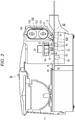
- FIG. 2 is a longitudinal sectional view illustrating a schematic configuration of the printer 10.
- FIG. 3 is a longitudinal sectional view illustrating the magnetic-ink reading device 50 incorporated in the printer 10.
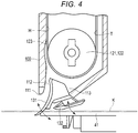
- FIG. 4 is a longitudinal sectional view illustrating main parts of a conveying path K and a reversing mechanism 100 incorporated in the printer 10.
- the printer 10 is incorporated in an ATM of a bank or the like or a POS (Point Of Sales) terminal of a store, a warehouse, or the like.
- P in FIG. 1 indicates a check (a sheet-like medium) and K in the figure indicates a conveying path for the check P. Characters by normal ink and MICR characters by magnetic ink are respectively printed on the check P.
- the printer 10 includes a housing 11.
- the conveying path K is formed in the housing 11.
- a medium inlet and outlet port 12 for inserting and discharging the check P from the outside is provided at the right end in FIG. 2 of the conveying path K.
- the check P is inserted from the medium inlet and outlet port 12 with a surface printed with the magnetic ink in advance directed downward in FIG. 1 .
- a control section 20 As illustrated in FIG. 2 , a control section 20, a conveying mechanism 40, a magnetic-ink reading device 50, a printing mechanism 90, and a reversing mechanism 100 are housed in the housing 11.
- the printing mechanism 90 is provided further on the medium inlet and outlet port 12 side than the magnetic-ink reading device 50.
- the reversing mechanism 100 is provided further on the medium inlet and outlet port 12 side than the printing mechanism 90.
- the control section 20 has a function of cooperatively controlling the conveying mechanism 40, the magnetic-ink reading device 50, the printing mechanism 90, the reversing mechanism 100, and the like.
- the conveying mechanism 40 includes a table 41 on which the sheet-like check P is conveyed in the left-right direction in FIG. 2 .
- a direction along the upper surface of the table 41 is a conveying direction K.
- the conveying mechanism 40 includes, along the table 41, a plurality of rollers including a feed roller 42 and a pinch roller 43.
- the conveying mechanism 40 includes, along the conveying path K, a paper sensor 44 configured to detect presence or absence of the check P.
- the magnetic-ink reading device 50 includes a magnetizing mechanism 60 configured to magnetize the magnetic ink of the check P on the conveying path K and a MICR head (magnetism detection head) 70 disposed near a conveying direction downstream side in the conveying path K of the magnetizing mechanism 60 and configured to read magnetism of the magnetized magnetic ink.
- a magnetizing mechanism 60 configured to magnetize the magnetic ink of the check P on the conveying path K
- a MICR head (magnetism detection head) 70 disposed near a conveying direction downstream side in the conveying path K of the magnetizing mechanism 60 and configured to read magnetism of the magnetized magnetic ink.
- the magnetizing mechanism 60 includes a magnet 61 magnetized on the surface of the check P conveyed along the conveying path K.
- the MICR head 70 detects residual magnetism of MICR characters.
- the MICR characters are read as a magnetic characteristic and a magnetic pattern and output to the control section 20 as an electric signal.
- the magnetic characteristic and the magnetic pattern of the MICR characters are registered in the control section 20 in advance.
- the MICR characters are identified by being collated with the registered magnetic characteristic and the magnetic pattern.
- the printing mechanism 90 includes an inkjet head 91 configured to perform printing instructed from the control section 20.
- the reversing mechanism 100 includes a rectangular parallelepiped housing 110.
- the housing 110 includes a reversing path H located on the left side in FIG. 3 and a retraction path T located on the right side in FIG. 3 .
- An opening section 111 is formed in a lower part of the housing 110 and disposed to be opposed to the conveying path K.
- the reversing mechanism 100 includes, on the MICR head 70 side of the opening section 111, a reversal introduction port 112 for introducing the check P into the reversing path H and includes, on the medium inlet and outlet port 12 side, a retraction introduction port 113 for introducing the check P into the retraction path T.
- a pair of rollers 121 and 122 are provided in the housing 110.
- An endless belt 123 is laid over the pair of rollers 121 and 122.
- the roller 121 is driven by a driving motor.
- the driving is controlled by the control section 20.
- Paths (the reversing path H and the retraction path T), through which the check P can pass, are formed between the surface of the endless belt 123 and the inner wall of the housing 110.
- a switching flapper 130 is disposed in the opening section 111 of the housing 110.
- the switching flapper 130 includes a first flapper 131 located on the left side in FIG. 4 and a second flapper 132 located on the right side in FIG. 4 .
- the first flapper 131 and the second flapper 132 are controlled by the control section 20 independently from each other.
- Both of the first flapper 131 and the second flapper 132 are set to be selectively movable between upper positions and lower positions. In the upper positions, both of the first flapper 131 and the second flapper 132 are held by a weak urging force that allows the flappers to move to the lower positions if the check P is placed on the flappers.
- the switching flapper 130 switches delivery to the reversal introduction port 112 side, the retraction introduction port 113 side, and the medium inlet and outlet port 12 side. That is, the check P is delivered to the reversal introduction port 112 if the first flapper 131 is in the lower position, delivered to the retraction introduction port 113 if the first flapper 131 is in the upper position and the second flapper 132 is in the lower position, and delivered to the medium inlet and outlet port 12 if both of the first flapper 131 and the second flapper 132 are in the lower positions.
- FIG. 5 is an explanatory diagram illustrating a relation between the reversing mechanism 100 and the switching flapper 130 during standby.
- FIG. 6 is an explanatory diagram illustrating a relation between the reversing mechanism 100 and the switching flapper 130 during check retraction.
- FIG. 7 is an explanatory diagram illustrating a relation between the reversing mechanism 100 and the switching flapper 130 during check discharge.
- FIG. 8 is an explanatory diagram illustrating a relation between the reversing mechanism 100 and the switching flapper 130 at a check reversal start time.
- both of the first flapper 131 and the second flapper 132 are in the upper positions.
- the check P is inserted by a user from the medium inlet and outlet port 12 of the housing 11 with the surface printed with the MICR characters directed downward.
- the inserted check P is conveyed by the conveying mechanism 40 toward the left direction in FIG. 5 along the conveying path K.
- the MICR characters pass through the magnetizing mechanism 60. At this time, the MICR characters are magnetized by the magnetism of the magnet 61.
- the conveyance by the conveying mechanism 40 is once stopped in the paper sensor 44 at a point in time when the check P reaches the left end in FIG. 2 of the conveying path K.
- the second flapper 132 moves to the lower position.
- the pair of rollers 121 and 122 of the reversing mechanism 100 is rotated in an arrow R1 direction in FIG. 6 . If the check P is conveyed in the right direction in FIG. 6 by the conveying mechanism 40 and the MICR characters reach the MICR head 70, a residual magnetic field generated by residual magnetism of the MICR characters is detected by the MICR head 70.
- the MICR characters are identified by the control section 20 from the magnetic characteristic and the magnetic pattern of the residual magnetism.
- the check P is introduced into the retraction path T of the reversing mechanism 100 from the retraction introduction port 113 by the second flapper 132 and the endless belt 123.
- the pair of rollers 121 and 122 of the reversing mechanism 100 is rotated in an arrow R2 direction in FIG. 7 to discharge the check P in the retraction path T onto the conveying path K from the reversing mechanism 100.
- the check P on the conveying path K is conveyed toward the left side in FIG. 2 by the conveying mechanism 40.
- the conveyance by the conveying mechanism 40 is once stopped in the paper sensor 44 at a point in time when the check P reaches the left end in FIG. 2 of the conveying path K.
- printing is performed by the inkjet head 91 of the printing mechanism 90 while the check P is conveyed toward the right direction in FIG. 2 .
- the second flapper 132 is moved to the lower position to prevent the check P from being conveyed to the medium inlet and outlet port 12 side.
- the pair of rollers 121 and 122 are rotated in the arrow R1 direction in FIG. 6 to introduce the check P into the retraction path T of the reversing mechanism 100.
- the reversing mechanism 100 reversely rotates the pair of rollers 121 and 122 to return the check P onto the conveying path K.
- the first flapper 131 and the second flapper 132 are moved to the upper positions to discharge the check P to the outside of the apparatus from the medium inlet and outlet port 12. In this way, the reading and the printing of the check P are completed.
- the check P is discharged from the medium inlet and outlet port 12 by the conveying mechanism 40.
- the check P is reversed to perform reading and printing on the rear surface of the check P.
- the first flapper 131 is moved to the lower position and the check P is introduced into the reversing path H of the reversing mechanism 100 from the reversal introduction port 112 while the check P is conveyed toward the right direction in FIG. 2 along the conveying path K by the conveying mechanism 40.
- the reversing mechanism 100 rotates the pair of rollers 121 and 122 in the arrow R2 direction in FIG. 8 and conveys the check P with the endless belt 123.
- the reversing mechanism 100 moves the check P from the reversing path H side to the retraction path T side in the housing 110 with the endless belt 123.
- the revering mechanism 100 further rotates the pair of rollers 121 and 122, conveys the check P with the endless belt 123, and discharges the check P from the retraction introduction port 113 of the housing 110.
- the discharged check P is guided on the upper surface of the second flapper 132.
- the second flapper 132 is moved to the lower position by a conveying force of the check P.
- the check P is returned to the conveying path K. In this way, the reversal of the check P is completed. Thereafter, reading, printing, and discharge are performed as explained above.
- the check P can be temporarily retracted using the reversing mechanism 100 set in general. Therefore, if magnetic ink printed on a medium is read and processed, it is unnecessary to add a new retraction path in order to prevent the medium from being pulled out by the user by mistake.
- the apparatus can be simplified and reduced in size. If processing such as reading and printing is performed on the check P, the check P is introduced into the retraction path T from the retraction introduction port 113 located on a far side from the MICR head 70 and the printing mechanism 90. Therefore, an unnatural bending force and a strong tensile force are not applied to the check P.
- a deficiency such as a reading error or a printing error does not occur during retraction of the check P.
- the reversal introduction port 112 on a side close from the MICR head 70 and the printing mechanism 90 can be used. Therefore, the distance from the MICR head 70 and the printing mechanism 90 to the reversing mechanism 100 can be reduced. The entire apparatus can be reduced in size.
- the retraction path T is used as a place to which the check P is temporarily retracted.
- the check P may be retracted to the reversing path H side.
- Timings of magnetization, reading, printing, retraction, and reversal are not limited to the timings explained above and can be changed as appropriate according to a processing method required for the check P.
- the magnetic-ink reading device may be used for a sheet-like medium other than the check P.
Landscapes
- Physics & Mathematics (AREA)
- General Physics & Mathematics (AREA)
- Engineering & Computer Science (AREA)
- Mechanical Engineering (AREA)
- Separation, Sorting, Adjustment, Or Bending Of Sheets To Be Conveyed (AREA)
- Printers Characterized By Their Purpose (AREA)
- Conveyance By Endless Belt Conveyors (AREA)
- Inspection Of Paper Currency And Valuable Securities (AREA)
Abstract
Description
- Embodiments described herein relate generally to a magnetic-ink reading device, a printer and a method related thereto.
- A printer apparatus used as an issuing apparatus for a receipt or a ticket prints a sheet-like medium (recording paper) and discharges the medium. In such a printer apparatus, a part of the medium sometimes protrudes from an inlet and outlet port of an apparatus housing during the printing. Therefore, a user sometimes grabs or pulls out the medium by mistake. This sometimes causes a breakdown of a conveying mechanism or a paper jam. In such an apparatus, a retraction path is separately provided in the apparatus to prevent the medium from being exposed to the user side. In general, for a reduction of the size of the apparatus, the retraction path is designed at a small curvature.
- Characters (MICR characters; Magnetic Ink character recognition) are sometimes printed on the surface of a medium such as a check or a bill of exchange with magnetic ink. Such MICR characters are read by a magnetic-ink reading device as explained below. If the user inserts the check or the like into the apparatus from the inlet and outlet port, the MICR characters are magnetized by a magnet. Subsequently, a residual magnetic field generated by residual magnetism of the MICR characters is detected by a MICR head (a magnetism detection head). The MICR characters are identified from a magnetic characteristic and a magnetic pattern of the residual magnetic field. It is possible to discriminate the check or the like with the MICR characters.
- Such a magnetic-ink reading device is incorporated and used in printers of an ATM and a POS. Such a magnetic-ink reading device magnetizes the MICR characters and detects the residual magnetic field to perform reading and printing. Even if such a device is provided, it is likely that the user grabs or pulls out the check or the like exposed from the inlet and outlet port during the reading or during the printing and the check or the like is made unusable.
- On the other hand, if the check or the like is temporarily retracted to the retraction path having the small curvature during the reading or during the printing, a deficiency is sometimes caused during the reading or during the printing. Therefore, there is a demand for an apparatus capable of performing appropriate reading and printing according to various situations.
- Related art is described in, for example,
JP-A-09-142708 - To solve the above cited problems, there is provided a magnetic-ink reading device comprising:
- a housing having a medium inlet and outlet port for inserting and pulling out a sheet-like medium printed using magnetic ink;
- a conveyor provided in the housing and configured to convey the medium along a conveying path;
- a magnetizing mechanism configured to magnetize the magnetic ink of the medium on the conveying path;
- a magnetism detection head disposed by the magnetizing mechanism along the conveying path and configured to read magnetism of the magnetized magnetic ink; and
- a reversing mechanism provided on the medium inlet and outlet port side of the conveying path and configured to reverse front and rear surfaces of the medium on a reversing path on an inside, wherein
- the reversing mechanism includes a retraction path configured to temporarily retract the medium when the magnetism of the medium is read by the magnetism detection head.
- Preferably the reversing mechanism may include, on the magnetism detection head side, a reversal introduction port arranged to introduce the medium into the reversing path, and on the medium inlet and outlet port side, a retraction introduction port arranged to introduce the medium into the retraction path, and
the magnetic-ink reading device may further include a switching flapper provided on the conveying path and configured to switch delivery to the reversal introduction port side, the retraction introduction port side, and the medium inlet and outlet port side. - Preferably the switching flapper may include a first flapper and a second flapper.
- Preferably the switching flapper may be configured to provide delivery to the reversal introduction port when the first flapper is in a lower position.
- Preferably the switching flapper may be configured to provide delivery to the retraction introduction port when the first flapper is in an upper position and the second flapper is in a lower position.
- Preferably the switching flapper may be configured to provide delivery to the medium inlet and outlet port when the first flapper is in an lower position and the second flapper is in a lower position.
- Preferably the switching flapper may be configured to perform an operation for delivering the medium to the retraction introduction port when magnetism of the medium is read by the magnetism detection head.
- Preferably the conveyor may include conveying rollers arranged to convey the medium.
- Preferably the reversing mechanism may include conveying rollers and an endless belt arranged to convey the medium.
- In another exemplary embodiment there is also provided a printer comprising:
- the magnetic-ink reading device according to any one of the preceding embodiments;
- a controller configured to generate printing information on the basis of information based on magnetism detected by the magnetism detection head; and
- a print head configured to print the printing information on the medium.
- In yet another exemplary embodiment there is also provided a method of operating a magnetic-ink reading device including a housing having a medium inlet and outlet port for inserting and pulling out a sheet-like medium printed using magnetic ink, the method comprising:
- conveying the medium along a conveying path;
- magnetizing, via a magnetizing mechanism, the magnetic ink of the medium on the conveying path;
- reading magnetism of the magnetized magnetic ink by a magnetism detection head disposed by the magnetizing mechanism along the conveying path; and
- reversing front and rear surfaces of the medium on a reversing path on an inside, and
- temporarily retracting the medium when the magnetism of the medium is read by the magnetism detection head in a retraction path.
- Preferably a reversal introduction port may be arranged on the magnetism detection head side to introduce the medium into the reversing path, and a retraction introduction port may be arranged on the medium inlet and outlet port side to introduce the medium into the retraction path, and
the method may further comprise switching delivery to the reversal introduction port side, the retraction introduction port side, and the medium inlet and outlet port side. - The above and other objects, features and advantages of the present invention will be made apparent from the following description of the preferred embodiments, given as non-limiting examples, with reference to the accompanying drawings, in which:
-
FIG. 1 is an exterior perspective view illustrating a printer incorporating a magnetic-ink reading device according to at least one embodiment; -
FIG. 2 is a longitudinal sectional view illustrating a schematic configuration of the printer; -
FIG. 3 is a longitudinal sectional view illustrating a main part of the printer; -
FIG. 4 is a longitudinal sectional view illustrating main parts of a conveying path and a reversing mechanism incorporated in the printer; -
FIG. 5 is an explanatory diagram illustrating a relation between the reversing mechanism and a switching flapper during standby; -
FIG. 6 is an explanatory diagram illustrating a relation between the reversing mechanism and the switching flapper during check retraction; -
FIG. 7 is an explanatory diagram illustrating a relation between the reversing mechanism and the switching flapper during check discharge; and -
FIG. 8 is an explanatory diagram illustrating a relation between the reversing mechanism and the switching flapper at a check reversal start time. - An object is to provide a magnetic-ink reading device and a printer that can prevent, when magnetic ink printed on a medium is read and processed, the medium from being pulled out by a user by mistake and can be simplified in structure and reduced in size.
- A magnetic-ink reading device according to at least one embodiment includes a housing and a conveying mechanism provided in the housing. A medium inlet and outlet port for inserting and pulling out a medium printed using magnetic ink is provided in the housing. The conveying mechanism (conveyor) conveys the medium along a conveying path. The magnetic-ink reading device includes a magnetizing mechanism configured to magnetize the magnetic ink of the medium on the conveying path and a magnetism detection head disposed near the magnetizing mechanism along the conveying path and configured to read magnetism of the magnetized magnetic ink. The magnetic-ink reading device further includes a reversing mechanism provided on the medium inlet and outlet port side of the conveying path and configured to reverse front and rear surfaces of the medium on a reversing path on an inside. The reversing mechanism includes a retraction path for temporarily retracting the medium when the magnetism of the medium is read by the magnetism detection head.
- At least one embodiment is explained below with reference to the drawings.
-
FIG. 1 is an exterior perspective view illustrating aprinter 10 incorporating a magnetic-ink reading device 50 according to at least one embodiment.FIG. 2 is a longitudinal sectional view illustrating a schematic configuration of theprinter 10.FIG. 3 is a longitudinal sectional view illustrating the magnetic-ink reading device 50 incorporated in theprinter 10.FIG. 4 is a longitudinal sectional view illustrating main parts of a conveying path K and a reversingmechanism 100 incorporated in theprinter 10. - The
printer 10 is incorporated in an ATM of a bank or the like or a POS (Point Of Sales) terminal of a store, a warehouse, or the like. P inFIG. 1 indicates a check (a sheet-like medium) and K in the figure indicates a conveying path for the check P. Characters by normal ink and MICR characters by magnetic ink are respectively printed on the check P. - The
printer 10 includes ahousing 11. The conveying path K is formed in thehousing 11. A medium inlet andoutlet port 12 for inserting and discharging the check P from the outside is provided at the right end inFIG. 2 of the conveying path K. In theprinter 10, the check P is inserted from the medium inlet andoutlet port 12 with a surface printed with the magnetic ink in advance directed downward inFIG. 1 . - As illustrated in
FIG. 2 , acontrol section 20, a conveyingmechanism 40, a magnetic-ink reading device 50, aprinting mechanism 90, and a reversingmechanism 100 are housed in thehousing 11. Theprinting mechanism 90 is provided further on the medium inlet andoutlet port 12 side than the magnetic-ink reading device 50. The reversingmechanism 100 is provided further on the medium inlet andoutlet port 12 side than theprinting mechanism 90. Thecontrol section 20 has a function of cooperatively controlling the conveyingmechanism 40, the magnetic-ink reading device 50, theprinting mechanism 90, the reversingmechanism 100, and the like. - The conveying
mechanism 40 includes a table 41 on which the sheet-like check P is conveyed in the left-right direction inFIG. 2 . A direction along the upper surface of the table 41 is a conveying direction K. The conveyingmechanism 40 includes, along the table 41, a plurality of rollers including afeed roller 42 and apinch roller 43. The conveyingmechanism 40 includes, along the conveying path K, apaper sensor 44 configured to detect presence or absence of the check P. - The magnetic-
ink reading device 50 includes a magnetizingmechanism 60 configured to magnetize the magnetic ink of the check P on the conveying path K and a MICR head (magnetism detection head) 70 disposed near a conveying direction downstream side in the conveying path K of the magnetizingmechanism 60 and configured to read magnetism of the magnetized magnetic ink. - The magnetizing
mechanism 60 includes amagnet 61 magnetized on the surface of the check P conveyed along the conveying path K. - The
MICR head 70 detects residual magnetism of MICR characters. The MICR characters are read as a magnetic characteristic and a magnetic pattern and output to thecontrol section 20 as an electric signal. The magnetic characteristic and the magnetic pattern of the MICR characters are registered in thecontrol section 20 in advance. The MICR characters are identified by being collated with the registered magnetic characteristic and the magnetic pattern. - The
printing mechanism 90 includes aninkjet head 91 configured to perform printing instructed from thecontrol section 20. - As illustrated in
FIG. 3 , the reversingmechanism 100 includes arectangular parallelepiped housing 110. Thehousing 110 includes a reversing path H located on the left side inFIG. 3 and a retraction path T located on the right side inFIG. 3 . Anopening section 111 is formed in a lower part of thehousing 110 and disposed to be opposed to the conveying path K. The reversingmechanism 100 includes, on theMICR head 70 side of theopening section 111, areversal introduction port 112 for introducing the check P into the reversing path H and includes, on the medium inlet andoutlet port 12 side, aretraction introduction port 113 for introducing the check P into the retraction path T. - A pair of
rollers housing 110. Anendless belt 123 is laid over the pair ofrollers roller 121 is driven by a driving motor. The driving is controlled by thecontrol section 20. Paths (the reversing path H and the retraction path T), through which the check P can pass, are formed between the surface of theendless belt 123 and the inner wall of thehousing 110. - As illustrated in
FIG. 4 , a switchingflapper 130 is disposed in theopening section 111 of thehousing 110. The switchingflapper 130 includes afirst flapper 131 located on the left side inFIG. 4 and asecond flapper 132 located on the right side inFIG. 4 . Thefirst flapper 131 and thesecond flapper 132 are controlled by thecontrol section 20 independently from each other. Both of thefirst flapper 131 and thesecond flapper 132 are set to be selectively movable between upper positions and lower positions. In the upper positions, both of thefirst flapper 131 and thesecond flapper 132 are held by a weak urging force that allows the flappers to move to the lower positions if the check P is placed on the flappers. - If the check P moves in the right direction in
FIG. 3 , the switchingflapper 130 switches delivery to thereversal introduction port 112 side, theretraction introduction port 113 side, and the medium inlet andoutlet port 12 side. That is, the check P is delivered to thereversal introduction port 112 if thefirst flapper 131 is in the lower position, delivered to theretraction introduction port 113 if thefirst flapper 131 is in the upper position and thesecond flapper 132 is in the lower position, and delivered to the medium inlet andoutlet port 12 if both of thefirst flapper 131 and thesecond flapper 132 are in the lower positions. - The
printer 10 configured as explained above performs magnetic ink reading and printing on the check P as explained below. Note thatFIG. 5 is an explanatory diagram illustrating a relation between the reversingmechanism 100 and the switchingflapper 130 during standby.FIG. 6 is an explanatory diagram illustrating a relation between the reversingmechanism 100 and the switchingflapper 130 during check retraction.FIG. 7 is an explanatory diagram illustrating a relation between the reversingmechanism 100 and the switchingflapper 130 during check discharge.FIG. 8 is an explanatory diagram illustrating a relation between the reversingmechanism 100 and the switchingflapper 130 at a check reversal start time. - If the check P is inserted or discharged, if reversal is not performed, or if retraction is not performed, as illustrated in
FIG. 5 , both of thefirst flapper 131 and thesecond flapper 132 are in the upper positions. - The check P is inserted by a user from the medium inlet and
outlet port 12 of thehousing 11 with the surface printed with the MICR characters directed downward. The inserted check P is conveyed by the conveyingmechanism 40 toward the left direction inFIG. 5 along the conveying path K. - If the check P reaches the magnetizing
mechanism 60, the MICR characters pass through the magnetizingmechanism 60. At this time, the MICR characters are magnetized by the magnetism of themagnet 61. The conveyance by the conveyingmechanism 40 is once stopped in thepaper sensor 44 at a point in time when the check P reaches the left end inFIG. 2 of the conveying path K. - Subsequently, as illustrated in
FIG. 6 , thesecond flapper 132 moves to the lower position. The pair ofrollers mechanism 100 is rotated in an arrow R1 direction inFIG. 6 . If the check P is conveyed in the right direction inFIG. 6 by the conveyingmechanism 40 and the MICR characters reach theMICR head 70, a residual magnetic field generated by residual magnetism of the MICR characters is detected by theMICR head 70. The MICR characters are identified by thecontrol section 20 from the magnetic characteristic and the magnetic pattern of the residual magnetism. At the same time, the check P is introduced into the retraction path T of the reversingmechanism 100 from theretraction introduction port 113 by thesecond flapper 132 and theendless belt 123. - Subsequently, if printing is performed on the check P, as illustrated in
FIG. 7 , the pair ofrollers mechanism 100 is rotated in an arrow R2 direction inFIG. 7 to discharge the check P in the retraction path T onto the conveying path K from the reversingmechanism 100. - The check P on the conveying path K is conveyed toward the left side in
FIG. 2 by the conveyingmechanism 40. The conveyance by the conveyingmechanism 40 is once stopped in thepaper sensor 44 at a point in time when the check P reaches the left end inFIG. 2 of the conveying path K. Subsequently, printing is performed by theinkjet head 91 of theprinting mechanism 90 while the check P is conveyed toward the right direction inFIG. 2 . At this time, as illustrated inFIG. 6 , thesecond flapper 132 is moved to the lower position to prevent the check P from being conveyed to the medium inlet andoutlet port 12 side. The pair ofrollers FIG. 6 to introduce the check P into the retraction path T of the reversingmechanism 100. - After the printing is completed, as illustrated in
FIG. 7 , the reversingmechanism 100 reversely rotates the pair ofrollers FIG. 2 by the conveyingmechanism 40, thefirst flapper 131 and thesecond flapper 132 are moved to the upper positions to discharge the check P to the outside of the apparatus from the medium inlet andoutlet port 12. In this way, the reading and the printing of the check P are completed. The check P is discharged from the medium inlet andoutlet port 12 by the conveyingmechanism 40. - Subsequently, the check P is reversed to perform reading and printing on the rear surface of the check P. After the reading and the printing of the check P are completed as explained above, as illustrated in
FIG. 8 , thefirst flapper 131 is moved to the lower position and the check P is introduced into the reversing path H of the reversingmechanism 100 from thereversal introduction port 112 while the check P is conveyed toward the right direction inFIG. 2 along the conveying path K by the conveyingmechanism 40. The reversingmechanism 100 rotates the pair ofrollers FIG. 8 and conveys the check P with theendless belt 123. The reversingmechanism 100 moves the check P from the reversing path H side to the retraction path T side in thehousing 110 with theendless belt 123. Therevering mechanism 100 further rotates the pair ofrollers endless belt 123, and discharges the check P from theretraction introduction port 113 of thehousing 110. As illustrated inFIG. 7 , the discharged check P is guided on the upper surface of thesecond flapper 132. At this time, thesecond flapper 132 is moved to the lower position by a conveying force of the check P. The check P is returned to the conveying path K. In this way, the reversal of the check P is completed. Thereafter, reading, printing, and discharge are performed as explained above. - In this way, with the
printer 10 according to this embodiment, the check P can be temporarily retracted using the reversingmechanism 100 set in general. Therefore, if magnetic ink printed on a medium is read and processed, it is unnecessary to add a new retraction path in order to prevent the medium from being pulled out by the user by mistake. The apparatus can be simplified and reduced in size. If processing such as reading and printing is performed on the check P, the check P is introduced into the retraction path T from theretraction introduction port 113 located on a far side from theMICR head 70 and theprinting mechanism 90. Therefore, an unnatural bending force and a strong tensile force are not applied to the check P. A deficiency such as a reading error or a printing error does not occur during retraction of the check P. On the other hand, if the check P is reversed, since the processing such as reading and printing is not performed, thereversal introduction port 112 on a side close from theMICR head 70 and theprinting mechanism 90 can be used. Therefore, the distance from theMICR head 70 and theprinting mechanism 90 to the reversingmechanism 100 can be reduced. The entire apparatus can be reduced in size. - In at least one embodiment explained above, the retraction path T is used as a place to which the check P is temporarily retracted. However, if the check P is thin and has sufficient flexibility, the check P may be retracted to the reversing path H side. Timings of magnetization, reading, printing, retraction, and reversal are not limited to the timings explained above and can be changed as appropriate according to a processing method required for the check P. Further, the magnetic-ink reading device may be used for a sheet-like medium other than the check P.
- At least one embodiment is explained above. However, the at least one embodiment is presented as an example and is not intended to limit the scope of the invention. Other embodiments can be implemented in other various forms. Various omissions, substitutions, and changes can be performed without departing from the scope of the invention. The embodiments and modifications of the embodiments are included in the scope and the gist of the invention and included in the inventions described in claims and the scope of equivalents of the inventions.
Claims (12)
- A magnetic-ink reading device comprising:a housing having a medium inlet and outlet port for inserting and pulling out a sheet-like medium printed using magnetic ink;a conveyor provided in the housing and configured to convey the medium along a conveying path;a magnetizing mechanism configured to magnetize the magnetic ink of the medium on the conveying path;a magnetism detection head disposed by the magnetizing mechanism along the conveying path and configured to read magnetism of the magnetized magnetic ink; anda reversing mechanism provided on the medium inlet and outlet port side of the conveying path and configured to reverse front and rear surfaces of the medium on a reversing path on an inside, whereinthe reversing mechanism includes a retraction path configured to temporarily retract the medium when the magnetism of the medium is read by the magnetism detection head.
- The magnetic-ink reading device according to claim 1, wherein
the reversing mechanism includes, on the magnetism detection head side, a reversal introduction port arranged to introduce the medium into the reversing path, and on the medium inlet and outlet port side, a retraction introduction port arranged to introduce the medium into the retraction path, and
the magnetic-ink reading device further includes a switching flapper provided on the conveying path and configured to switch delivery to the reversal introduction port side, the retraction introduction port side, and the medium inlet and outlet port side. - The magnetic-ink reading device according to claim 2, wherein the switching flapper includes a first flapper and a second flapper.
- The magnetic-ink reading device according to claim 3, wherein the switching flapper is configured to provide delivery to the reversal introduction port when the first flapper is in a lower position.
- The magnetic-ink reading device according to claim 3 or 4, wherein the switching flapper is configured to provide delivery to the retraction introduction port when the first flapper is in an upper position and the second flapper is in a lower position.
- The magnetic-ink reading device according to any one of claims 3 to 5, wherein the switching flapper is configured to provide delivery to the medium inlet and outlet port when the first flapper is in an lower position and the second flapper is in a lower position.
- The magnetic-ink reading device according to claim 2 or 3, wherein the switching flapper is configured to perform an operation for delivering the medium to the retraction introduction port when magnetism of the medium is read by the magnetism detection head.
- The magnetic-ink reading device according to any one of claims 1 to 7, wherein the conveyor includes conveying rollers arranged to convey the medium.
- The magnetic-ink reading device according to any one of claims 1 to 8, wherein the reversing mechanism includes conveying rollers and an endless belt arranged to convey the medium.
- A printer comprising:the magnetic-ink reading device according to any one of claims 1 to 9;a controller configured to generate printing information on the basis of information based on magnetism detected by the magnetism detection head; anda print head configured to print the printing information on the medium.
- A method of operating a magnetic-ink reading device including a housing having a medium inlet and outlet port for inserting and pulling out a sheet-like medium printed using magnetic ink, the method comprising:conveying the medium along a conveying path;magnetizing, via a magnetizing mechanism, the magnetic ink of the medium on the conveying path;reading magnetism of the magnetized magnetic ink by a magnetism detection head disposed by the magnetizing mechanism along the conveying path; andreversing front and rear surfaces of the medium on a reversing path on an inside, andtemporarily retracting the medium when the magnetism of the medium is read by the magnetism detection head in a retraction path.
- The method according to claim 11, wherein
a reversal introduction port is arranged on the magnetism detection head side to introduce the medium into the reversing path, and a retraction introduction port is arranged on the medium inlet and outlet port side to introduce the medium into the retraction path, and
the method further comprises switching delivery to the reversal introduction port side, the retraction introduction port side, and the medium inlet and outlet port side.
Applications Claiming Priority (1)
| Application Number | Priority Date | Filing Date | Title |
|---|---|---|---|
| JP2017236390A JP6980506B2 (en) | 2017-12-08 | 2017-12-08 | Magnetic ink reader and printer |
Publications (2)
| Publication Number | Publication Date |
|---|---|
| EP3495299A1 true EP3495299A1 (en) | 2019-06-12 |
| EP3495299B1 EP3495299B1 (en) | 2021-08-11 |
Family
ID=64606825
Family Applications (1)
| Application Number | Title | Priority Date | Filing Date |
|---|---|---|---|
| EP18210358.0A Active EP3495299B1 (en) | 2017-12-08 | 2018-12-05 | Magnetic-ink reading device and printer |
Country Status (4)
| Country | Link |
|---|---|
| US (2) | US10843492B2 (en) |
| EP (1) | EP3495299B1 (en) |
| JP (1) | JP6980506B2 (en) |
| CN (1) | CN110014733B (en) |
Families Citing this family (4)
| Publication number | Priority date | Publication date | Assignee | Title |
|---|---|---|---|---|
| JP6980506B2 (en) * | 2017-12-08 | 2021-12-15 | 東芝テック株式会社 | Magnetic ink reader and printer |
| JP7551346B2 (en) * | 2020-06-16 | 2024-09-17 | 東芝テック株式会社 | Magnetic ink reader and printer |
| JP2021195251A (en) * | 2020-06-17 | 2021-12-27 | 東芝テック株式会社 | Paper sheet conveying device and printer |
| JP7190116B2 (en) * | 2021-02-19 | 2022-12-15 | 大日本印刷株式会社 | duplex printer |
Citations (4)
| Publication number | Priority date | Publication date | Assignee | Title |
|---|---|---|---|---|
| JPH09142708A (en) | 1995-11-24 | 1997-06-03 | Star Micronics Co Ltd | Paper ejection device |
| US6257783B1 (en) * | 1999-03-30 | 2001-07-10 | Seiko Epson Corporation | Printer and control method for the same |
| US20100295232A1 (en) * | 2009-05-22 | 2010-11-25 | Spall J Michael | Document processing device with optimised reversing track layout and single image capacity |
| EP2481598A1 (en) * | 2009-09-24 | 2012-08-01 | Shandong New Beiyang Information Technology Co., Ltd. | Processing apparatus and method for recording medium embedded with information |
Family Cites Families (13)
| Publication number | Priority date | Publication date | Assignee | Title |
|---|---|---|---|---|
| JPH03212787A (en) * | 1990-01-18 | 1991-09-18 | Toshiba Corp | Recording medium processor |
| WO1994010649A1 (en) * | 1992-10-30 | 1994-05-11 | Microbilt Corporation | Multi-reader transaction terminal |
| US5422467A (en) * | 1993-01-15 | 1995-06-06 | Interbold | Article depositing apparatus |
| JP3879799B2 (en) * | 1997-08-06 | 2007-02-14 | セイコーエプソン株式会社 | Compound processing equipment |
| JP2000272112A (en) * | 1999-03-24 | 2000-10-03 | Ricoh Co Ltd | Recording method and apparatus |
| JP2000344428A (en) * | 1999-03-30 | 2000-12-12 | Seiko Epson Corp | Printing apparatus and control method thereof |
| KR100412494B1 (en) * | 2001-09-29 | 2003-12-31 | 삼성전자주식회사 | Paper deeding apparatus for Image forming apparatus and paper feeding method used the same |
| JP4096642B2 (en) | 2002-06-21 | 2008-06-04 | セイコーエプソン株式会社 | Image data processing method and image data processing system |
| JP4086706B2 (en) * | 2003-04-18 | 2008-05-14 | キヤノン株式会社 | Recording device |
| US8351092B2 (en) * | 2007-05-31 | 2013-01-08 | Nidec Sankyo Corporation | Image reader and medium processor |
| JP5673126B2 (en) * | 2011-01-21 | 2015-02-18 | ブラザー工業株式会社 | Image recording device |
| JP5669696B2 (en) * | 2011-08-19 | 2015-02-12 | キヤノン株式会社 | RECORDING DEVICE AND RECORDING MEDIUM CONVEYING METHOD |
| JP6980506B2 (en) * | 2017-12-08 | 2021-12-15 | 東芝テック株式会社 | Magnetic ink reader and printer |
-
2017
- 2017-12-08 JP JP2017236390A patent/JP6980506B2/en active Active
-
2018
- 2018-11-30 US US16/205,878 patent/US10843492B2/en active Active
- 2018-12-05 EP EP18210358.0A patent/EP3495299B1/en active Active
- 2018-12-06 CN CN201811489053.9A patent/CN110014733B/en active Active
-
2020
- 2020-09-30 US US17/039,729 patent/US11752786B2/en active Active
Patent Citations (4)
| Publication number | Priority date | Publication date | Assignee | Title |
|---|---|---|---|---|
| JPH09142708A (en) | 1995-11-24 | 1997-06-03 | Star Micronics Co Ltd | Paper ejection device |
| US6257783B1 (en) * | 1999-03-30 | 2001-07-10 | Seiko Epson Corporation | Printer and control method for the same |
| US20100295232A1 (en) * | 2009-05-22 | 2010-11-25 | Spall J Michael | Document processing device with optimised reversing track layout and single image capacity |
| EP2481598A1 (en) * | 2009-09-24 | 2012-08-01 | Shandong New Beiyang Information Technology Co., Ltd. | Processing apparatus and method for recording medium embedded with information |
Also Published As
| Publication number | Publication date |
|---|---|
| CN110014733A (en) | 2019-07-16 |
| US20190176496A1 (en) | 2019-06-13 |
| US11752786B2 (en) | 2023-09-12 |
| JP2019104555A (en) | 2019-06-27 |
| CN110014733B (en) | 2020-11-24 |
| EP3495299B1 (en) | 2021-08-11 |
| US20210016581A1 (en) | 2021-01-21 |
| JP6980506B2 (en) | 2021-12-15 |
| US10843492B2 (en) | 2020-11-24 |
Similar Documents
| Publication | Publication Date | Title |
|---|---|---|
| US11752786B2 (en) | Magnetic-ink reading device and printer | |
| CN101174297A (en) | Method and device for processing recording medium printed with magnetic ink characters | |
| EP2481598A1 (en) | Processing apparatus and method for recording medium embedded with information | |
| WO2002100648A1 (en) | Printer with sheet reversal mechanism | |
| US8964195B2 (en) | Recording device for detecting the length of a recording medium, a control device, a control method for a recording device and a recording medium | |
| US12434940B2 (en) | Printing apparatus | |
| US9987857B2 (en) | Printing device, and printing method | |
| JP6946121B2 (en) | Magnetic ink reader and printer | |
| US11529817B2 (en) | Paper conveyance device and printer | |
| CN204172499U (en) | Printing device | |
| US12139358B2 (en) | Magnetic ink reading device and printer | |
| TW458892B (en) | Printer device, the control method and information record media | |
| CN113459683A (en) | Printer and control method of printer | |
| JP4599845B2 (en) | Printing device | |
| JP5927281B2 (en) | Image erasing device | |
| JP2004243767A (en) | Printing apparatus and printing method | |
| JP4032077B2 (en) | Recording device | |
| JP4931468B2 (en) | Media processing device | |
| JP2024176937A (en) | Media Processing Device | |
| JP5703953B2 (en) | Media processing device | |
| JP4669339B2 (en) | Printing device | |
| JP2015054467A (en) | Image erasing device | |
| JP4270706B2 (en) | Passbook / slip printer | |
| JP2020170340A (en) | Media processing device control method and media processing device | |
| JP2004243766A (en) | Printing apparatus and printing method |
Legal Events
| Date | Code | Title | Description |
|---|---|---|---|
| PUAI | Public reference made under article 153(3) epc to a published international application that has entered the european phase |
Free format text: ORIGINAL CODE: 0009012 |
|
| STAA | Information on the status of an ep patent application or granted ep patent |
Free format text: STATUS: THE APPLICATION HAS BEEN PUBLISHED |
|
| AK | Designated contracting states |
Kind code of ref document: A1 Designated state(s): AL AT BE BG CH CY CZ DE DK EE ES FI FR GB GR HR HU IE IS IT LI LT LU LV MC MK MT NL NO PL PT RO RS SE SI SK SM TR |
|
| AX | Request for extension of the european patent |
Extension state: BA ME |
|
| STAA | Information on the status of an ep patent application or granted ep patent |
Free format text: STATUS: REQUEST FOR EXAMINATION WAS MADE |
|
| 17P | Request for examination filed |
Effective date: 20191212 |
|
| RBV | Designated contracting states (corrected) |
Designated state(s): AL AT BE BG CH CY CZ DE DK EE ES FI FR GB GR HR HU IE IS IT LI LT LU LV MC MK MT NL NO PL PT RO RS SE SI SK SM TR |
|
| GRAP | Despatch of communication of intention to grant a patent |
Free format text: ORIGINAL CODE: EPIDOSNIGR1 |
|
| STAA | Information on the status of an ep patent application or granted ep patent |
Free format text: STATUS: GRANT OF PATENT IS INTENDED |
|
| RIC1 | Information provided on ipc code assigned before grant |
Ipc: B65H 5/26 20060101ALI20210215BHEP Ipc: B65H 85/00 20060101AFI20210215BHEP Ipc: B65H 29/58 20060101ALI20210215BHEP |
|
| INTG | Intention to grant announced |
Effective date: 20210301 |
|
| GRAS | Grant fee paid |
Free format text: ORIGINAL CODE: EPIDOSNIGR3 |
|
| GRAA | (expected) grant |
Free format text: ORIGINAL CODE: 0009210 |
|
| STAA | Information on the status of an ep patent application or granted ep patent |
Free format text: STATUS: THE PATENT HAS BEEN GRANTED |
|
| AK | Designated contracting states |
Kind code of ref document: B1 Designated state(s): AL AT BE BG CH CY CZ DE DK EE ES FI FR GB GR HR HU IE IS IT LI LT LU LV MC MK MT NL NO PL PT RO RS SE SI SK SM TR |
|
| REG | Reference to a national code |
Ref country code: CH Ref legal event code: EP |
|
| REG | Reference to a national code |
Ref country code: DE Ref legal event code: R096 Ref document number: 602018021561 Country of ref document: DE |
|
| REG | Reference to a national code |
Ref country code: IE Ref legal event code: FG4D Ref country code: AT Ref legal event code: REF Ref document number: 1419205 Country of ref document: AT Kind code of ref document: T Effective date: 20210915 |
|
| REG | Reference to a national code |
Ref country code: LT Ref legal event code: MG9D |
|
| REG | Reference to a national code |
Ref country code: NL Ref legal event code: MP Effective date: 20210811 |
|
| REG | Reference to a national code |
Ref country code: AT Ref legal event code: MK05 Ref document number: 1419205 Country of ref document: AT Kind code of ref document: T Effective date: 20210811 |
|
| PG25 | Lapsed in a contracting state [announced via postgrant information from national office to epo] |
Ref country code: NO Free format text: LAPSE BECAUSE OF FAILURE TO SUBMIT A TRANSLATION OF THE DESCRIPTION OR TO PAY THE FEE WITHIN THE PRESCRIBED TIME-LIMIT Effective date: 20211111 Ref country code: PT Free format text: LAPSE BECAUSE OF FAILURE TO SUBMIT A TRANSLATION OF THE DESCRIPTION OR TO PAY THE FEE WITHIN THE PRESCRIBED TIME-LIMIT Effective date: 20211213 Ref country code: LT Free format text: LAPSE BECAUSE OF FAILURE TO SUBMIT A TRANSLATION OF THE DESCRIPTION OR TO PAY THE FEE WITHIN THE PRESCRIBED TIME-LIMIT Effective date: 20210811 Ref country code: BG Free format text: LAPSE BECAUSE OF FAILURE TO SUBMIT A TRANSLATION OF THE DESCRIPTION OR TO PAY THE FEE WITHIN THE PRESCRIBED TIME-LIMIT Effective date: 20211111 Ref country code: AT Free format text: LAPSE BECAUSE OF FAILURE TO SUBMIT A TRANSLATION OF THE DESCRIPTION OR TO PAY THE FEE WITHIN THE PRESCRIBED TIME-LIMIT Effective date: 20210811 Ref country code: HR Free format text: LAPSE BECAUSE OF FAILURE TO SUBMIT A TRANSLATION OF THE DESCRIPTION OR TO PAY THE FEE WITHIN THE PRESCRIBED TIME-LIMIT Effective date: 20210811 Ref country code: FI Free format text: LAPSE BECAUSE OF FAILURE TO SUBMIT A TRANSLATION OF THE DESCRIPTION OR TO PAY THE FEE WITHIN THE PRESCRIBED TIME-LIMIT Effective date: 20210811 Ref country code: ES Free format text: LAPSE BECAUSE OF FAILURE TO SUBMIT A TRANSLATION OF THE DESCRIPTION OR TO PAY THE FEE WITHIN THE PRESCRIBED TIME-LIMIT Effective date: 20210811 Ref country code: SE Free format text: LAPSE BECAUSE OF FAILURE TO SUBMIT A TRANSLATION OF THE DESCRIPTION OR TO PAY THE FEE WITHIN THE PRESCRIBED TIME-LIMIT Effective date: 20210811 Ref country code: RS Free format text: LAPSE BECAUSE OF FAILURE TO SUBMIT A TRANSLATION OF THE DESCRIPTION OR TO PAY THE FEE WITHIN THE PRESCRIBED TIME-LIMIT Effective date: 20210811 |
|
| PG25 | Lapsed in a contracting state [announced via postgrant information from national office to epo] |
Ref country code: PL Free format text: LAPSE BECAUSE OF FAILURE TO SUBMIT A TRANSLATION OF THE DESCRIPTION OR TO PAY THE FEE WITHIN THE PRESCRIBED TIME-LIMIT Effective date: 20210811 Ref country code: LV Free format text: LAPSE BECAUSE OF FAILURE TO SUBMIT A TRANSLATION OF THE DESCRIPTION OR TO PAY THE FEE WITHIN THE PRESCRIBED TIME-LIMIT Effective date: 20210811 Ref country code: GR Free format text: LAPSE BECAUSE OF FAILURE TO SUBMIT A TRANSLATION OF THE DESCRIPTION OR TO PAY THE FEE WITHIN THE PRESCRIBED TIME-LIMIT Effective date: 20211112 |
|
| PG25 | Lapsed in a contracting state [announced via postgrant information from national office to epo] |
Ref country code: NL Free format text: LAPSE BECAUSE OF FAILURE TO SUBMIT A TRANSLATION OF THE DESCRIPTION OR TO PAY THE FEE WITHIN THE PRESCRIBED TIME-LIMIT Effective date: 20210811 |
|
| PG25 | Lapsed in a contracting state [announced via postgrant information from national office to epo] |
Ref country code: DK Free format text: LAPSE BECAUSE OF FAILURE TO SUBMIT A TRANSLATION OF THE DESCRIPTION OR TO PAY THE FEE WITHIN THE PRESCRIBED TIME-LIMIT Effective date: 20210811 |
|
| REG | Reference to a national code |
Ref country code: DE Ref legal event code: R097 Ref document number: 602018021561 Country of ref document: DE |
|
| PG25 | Lapsed in a contracting state [announced via postgrant information from national office to epo] |
Ref country code: SM Free format text: LAPSE BECAUSE OF FAILURE TO SUBMIT A TRANSLATION OF THE DESCRIPTION OR TO PAY THE FEE WITHIN THE PRESCRIBED TIME-LIMIT Effective date: 20210811 Ref country code: SK Free format text: LAPSE BECAUSE OF FAILURE TO SUBMIT A TRANSLATION OF THE DESCRIPTION OR TO PAY THE FEE WITHIN THE PRESCRIBED TIME-LIMIT Effective date: 20210811 Ref country code: RO Free format text: LAPSE BECAUSE OF FAILURE TO SUBMIT A TRANSLATION OF THE DESCRIPTION OR TO PAY THE FEE WITHIN THE PRESCRIBED TIME-LIMIT Effective date: 20210811 Ref country code: EE Free format text: LAPSE BECAUSE OF FAILURE TO SUBMIT A TRANSLATION OF THE DESCRIPTION OR TO PAY THE FEE WITHIN THE PRESCRIBED TIME-LIMIT Effective date: 20210811 Ref country code: CZ Free format text: LAPSE BECAUSE OF FAILURE TO SUBMIT A TRANSLATION OF THE DESCRIPTION OR TO PAY THE FEE WITHIN THE PRESCRIBED TIME-LIMIT Effective date: 20210811 Ref country code: AL Free format text: LAPSE BECAUSE OF FAILURE TO SUBMIT A TRANSLATION OF THE DESCRIPTION OR TO PAY THE FEE WITHIN THE PRESCRIBED TIME-LIMIT Effective date: 20210811 |
|
| PLBE | No opposition filed within time limit |
Free format text: ORIGINAL CODE: 0009261 |
|
| STAA | Information on the status of an ep patent application or granted ep patent |
Free format text: STATUS: NO OPPOSITION FILED WITHIN TIME LIMIT |
|
| 26N | No opposition filed |
Effective date: 20220512 |
|
| PG25 | Lapsed in a contracting state [announced via postgrant information from national office to epo] |
Ref country code: MC Free format text: LAPSE BECAUSE OF FAILURE TO SUBMIT A TRANSLATION OF THE DESCRIPTION OR TO PAY THE FEE WITHIN THE PRESCRIBED TIME-LIMIT Effective date: 20210811 Ref country code: IT Free format text: LAPSE BECAUSE OF FAILURE TO SUBMIT A TRANSLATION OF THE DESCRIPTION OR TO PAY THE FEE WITHIN THE PRESCRIBED TIME-LIMIT Effective date: 20210811 |
|
| REG | Reference to a national code |
Ref country code: CH Ref legal event code: PL |
|
| PG25 | Lapsed in a contracting state [announced via postgrant information from national office to epo] |
Ref country code: SI Free format text: LAPSE BECAUSE OF FAILURE TO SUBMIT A TRANSLATION OF THE DESCRIPTION OR TO PAY THE FEE WITHIN THE PRESCRIBED TIME-LIMIT Effective date: 20210811 |
|
| REG | Reference to a national code |
Ref country code: BE Ref legal event code: MM Effective date: 20211231 |
|
| PG25 | Lapsed in a contracting state [announced via postgrant information from national office to epo] |
Ref country code: LU Free format text: LAPSE BECAUSE OF NON-PAYMENT OF DUE FEES Effective date: 20211205 Ref country code: IE Free format text: LAPSE BECAUSE OF NON-PAYMENT OF DUE FEES Effective date: 20211205 |
|
| PG25 | Lapsed in a contracting state [announced via postgrant information from national office to epo] |
Ref country code: BE Free format text: LAPSE BECAUSE OF NON-PAYMENT OF DUE FEES Effective date: 20211231 |
|
| PG25 | Lapsed in a contracting state [announced via postgrant information from national office to epo] |
Ref country code: LI Free format text: LAPSE BECAUSE OF NON-PAYMENT OF DUE FEES Effective date: 20211231 Ref country code: CH Free format text: LAPSE BECAUSE OF NON-PAYMENT OF DUE FEES Effective date: 20211231 |
|
| PG25 | Lapsed in a contracting state [announced via postgrant information from national office to epo] |
Ref country code: CY Free format text: LAPSE BECAUSE OF FAILURE TO SUBMIT A TRANSLATION OF THE DESCRIPTION OR TO PAY THE FEE WITHIN THE PRESCRIBED TIME-LIMIT Effective date: 20210811 |
|
| PG25 | Lapsed in a contracting state [announced via postgrant information from national office to epo] |
Ref country code: HU Free format text: LAPSE BECAUSE OF FAILURE TO SUBMIT A TRANSLATION OF THE DESCRIPTION OR TO PAY THE FEE WITHIN THE PRESCRIBED TIME-LIMIT; INVALID AB INITIO Effective date: 20181205 |
|
| PG25 | Lapsed in a contracting state [announced via postgrant information from national office to epo] |
Ref country code: MK Free format text: LAPSE BECAUSE OF FAILURE TO SUBMIT A TRANSLATION OF THE DESCRIPTION OR TO PAY THE FEE WITHIN THE PRESCRIBED TIME-LIMIT Effective date: 20210811 |
|
| PG25 | Lapsed in a contracting state [announced via postgrant information from national office to epo] |
Ref country code: MT Free format text: LAPSE BECAUSE OF FAILURE TO SUBMIT A TRANSLATION OF THE DESCRIPTION OR TO PAY THE FEE WITHIN THE PRESCRIBED TIME-LIMIT Effective date: 20210811 |
|
| PGFP | Annual fee paid to national office [announced via postgrant information from national office to epo] |
Ref country code: FR Payment date: 20250930 Year of fee payment: 8 |
|
| PG25 | Lapsed in a contracting state [announced via postgrant information from national office to epo] |
Ref country code: TR Free format text: LAPSE BECAUSE OF FAILURE TO SUBMIT A TRANSLATION OF THE DESCRIPTION OR TO PAY THE FEE WITHIN THE PRESCRIBED TIME-LIMIT Effective date: 20210811 |
|
| PGFP | Annual fee paid to national office [announced via postgrant information from national office to epo] |
Ref country code: DE Payment date: 20250930 Year of fee payment: 8 |
|
| PGFP | Annual fee paid to national office [announced via postgrant information from national office to epo] |
Ref country code: GB Payment date: 20251001 Year of fee payment: 8 |