EP3495204A1 - Open roof construction for a vehicle - Google Patents
Open roof construction for a vehicle Download PDFInfo
- Publication number
- EP3495204A1 EP3495204A1 EP18200604.9A EP18200604A EP3495204A1 EP 3495204 A1 EP3495204 A1 EP 3495204A1 EP 18200604 A EP18200604 A EP 18200604A EP 3495204 A1 EP3495204 A1 EP 3495204A1
- Authority
- EP
- European Patent Office
- Prior art keywords
- light
- fibres
- cover
- emitting layer
- connector
- Prior art date
- Legal status (The legal status is an assumption and is not a legal conclusion. Google has not performed a legal analysis and makes no representation as to the accuracy of the status listed.)
- Granted
Links
Images



Classifications
-
- B—PERFORMING OPERATIONS; TRANSPORTING
- B60—VEHICLES IN GENERAL
- B60Q—ARRANGEMENT OF SIGNALLING OR LIGHTING DEVICES, THE MOUNTING OR SUPPORTING THEREOF OR CIRCUITS THEREFOR, FOR VEHICLES IN GENERAL
- B60Q3/00—Arrangement of lighting devices for vehicle interiors; Lighting devices specially adapted for vehicle interiors
- B60Q3/20—Arrangement of lighting devices for vehicle interiors; Lighting devices specially adapted for vehicle interiors for lighting specific fittings of passenger or driving compartments; mounted on specific fittings of passenger or driving compartments
- B60Q3/208—Sun roofs; Windows
-
- B—PERFORMING OPERATIONS; TRANSPORTING
- B60—VEHICLES IN GENERAL
- B60J—WINDOWS, WINDSCREENS, NON-FIXED ROOFS, DOORS, OR SIMILAR DEVICES FOR VEHICLES; REMOVABLE EXTERNAL PROTECTIVE COVERINGS SPECIALLY ADAPTED FOR VEHICLES
- B60J7/00—Non-fixed roofs; Roofs with movable panels, e.g. rotary sunroofs
- B60J7/02—Non-fixed roofs; Roofs with movable panels, e.g. rotary sunroofs of sliding type, e.g. comprising guide shoes
- B60J7/04—Non-fixed roofs; Roofs with movable panels, e.g. rotary sunroofs of sliding type, e.g. comprising guide shoes with rigid plate-like element or elements, e.g. open roofs with harmonica-type folding rigid panels
-
- B—PERFORMING OPERATIONS; TRANSPORTING
- B60—VEHICLES IN GENERAL
- B60Q—ARRANGEMENT OF SIGNALLING OR LIGHTING DEVICES, THE MOUNTING OR SUPPORTING THEREOF OR CIRCUITS THEREFOR, FOR VEHICLES IN GENERAL
- B60Q3/00—Arrangement of lighting devices for vehicle interiors; Lighting devices specially adapted for vehicle interiors
- B60Q3/60—Arrangement of lighting devices for vehicle interiors; Lighting devices specially adapted for vehicle interiors characterised by optical aspects
- B60Q3/62—Arrangement of lighting devices for vehicle interiors; Lighting devices specially adapted for vehicle interiors characterised by optical aspects using light guides
-
- B—PERFORMING OPERATIONS; TRANSPORTING
- B60—VEHICLES IN GENERAL
- B60Q—ARRANGEMENT OF SIGNALLING OR LIGHTING DEVICES, THE MOUNTING OR SUPPORTING THEREOF OR CIRCUITS THEREFOR, FOR VEHICLES IN GENERAL
- B60Q3/00—Arrangement of lighting devices for vehicle interiors; Lighting devices specially adapted for vehicle interiors
- B60Q3/60—Arrangement of lighting devices for vehicle interiors; Lighting devices specially adapted for vehicle interiors characterised by optical aspects
- B60Q3/62—Arrangement of lighting devices for vehicle interiors; Lighting devices specially adapted for vehicle interiors characterised by optical aspects using light guides
- B60Q3/64—Arrangement of lighting devices for vehicle interiors; Lighting devices specially adapted for vehicle interiors characterised by optical aspects using light guides for a single lighting device
-
- B—PERFORMING OPERATIONS; TRANSPORTING
- B60—VEHICLES IN GENERAL
- B60J—WINDOWS, WINDSCREENS, NON-FIXED ROOFS, DOORS, OR SIMILAR DEVICES FOR VEHICLES; REMOVABLE EXTERNAL PROTECTIVE COVERINGS SPECIALLY ADAPTED FOR VEHICLES
- B60J7/00—Non-fixed roofs; Roofs with movable panels, e.g. rotary sunroofs
- B60J7/02—Non-fixed roofs; Roofs with movable panels, e.g. rotary sunroofs of sliding type, e.g. comprising guide shoes
- B60J7/022—Sliding roof trays or assemblies
-
- B—PERFORMING OPERATIONS; TRANSPORTING
- B60—VEHICLES IN GENERAL
- B60J—WINDOWS, WINDSCREENS, NON-FIXED ROOFS, DOORS, OR SIMILAR DEVICES FOR VEHICLES; REMOVABLE EXTERNAL PROTECTIVE COVERINGS SPECIALLY ADAPTED FOR VEHICLES
- B60J7/00—Non-fixed roofs; Roofs with movable panels, e.g. rotary sunroofs
- B60J7/02—Non-fixed roofs; Roofs with movable panels, e.g. rotary sunroofs of sliding type, e.g. comprising guide shoes
- B60J7/04—Non-fixed roofs; Roofs with movable panels, e.g. rotary sunroofs of sliding type, e.g. comprising guide shoes with rigid plate-like element or elements, e.g. open roofs with harmonica-type folding rigid panels
- B60J7/043—Sunroofs e.g. sliding above the roof
Definitions
- the invention relates to an open roof construction for a vehicle, comprising at least one cover capable of closing an opening in a fixed roof of the vehicle, the at least one cover comprising a light emitting layer capable of guiding light from a longitudinal edge of the light emitting layer, substantially parallel to a longitudinal direction of the vehicle, towards a main surface and capable of emitting light from a main surface of the light emitting layer towards an interior space of the vehicle, the cover further comprising a light device for emitting light into the light emitting layer, the light device comprising at least one light source and a light guide for guiding the light from the light source to the edge of the light emitting layer.
- Such an open roof construction is known from DE102012109900-A1 and comprises a cover having an outer layer of glass, and an inner layer connected by means of an adhesive foil to the inner face of the outer panel.
- a light source is placed along the longitudinal edge of the inner layer. The light source emits light into the inner layer.
- the layer further comprises means for coupling out the light towards a direction of the interior of the vehicle.
- the light source is a series of LED's extending along the longitudinal edge of the inner layer.
- a waveguide extends along a longitudinal edge of the covering device, when the covering device closes below an opening in the vehicle roof.
- a waveguide also known as light guide is capable of guiding light from one end to another end of the light guide.
- light guide is equipped with means for coupling out light perpendicularly to the light guide. The guidance of light and the coupling out of light leads to loss of light to directions where the light should not travel, generating a lower light efficiency. This causes an unequal light pattern measured along the light emitting surface of the light guide.
- the open roof construction is characterized in that the light guide is formed by a bundle of light fibres existing of several light fibres.
- each light fibre of the bundle of light fibres guides an equal amount of light from a light source to the area to be lighted.
- the light is guided inside the light fibre, and just a very small fraction of light may be lost on the way.
- the high efficiency of transporting the light from one end to another is basically due to the so called cladding around the core of the fibre.
- the amount of light emitted at the end of each of the light fibres is equal to the human eye, when comparing the light emission from each fibre.
- this invention involves a solution for supplying an equal light pattern.
- Such an equal light pattern may be obtained by using an array of LED's positioned adjacent to each other however such a multitude of LED's is rather cost full. And so the present invention offers a solution for an equal light pattern against low costs.
- the light emitting layer may be layer of glass or a plastic layer, and the light emitting layer may be either of an upper layer, an intermediate layer or a lower layer of the cover.
- the invention can be applied to a cover having at least one layer. For instance it can be applied to a cover with a single glass layer or of a typical double glass layer with an adhesive layer in between which is known as a laminated glass panel or cover. It is also conceivable that the light emitting layer is a thin foil layer in between two glass sheets. Also it is conceivable that the at least one layer is a plastic layer for instance made of Polycarbonate or PMMA.
- each of the light fibres of the bundle of light fibres at a first end are accumulated closely together and are fixed in a first connector and wherein the first connector is positioned opposite to the light emitting surface of the light source such that the light from the light source is able to enter the light fibres.
- the light source which may be a LED, emits light into the first connector, in which all of the light fibres are closely packed together in such a way that the light emitted by the light source enters the light fibres equally. As such it is possible to receive light by all of the closely packed light fibres.
- the surface of the connector may not be too large such that the outer light fibres do not receive enough of the emitted light and that a maximum of light fibres in the range of 400 light fibres can be connected in the first connector depending on the thickness of the light fibres.
- each of the light fibres of the bundle of light fibres, at a second end are fixed at distances X adjacent to each other in a second connector for holding the second end of the light fibres in a perpendicular direction with regard to the longitudinal edge of the light emitting layer to enable the light from the light fibres to enter the edge of the light emitting layer.
- the second connector holds each of the light fibres adjacent to each other at a certain distance X.
- the light fibres are directed perpendicularly to the longitudinal edge of the light emitting layer by means of the second connector. Light emitting from the fibres may enter the light emitting layer. It is important for the light efficiency that light enters the light emitting layer perpendicularly to its main surface.
- the distance X between the light fibres lies within a range of 0,125 mm. and 50 mm. and this is proved to be an optimum distance with regard to the light pattern. In case X is chosen larger than 50 mm, the light pattern will turn to be disrupted or intermittent. In case X is chosen in a smaller range towards 0,125 mm, the consequence may be that more light sources are needed to emit light into a same length of the longitudinal edge of the light emitting layer.
- the light fibres are either of glass material or of PMMA, and wherein the diameter of the fibres lie in the range of larger than 0,125 mm for glass fibres or larger than 0,25 for PMMA.
- PMMA fibres are cheaper than glass fibres
- a choice can be made for either of glass or PMMA light fibres.
- a circumferential edge of the cover is made of encapsulation material.
- the cover may incorporate such material when it comprises not only one light emitting layer but also when it comprises more than one layer.
- the edges of all the layers are covered by the encapsulation material and it may also be conceivable that the light device as such is incorporated i.e. covered by the encapsulation material.
- the light device as such is incorporated i.e. covered by the encapsulation material.
- not all of the layers have an edge which is covered by encapsulation material.
- the light fibres are protected in between the first and the second end in a protective unit for avoiding the fibres to be damaged, the protective unit either being a plastic protection sleeve, a protection foil, a cover reinforcement or a protector part attached to the second connector.
- the bundle of light fibres in between the first and the second end is held by clip fixings attaching the bundle of fibres at intermittent distances to the cover.
- the multiple of light fibres in the bundle must be somehow protected or be guided in the area between the first and the second end of the light fibres, especially when the cover is equipped with edge of encapsulation material which will surround the light device, the fibres need to be protected by a protective unit from the encapsulation material during the manufacturing process.
- Filing the mould with encapsulation material involves the process of hot fluid material flowing from an inlet gate to fill the cavity under high pressure. This process may damage or move the fibres in an undesirable position. It is however also conceivable that the light fibres in the area between the first and second end are positioned by clips that locally attach the bundle of light fibres to the cover in cases where the encapsulation material does not surround the light device.
- the protective unit is a protector part, which is a protector cover connected to the second connector by means of a film hinge.
- the connector and the protector cover can be advantageously made of one injection moulding part. It is even conceivable that in the same injection moulding process of moulding connector and protector cover also the light fibres are moulded directly into the connector.
- the connector is connected by means of double sided tape or a clip fixing to either of the light emitting layer, the cover reinforcement, a support bracket attached to the cover or to another layer of the cover. It is conceivable that the connector is connected by double sided tape to the light emitting layer. This is most advantageous since the connector is directly coupled to the light emitting layer which gives a good accuracy with respect to the position of the second end of the light fibres in relation to the longitudinal edge of the light emitting layer. It is also conceivable that the connector is connected by means of a clip fixing to the cover reinforcement or the support bracket. Such a clip fixing enables an easier mounting of the connector to the cover.
- the light fibres extend with a radius R larger than 30 mm between the first and second end. Such limitation is required to avoid that light efficiency would be reduced due to the tendency of light to emit out of the fibre there where the radius of the fibre is too small.
- the light emitting layer further comprises means for coupling out the light such that the light emits from a main surface towards an interior space of the vehicle.
- means for coupling out the light such that the light emits from a main surface towards an interior space of the vehicle.
- Such means may be a printed pattern fabricated in or attached to the light emitting layer, the pattern causing light emitting in the direction towards the interior of the vehicle. Or it is conceivable that these means are particles inside the light emitting layer which are illuminated and emit light towards the interior.
- the open roof construction comprises two covers positioned adjacent to each other seen in a longitudinal direction of the vehicle and wherein each of the covers comprises a light emitting layer capable of guiding light from an longitudinal edge of the panel and capable of emitting light from a main surface into an interior space of the vehicle.
- both panels are equipped with light device which may emit light into the interior of the vehicle.
- FIG 1 a general lay-out of a vehicle comprising an open roof construction is illustrated.
- the vehicle comprises a roof opening 2 in a fixed roof 3.
- the open roof construction has two covers 1, 1' placed adjacent to each other in a longitudinal direction of the vehicle.
- the frontal of the two covers 1, 1' is an open able cover capable of closing and at least partly opening the roof opening 2 of the fixed roof 3.
- the second cover 1' placed rearward of the front cover 1 may be a stationary cover closing the remaining part of the roof opening 2, however it is also conceivable that the second cover 1' is a movable cover.
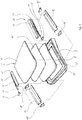
- FIG 2 an embodiment is schematically shown in an exploded view.
- Figure 2 shows the cover 1 existing of three layers; the upper layer 4 is the layer lying flush with the outside of the fixed roof 3 of the vehicle and is usually made of glass.
- the lower layer 4" is a layer which may be made of glass, but it is also conceivable that this layer is made of plastic such as PMMA or PC.
- the layer in between the upper layer 4 and the lower layer 4" is an intermediate layer 4' capable of adhering the lower layer 4" to the upper layer 4, usually this layer is a PVB layer or a PET layer.
- the upper layer 4 seen in plan-view is larger compared to the lower layer 4" and as such the upper layer 4 extends a certain distance over the edge 6 of the lower layer 4", whereas the intermediate layer 4' has substantially the same size as the lower layer 4".
- the circumferential edge 24 of the cover 1, 1' is made of an encapsulation material 7, such as PU or PVC. It is conceivable that the edge of only the upper layer 4 is equipped with encapsulation material 7 however in the embodiment in figure 2 the encapsulation material 7 surrounds the edges of both the upper and the lower layer 4, 4".
- Figure 2 further shows a light device 10 comprising a light source 11, a light guide 12 in the form of a bundle of light fibres 13.
- the light fibres 13 are equipped with a first connector 14 at a first end of the bundle of light fibres 13 and a second connector 15 at a second end of the bundle of light fibres 13.
- the first connector 14, when in assembled state in the open roof construction is positioned opposite and in close vicinity of the light source 11, such that light emitting of the light source 11 enters each of the light fibres 13 collected in the first connector 14.
- Such first connector 14 may be a plastic connector having a circular shape or another suitable shape, for instance a square shape.
- the shape of the first connector 14 should be made such that the bundle of fibres 13 is packed closely to each other to reduce the frontal surface of the first connector 14 and to have an optimum shape of the packed light fibres 13 for receiving the light emitted by the light source 11.
- the second connector 15, when assembled in the open roof construction is positioned along the edge 6 of a light emitting layer 5.
- the light emitting layer 5 is the lower layer 4".
- the second connector 15 can be made of plastic and has an elongated rectangular shape, whereby each of the fibres 13 is fixed in the second connector 15 at distances X with regard to each other.
- the light fibres 13 are fixed in the second connector 15 by means of moulding the light fibres 13 into the connector 15 during the moulding process of the connector. It is also conceivable that the light fibres 13 are fixed by a gluing operation into the second connector 15.
- the bundle of light fibres 13 extending from the first connector 14 towards the second connector 15 is grouped together in a bundle extending in a longitudinal direction along the longitudinal edge 6 of the light emitting layer 5.
- Each fibre 13 of the bundle that is fixed in the second connector 15 branches of the bundle towards the second connector 15.
- the light source 11 is positioned forward of the first connector 14 seen in longitudinal direction. From a point of view of space this may be advantageous however it may be conceivable that the light source 11 is positioned rearward of the first connector 14.
- the light emitting layer 5 is the lower layer 4".
- the light emitting layer 5 is capable of emitting light into the interior space 9 of the vehicle. As can be observed in fig.
- a protective unit 16 whereby the light device 10 partly is surrounded by the protective unit 16 and the layers 4, 4', 4" of the cover 1, 1'.
- this protective unit 16 is reinforcement 19 of the cover 1, 1' also shown in fig. 5 .
- Such reinforcement 19 is used to reinforce the cover 1, 1' to reduce the deflection of the cover 1, 1' in the open roof construction during driving conditions of the vehicle.
- Such reinforcements 19 may be made of metal.
- the protective unit 16 is open at a first end and at an opposite second end.
- a first and second plug 19', 19" are placed in the openings create by the first and second end of the reinforcement 19 and the inside of the layers 4, 4', 4" of the cover 1, 1'.
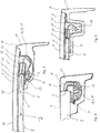
- a cross-sectional view is shown according to line III-III in fig. 2 , wherein the cover 1 is shown having an upper and a lower layer 4, 4" and whereby the lower layer 4" is connected to the upper layer 4 by means of an adherence layer for instance a PVB layer which is the intermediate layer 4'.
- the second connector 15 is mounted perpendicularly to the edge surface 6 of the lower layer 4", which is the light emitting layer 5 in this embodiment.
- the second connector 15 is fixed with its upper side to the lower edge of the upper layer 4 by means of a double sided tape 21 or the like.
- the second connector 15 is supported by a support bracket 23.
- the second connector 15 may also be adhered to the support bracket 23 by a double sided tape 21 or the like (not shown in fig. 3 ).
- the bundle of light fibres 13 extending from the first connector 14 towards the second connector 15 are grouped together in a bundle extending in a longitudinal direction along the longitudinal edge 6 of the light emitting layer 5.
- Each fibre 13 of the bundle that is fixed in the second connector 15 branches of the bundle of light fibres 13 towards the second connector 15, whereby a minimum radius of the fibre is maintained of approximately 30 mm.
- the bundle of light fibres 13 in the embodiment of fig. 3 is protected by a protective unit 16 in the form of a protection sleeve 17 or a protection foil 18.
- Such a sleeve 17 or foil 18 is made of a thin plastic layer.
- the protection sleeve 17 or foil 18 is connected (for instance by means of a double sided tape 21, not shown in fig. 3 ) to either of the inner layer 4", the support bracket 23, the inner face of the upper layer 4.
- the light emitting layer 5 may be equipped with means 28 for coupling out the light, which emit light into the direction of interior space 9 via main surface 8. It may be conceivable that the means 28 for coupling out the light are particles inside the light emitting layer 5 or it may be a print of ink or paint, for instance on the upper face of the light emitting layer 5 which emits light into the direction of the interior space 9.
- the embodiments in figs. 4, 5 , 6, 7 , 8 and 9 comprises likewise means 28 for coupling out the light (not shown) in the respective light emitting layers 5 and are thus also capable of emitting light towards the interior space 9.
- the second connector 15 in this embodiment is attached to the light emitting layer 5 of a cover 1 having only one layer 4.
- the second connector 15 has a shape such that it is fixed by means of a double sided tape 21 to the lower face of the light emitting layer 5 and that the end of the light fibres 13 are positioned adjacent to the edge surface 6 of the light emitting layer 5.
- the protective unit 16 here is a sleeve 17 or a foil 18 which is attached to the second connector 15 by for instance double sided tape 21 (not shown) which protects the bundle of light fibres 13 from direct contact with the encapsulation material 7.
- the second connector 15 is clipped by means of a clip fixing 22 to the support bracket 23.
- the support bracket 23 is connected to the lower face of a single layered cover 1 by means of for instance double sided tape 21.
- the encapsulation material 7 is only a small portion which is attached only to the light emitting layer 5 of the cover 1.
- the bundle of light fibres 13 is supported and fixed at regular distances along the longitudinal edge 6 of the light emitting layer 5 by means of clip fixings 27, the latter which are connected or clipped into the support bracket 23.
- the second connector 15 is connected to a support bracket 23 by means of for instance double sided tape 21.
- the support bracket 23 is attached to the lower face of the light emitting layer 5.
- the second connector 15 comprises a connector base part for fixing the light fibres 13 at regular distances X and a protective unit 16 which is in this embodiment a protector cover 25 being connected to the connector part by means of a film hinge 26.
- the protector cover 25 is further being clipped to a protruding part of the connector base part.
- the encapsulation material 7 in this embodiment surrounds the second connector 15, the support bracket 23 and part of the edge 6 of the light emitting layer 5.
- the light fibres 13 are protected by means of the protector cover 25 against the encapsulation material 7.
- the second connector 15 is fixed in between the support bracket 23 and the inner face of the upper layer 4 of the cover 1, by means of a clip fixing 22 integrated to the body of the second connector 15.
- the second connector 15 is fixed to the lower face of the lower layer 4" and the fibres 13 fixed in the second connector 15 are perpendicularly facing a light emitting layer 5 which is the intermediate layer 4' in this embodiment.
- the second connector 15 may be additionally fixed to the inner face of the upper layer 4.
- the light fibres 13 are positioned in the body of the second connector 15 such that the upper surface of the fibres 13 are exposed and engage the lower face of the upper layer 4, such as is schematically shown in fig. 9b .
- the light fibres 13 are protected by a protective unit 16, which may be a sleeve 17 or a foil 18, which is fixed by means of a double sided tape 21 against the lower face of the lower layer 4" and the lower face of the upper layer 4.
- the surplus length of the light fibre 13 may be cut off along the surface of the body of the second connector 15 in fig. 11b .
- the second connector 15 may than be ready for further preparation of guidance of the light fibres 13 see fig. 11c , in which distance X is drawn which is measured from centreline to centreline of each of the fibres mounted in the second connector 15.
- Next step is guiding the fibres 13 along the longitudinal length of the second connector 15 to one longitudinal end of the second connector 15 and whereby then afterwards the protector cover 25 may be closed to cover the light fibres 13 as is shown in fig. 11 d.
Landscapes
- Engineering & Computer Science (AREA)
- Mechanical Engineering (AREA)
- Arrangements Of Lighting Devices For Vehicle Interiors, Mounting And Supporting Thereof, Circuits Therefore (AREA)
- Light Guides In General And Applications Therefor (AREA)
Abstract
Description
- The invention relates to an open roof construction for a vehicle, comprising at least one cover capable of closing an opening in a fixed roof of the vehicle, the at least one cover comprising a light emitting layer capable of guiding light from a longitudinal edge of the light emitting layer, substantially parallel to a longitudinal direction of the vehicle, towards a main surface and capable of emitting light from a main surface of the light emitting layer towards an interior space of the vehicle, the cover further comprising a light device for emitting light into the light emitting layer, the light device comprising at least one light source and a light guide for guiding the light from the light source to the edge of the light emitting layer.
- Such an open roof construction is known from
DE102012109900-A1 and comprises a cover having an outer layer of glass, and an inner layer connected by means of an adhesive foil to the inner face of the outer panel. A light source is placed along the longitudinal edge of the inner layer. The light source emits light into the inner layer. The layer further comprises means for coupling out the light towards a direction of the interior of the vehicle. Although the document does not specify the nature of the light source, it could be understood that the light source is a series of LED's extending along the longitudinal edge of the inner layer. - Another open roof construction is known from
US2015/0175064-A1 comprising a covering device which can be wound up onto a winding up device. A waveguide extends along a longitudinal edge of the covering device, when the covering device closes below an opening in the vehicle roof. It is known that such a waveguide, also known as light guide is capable of guiding light from one end to another end of the light guide. However such light guide is equipped with means for coupling out light perpendicularly to the light guide. The guidance of light and the coupling out of light leads to loss of light to directions where the light should not travel, generating a lower light efficiency. This causes an unequal light pattern measured along the light emitting surface of the light guide. - In view of above it is object of the present invention to provide an improved open roof construction having a light device with an improved light pattern against low costs.
- In accordance with the present invention the open roof construction is characterized in that the light guide is formed by a bundle of light fibres existing of several light fibres. As such each light fibre of the bundle of light fibres guides an equal amount of light from a light source to the area to be lighted. The light is guided inside the light fibre, and just a very small fraction of light may be lost on the way. The high efficiency of transporting the light from one end to another is basically due to the so called cladding around the core of the fibre. The amount of light emitted at the end of each of the light fibres is equal to the human eye, when comparing the light emission from each fibre. As such this invention involves a solution for supplying an equal light pattern. Such an equal light pattern may be obtained by using an array of LED's positioned adjacent to each other however such a multitude of LED's is rather cost full. And so the present invention offers a solution for an equal light pattern against low costs.
- In one embodiment the light emitting layer may be layer of glass or a plastic layer, and the light emitting layer may be either of an upper layer, an intermediate layer or a lower layer of the cover. The invention can be applied to a cover having at least one layer. For instance it can be applied to a cover with a single glass layer or of a typical double glass layer with an adhesive layer in between which is known as a laminated glass panel or cover. It is also conceivable that the light emitting layer is a thin foil layer in between two glass sheets. Also it is conceivable that the at least one layer is a plastic layer for instance made of Polycarbonate or PMMA.
- In another embodiment each of the light fibres of the bundle of light fibres at a first end are accumulated closely together and are fixed in a first connector and wherein the first connector is positioned opposite to the light emitting surface of the light source such that the light from the light source is able to enter the light fibres. The light source, which may be a LED, emits light into the first connector, in which all of the light fibres are closely packed together in such a way that the light emitted by the light source enters the light fibres equally. As such it is possible to receive light by all of the closely packed light fibres. This means that the surface of the connector may not be too large such that the outer light fibres do not receive enough of the emitted light and that a maximum of light fibres in the range of 400 light fibres can be connected in the first connector depending on the thickness of the light fibres.
- In yet another embodiment wherein each of the light fibres of the bundle of light fibres, at a second end are fixed at distances X adjacent to each other in a second connector for holding the second end of the light fibres in a perpendicular direction with regard to the longitudinal edge of the light emitting layer to enable the light from the light fibres to enter the edge of the light emitting layer. The second connector holds each of the light fibres adjacent to each other at a certain distance X. The light fibres are directed perpendicularly to the longitudinal edge of the light emitting layer by means of the second connector. Light emitting from the fibres may enter the light emitting layer. It is important for the light efficiency that light enters the light emitting layer perpendicularly to its main surface. The distance X between the light fibres lies within a range of 0,125 mm. and 50 mm. and this is proved to be an optimum distance with regard to the light pattern. In case X is chosen larger than 50 mm, the light pattern will turn to be disrupted or intermittent. In case X is chosen in a smaller range towards 0,125 mm, the consequence may be that more light sources are needed to emit light into a same length of the longitudinal edge of the light emitting layer.
- In another embodiment the light fibres are either of glass material or of PMMA, and wherein the diameter of the fibres lie in the range of larger than 0,125 mm for glass fibres or larger than 0,25 for PMMA. Depending on the packaging space and financial reasons (PMMA fibres are cheaper than glass fibres) a choice can be made for either of glass or PMMA light fibres.
- In yet another embodiment a circumferential edge of the cover is made of encapsulation material. The cover may incorporate such material when it comprises not only one light emitting layer but also when it comprises more than one layer. As such it is conceivable that also the edges of all the layers are covered by the encapsulation material and it may also be conceivable that the light device as such is incorporated i.e. covered by the encapsulation material. On the other hand it is conceivable that not all of the layers have an edge which is covered by encapsulation material.
- In another embodiment the light fibres are protected in between the first and the second end in a protective unit for avoiding the fibres to be damaged, the protective unit either being a plastic protection sleeve, a protection foil, a cover reinforcement or a protector part attached to the second connector. But it is also conceivable that the bundle of light fibres in between the first and the second end is held by clip fixings attaching the bundle of fibres at intermittent distances to the cover. The multiple of light fibres in the bundle must be somehow protected or be guided in the area between the first and the second end of the light fibres, especially when the cover is equipped with edge of encapsulation material which will surround the light device, the fibres need to be protected by a protective unit from the encapsulation material during the manufacturing process. Filing the mould with encapsulation material involves the process of hot fluid material flowing from an inlet gate to fill the cavity under high pressure. This process may damage or move the fibres in an undesirable position. It is however also conceivable that the light fibres in the area between the first and second end are positioned by clips that locally attach the bundle of light fibres to the cover in cases where the encapsulation material does not surround the light device.
- In another embodiment the protective unit is a protector part, which is a protector cover connected to the second connector by means of a film hinge. As such the connector and the protector cover can be advantageously made of one injection moulding part. It is even conceivable that in the same injection moulding process of moulding connector and protector cover also the light fibres are moulded directly into the connector.
- In another embodiment the connector is connected by means of double sided tape or a clip fixing to either of the light emitting layer, the cover reinforcement, a support bracket attached to the cover or to another layer of the cover. It is conceivable that the connector is connected by double sided tape to the light emitting layer. This is most advantageous since the connector is directly coupled to the light emitting layer which gives a good accuracy with respect to the position of the second end of the light fibres in relation to the longitudinal edge of the light emitting layer. It is also conceivable that the connector is connected by means of a clip fixing to the cover reinforcement or the support bracket. Such a clip fixing enables an easier mounting of the connector to the cover.
- In another embodiment the light fibres extend with a radius R larger than 30 mm between the first and second end. Such limitation is required to avoid that light efficiency would be reduced due to the tendency of light to emit out of the fibre there where the radius of the fibre is too small.
- In all of the previous embodiments the light emitting layer further comprises means for coupling out the light such that the light emits from a main surface towards an interior space of the vehicle. Such means may be a printed pattern fabricated in or attached to the light emitting layer, the pattern causing light emitting in the direction towards the interior of the vehicle. Or it is conceivable that these means are particles inside the light emitting layer which are illuminated and emit light towards the interior.
- In another embodiment the open roof construction comprises two covers positioned adjacent to each other seen in a longitudinal direction of the vehicle and wherein each of the covers comprises a light emitting layer capable of guiding light from an longitudinal edge of the panel and capable of emitting light from a main surface into an interior space of the vehicle. In this embodiment both panels are equipped with light device which may emit light into the interior of the vehicle.
- Hereinafter the invention will be elucidated while referring to the drawing.
-
Figure 1 illustrates a part of a vehicle with adjacent positioned covers in a closed position. -
Figure 2 schematically illustrates an exploded view the cover, the light device and the protective unit. -
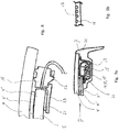
Figures 3 to 9a illustrate a sectional view taken along lines III-III infigure 1 , each showing a different embodiment. -
Figure 9b schematically illustrates a part of a view in direction of arrow P of the second connector. -
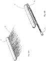
Figures 10a and 10b schematically show the light fibres and the second connector in two different stages of manufacturing. -
Figures 11a-e schematically show the second connector in various stages of manufacturing. - In
figure 1 a general lay-out of a vehicle comprising an open roof construction is illustrated. The vehicle comprises aroof opening 2 in afixed roof 3. In this case the open roof construction has twocovers 1, 1' placed adjacent to each other in a longitudinal direction of the vehicle. The frontal of the twocovers 1, 1' is an open able cover capable of closing and at least partly opening theroof opening 2 of the fixedroof 3. The second cover 1' placed rearward of thefront cover 1 may be a stationary cover closing the remaining part of theroof opening 2, however it is also conceivable that the second cover 1' is a movable cover. Alternatively it is also conceivable to have just one cover capable of closing and at least partly opening theroof opening 2. - In
figure 2 an embodiment is schematically shown in an exploded view.Figure 2 shows thecover 1 existing of three layers; theupper layer 4 is the layer lying flush with the outside of the fixedroof 3 of the vehicle and is usually made of glass. Thelower layer 4" is a layer which may be made of glass, but it is also conceivable that this layer is made of plastic such as PMMA or PC. The layer in between theupper layer 4 and thelower layer 4" is an intermediate layer 4' capable of adhering thelower layer 4" to theupper layer 4, usually this layer is a PVB layer or a PET layer. Theupper layer 4 seen in plan-view is larger compared to thelower layer 4" and as such theupper layer 4 extends a certain distance over theedge 6 of thelower layer 4", whereas the intermediate layer 4' has substantially the same size as thelower layer 4". Furthermore in this embodiment thecircumferential edge 24 of thecover 1, 1' is made of anencapsulation material 7, such as PU or PVC. It is conceivable that the edge of only theupper layer 4 is equipped withencapsulation material 7 however in the embodiment infigure 2 theencapsulation material 7 surrounds the edges of both the upper and thelower layer Figure 2 further shows alight device 10 comprising a light source 11, a light guide 12 in the form of a bundle oflight fibres 13. Thelight fibres 13 are equipped with afirst connector 14 at a first end of the bundle oflight fibres 13 and asecond connector 15 at a second end of the bundle oflight fibres 13. Thefirst connector 14, when in assembled state in the open roof construction is positioned opposite and in close vicinity of the light source 11, such that light emitting of the light source 11 enters each of thelight fibres 13 collected in thefirst connector 14. Suchfirst connector 14 may be a plastic connector having a circular shape or another suitable shape, for instance a square shape. The shape of thefirst connector 14 should be made such that the bundle offibres 13 is packed closely to each other to reduce the frontal surface of thefirst connector 14 and to have an optimum shape of the packedlight fibres 13 for receiving the light emitted by the light source 11. Thesecond connector 15, when assembled in the open roof construction is positioned along theedge 6 of alight emitting layer 5. In this embodiment offig. 2 thelight emitting layer 5 is thelower layer 4". Thesecond connector 15 can be made of plastic and has an elongated rectangular shape, whereby each of thefibres 13 is fixed in thesecond connector 15 at distances X with regard to each other. Thelight fibres 13 are fixed in thesecond connector 15 by means of moulding thelight fibres 13 into theconnector 15 during the moulding process of the connector. It is also conceivable that thelight fibres 13 are fixed by a gluing operation into thesecond connector 15. - The bundle of
light fibres 13 extending from thefirst connector 14 towards thesecond connector 15 is grouped together in a bundle extending in a longitudinal direction along thelongitudinal edge 6 of thelight emitting layer 5. Eachfibre 13 of the bundle that is fixed in thesecond connector 15 branches of the bundle towards thesecond connector 15. In the embodiment infig. 2 the light source 11 is positioned forward of thefirst connector 14 seen in longitudinal direction. From a point of view of space this may be advantageous however it may be conceivable that the light source 11 is positioned rearward of thefirst connector 14. In the embodiment infigure 2 thelight emitting layer 5 is thelower layer 4". Thelight emitting layer 5 is capable of emitting light into theinterior space 9 of the vehicle. As can be observed infig. 2 at least a part of thelight device 10 is protected by a protective unit 16, whereby thelight device 10 partly is surrounded by the protective unit 16 and thelayers cover 1, 1'. In the embodiment offig. 2 this protective unit 16 isreinforcement 19 of thecover 1, 1' also shown infig. 5 .Such reinforcement 19 is used to reinforce thecover 1, 1' to reduce the deflection of thecover 1, 1' in the open roof construction during driving conditions of the vehicle.Such reinforcements 19 may be made of metal. The protective unit 16 is open at a first end and at an opposite second end. To close the inside of thereinforcement 19 against entrance ofencapsulation material 7, a first andsecond plug 19', 19" are placed in the openings create by the first and second end of thereinforcement 19 and the inside of thelayers cover 1, 1'. - In
fig. 3 a cross-sectional view is shown according to line III-III infig. 2 , wherein thecover 1 is shown having an upper and alower layer lower layer 4" is connected to theupper layer 4 by means of an adherence layer for instance a PVB layer which is the intermediate layer 4'. Thesecond connector 15 is mounted perpendicularly to theedge surface 6 of thelower layer 4", which is thelight emitting layer 5 in this embodiment. Thesecond connector 15 is fixed with its upper side to the lower edge of theupper layer 4 by means of a doublesided tape 21 or the like. Thesecond connector 15 is supported by asupport bracket 23. Thesecond connector 15 may also be adhered to thesupport bracket 23 by a doublesided tape 21 or the like (not shown infig. 3 ). The bundle oflight fibres 13 extending from thefirst connector 14 towards thesecond connector 15 are grouped together in a bundle extending in a longitudinal direction along thelongitudinal edge 6 of thelight emitting layer 5. Eachfibre 13 of the bundle that is fixed in thesecond connector 15 branches of the bundle oflight fibres 13 towards thesecond connector 15, whereby a minimum radius of the fibre is maintained of approximately 30 mm. The bundle oflight fibres 13 in the embodiment offig. 3 is protected by a protective unit 16 in the form of a protection sleeve 17 or a protection foil 18. Such a sleeve 17 or foil 18 is made of a thin plastic layer. The protection sleeve 17 or foil 18 is connected (for instance by means of a doublesided tape 21, not shown infig. 3 ) to either of theinner layer 4", thesupport bracket 23, the inner face of theupper layer 4. As is shown infig.3 thelight fibres 13 emit light into thelight emitting layer 5. Thelight emitting layer 5 may be equipped withmeans 28 for coupling out the light, which emit light into the direction ofinterior space 9 viamain surface 8. It may be conceivable that themeans 28 for coupling out the light are particles inside thelight emitting layer 5 or it may be a print of ink or paint, for instance on the upper face of thelight emitting layer 5 which emits light into the direction of theinterior space 9. The embodiments infigs. 4, 5 ,6, 7 ,8 and 9 comprises likewise means 28 for coupling out the light (not shown) in the respectivelight emitting layers 5 and are thus also capable of emitting light towards theinterior space 9. - In
fig. 4 thesecond connector 15 in this embodiment is attached to thelight emitting layer 5 of acover 1 having only onelayer 4. Thesecond connector 15 has a shape such that it is fixed by means of a doublesided tape 21 to the lower face of thelight emitting layer 5 and that the end of thelight fibres 13 are positioned adjacent to theedge surface 6 of thelight emitting layer 5. The protective unit 16 here is a sleeve 17 or a foil 18 which is attached to thesecond connector 15 by for instance double sided tape 21 (not shown) which protects the bundle oflight fibres 13 from direct contact with theencapsulation material 7. - In
fig. 6 thesecond connector 15 is clipped by means of a clip fixing 22 to thesupport bracket 23. Thesupport bracket 23 is connected to the lower face of a singlelayered cover 1 by means of for instance double sidedtape 21. In this embodiment theencapsulation material 7 is only a small portion which is attached only to thelight emitting layer 5 of thecover 1. The bundle oflight fibres 13 is supported and fixed at regular distances along thelongitudinal edge 6 of thelight emitting layer 5 by means ofclip fixings 27, the latter which are connected or clipped into thesupport bracket 23. - In
fig. 7 thesecond connector 15 is connected to asupport bracket 23 by means of for instance double sidedtape 21. Thesupport bracket 23 is attached to the lower face of thelight emitting layer 5. In this embodiment thesecond connector 15 comprises a connector base part for fixing thelight fibres 13 at regular distances X and a protective unit 16 which is in this embodiment aprotector cover 25 being connected to the connector part by means of a film hinge 26. Theprotector cover 25 is further being clipped to a protruding part of the connector base part. Theencapsulation material 7 in this embodiment surrounds thesecond connector 15, thesupport bracket 23 and part of theedge 6 of thelight emitting layer 5. Thelight fibres 13 are protected by means of theprotector cover 25 against theencapsulation material 7. - In
fig. 8 thesecond connector 15 is fixed in between thesupport bracket 23 and the inner face of theupper layer 4 of thecover 1, by means of a clip fixing 22 integrated to the body of thesecond connector 15. - In
fig. 9a thesecond connector 15 is fixed to the lower face of thelower layer 4" and thefibres 13 fixed in thesecond connector 15 are perpendicularly facing alight emitting layer 5 which is the intermediate layer 4' in this embodiment. Thesecond connector 15 may be additionally fixed to the inner face of theupper layer 4. Thelight fibres 13 are positioned in the body of thesecond connector 15 such that the upper surface of thefibres 13 are exposed and engage the lower face of theupper layer 4, such as is schematically shown infig. 9b . Thelight fibres 13 are protected by a protective unit 16, which may be a sleeve 17 or a foil 18, which is fixed by means of a doublesided tape 21 against the lower face of thelower layer 4" and the lower face of theupper layer 4. - In
fig. 10a it is disclosed how thesecond connector 15 and thefibres 13 are orientated in such position that the connection between the fibres and thesecond connector 15 can be made in a manufacturing process. Infig. 10b thesecond connector 15, the bundle offibres 13 and thefirst connector 14 are shown in the orientation such as is obtained when thelight device 10 is assembled to thecover 1, 1'. - In
fig. 11a to 11d further details are shown of thesecond connector 15 of the embodiment offig. 7 . Infig. 11a it is shown that thelight fibres 13 are moulded into the body of thesecond connector 15 and that thelight fibres 13 extend with a surplus length outside the body of thesecond connector 15. This may be favourable in the production process to hold thelight fibres 13 in place at both ends and thus at either side of thesecond connector 15 during the moulding process of thesecond connector 15. - After the moulding process the surplus length of the
light fibre 13 may be cut off along the surface of the body of thesecond connector 15 infig. 11b . - The
second connector 15 may than be ready for further preparation of guidance of thelight fibres 13 seefig. 11c , in which distance X is drawn which is measured from centreline to centreline of each of the fibres mounted in thesecond connector 15. Next step is guiding thefibres 13 along the longitudinal length of thesecond connector 15 to one longitudinal end of thesecond connector 15 and whereby then afterwards theprotector cover 25 may be closed to cover thelight fibres 13 as is shown infig. 11 d. - The invention is not limited to the embodiments described before which may be varied widely within the scope of the invention as defined by the appending claims. For instance all embodiments shown in
figs. 3 to 9b may be incorporated in a rear cover 1'.
Claims (15)
- An open roof construction for a vehicle, comprising at least one cover (1, 1') capable of closing an opening (2) in a fixed roof (3) of the vehicle, the at least one cover (1, 1') comprising a light emitting layer (5) capable of guiding light from a longitudinal edge (6) of the light emitting layer (5), substantially parallel to a longitudinal direction of the vehicle, towards a main surface (8) and capable of emitting light from a main surface (8) of the light emitting layer (5) towards an interior space (9) of the vehicle, the cover (1, 1') further comprising a light device (10) for emitting light into the light emitting layer (5), the light device (10) comprising at least one light source (11) and a light guide (12) for guiding the light from the light source (11) to the edge (6) of the light emitting layer (5), characterized in that the light guide (12) is formed by a bundle of light fibres (13) existing of several light fibres.
- The open roof construction according to claim 1 wherein the light emitting layer (5) is a layer of glass or a plastic layer.
- The open roof construction according to claim 1 or 2 wherein the light emitting layer (5) is either of an upper layer (4), an intermediate layer (4'), a lower layer (4") of the cover (1, 1').
- The open roof construction according to one of the previous claims wherein each of the light fibres of the bundle of light fibres (13) at a first end are accumulated closely together and are fixed in a first connector (14) and wherein the first connector (14) is positioned opposite to the light emitting surface of the light source (11) such that the light from the light source (11) is able to enter the light fibres (13).
- The open roof construction according to one of the previous claims and wherein each of the light fibres of the bundle of light fibres (13), at a second end are fixed at distances X adjacent to each other in a second connector (15) for holding the second end of the light fibres (13) in a perpendicular direction with regard to the longitudinal edge (6) of the light emitting layer (5) to enable the light from the light fibres (13)to enter the edge (6) of the light emitting layer (5).
- The open roof construction according to claim 5 wherein the distances X between the light fibres (13) lies within a range of 0,125 mm. and 50 mm.
- The open roof construction according to one of the previous claims wherein the light fibres (13) are either of glass material or of PMMA, and wherein the diameter of the fibres (13) lie in the range of larger than 0,125 mm for glass fibres or larger than 0,25 for PMMA.
- The open roof construction according to one of the previous claims wherein the light fibres (13) are protected in between the first and the second end in a protective unit (16) for avoiding the fibres (13) to be damaged, the protective unit (16) either being a plastic protection sleeve (17), a protection foil (18), a cover reinforcement (19) or a protector part (20) attached to the second connector (15).
- The open roof construction according to claim 5 wherein the connector is connected by means of double sided tape (21) or a clip fixing (22) to either of the light emitting layer (5), the cover reinforcement (19), a support bracket (23) attached to the cover (1,1') or to another layer (4, 4', 4") of the cover (1, 1').
- The open roof construction according to one of the previous claims, wherein a circumferential edge 24 of the cover (1, 1') is made of encapsulation material (7).
- The open roof construction according to one of claims 1 to 7 wherein the bundle of light fibres (13) in between the first and the second end is held by clip fixings (27) attaching the bundle of fibres (13) at intermittent distances to the cover (1, 1').
- The open roof construction according to claim 8, wherein the protector part (20) is a protector cover (25) connected to the second connector (15) by means of a film hinge 26.
- The open roof construction according to one of claims 1 to 8, wherein the light fibres (13) extend with a radius R larger than 30 mm. between the first and second end.
- The open roof construction according to claim 1 or 2 wherein the light emitting layer (5) further comprises means (28) for coupling out the light such that the light emits from a main surface (8) towards an interior space (9) of the vehicle.
- The open roof construction according to claim 1 or 2 wherein the open roof construction comprises two covers (1, 1') positioned adjacent to each other seen in a longitudinal direction of the vehicle and wherein each of the covers (1, 1') comprises a light emitting layer (5) capable of guiding light from an longitudinal edge (6) of the panel and capable of emitting light from a main surface (8) into an interior space (9) of the vehicle.
Applications Claiming Priority (1)
| Application Number | Priority Date | Filing Date | Title |
|---|---|---|---|
| DE202017107507.9U DE202017107507U1 (en) | 2017-12-11 | 2017-12-11 | Open roof construction for a vehicle |
Publications (2)
| Publication Number | Publication Date |
|---|---|
| EP3495204A1 true EP3495204A1 (en) | 2019-06-12 |
| EP3495204B1 EP3495204B1 (en) | 2022-09-07 |
Family
ID=63878353
Family Applications (1)
| Application Number | Title | Priority Date | Filing Date |
|---|---|---|---|
| EP18200604.9A Active EP3495204B1 (en) | 2017-12-11 | 2018-10-16 | Open roof construction for a vehicle |
Country Status (4)
| Country | Link |
|---|---|
| US (1) | US10589666B2 (en) |
| EP (1) | EP3495204B1 (en) |
| CN (1) | CN109895689B (en) |
| DE (1) | DE202017107507U1 (en) |
Families Citing this family (5)
| Publication number | Priority date | Publication date | Assignee | Title |
|---|---|---|---|---|
| CN112644373B (en) * | 2019-10-10 | 2025-10-21 | 英纳法天窗系统集团有限公司 | Glass panel assembly for a vehicle roof |
| DE102020109338B3 (en) | 2020-04-03 | 2021-05-27 | Webasto SE | Vehicle window with light source and light guide layer |
| CN112498232B (en) * | 2020-11-26 | 2022-08-02 | 山东豪驰智能汽车有限公司 | LED lamp strip mounting structure on automobile glass |
| DE102022131551B4 (en) * | 2022-11-29 | 2024-07-25 | Webasto SE | Arrangement and method for producing an arrangement for a vehicle roof and vehicle roof for a motor vehicle |
| CN119527009B (en) * | 2024-12-13 | 2025-12-09 | 福耀玻璃工业集团股份有限公司 | Sunshade curtain assembly, glass assembly and vehicle |
Citations (9)
| Publication number | Priority date | Publication date | Assignee | Title |
|---|---|---|---|---|
| US5647658A (en) * | 1995-05-11 | 1997-07-15 | Ziadi; Bouchaib | Fiber-optic lighting system |
| KR20090115543A (en) * | 2008-05-02 | 2009-11-05 | 현대자동차주식회사 | Sunshade unit in panoramic sunroof with indirect lighting |
| DE102009039556A1 (en) * | 2008-09-01 | 2010-03-25 | Schott Ag | Illuminating system i.e. line- or surface illuminating system, for inner lining of motor vehicle, has fiber bundle arranged in enclosed plastic shroud in which side-emitting fibers are movable in axial direction against each other |
| DE102011016392A1 (en) * | 2011-04-08 | 2012-10-11 | GM Global Technology Operations LLC (n. d. Gesetzen des Staates Delaware) | Roof lighting for vehicle, has coupling area for illuminating vehicle interior, where roof lighting is extended in vehicle over large part of surface of vehicle roof, and illumination unit is provided with light source for generating light |
| FR2979412A1 (en) * | 2011-08-23 | 2013-03-01 | Faurecia Interieur Ind | Lighting device for illuminating frame of interior trim of vehicle, has optical fiber layer arranged in form of loop such that ends of each fiber of layer is illuminated with single light source and radiate light along optical fiber |
| FR3018742A1 (en) * | 2014-03-19 | 2015-09-25 | Peugeot Citroen Automobiles Sa | MOBILE LIGHTING PANEL AND LIGHTING OPENING ROOF SYSTEM |
| DE202015106738U1 (en) * | 2015-12-10 | 2016-01-11 | Webasto SE | Arrangement for a motor vehicle with a cover |
| DE202014009548U1 (en) * | 2014-12-03 | 2016-03-07 | Webasto SE | Guide rail of a covering device with a lighting device for a vehicle interior |
| FR3043025A1 (en) * | 2015-10-30 | 2017-05-05 | Peugeot Citroen Automobiles Sa | TRANSPARENT OR TRANSLUCENT PANEL OF MOTOR VEHICLE WITH LUMINOPHORIC OPTICAL ELEMENTS |
Family Cites Families (17)
| Publication number | Priority date | Publication date | Assignee | Title |
|---|---|---|---|---|
| DE19852593B4 (en) * | 1998-11-14 | 2006-03-30 | Daimlerchrysler Ag | Device for illuminating an interior and its use |
| DE10204359B4 (en) * | 2001-03-25 | 2005-05-04 | Webasto Ag | vehicle roof |
| DE10134641A1 (en) * | 2001-07-17 | 2003-05-22 | Arvinmeritor Gmbh | Sunroof for a vehicle |
| US20070160334A1 (en) * | 2006-01-10 | 2007-07-12 | Cobb Weston T | End-emitting fiber optic indicia for motor vehicles |
| JP2008074262A (en) * | 2006-09-21 | 2008-04-03 | Toyoda Gosei Co Ltd | Interior parts for vehicles |
| US8382516B2 (en) * | 2008-10-02 | 2013-02-26 | Thales Avionics, Inc. | Adaptable configuration plug in a vehicle entertainment system |
| DE102010045070A1 (en) * | 2010-09-10 | 2012-03-15 | Volkswagen Ag | Light assembly for use in vehicle, is provided with vehicle window and light source, where light source is arranged so that light emission is linked in vehicle window by light input |
| DE102011014263B4 (en) * | 2011-03-17 | 2014-03-27 | Audi Ag | Window device with lighting for a motor vehicle |
| FR2978379B1 (en) * | 2011-07-29 | 2014-03-14 | Saint Gobain | LIGHTING OF VEHICLE, MANUFACTURING |
| FR2991931B1 (en) | 2012-06-18 | 2015-01-09 | Webasto Systemes Carrosserie | OCCULTATION DEVICE HAVING A LIGHT SOURCE |
| DE102012109900B4 (en) | 2012-10-17 | 2015-10-15 | Bayerische Motoren Werke Aktiengesellschaft | vehicle glazing |
| CN102943975B (en) * | 2012-11-05 | 2015-11-25 | 深圳市华星光电技术有限公司 | Backlight module and display device |
| DE102014003527A1 (en) * | 2014-03-12 | 2015-09-17 | Diehl Aerospace Gmbh | Aircraft lighting device for the cabin of an aircraft and aircraft with the aircraft lighting device |
| DE102015106738A1 (en) * | 2015-04-30 | 2016-11-03 | Brodmann Technologies GmbH | Method for contactless assessment of the surface condition of a ball track of a ball screw |
| FR3040992B1 (en) * | 2015-09-11 | 2017-10-06 | Saint Gobain | LUMINOUS GLAZING OF VEHICLE AND ITS MANUFACTURE. |
| US10150352B2 (en) * | 2016-02-11 | 2018-12-11 | Ford Global Technologies, Llc | Illuminated window assemblies having light-diffusing elements |
| US10272832B2 (en) * | 2017-06-29 | 2019-04-30 | Ford Global Technologies, Llc | Lighting pipe integrated within sunroof trim ring |
-
2017
- 2017-12-11 DE DE202017107507.9U patent/DE202017107507U1/en active Active
-
2018
- 2018-10-16 EP EP18200604.9A patent/EP3495204B1/en active Active
- 2018-11-27 CN CN201811469169.6A patent/CN109895689B/en active Active
- 2018-12-07 US US16/213,372 patent/US10589666B2/en active Active
Patent Citations (9)
| Publication number | Priority date | Publication date | Assignee | Title |
|---|---|---|---|---|
| US5647658A (en) * | 1995-05-11 | 1997-07-15 | Ziadi; Bouchaib | Fiber-optic lighting system |
| KR20090115543A (en) * | 2008-05-02 | 2009-11-05 | 현대자동차주식회사 | Sunshade unit in panoramic sunroof with indirect lighting |
| DE102009039556A1 (en) * | 2008-09-01 | 2010-03-25 | Schott Ag | Illuminating system i.e. line- or surface illuminating system, for inner lining of motor vehicle, has fiber bundle arranged in enclosed plastic shroud in which side-emitting fibers are movable in axial direction against each other |
| DE102011016392A1 (en) * | 2011-04-08 | 2012-10-11 | GM Global Technology Operations LLC (n. d. Gesetzen des Staates Delaware) | Roof lighting for vehicle, has coupling area for illuminating vehicle interior, where roof lighting is extended in vehicle over large part of surface of vehicle roof, and illumination unit is provided with light source for generating light |
| FR2979412A1 (en) * | 2011-08-23 | 2013-03-01 | Faurecia Interieur Ind | Lighting device for illuminating frame of interior trim of vehicle, has optical fiber layer arranged in form of loop such that ends of each fiber of layer is illuminated with single light source and radiate light along optical fiber |
| FR3018742A1 (en) * | 2014-03-19 | 2015-09-25 | Peugeot Citroen Automobiles Sa | MOBILE LIGHTING PANEL AND LIGHTING OPENING ROOF SYSTEM |
| DE202014009548U1 (en) * | 2014-12-03 | 2016-03-07 | Webasto SE | Guide rail of a covering device with a lighting device for a vehicle interior |
| FR3043025A1 (en) * | 2015-10-30 | 2017-05-05 | Peugeot Citroen Automobiles Sa | TRANSPARENT OR TRANSLUCENT PANEL OF MOTOR VEHICLE WITH LUMINOPHORIC OPTICAL ELEMENTS |
| DE202015106738U1 (en) * | 2015-12-10 | 2016-01-11 | Webasto SE | Arrangement for a motor vehicle with a cover |
Also Published As
| Publication number | Publication date |
|---|---|
| US20190176691A1 (en) | 2019-06-13 |
| DE202017107507U1 (en) | 2019-03-12 |
| US10589666B2 (en) | 2020-03-17 |
| CN109895689A (en) | 2019-06-18 |
| EP3495204B1 (en) | 2022-09-07 |
| CN109895689B (en) | 2024-03-08 |
Similar Documents
| Publication | Publication Date | Title |
|---|---|---|
| EP3495204B1 (en) | Open roof construction for a vehicle | |
| US10060594B2 (en) | Light guiding device | |
| US10168021B2 (en) | Light guiding device | |
| CN108990414B (en) | Illuminated glazing unit | |
| US12233778B2 (en) | Transparent roof panel assembly for a vehicle roof | |
| US20140003076A1 (en) | Vehicular lamp and window unit | |
| CN111976849A (en) | Rear movable piece including embedded light-emitting device | |
| US7186012B2 (en) | Lighting element with a light emitting diode | |
| JP6593646B2 (en) | Vehicle lighting system | |
| US20160102833A1 (en) | Light emitting device and vehicle lamp | |
| EP3881004B1 (en) | Fiber optic panel having extended abrasion | |
| US12077100B2 (en) | Lighting device, lighting system, and motor vehicle with lighting system | |
| US20240418338A1 (en) | Optical module for a light-emitting device of a motor vehicle | |
| JP2005215596A (en) | Onboard light emission display device | |
| US12311840B2 (en) | Lighting device, interior trim assembly including the lighting device and method of manufacturing a trim assembly | |
| KR102797044B1 (en) | Decorative part with flat light guide | |
| JP7208205B2 (en) | Display device and display device manufacturing method | |
| CN100416315C (en) | Light guide system with sheet-like light-emitting elements | |
| CN105216689A (en) | For the assembly part of power actuated vehicle and the method for this assembly part of manufacture | |
| JP2014181006A (en) | Indoor lighting apparatus for vehicle | |
| EP4474694A1 (en) | A transparent roof panel assembly for a vehicle roof, and method of making it | |
| WO2015199812A1 (en) | Light guide with integrated icon | |
| CN222882875U (en) | Side-emitting optical fiber insert structure | |
| CN220576772U (en) | Glass panel assembly | |
| JP2014180936A (en) | Indoor lighting apparatus for vehicle |
Legal Events
| Date | Code | Title | Description |
|---|---|---|---|
| PUAI | Public reference made under article 153(3) epc to a published international application that has entered the european phase |
Free format text: ORIGINAL CODE: 0009012 |
|
| STAA | Information on the status of an ep patent application or granted ep patent |
Free format text: STATUS: THE APPLICATION HAS BEEN PUBLISHED |
|
| AK | Designated contracting states |
Kind code of ref document: A1 Designated state(s): AL AT BE BG CH CY CZ DE DK EE ES FI FR GB GR HR HU IE IS IT LI LT LU LV MC MK MT NL NO PL PT RO RS SE SI SK SM TR |
|
| AX | Request for extension of the european patent |
Extension state: BA ME |
|
| STAA | Information on the status of an ep patent application or granted ep patent |
Free format text: STATUS: REQUEST FOR EXAMINATION WAS MADE |
|
| 17P | Request for examination filed |
Effective date: 20191114 |
|
| RBV | Designated contracting states (corrected) |
Designated state(s): AL AT BE BG CH CY CZ DE DK EE ES FI FR GB GR HR HU IE IS IT LI LT LU LV MC MK MT NL NO PL PT RO RS SE SI SK SM TR |
|
| GRAP | Despatch of communication of intention to grant a patent |
Free format text: ORIGINAL CODE: EPIDOSNIGR1 |
|
| STAA | Information on the status of an ep patent application or granted ep patent |
Free format text: STATUS: GRANT OF PATENT IS INTENDED |
|
| INTG | Intention to grant announced |
Effective date: 20220307 |
|
| GRAJ | Information related to disapproval of communication of intention to grant by the applicant or resumption of examination proceedings by the epo deleted |
Free format text: ORIGINAL CODE: EPIDOSDIGR1 |
|
| STAA | Information on the status of an ep patent application or granted ep patent |
Free format text: STATUS: REQUEST FOR EXAMINATION WAS MADE |
|
| INTC | Intention to grant announced (deleted) | ||
| GRAP | Despatch of communication of intention to grant a patent |
Free format text: ORIGINAL CODE: EPIDOSNIGR1 |
|
| STAA | Information on the status of an ep patent application or granted ep patent |
Free format text: STATUS: GRANT OF PATENT IS INTENDED |
|
| GRAS | Grant fee paid |
Free format text: ORIGINAL CODE: EPIDOSNIGR3 |
|
| GRAA | (expected) grant |
Free format text: ORIGINAL CODE: 0009210 |
|
| STAA | Information on the status of an ep patent application or granted ep patent |
Free format text: STATUS: THE PATENT HAS BEEN GRANTED |
|
| INTG | Intention to grant announced |
Effective date: 20220728 |
|
| AK | Designated contracting states |
Kind code of ref document: B1 Designated state(s): AL AT BE BG CH CY CZ DE DK EE ES FI FR GB GR HR HU IE IS IT LI LT LU LV MC MK MT NL NO PL PT RO RS SE SI SK SM TR |
|
| REG | Reference to a national code |
Ref country code: GB Ref legal event code: FG4D |
|
| REG | Reference to a national code |
Ref country code: CH Ref legal event code: EP Ref country code: AT Ref legal event code: REF Ref document number: 1516776 Country of ref document: AT Kind code of ref document: T Effective date: 20220915 |
|
| REG | Reference to a national code |
Ref country code: IE Ref legal event code: FG4D |
|
| REG | Reference to a national code |
Ref country code: DE Ref legal event code: R096 Ref document number: 602018040262 Country of ref document: DE |
|
| REG | Reference to a national code |
Ref country code: LT Ref legal event code: MG9D |
|
| REG | Reference to a national code |
Ref country code: NL Ref legal event code: MP Effective date: 20220907 |
|
| PG25 | Lapsed in a contracting state [announced via postgrant information from national office to epo] |
Ref country code: SE Free format text: LAPSE BECAUSE OF FAILURE TO SUBMIT A TRANSLATION OF THE DESCRIPTION OR TO PAY THE FEE WITHIN THE PRESCRIBED TIME-LIMIT Effective date: 20220907 Ref country code: RS Free format text: LAPSE BECAUSE OF FAILURE TO SUBMIT A TRANSLATION OF THE DESCRIPTION OR TO PAY THE FEE WITHIN THE PRESCRIBED TIME-LIMIT Effective date: 20220907 Ref country code: NO Free format text: LAPSE BECAUSE OF FAILURE TO SUBMIT A TRANSLATION OF THE DESCRIPTION OR TO PAY THE FEE WITHIN THE PRESCRIBED TIME-LIMIT Effective date: 20221207 Ref country code: LV Free format text: LAPSE BECAUSE OF FAILURE TO SUBMIT A TRANSLATION OF THE DESCRIPTION OR TO PAY THE FEE WITHIN THE PRESCRIBED TIME-LIMIT Effective date: 20220907 Ref country code: LT Free format text: LAPSE BECAUSE OF FAILURE TO SUBMIT A TRANSLATION OF THE DESCRIPTION OR TO PAY THE FEE WITHIN THE PRESCRIBED TIME-LIMIT Effective date: 20220907 Ref country code: FI Free format text: LAPSE BECAUSE OF FAILURE TO SUBMIT A TRANSLATION OF THE DESCRIPTION OR TO PAY THE FEE WITHIN THE PRESCRIBED TIME-LIMIT Effective date: 20220907 |
|
| REG | Reference to a national code |
Ref country code: AT Ref legal event code: MK05 Ref document number: 1516776 Country of ref document: AT Kind code of ref document: T Effective date: 20220907 |
|
| PG25 | Lapsed in a contracting state [announced via postgrant information from national office to epo] |
Ref country code: HR Free format text: LAPSE BECAUSE OF FAILURE TO SUBMIT A TRANSLATION OF THE DESCRIPTION OR TO PAY THE FEE WITHIN THE PRESCRIBED TIME-LIMIT Effective date: 20220907 Ref country code: GR Free format text: LAPSE BECAUSE OF FAILURE TO SUBMIT A TRANSLATION OF THE DESCRIPTION OR TO PAY THE FEE WITHIN THE PRESCRIBED TIME-LIMIT Effective date: 20221208 |
|
| PG25 | Lapsed in a contracting state [announced via postgrant information from national office to epo] |
Ref country code: SM Free format text: LAPSE BECAUSE OF FAILURE TO SUBMIT A TRANSLATION OF THE DESCRIPTION OR TO PAY THE FEE WITHIN THE PRESCRIBED TIME-LIMIT Effective date: 20220907 Ref country code: RO Free format text: LAPSE BECAUSE OF FAILURE TO SUBMIT A TRANSLATION OF THE DESCRIPTION OR TO PAY THE FEE WITHIN THE PRESCRIBED TIME-LIMIT Effective date: 20220907 Ref country code: PT Free format text: LAPSE BECAUSE OF FAILURE TO SUBMIT A TRANSLATION OF THE DESCRIPTION OR TO PAY THE FEE WITHIN THE PRESCRIBED TIME-LIMIT Effective date: 20230109 Ref country code: ES Free format text: LAPSE BECAUSE OF FAILURE TO SUBMIT A TRANSLATION OF THE DESCRIPTION OR TO PAY THE FEE WITHIN THE PRESCRIBED TIME-LIMIT Effective date: 20220907 Ref country code: CZ Free format text: LAPSE BECAUSE OF FAILURE TO SUBMIT A TRANSLATION OF THE DESCRIPTION OR TO PAY THE FEE WITHIN THE PRESCRIBED TIME-LIMIT Effective date: 20220907 Ref country code: AT Free format text: LAPSE BECAUSE OF FAILURE TO SUBMIT A TRANSLATION OF THE DESCRIPTION OR TO PAY THE FEE WITHIN THE PRESCRIBED TIME-LIMIT Effective date: 20220907 |
|
| PG25 | Lapsed in a contracting state [announced via postgrant information from national office to epo] |
Ref country code: SK Free format text: LAPSE BECAUSE OF FAILURE TO SUBMIT A TRANSLATION OF THE DESCRIPTION OR TO PAY THE FEE WITHIN THE PRESCRIBED TIME-LIMIT Effective date: 20220907 Ref country code: PL Free format text: LAPSE BECAUSE OF FAILURE TO SUBMIT A TRANSLATION OF THE DESCRIPTION OR TO PAY THE FEE WITHIN THE PRESCRIBED TIME-LIMIT Effective date: 20220907 Ref country code: IS Free format text: LAPSE BECAUSE OF FAILURE TO SUBMIT A TRANSLATION OF THE DESCRIPTION OR TO PAY THE FEE WITHIN THE PRESCRIBED TIME-LIMIT Effective date: 20230107 Ref country code: EE Free format text: LAPSE BECAUSE OF FAILURE TO SUBMIT A TRANSLATION OF THE DESCRIPTION OR TO PAY THE FEE WITHIN THE PRESCRIBED TIME-LIMIT Effective date: 20220907 |
|
| REG | Reference to a national code |
Ref country code: CH Ref legal event code: PL |
|
| REG | Reference to a national code |
Ref country code: DE Ref legal event code: R097 Ref document number: 602018040262 Country of ref document: DE |
|
| REG | Reference to a national code |
Ref country code: BE Ref legal event code: MM Effective date: 20221031 |
|
| PG25 | Lapsed in a contracting state [announced via postgrant information from national office to epo] |
Ref country code: NL Free format text: LAPSE BECAUSE OF FAILURE TO SUBMIT A TRANSLATION OF THE DESCRIPTION OR TO PAY THE FEE WITHIN THE PRESCRIBED TIME-LIMIT Effective date: 20220907 Ref country code: MC Free format text: LAPSE BECAUSE OF FAILURE TO SUBMIT A TRANSLATION OF THE DESCRIPTION OR TO PAY THE FEE WITHIN THE PRESCRIBED TIME-LIMIT Effective date: 20220907 Ref country code: LU Free format text: LAPSE BECAUSE OF NON-PAYMENT OF DUE FEES Effective date: 20221016 Ref country code: AL Free format text: LAPSE BECAUSE OF FAILURE TO SUBMIT A TRANSLATION OF THE DESCRIPTION OR TO PAY THE FEE WITHIN THE PRESCRIBED TIME-LIMIT Effective date: 20220907 |
|
| PLBE | No opposition filed within time limit |
Free format text: ORIGINAL CODE: 0009261 |
|
| STAA | Information on the status of an ep patent application or granted ep patent |
Free format text: STATUS: NO OPPOSITION FILED WITHIN TIME LIMIT |
|
| PG25 | Lapsed in a contracting state [announced via postgrant information from national office to epo] |
Ref country code: LI Free format text: LAPSE BECAUSE OF NON-PAYMENT OF DUE FEES Effective date: 20221031 Ref country code: DK Free format text: LAPSE BECAUSE OF FAILURE TO SUBMIT A TRANSLATION OF THE DESCRIPTION OR TO PAY THE FEE WITHIN THE PRESCRIBED TIME-LIMIT Effective date: 20220907 Ref country code: CH Free format text: LAPSE BECAUSE OF NON-PAYMENT OF DUE FEES Effective date: 20221031 |
|
| 26N | No opposition filed |
Effective date: 20230608 |
|
| GBPC | Gb: european patent ceased through non-payment of renewal fee |
Effective date: 20221207 |
|
| PG25 | Lapsed in a contracting state [announced via postgrant information from national office to epo] |
Ref country code: SI Free format text: LAPSE BECAUSE OF FAILURE TO SUBMIT A TRANSLATION OF THE DESCRIPTION OR TO PAY THE FEE WITHIN THE PRESCRIBED TIME-LIMIT Effective date: 20220907 |
|
| PG25 | Lapsed in a contracting state [announced via postgrant information from national office to epo] |
Ref country code: BE Free format text: LAPSE BECAUSE OF NON-PAYMENT OF DUE FEES Effective date: 20221031 |
|
| PG25 | Lapsed in a contracting state [announced via postgrant information from national office to epo] |
Ref country code: IE Free format text: LAPSE BECAUSE OF NON-PAYMENT OF DUE FEES Effective date: 20221016 Ref country code: GB Free format text: LAPSE BECAUSE OF NON-PAYMENT OF DUE FEES Effective date: 20221207 |
|
| PG25 | Lapsed in a contracting state [announced via postgrant information from national office to epo] |
Ref country code: HU Free format text: LAPSE BECAUSE OF FAILURE TO SUBMIT A TRANSLATION OF THE DESCRIPTION OR TO PAY THE FEE WITHIN THE PRESCRIBED TIME-LIMIT; INVALID AB INITIO Effective date: 20181016 |
|
| PG25 | Lapsed in a contracting state [announced via postgrant information from national office to epo] |
Ref country code: CY Free format text: LAPSE BECAUSE OF FAILURE TO SUBMIT A TRANSLATION OF THE DESCRIPTION OR TO PAY THE FEE WITHIN THE PRESCRIBED TIME-LIMIT Effective date: 20220907 |
|
| PG25 | Lapsed in a contracting state [announced via postgrant information from national office to epo] |
Ref country code: MK Free format text: LAPSE BECAUSE OF FAILURE TO SUBMIT A TRANSLATION OF THE DESCRIPTION OR TO PAY THE FEE WITHIN THE PRESCRIBED TIME-LIMIT Effective date: 20220907 Ref country code: IT Free format text: LAPSE BECAUSE OF FAILURE TO SUBMIT A TRANSLATION OF THE DESCRIPTION OR TO PAY THE FEE WITHIN THE PRESCRIBED TIME-LIMIT Effective date: 20220907 |
|
| PG25 | Lapsed in a contracting state [announced via postgrant information from national office to epo] |
Ref country code: TR Free format text: LAPSE BECAUSE OF FAILURE TO SUBMIT A TRANSLATION OF THE DESCRIPTION OR TO PAY THE FEE WITHIN THE PRESCRIBED TIME-LIMIT Effective date: 20220907 |
|
| PG25 | Lapsed in a contracting state [announced via postgrant information from national office to epo] |
Ref country code: BG Free format text: LAPSE BECAUSE OF FAILURE TO SUBMIT A TRANSLATION OF THE DESCRIPTION OR TO PAY THE FEE WITHIN THE PRESCRIBED TIME-LIMIT Effective date: 20220907 |
|
| PG25 | Lapsed in a contracting state [announced via postgrant information from national office to epo] |
Ref country code: MT Free format text: LAPSE BECAUSE OF FAILURE TO SUBMIT A TRANSLATION OF THE DESCRIPTION OR TO PAY THE FEE WITHIN THE PRESCRIBED TIME-LIMIT Effective date: 20220907 |
|
| PGFP | Annual fee paid to national office [announced via postgrant information from national office to epo] |
Ref country code: DE Payment date: 20251029 Year of fee payment: 8 |
|
| PGFP | Annual fee paid to national office [announced via postgrant information from national office to epo] |
Ref country code: FR Payment date: 20251027 Year of fee payment: 8 |