EP3495163A1 - Tire steel cord and pneumatic tire using same - Google Patents
Tire steel cord and pneumatic tire using same Download PDFInfo
- Publication number
- EP3495163A1 EP3495163A1 EP17836859.3A EP17836859A EP3495163A1 EP 3495163 A1 EP3495163 A1 EP 3495163A1 EP 17836859 A EP17836859 A EP 17836859A EP 3495163 A1 EP3495163 A1 EP 3495163A1
- Authority
- EP
- European Patent Office
- Prior art keywords
- filaments
- steel cord
- core
- sheath
- tire
- Prior art date
- Legal status (The legal status is an assumption and is not a legal conclusion. Google has not performed a legal analysis and makes no representation as to the accuracy of the status listed.)
- Granted
Links
Images
Classifications
-
- B—PERFORMING OPERATIONS; TRANSPORTING
- B60—VEHICLES IN GENERAL
- B60C—VEHICLE TYRES; TYRE INFLATION; TYRE CHANGING; CONNECTING VALVES TO INFLATABLE ELASTIC BODIES IN GENERAL; DEVICES OR ARRANGEMENTS RELATED TO TYRES
- B60C9/00—Reinforcements or ply arrangement of pneumatic tyres
- B60C9/0007—Reinforcements made of metallic elements, e.g. cords, yarns, filaments or fibres made from metal
-
- B—PERFORMING OPERATIONS; TRANSPORTING
- B60—VEHICLES IN GENERAL
- B60C—VEHICLE TYRES; TYRE INFLATION; TYRE CHANGING; CONNECTING VALVES TO INFLATABLE ELASTIC BODIES IN GENERAL; DEVICES OR ARRANGEMENTS RELATED TO TYRES
- B60C9/00—Reinforcements or ply arrangement of pneumatic tyres
-
- D—TEXTILES; PAPER
- D07—ROPES; CABLES OTHER THAN ELECTRIC
- D07B—ROPES OR CABLES IN GENERAL
- D07B1/00—Constructional features of ropes or cables
- D07B1/06—Ropes or cables built-up from metal wires, e.g. of section wires around a hemp core
-
- D—TEXTILES; PAPER
- D07—ROPES; CABLES OTHER THAN ELECTRIC
- D07B—ROPES OR CABLES IN GENERAL
- D07B1/00—Constructional features of ropes or cables
- D07B1/06—Ropes or cables built-up from metal wires, e.g. of section wires around a hemp core
- D07B1/0606—Reinforcing cords for rubber or plastic articles
- D07B1/062—Reinforcing cords for rubber or plastic articles the reinforcing cords being characterised by the strand configuration
-
- D—TEXTILES; PAPER
- D07—ROPES; CABLES OTHER THAN ELECTRIC
- D07B—ROPES OR CABLES IN GENERAL
- D07B2201/00—Ropes or cables
- D07B2201/20—Rope or cable components
- D07B2201/2001—Wires or filaments
- D07B2201/2006—Wires or filaments characterised by a value or range of the dimension given
-
- D—TEXTILES; PAPER
- D07—ROPES; CABLES OTHER THAN ELECTRIC
- D07B—ROPES OR CABLES IN GENERAL
- D07B2201/00—Ropes or cables
- D07B2201/20—Rope or cable components
- D07B2201/2015—Strands
- D07B2201/2024—Strands twisted
- D07B2201/2029—Open winding
- D07B2201/203—Cylinder winding, i.e. S/Z or Z/S
-
- D—TEXTILES; PAPER
- D07—ROPES; CABLES OTHER THAN ELECTRIC
- D07B—ROPES OR CABLES IN GENERAL
- D07B2201/00—Ropes or cables
- D07B2201/20—Rope or cable components
- D07B2201/2047—Cores
- D07B2201/2051—Cores characterised by a value or range of the dimension given
-
- D—TEXTILES; PAPER
- D07—ROPES; CABLES OTHER THAN ELECTRIC
- D07B—ROPES OR CABLES IN GENERAL
- D07B2201/00—Ropes or cables
- D07B2201/20—Rope or cable components
- D07B2201/2047—Cores
- D07B2201/2052—Cores characterised by their structure
- D07B2201/2059—Cores characterised by their structure comprising wires
- D07B2201/2061—Cores characterised by their structure comprising wires resulting in a twisted structure
-
- D—TEXTILES; PAPER
- D07—ROPES; CABLES OTHER THAN ELECTRIC
- D07B—ROPES OR CABLES IN GENERAL
- D07B2401/00—Aspects related to the problem to be solved or advantage
- D07B2401/20—Aspects related to the problem to be solved or advantage related to ropes or cables
- D07B2401/206—Improving radial flexibility
-
- D—TEXTILES; PAPER
- D07—ROPES; CABLES OTHER THAN ELECTRIC
- D07B—ROPES OR CABLES IN GENERAL
- D07B2401/00—Aspects related to the problem to be solved or advantage
- D07B2401/20—Aspects related to the problem to be solved or advantage related to ropes or cables
- D07B2401/208—Enabling filler penetration
Definitions
- the present invention relates to a tire steel cord, and a pneumatic tire including the same (hereinafter, also simply referred to as "steel cord” and “tire”, respectively). More particularly, the present invention relates to: a tire steel cord having not only excellent cutting resistance and corrosion resistance but also excellent processability in plant; and a pneumatic tire including the same.
- Patent Document 1 proposes a steel cord which includes a core composed of one to three steel filaments and six to nine steel filaments twisted together around the core and satisfies prescribed physical properties.
- Patent Document 1 J PH02-306801A
- an object of the present invention is to provide: a tire steel cord having not only excellent cutting resistance and corrosion resistance but also excellent processability in plant; and a pneumatic tire including the same.
- the present inventor intensively studied to solve the above-described problems and consequently obtained the following findings. That is, by twisting cores together in a steel cord having a 2+8 structure, the cross-sections of the steel cords are allowed to deform when a cut is input, and the cut input can thereby be mitigated.
- the rubber permeation amount rubber penetration amount
- the forces applied to the outermost sheath adhering with a rubber are concentrated, a crack generated due to belt-end distortion tends to propagate easily.
- the tire steel cord of the present invention is a tire steel cord having a layer-twisted structure including: a core composed of two core filaments; and a sheath composed of eight sheath filaments that are twisted together around the core, the tire steel cord being characterized in that:
- the Dc and the Ds be the same. In the steel cord of the present invention, it is also preferred that the Dc and the Ds be both 0.30 to 0.55 mm. Further, in the steel cord of the present invention, it is preferred that the twisting pitch of the core filaments be 5 to 15 mm. Still further, in the steel cord of the present invention, it is preferred that the twisting pitch of the sheath filaments be 9 to 30 mm.
- a gap area (S1) of the sheath and a sum (S2) of cross-sectional areas of the sheath filaments satisfy a relationship represented by the following Equation (2): 40 ⁇ S 1 / S 2 ⁇ 100 % ⁇ 120
- the gap area (S1) of the sheath be 0.30 mm 2 or larger.
- a strength (F1) of the core filaments and a strength (F2) of the sheath filaments satisfy a relationship represented by the following Equation (3): F 1 / F 2 ⁇ 100 ⁇ 90 %
- the strength (F2) of the sheath filaments be 150 N or higher.
- the pneumatic tire of the present invention is characterized by including the tire steel cord of the present invention.
- a tire steel cord having not only excellent cutting resistance and corrosion resistance but also excellent processability in plant, and a pneumatic tire including the same can be provided.
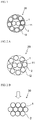
- FIG. 1 is a cross-sectional view illustrating a tire steel cord according to one preferred embodiment of the present invention.
- a steel cord 20 of the present invention has a layer-twisted structure including: a core 11 composed of two core filaments 1; and a sheath 12 composed of eight sheath filaments 2 that are twisted together around the core 11.
- the two core filaments 1 constituting the core 11 are twisted together.
- the steel cord 20 of the present invention has superior cutting resistance as compared to a conventional steel cord in which three core filaments are twisted together. The reasons for this are described below.
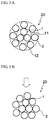
- FIG. 2A is a cross-sectional view illustrating a tire steel cord prior to a cut input according to one preferred embodiment of the present invention
- FIG. 2B is a cross-sectional view illustrating the tire steel cord when a cut input is made according to one preferred embodiment of the present invention
- FIG. 3A is a cross-sectional view of a steel cord having a 1 ⁇ 3+8 structure prior to a cut input
- FIG. 3B is a cross-sectional view of a steel cord having a 1 ⁇ 3+8 structure when a cut input is made.
- FIGS. 2B and 3A the positions of the core filaments 1 and the sheath filaments 2 are changed as illustrated in FIGS. 2B and 3B , respectively. It is noted here that the arrows in FIGS. 2B and 3B each represent the direction of the cut input.
- the core 11 is formed by twisting together two core filaments 1. Further, in order to allow the sheath filaments 2 to sink smoothly, it is preferred to use filaments having straightness as the core filaments 1 and the sheath filaments 2.
- the number of the sheath filaments 2 is 8.
- the shear load is reduced since the amount of steel per unit area of the steel cord is small.
- the number of the sheath filaments 2 is greater than 8, since the gaps between the sheath filaments 2 are small, the steel cord 20 cannot collapse into a flat shape, so that the shear load is reduced likewise.
- the small gaps between the sheath filaments 2 makes it difficult for a rubber to permeate thereinto, which is not preferred.
- the twisting direction of the core filaments 1 is different from the twisting direction of the sheath filaments 2. This makes it easy for a rubber to infiltrate into the steel cord 20, and the corrosion resistance of the steel cord 20 is thereby improved.
- deformation of a treat prepared by rubber-coating the steel cord 20 that is caused by cutting of the treat can be suppressed, so that not only excellent workability in the production of a tire using the steel cord 20 of the present invention but also an effect of inhibiting crack propagation against strains applied from various directions can be attained.
- the diameter (Dc) of the core filaments 1 and the diameter (Ds) of the sheath filaments 2 satisfy a relationship represented by the following Equation (1): 0.90 ⁇ Ds / Dc ⁇ 1.10
- the diameter (Dc) of the core filaments 1 and the diameter (Ds) of the sheath filaments 2 be both 0.30 to 0.55 mm.
- the diameter (Dc) of the core filaments 1 and the diameter (Ds) of the sheath filaments 2 are preferably 0.30 to 0.46 mm, more preferably 0.37 to 0.43 mm.
- the twisting pitch of the core filaments 1 be 5 to 15 mm. By controlling the twisting pitch of the core filaments 1 to be in this range, sufficient rubber permeability into the steel cord 20 can be attained.
- the twisting pitch of the core filaments 1 is more preferably 5 to 13 mm, still more preferably 7 to 9 mm.
- the twisting pitch of the sheath filaments 2 be preferably 9 to 30 mm.
- the twisting pitch of the sheath filaments 2 is preferably 9 mm or larger, the surface irregularities of the steel cord 20 can be reduced, as a result of which the adhesion between a rubber and the steel cord 20 is enhanced and the durability is thus improved.
- the twisting pitch of the sheath filaments 2 is preferably 30 mm or smaller, more preferably 9 to 26 mm, still more preferably 15 to 20 mm.
- the sum (S2) of the gap area (S1) of the sheath 12 and the cross-sectional areas of the sheath filaments 2 satisfy a relationship represented by the following Equation (2): 40 ⁇ S 1 / S 2 ⁇ 100 % ⁇ 120
- the "gap area (S1)" of the sheath 12 refers to the portion indicated with diagonal lines in FIG. 2 .
- S1/S2 ⁇ 100 (%) By controlling the value of S1/S2 ⁇ 100 (%) to be 40 or larger, the gap area of the sheath 12 can be sufficiently ensured, and the steel cord 20 is made more likely to deform into a flat shape when a cut is input.
- excellent rubber permeability is attained, so that a separation failure caused by corrosion of the steel cord 20 due to infiltration of water through a cut damage can be favorably inhibited.
- S1/S2 ⁇ 100 (%) by controlling the value of S1/S2 ⁇ 100 (%) to be 120 or smaller, a certain amount of steel in the sheath 12 is ensured, and sufficient cutting resistance as a reinforcing material can thus be ensured.
- the gap area (S1) of the sheath 12 be 0.30 mm 2 or larger.
- the effects of the present invention can be favorably obtained by adjusting the diameter (Dc) of the core filaments 1 and the diameter (Ds) of the sheath filaments 2 such that the gap area (S1) of the sheath 12 is 0.30 mm 2 or larger.
- the strength (F1) of the core filaments 1 and the strength (F2) of the sheath filaments 2 satisfy a relationship represented by the following Equation (3): F 1 / F 2 ⁇ 100 ⁇ 90 %
- the strength (F2) of the sheath filaments is preferably 150 N or greater and, taking into consideration the shear load, the upper limit of the F1 and F2 is 580 N or less.
- the steel cord 20 of the present invention includes the core 11 composed of the two core filaments 1 twisted together and the sheath 12 composed of the eight sheath filaments 2 twisted together in the opposite direction of the core filaments 1 and that the diameter (Dc) of the core filaments 1 and the diameter (Ds) of the sheath filaments 2 satisfy 0.90 ⁇ Ds/Dc ⁇ 1.10, and the steel cord 20 of the present invention is not particularly restricted with regard to other features of the constitution.
- the material of the steel filaments used in the steel cord 20 of the present invention is also not particularly restricted, and any conventionally used steel filaments can be used; however, the material is preferably a high-carbon steel containing not less than 0.80% by mass of a carbon component.
- the material is preferably a high-carbon steel containing not less than 0.80% by mass of a carbon component.
- a plating treatment may be performed on the surface of the steel cord 20 of the present invention.
- the composition of the plating to be applied to the surface of the steel cord 20 is not particularly restricted; however, a brass plating composed of copper and zinc is preferred, and a brass plating having a copper content of not less than 60% by mass is more preferred.
- the plating treatment the adhesion between the steel filaments and a rubber can be improved.
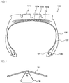
- FIG. 4 is a widthwise cross-sectional view illustrating a pneumatic tire according to one embodiment of the present invention.
- a tire 100 of the present invention includes: bead cores 101 arranged in a pair of left and right bead portions 106; and a tread portion 104 that is reinforced by a radial carcass 102, which extends from a crown portion to both bead portions 106 through side wall portions 105 and is wound around the bead cores 101 and thereby anchored to the respective bead portions 106, and a belt which is arranged on the crown portion tire radial-direction outer side of the radial carcass 102 and constituted by at least three belt layers 103a, 103b and 103c.
- the steel cord of the present invention has excellent cutting resistance and is, therefore, suitable as a reinforcing material of a heavy-duty pneumatic tire of a dump truck or the like, particularly as a reinforcing material of the outermost belt layer 103c, the intersecting belt layers 103a and 103b, and a belt reinforcing layer (not illustrated) that is arranged on the tire radial-direction outer side of the outermost belt layer 103c; however, the use of the steel cord of the present invention is not restricted thereto.
- the details of the tire constitution, the materials of the respective members and the like are not particularly restricted, and the tire 100 of the present invention can be configured by appropriately selecting conventionally known structure, materials and the like.
- a tread pattern is formed as appropriate on the surface of the tread portion 104
- bead fillers (not illustrated) are arranged on the tire radial-direction outer side of the respective bead cores 101
- an inner liner is arranged as an innermost layer of the tire 100.
- air having normal or adjusted oxygen partial pressure, or an inert gas such as nitrogen can be used as a gas filled into the tire 100 of the present invention.
- Double-layer twisted steel cords having the respective structures shown in Tables 1 to 5 below were prepared.
- the gap area (S1) of the sheath and the sum (S2) of the cross-sectional areas of the sheath filaments, as well as the value of S1/S2 ⁇ 100, the strength (F1) of the core filaments, the strength (F2) of the sheath filaments and the value of F1/F2 ⁇ 100 are all shown in the same Tables.
- the thus obtained steel cords were each evaluated for the below-described items. The evaluation methods were as follows.
- the thus obtained steel cords were each maintained in a bent state at 165°, and a jig 30 illustrated in FIG. 5 was pressed against each steel cord to measure the breaking strength.
- the cutting resistance of each steel cord was calculated by dividing the thus measured breaking strength by the value of simple tensile strength that had been separately measured in accordance with a conventional method (shear strength/simple tensile strength).
- the results thereof were indicated as index values taking the value determined for the steel cord of Comparative Example 1 as 100. A larger value means a better result, and a value of 400 or larger was regarded as satisfactory.
- Tables 1 to 5 The thus obtained results are also shown in Tables 1 to 5.
- the steel cords shown in Tables 1 to 5 were each embedded in a rubber to prepare steel cord-reinforced rubber samples, and the rubber penetration was evaluated. After dissecting the thus obtained samples and taking the steel cords therefrom, one end of each steel cord was immersed in a 10% aqueous NaOH solution and left to stand for 24 hours, and the "detached rubber length" was subsequently measured. If the rubber permeated into the steel cord, detachment of the rubber would not occur. The inverse value of the "detached rubber length" was determined and indicated as an index taking the value determined for the steel cord of Comparative Example 1 as 100. A larger value means a better result, and a value of 500 or larger was regarded as satisfactory. The results thereof are also shown in Tables 1 to 5.
- the ratio of simple tensile strength/cord diameter was calculated by dividing the simple tensile strength of each steel cord measured in accordance with a conventional method by the diameter of the steel cord. A value of 1,800 N/mm or larger was regarded as satisfactory. The results thereof are also shown in Tables 1 to 5.
- Tires of the type illustrated in FIG. 4 in which each of the thus obtained steel cords was applied as an outermost belt layer were produced at a tire size of 11R22.5/14PR.
- the angle of the outermost belt layer was set at ⁇ 20°, and the end count was set at 25 cords/50 mm.
- the thus obtained tires were each mounted on a rim having a size of 8.25 inches and then subjected to a 500-hour drum running test at an air pressure of 700 kPa, a load of 26.7 kN and a speed of 60 km/h. After the completion of the drum running test, each tire was cut and disassembled, and the length of a crack generated in the outermost belt layer was measured and indicated as an index based on Comparative Example 1.
- a larger value means superior tread separation resistance, and a value of 50 or larger was regarded as satisfactory.
- the results thereof are also shown in Tables 1 to 5.
- the steel cord of the present invention has not only excellent cutting resistance and corrosion resistance but also excellent processability in plant.
Landscapes
- Engineering & Computer Science (AREA)
- Mechanical Engineering (AREA)
- Ropes Or Cables (AREA)
- Tires In General (AREA)
Abstract
Description
- The present invention relates to a tire steel cord, and a pneumatic tire including the same (hereinafter, also simply referred to as "steel cord" and "tire", respectively). More particularly, the present invention relates to: a tire steel cord having not only excellent cutting resistance and corrosion resistance but also excellent processability in plant; and a pneumatic tire including the same.
- General dump truck tires running on rough ground on occasions are forced to run on road surfaces on which broken rocks are scattered. Thus, steel cords are widely used as reinforcing materials. Under such circumstances, as a steel cord for truck/bus tires that has excellent belt-end separation resistance and improves the tire durability and retreadability, for example,
Patent Document 1 proposes a steel cord which includes a core composed of one to three steel filaments and six to nine steel filaments twisted together around the core and satisfies prescribed physical properties. - [Patent Document 1]
J PH02-306801A - In dump truck tires, a belt cut failure is likely to occur due to running on rough ground. Thus, in order to improve the resistance against inputs of external damages, namely the cutting resistance, the steel cords used in belt layers are required to have a large shear load. Further, it is conceivable that infiltration of water through a cut damage causes corrosion of the steel cords and this leads to a separation failure. Accordingly, it is necessary to prevent infiltration of water into the steel cords by allowing a rubber to sufficiently permeate into the steel cords. Moreover, when steel cords are used in intersecting belt layers, the steel cords are also required to have sufficient strength such that they can withstand an internal pressure and a load applied thereto. Therefore, a further improvement is desired in those steel cords used in such tires.
- In view of the above, an object of the present invention is to provide: a tire steel cord having not only excellent cutting resistance and corrosion resistance but also excellent processability in plant; and a pneumatic tire including the same.
- The present inventor intensively studied to solve the above-described problems and consequently obtained the following findings. That is, by twisting cores together in a steel cord having a 2+8 structure, the cross-sections of the steel cords are allowed to deform when a cut is input, and the cut input can thereby be mitigated. In conventional steel cords in which the rubber permeation amount (rubber penetration amount) is insufficient, since the forces applied to the outermost sheath adhering with a rubber are concentrated, a crack generated due to belt-end distortion tends to propagate easily. However, by adopting a 2+8 structure and twisting core filaments and sheath filaments, which have the same diameter, in different directions, a sufficient rubber penetration amount is ensured, so that the steel cords as a whole can bear such distortion. Moreover, since the core filaments and the sheath filaments, which have the same diameter, each have the same surface area, distortion can be made more uniform and, by twisting the core filaments and the sheath filaments in different directions, the crack propagation resistance can be improved against strains applied from various directions. Based on these findings, the present inventor further intensively studied to discover that the above-described problems can be solved by adopting the below-described constitution, thereby completing the present invention.
- That is, the tire steel cord of the present invention is a tire steel cord having a layer-twisted structure including: a core composed of two core filaments; and a sheath composed of eight sheath filaments that are twisted together around the core,
the tire steel cord being characterized in that: - the two core filaments constituting the core are twisted together,
- the twisting direction of the core filaments and that of the sheath filaments are different, and
- a diameter (Dc) of the core filaments and a diameter (Ds) of the sheath filaments satisfy a relationship represented by the following Equation (1):

- In the steel cord of the present invention, it is preferred that the Dc and the Ds be the same. In the steel cord of the present invention, it is also preferred that the Dc and the Ds be both 0.30 to 0.55 mm. Further, in the steel cord of the present invention, it is preferred that the twisting pitch of the core filaments be 5 to 15 mm. Still further, in the steel cord of the present invention, it is preferred that the twisting pitch of the sheath filaments be 9 to 30 mm. Yet still further, in the steel cord of the present invention, it is preferred that a gap area (S1) of the sheath and a sum (S2) of cross-sectional areas of the sheath filaments satisfy a relationship represented by the following Equation (2):

- Yet still further, in the steel cord of the present invention, it is preferred that the gap area (S1) of the sheath be 0.30 mm2 or larger. Yet still further, in the steel cord of the present invention, it is preferred that a strength (F1) of the core filaments and a strength (F2) of the sheath filaments satisfy a relationship represented by the following Equation (3):

- Yet still further, in the steel cord of the present invention, it is preferred that the strength (F2) of the sheath filaments be 150 N or higher.
- The pneumatic tire of the present invention is characterized by including the tire steel cord of the present invention.
- According to the present invention, a tire steel cord having not only excellent cutting resistance and corrosion resistance but also excellent processability in plant, and a pneumatic tire including the same can be provided.
-
-
FIG. 1 is a cross-sectional view illustrating a tire steel cord according to one preferred embodiment of the present invention. -
FIG. 2A is a cross-sectional view illustrating a tire steel cord prior to a cut input according to one preferred embodiment of the present invention. -
FIG. 2B is a cross-sectional view illustrating a tire steel cord when a cut input is made according to one preferred embodiment of the present invention. -
FIG. 3A is a cross-sectional view of a steel cord having a 1×3+8 structure prior to a cut input. -
FIG. 3B is a cross-sectional view of a steel cord having a 1×3+8 structure when a cut input is made. -
FIG. 4 is a widthwise cross-sectional view illustrating a pneumatic tire according to one embodiment of the present invention. -
FIG. 5 is a schematic view illustrating a method of measuring the shear breaking strength of a steel cord. - The tire steel cord and pneumatic tire according to the present invention will now be described in detail referring to the drawings.
FIG. 1 is a cross-sectional view illustrating a tire steel cord according to one preferred embodiment of the present invention. As illustrated, asteel cord 20 of the present invention has a layer-twisted structure including: acore 11 composed of twocore filaments 1; and asheath 12 composed of eightsheath filaments 2 that are twisted together around thecore 11. In thesteel cord 20 of the present invention, the twocore filaments 1 constituting thecore 11 are twisted together. By adopting this constitution, thesteel cord 20 of the present invention has superior cutting resistance as compared to a conventional steel cord in which three core filaments are twisted together. The reasons for this are described below. -
FIG. 2A is a cross-sectional view illustrating a tire steel cord prior to a cut input according to one preferred embodiment of the present invention, andFIG. 2B is a cross-sectional view illustrating the tire steel cord when a cut input is made according to one preferred embodiment of the present invention.FIG. 3A is a cross-sectional view of a steel cord having a 1×3+8 structure prior to a cut input, andFIG. 3B is a cross-sectional view of a steel cord having a 1×3+8 structure when a cut input is made. When a cut is input to thesteel cord 20, in thesteel cords 20 having the respective cross-sections illustrated inFIGS. 2A and3A , the positions of thecore filaments 1 and thesheath filaments 2 are changed as illustrated inFIGS. 2B and3B , respectively. It is noted here that the arrows inFIGS. 2B and3B each represent the direction of the cut input. - Comparing the
FIGS. 2B and3B , since thesteel cord 20 having the core 11 composed of twocore filaments 1 that are twisted together has large gaps in the core 11 as illustrated inFIG. 2B , thesheath filaments 2 sink into the gaps of the core 11 when a cut is input, so that the cross-section of thesteel cord 20 can be deformed into a flat shape. Accordingly, the cut input can be mitigated and a high shear load is thereby attained. On the other hand, in thesteel cord 20 having the core 11 in which threecore filaments 1 are twisted together as illustrated inFIG. 3B , since there is no gap which thesheath filaments 2 can sink into when a cut is input, the cross-section of thesteel cord 20 cannot be deformed into a flat shape even with the cut input. Accordingly, the cut input cannot be mitigated, and the shear load is relatively small. Similarly, in those cases of steel cords having one or four core filaments, the core has no gap for the sheath filaments to sink into. Therefore, in thesteel cord 20 of the present invention, thecore 11 is formed by twisting together twocore filaments 1. Further, in order to allow thesheath filaments 2 to sink smoothly, it is preferred to use filaments having straightness as thecore filaments 1 and thesheath filaments 2. - In the
steel cord 20 of the present invention, the number of thesheath filaments 2 is 8. When the number of thesheath filaments 2 is less than 8, the shear load is reduced since the amount of steel per unit area of the steel cord is small. Meanwhile, when the number of thesheath filaments 2 is greater than 8, since the gaps between thesheath filaments 2 are small, thesteel cord 20 cannot collapse into a flat shape, so that the shear load is reduced likewise. In addition, the small gaps between thesheath filaments 2 makes it difficult for a rubber to permeate thereinto, which is not preferred. - Further, in the
steel cord 20 of the present invention, the twisting direction of thecore filaments 1 is different from the twisting direction of thesheath filaments 2. This makes it easy for a rubber to infiltrate into thesteel cord 20, and the corrosion resistance of thesteel cord 20 is thereby improved. In addition, because of the difference in the twisting direction between thecore filaments 1 and thesheath filaments 2, deformation of a treat prepared by rubber-coating thesteel cord 20 that is caused by cutting of the treat can be suppressed, so that not only excellent workability in the production of a tire using thesteel cord 20 of the present invention but also an effect of inhibiting crack propagation against strains applied from various directions can be attained. - Still further, in the
steel cord 20 of the present invention, the diameter (Dc) of thecore filaments 1 and the diameter (Ds) of thesheath filaments 2 satisfy a relationship represented by the following Equation (1):
- With the value of Ds/Dc satisfying this range, good rubber permeability into the
steel cord 20 can be ensured, and sufficient cutting resistance and strength can be attained. In order to favorably attain this effect, the Ds and the Dc satisfy preferably:

- Yet still further, in the
steel cord 20 of the present invention, it is preferred that the diameter (Dc) of thecore filaments 1 and the diameter (Ds) of thesheath filaments 2 be both 0.30 to 0.55 mm. By controlling the diameter (Dc) of thecore filaments 1 and the diameter (Ds) of thesheath filaments 2 to be in this range, good rubber permeability into thesteel cord 20 can be ensured likewise, and sufficient cutting resistance and strength can be attained. In order to favorably attain this effect, the diameter (Dc) and the diameter (Ds) are preferably 0.30 to 0.46 mm, more preferably 0.37 to 0.43 mm. - Yet still further, in the
steel cord 20 of the present invention, it is preferred that the twisting pitch of thecore filaments 1 be 5 to 15 mm. By controlling the twisting pitch of thecore filaments 1 to be in this range, sufficient rubber permeability into thesteel cord 20 can be attained. The twisting pitch of thecore filaments 1 is more preferably 5 to 13 mm, still more preferably 7 to 9 mm. - Yet still further, in the
steel cord 20 of the present invention, it is preferred that the twisting pitch of thesheath filaments 2 be preferably 9 to 30 mm. By controlling the twisting pitch of thesheath filaments 2 to be 9 mm or larger, the surface irregularities of thesteel cord 20 can be reduced, as a result of which the adhesion between a rubber and thesteel cord 20 is enhanced and the durability is thus improved. Meanwhile, when the twisting pitch of thesheath filaments 2 is large, spread of water along thesheath filaments 2 is accelerated. In order to inhibit this phenomenon, the twisting pitch of thesheath filaments 2 is preferably 30 mm or smaller, more preferably 9 to 26 mm, still more preferably 15 to 20 mm. - In the
steel cord 20 of the present invention, it is preferred that the sum (S2) of the gap area (S1) of thesheath 12 and the cross-sectional areas of thesheath filaments 2 satisfy a relationship represented by the following Equation (2):
- The "gap area (S1)" of the
sheath 12 refers to the portion indicated with diagonal lines inFIG. 2 . By controlling the value of S1/S2 × 100 (%) to be 40 or larger, the gap area of thesheath 12 can be sufficiently ensured, and thesteel cord 20 is made more likely to deform into a flat shape when a cut is input. In addition, since the gaps in thesheath 12 are increased, excellent rubber permeability is attained, so that a separation failure caused by corrosion of thesteel cord 20 due to infiltration of water through a cut damage can be favorably inhibited. Meanwhile, by controlling the value of S1/S2 × 100 (%) to be 120 or smaller, a certain amount of steel in thesheath 12 is ensured, and sufficient cutting resistance as a reinforcing material can thus be ensured. - The gap area (S1) of the
sheath 12 can be determined by the following Equation (6):
- r1: Diameter of core filaments
- r2: Diameter of sheath filaments
- N: Number of sheath filaments
- In the
steel cord 20 of the present invention, it is preferred that the gap area (S1) of thesheath 12 be 0.30 mm2 or larger. The effects of the present invention can be favorably obtained by adjusting the diameter (Dc) of thecore filaments 1 and the diameter (Ds) of thesheath filaments 2 such that the gap area (S1) of thesheath 12 is 0.30 mm2 or larger. - In the
steel cord 20 of the present invention, it is preferred that the strength (F1) of thecore filaments 1 and the strength (F2) of thesheath filaments 2 satisfy a relationship represented by the following Equation (3):
- In pneumatic tires, a strength is also demanded for belt layers. When the strength is insufficient, the pneumatic tires cannot withstand an internal pressure and a load, and their burst durability is reduced. However, when thick steel filaments are used for improving the strength, the rubber permeability into the steel cord is deteriorated. Moreover, an increase in the strength of the steel filaments for the purpose of increasing the strength of the belt layers, the shear load is deteriorated. Therefore, in the
steel cord 20 of the present invention, by satisfying the Equation (3), preferably by controlling the F1 and the F2 to be the same (F1 = F2), such problems are avoided and the strength of thesteel cord 20 is improved. The strength (F2) of the sheath filaments is preferably 150 N or greater and, taking into consideration the shear load, the upper limit of the F1 and F2 is 580 N or less. - In the
steel cord 20 of the present invention, what is important are only the features that thesteel cord 20 includes the core 11 composed of the twocore filaments 1 twisted together and thesheath 12 composed of the eightsheath filaments 2 twisted together in the opposite direction of thecore filaments 1 and that the diameter (Dc) of thecore filaments 1 and the diameter (Ds) of thesheath filaments 2 satisfy 0.90 ≤ Ds/Dc ≤ 1.10, and thesteel cord 20 of the present invention is not particularly restricted with regard to other features of the constitution. - The material of the steel filaments used in the
steel cord 20 of the present invention is also not particularly restricted, and any conventionally used steel filaments can be used; however, the material is preferably a high-carbon steel containing not less than 0.80% by mass of a carbon component. By using a high-hardness high-carbon steel containing not less than 0.80% by mass of a carbon component as the material of the filaments, the effects of the present invention can be favorably attained. Meanwhile, a carbon component content of greater than 1.5% by mass is not preferred since the ductility is reduced and the fatigue resistance is thus deteriorated. - A plating treatment may be performed on the surface of the
steel cord 20 of the present invention. The composition of the plating to be applied to the surface of thesteel cord 20 is not particularly restricted; however, a brass plating composed of copper and zinc is preferred, and a brass plating having a copper content of not less than 60% by mass is more preferred. By the plating treatment, the adhesion between the steel filaments and a rubber can be improved. - Next, the pneumatic tire of the present invention will be described.
- The pneumatic tire of the present invention includes the steel cord of the present invention.
FIG. 4 is a widthwise cross-sectional view illustrating a pneumatic tire according to one embodiment of the present invention. In the illustrated example, atire 100 of the present invention includes:bead cores 101 arranged in a pair of left andright bead portions 106; and atread portion 104 that is reinforced by aradial carcass 102, which extends from a crown portion to bothbead portions 106 throughside wall portions 105 and is wound around thebead cores 101 and thereby anchored to therespective bead portions 106, and a belt which is arranged on the crown portion tire radial-direction outer side of theradial carcass 102 and constituted by at least threebelt layers outermost belt layer 103c, the intersectingbelt layers outermost belt layer 103c; however, the use of the steel cord of the present invention is not restricted thereto. - In the
tire 100 of the present invention, the details of the tire constitution, the materials of the respective members and the like are not particularly restricted, and thetire 100 of the present invention can be configured by appropriately selecting conventionally known structure, materials and the like. For example, a tread pattern is formed as appropriate on the surface of thetread portion 104, bead fillers (not illustrated) are arranged on the tire radial-direction outer side of therespective bead cores 101, and an inner liner is arranged as an innermost layer of thetire 100. Further, as a gas filled into thetire 100 of the present invention, air having normal or adjusted oxygen partial pressure, or an inert gas such as nitrogen, can be used. - The present invention will now be described in more detail by way of examples thereof.
- Double-layer twisted steel cords having the respective structures shown in Tables 1 to 5 below were prepared. The gap area (S1) of the sheath and the sum (S2) of the cross-sectional areas of the sheath filaments, as well as the value of S1/S2 × 100, the strength (F1) of the core filaments, the strength (F2) of the sheath filaments and the value of F1/F2 × 100 are all shown in the same Tables. The thus obtained steel cords were each evaluated for the below-described items. The evaluation methods were as follows.
- The thus obtained steel cords were each maintained in a bent state at 165°, and a
jig 30 illustrated inFIG. 5 was pressed against each steel cord to measure the breaking strength. The cutting resistance of each steel cord was calculated by dividing the thus measured breaking strength by the value of simple tensile strength that had been separately measured in accordance with a conventional method (shear strength/simple tensile strength). The results thereof were indicated as index values taking the value determined for the steel cord of Comparative Example 1 as 100. A larger value means a better result, and a value of 400 or larger was regarded as satisfactory. The thus obtained results are also shown in Tables 1 to 5. - The steel cords shown in Tables 1 to 5 were each embedded in a rubber to prepare steel cord-reinforced rubber samples, and the rubber penetration was evaluated. After dissecting the thus obtained samples and taking the steel cords therefrom, one end of each steel cord was immersed in a 10% aqueous NaOH solution and left to stand for 24 hours, and the "detached rubber length" was subsequently measured. If the rubber permeated into the steel cord, detachment of the rubber would not occur. The inverse value of the "detached rubber length" was determined and indicated as an index taking the value determined for the steel cord of Comparative Example 1 as 100. A larger value means a better result, and a value of 500 or larger was regarded as satisfactory. The results thereof are also shown in Tables 1 to 5.
- The ratio of simple tensile strength/cord diameter was calculated by dividing the simple tensile strength of each steel cord measured in accordance with a conventional method by the diameter of the steel cord. A value of 1,800 N/mm or larger was regarded as satisfactory. The results thereof are also shown in Tables 1 to 5.
- Tires of the type illustrated in
FIG. 4 in which each of the thus obtained steel cords was applied as an outermost belt layer were produced at a tire size of 11R22.5/14PR. The angle of the outermost belt layer was set at ±20°, and the end count was set at 25 cords/50 mm. The thus obtained tires were each mounted on a rim having a size of 8.25 inches and then subjected to a 500-hour drum running test at an air pressure of 700 kPa, a load of 26.7 kN and a speed of 60 km/h. After the completion of the drum running test, each tire was cut and disassembled, and the length of a crack generated in the outermost belt layer was measured and indicated as an index based on Comparative Example 1. A larger value means superior tread separation resistance, and a value of 50 or larger was regarded as satisfactory. The results thereof are also shown in Tables 1 to 5. - In the process of cutting a treat prepared using each steel cord, an evaluation of "×" was given when an end of the treat warped and largely curled up to such an extent that the workability was deteriorated, while an evaluation of "○" was given when the curling was small and did not affect the workability. The results thereof are also shown in Tables 1 to 5.
[Table 1] Comparative Example 1 Example 1 Example 2 Example 3 Example 4 Comparative Example 2 Core Number of filaments 2 2 2 2 2 4 Filament diameter Dc (mm) 0.4 0.4 0.4 0.3 0.55 0.4 Filament strength F1 (N) 346 346 346 240 568 346 Filament twisting direction - Z S Z Z Z Twisting pitch (mm) - 8 8 8 8 8 Sheath Number of filaments 8 8 8 8 8 8 Filament diameter Ds (mm) 0.4 0.4 0.4 0.3 0.55 0.4 Filament strength F2 (N) 346 346 346 240 568 346 Filament twisting direction S S Z S S S Twisting pitch (mm) 17 17 17 17 17 17 Core-sheath filament twisting direction - different different different different different Ds/Dc 1.0 1.0 1.0 1.0 1.0 1.0 S1 (mm2) 0.32 0.50 0.50 0.28 0.95 0.71 S2 (mm2) 1.01 1.01 1.01 0.57 1.90 1.01 S1/S2 × 100(%) 31.8 50.0 50.0 50.0 50.0 70.7 F1/F2 × 100(%) 100 100 100 100 100 100 Cutting resistance (index) 100 662 662 691 632 248 Rubber penetration (index) 100 1,600 1,600 1,333 1,600 80 Simple tensile strength/cord diameter (N/mm) 2,060 1,960 1,960 1,810 2,340 2,130 Tread separation resistance (index) 100 100 100 90 100 100 Processability in plant ○ ○ ○ ○ ○ ○ [Table 2] Comparative Example 3 Comparative Example 4 Comparative Example 5 Comparative Example 6 Comparative Example 7 Example 5 Core Number of filaments 3 2 2 2 2 2 Filament diameter Dc (mm) 0.4 0.4 0.4 0.4 0.4 0.44 Filament strength F1 (N) 346 346 346 346 346 401 Filament twisting direction Z Z Z Z S Z Twisting pitch (mm) 8 8 8 8 8 8 Sheath Number of filaments 8 7 9 8 8 8 Filament diameter Ds (mm) 0.4 0.4 0.4 0.4 0.4 0.4 Filament strength F2 (N) 346 346 346 346 346 346 Filament twisting direction S S S Z S S Twisting pitch (mm) 17 17 17 17 17 17 Core-sheath filament twisting direction different different different same same different Ds/Dc 1.0 1.0 1.0 1.0 1.0 0.91 S1 (mm2) 0.58 0.63 0.38 0.50 0.50 0.60 S2 (mm2) 1.01 0.88 1.13 1.01 1.01 1.01 S1/S2 × 100(%) 57.7 71.4 33.3 50.0 50.0 60.0 F1/F2 × 100(%) 100 100 100 100 100 116 Cutting resistance (index) 248 496 414 721 721 453 Rubber penetration (index) 80 800 80 800 800 1,600 Simple tensile strength/cord diameter (N/mm) 2,080 1,760 2,160 2,090 2,090 1,930 Tread separation resistance (index) 100 100 100 100 100 100 Processability in plant ○ ○ ○ × × ○ [Table 3] Example 6 Comparative Example 8 Comparative Example 9 Example 7 Example 8 Comparative Example 10 Core Number of filaments 2 2 2 2 2 2 Filament diameter Dc (mm) 0.4 0.47 0.4 0.4 0.37 0.4 Filament strength F1 (N) 346 439 346 346 315 346 Filament twisting direction Z Z Z Z Z Z Twisting pitch (mm) 8 8 8 8 8 8 Sheath Number of filaments 8 8 8 8 8 8 Filament diameter Ds (mm) 0.44 0.4 0.45 0.37 0.4 0.34 Filament strength F2 (N) 401 346 413 315 346 279 Filament twisting direction S S S S S S Twisting pitch (mm) 17 17 17 17 17 17 Core-sheath filament twisting direction different different different different different different Ds/Dc 1.10 0.85 1.13 0.93 1.08 0.85 S1 (mm2) 0.50 0.68 0.49 0.50 0.43 0.49 S2 (mm2) 1.22 1.01 1.27 0.86 1.01 0.73 S1/S2 × 100(%) 40.9 67.5 38.9 58.1 42.5 67.6 F1/F2 × 100(%) 86 127 84 110 91 124 Cutting resistance (index) 453 439 439 453 453 439 Rubber penetration (index) 1,000 1,600 100 1,600 1,000 1,600 Simple tensile strength/cord diameter (N/mm) 2,100 1,780 2,130 1,890 2,000 1,790 Tread separation resistance (index) 100 100 100 100 100 100 Processability in plant ○ ○ ○ ○ ○ ○ [Table 4] Comparative Example 11 Example 9 Example 10 Example 11 Example 12 Example 13 Core Number of filaments 2 2 2 2 2 2 Filament diameter Dc (mm) 0.34 0.4 0.4 0.4 0.4 0.4 Filament strength F1 (N) 279 346 346 346 346 346 Filament twisting direction Z Z Z Z Z Z Twisting pitch (mm) 8 5 15 4 16 5 Sheath Number of filaments 8 8 8 8 8 8 Filament diameter Ds (mm) 0.4 0.4 0.4 0.4 0.4 0.4 Filament strength F2 (N) 346 346 346 346 346 346 Filament twisting direction S S S S S S Twisting pitch (mm) 17 17 17 17 17 9 Core-sheath filament twisting direction different different different different different different Ds/Dc 1.18 1.0 1.0 1.0 1.0 1.0 S1 (mm2) 0.35 0.50 0.50 0.50 0.50 0.50 S2 (mm2) 1.01 1.01 1.01 1.01 1.01 1.01 S1/S2 × 100(%) 35.0 50.0 50.0 50.0 50.0 50.0 F1/F2 × 100(%) 81 100 100 100 100 100 Cutting resistance (index) 439 632 691 617 694 617 Rubber penetration (index) 100 1,600 1,333 1,600 1,000 1,600 Simple tensile strength/cord diameter (N/mm) 2,040 1,940 1,980 1,940 1,980 1,910 Tread separation resistance (index) 100 100 100 100 100 80 Processability in plant ○ ○ ○ ○ ○ ○ [Table 5] Example 14 Example 15 Example 16 Example 17 Core Number of filaments 2 2 2 2 Filament diameter Dc (mm) 0.4 0.4 0.4 0.4 Filament strength F1 (N) 346 346 346 320 Filament twisting direction Z Z Z Z Twisting pitch (mm) 5 5 5 8 Sheath Number of filaments 8 8 8 8 Filament diameter Ds (mm) 0.4 0.4 0.4 0.4 Filament strength F2 (N) 346 346 346 320 Filament twisting direction S S S S Twisting pitch (mm) 30 8 31 17 Core-sheath filament twisting direction different different different different Ds/Dc 1.0 1.0 1.0 1.0 S1 (mm2) 0.50 0.50 0.50 0.50 S2 (mm2) 1.01 1.01 1.01 1.01 S1/S2 × 100(%) 50.0 50.0 50.0 50.0 F1/F2 × 100(%) 100 100 100 100 Cutting resistance (index) 647 610 648 662 Rubber penetration (index) 1,333 1,600 1,000 1,600 Simple tensile strength/cord diameter (N/mm) 2,010 1,910 2,010 1,810 Tread separation resistance (index) 100 80 100 100 Processability in plant ○ ○ ○ ○ - From Tables 1 to 5, it is seen that the steel cord of the present invention has not only excellent cutting resistance and corrosion resistance but also excellent processability in plant.
-
- 1: core filament
- 2: sheath filament
- 11: core
- 12: sheath
- 20: steel cord
- 30: jig
- 100: pneumatic tire
- 101: bead core
- 102: radial carcass
- 103: belt layer
- 104: tread portion
- 105: side wall portion
- 106: bead portion
Claims (10)
- A tire steel cord having a layer-twisted structure comprising:a core composed of two core filaments; anda sheath composed of eight sheath filaments that are twisted together around the core,wherein the two core filaments constituting the core are twisted together, the twisting direction of the core filaments and that of the sheath filaments are different, anda diameter (Dc) of the core filaments and a diameter (Ds) of the sheath filaments satisfy a relationship represented by the following Equation (1):

- The tire steel cord according to claim 1, wherein the Dc and the Ds are the same.
- The tire steel cord according to claim 1 or 2, wherein the Dc and the Ds are both 0.30 to 0.55 mm.
- The tire steel cord according to any one of claims 1 to 3, wherein the twisting pitch of the core filaments is 5 to 15 mm.
- The tire steel cord according to any one of claims 1 to 4, wherein the twisting pitch of the sheath filaments is 9 to 30 mm.
- The tire steel cord according to any one of claims 1 to 5, wherein a gap area (S1) of the sheath and a sum (S2) of cross-sectional areas of the sheath filaments satisfy a relationship represented by the following Equation (2):

- The tire steel cord according to any one of claims 1 to 6, wherein the gap area (S1) of the sheath is 0.30 mm2 or larger.
- The tire steel cord according to any one of claims 1 to 7, wherein a strength (F1) of the core filaments and a strength (F2) of the sheath filaments satisfy a relationship represented by the following Equation (3):

- The tire steel cord according to any one of claims 1 to 8, wherein the strength (F2) of the sheath filaments is 150 N or higher.
- A pneumatic tire comprising the tire steel cord according to any one of claims 1 to 9.
Applications Claiming Priority (2)
| Application Number | Priority Date | Filing Date | Title |
|---|---|---|---|
| JP2016154983A JP6717701B2 (en) | 2016-08-05 | 2016-08-05 | Steel cord for tire and pneumatic tire using the same |
| PCT/JP2017/027336 WO2018025753A1 (en) | 2016-08-05 | 2017-07-27 | Tire steel cord and pneumatic tire using same |
Publications (3)
| Publication Number | Publication Date |
|---|---|
| EP3495163A4 EP3495163A4 (en) | 2019-06-12 |
| EP3495163A1 true EP3495163A1 (en) | 2019-06-12 |
| EP3495163B1 EP3495163B1 (en) | 2021-01-06 |
Family
ID=61073562
Family Applications (1)
| Application Number | Title | Priority Date | Filing Date |
|---|---|---|---|
| EP17836859.3A Active EP3495163B1 (en) | 2016-08-05 | 2017-07-27 | Tire steel cord and pneumatic tire using same |
Country Status (6)
| Country | Link |
|---|---|
| US (1) | US11518193B2 (en) |
| EP (1) | EP3495163B1 (en) |
| JP (1) | JP6717701B2 (en) |
| CN (1) | CN109562647A (en) |
| ES (1) | ES2854123T3 (en) |
| WO (1) | WO2018025753A1 (en) |
Families Citing this family (3)
| Publication number | Priority date | Publication date | Assignee | Title |
|---|---|---|---|---|
| KR102285067B1 (en) * | 2019-04-18 | 2021-08-03 | 금호타이어 주식회사 | Steel cord for radial tire |
| CN113293633A (en) * | 2021-06-28 | 2021-08-24 | 嘉兴东方钢帘线有限公司 | Compact steel cord with 2+ N structure and manufacturing method thereof |
| WO2026052828A1 (en) | 2024-09-09 | 2026-03-12 | Intervet International B.V. | Intermediate useful in the preparation of prostaglandin f2 compounds |
Family Cites Families (23)
| Publication number | Priority date | Publication date | Assignee | Title |
|---|---|---|---|---|
| BE654920A (en) * | 1964-10-28 | 1965-02-15 | ||
| JPS515558Y1 (en) * | 1970-08-10 | 1976-02-16 | ||
| JPH0324636Y2 (en) * | 1985-06-18 | 1991-05-29 | ||
| US4690191A (en) | 1984-12-21 | 1987-09-01 | Bridgestone Corporation | Radial tire with reinforcing steel cord |
| JPS63235587A (en) | 1986-11-25 | 1988-09-30 | 横浜ゴム株式会社 | Pneumatic tire for heavy load |
| JPH0723591B2 (en) * | 1988-12-07 | 1995-03-15 | 株式会社ブリヂストン | Steel cord and pneumatic radial tire for reinforcing rubber articles |
| US5213640A (en) * | 1988-12-07 | 1993-05-25 | Bridgestone Corporation | Rubber article-reinforcing 2+8 steel cords and pneumatic tires using such steel cords |
| AU620194B2 (en) * | 1989-02-06 | 1992-02-13 | N.V. Bekaert S.A. | Compact cord |
| JP3045732B2 (en) * | 1989-05-22 | 2000-05-29 | 株式会社ブリヂストン | Radial tire |
| JPH04193605A (en) * | 1990-11-28 | 1992-07-13 | Bridgestone Corp | Large-sized radial tire |
| EP0501720B1 (en) * | 1991-02-25 | 1996-05-29 | Bridgestone Corporation | Rubber article-reinforcing steel cords and pneumatic tires using such steel cords |
| JP3100708B2 (en) | 1991-02-25 | 2000-10-23 | 株式会社ブリヂストン | Steel cord for reinforcing rubber articles and pneumatic radial tire using the same for belt layer |
| DE69516238T2 (en) * | 1994-11-14 | 2000-09-28 | Bridgestone Corp., Tokio/Tokyo | Steel rope for the reinforcement of elastomeric products |
| JP3606972B2 (en) | 1995-11-17 | 2005-01-05 | 株式会社ブリヂストン | Steel cord for reinforcing tire and pneumatic tire using the same |
| JPH1181166A (en) * | 1997-09-09 | 1999-03-26 | Bridgestone Metalpha Kk | Steel code for reinforcing rubber article |
| ES2257779T3 (en) * | 1997-09-25 | 2006-08-01 | Bridgestone Corporation | STEEL ROPE, PROCEDURE FOR THE MANUFACTURE OF THE SAME AND PNEUMATIC. |
| JP4050827B2 (en) * | 1998-06-16 | 2008-02-20 | 株式会社ブリヂストン | Steel cord for rubber article reinforcement |
| JP2001187509A (en) * | 1999-12-28 | 2001-07-10 | Sumitomo Rubber Ind Ltd | Radial tires for heavy loads |
| JP2001234486A (en) | 2000-02-25 | 2001-08-31 | Tokyo Seiko Co Ltd | Steel cord and rubber composite |
| FR2870164B1 (en) | 2004-05-12 | 2006-07-14 | Michelin Soc Tech | PNEUMATIC AND COMPOSITE METAL / RUBBER FOR PNEUMATIC |
| JP2007297765A (en) * | 2006-04-05 | 2007-11-15 | Sumitomo Denko Steel Wire Kk | Bead cord and vehicle tire |
| FR2947574B1 (en) | 2009-07-03 | 2012-11-09 | Michelin Soc Tech | CABLE MULTITORONS WHOSE ELEMENTARY TORONES ARE CABLES WITH TWO LAYERS GOMMES IN SITU. |
| KR101523429B1 (en) * | 2013-09-06 | 2015-05-27 | 한국타이어 주식회사 | Steel cord for reinforcing a tire and radial tire using the same |
-
2016
- 2016-08-05 JP JP2016154983A patent/JP6717701B2/en active Active
-
2017
- 2017-07-27 ES ES17836859T patent/ES2854123T3/en active Active
- 2017-07-27 WO PCT/JP2017/027336 patent/WO2018025753A1/en not_active Ceased
- 2017-07-27 US US16/323,046 patent/US11518193B2/en active Active
- 2017-07-27 CN CN201780046707.8A patent/CN109562647A/en active Pending
- 2017-07-27 EP EP17836859.3A patent/EP3495163B1/en active Active
Also Published As
| Publication number | Publication date |
|---|---|
| JP2018021284A (en) | 2018-02-08 |
| CN109562647A (en) | 2019-04-02 |
| WO2018025753A1 (en) | 2018-02-08 |
| EP3495163B1 (en) | 2021-01-06 |
| EP3495163A4 (en) | 2019-06-12 |
| US11518193B2 (en) | 2022-12-06 |
| US20190202240A1 (en) | 2019-07-04 |
| JP6717701B2 (en) | 2020-07-01 |
| ES2854123T3 (en) | 2021-09-20 |
Similar Documents
| Publication | Publication Date | Title |
|---|---|---|
| EP3027805B1 (en) | High elongation steel cord and pneumatic tire comprising said cord | |
| CN104420378B (en) | Tire reinforcement steel cord and use its radial | |
| JP6560677B2 (en) | Steel cord for rubber article reinforcement | |
| EP3495163B1 (en) | Tire steel cord and pneumatic tire using same | |
| EP3543399A1 (en) | Steel cord for reinforcing rubber articles and rubber crawler and tire using same | |
| EP3495164B1 (en) | Pneumatic tire | |
| EP3252228A1 (en) | Rubber-article-reinforcing steel cord and tire | |
| JP5718070B2 (en) | Pneumatic tire | |
| JP5602609B2 (en) | Steel cord for reinforcing rubber articles and pneumatic tire using the same | |
| EP3495165B1 (en) | Pneumatic tire | |
| JP6171759B2 (en) | Pneumatic radial tire | |
| JP2018176923A (en) | Pneumatic radial tire | |
| JP2009114594A (en) | Steel cord for reinforcing rubber article and tire | |
| KR20220157003A (en) | Steel cord for tire belt ply reinforcement | |
| KR101904621B1 (en) | Cable Bead for Pneumatic Tire | |
| JP2009084727A (en) | Rubber-steel cord composite, method for producing the same, and pneumatic tire using the same | |
| JP2007031890A (en) | Steel cord and pneumatic radial tire | |
| JP5718087B2 (en) | Pneumatic tire | |
| JP2008162366A (en) | Radial tire | |
| WO2016129595A1 (en) | Rubber article reinforcing steel cord and pneumatic tire using same | |
| JPH08104102A (en) | Steel radial tires |
Legal Events
| Date | Code | Title | Description |
|---|---|---|---|
| STAA | Information on the status of an ep patent application or granted ep patent |
Free format text: STATUS: THE INTERNATIONAL PUBLICATION HAS BEEN MADE |
|
| PUAI | Public reference made under article 153(3) epc to a published international application that has entered the european phase |
Free format text: ORIGINAL CODE: 0009012 |
|
| STAA | Information on the status of an ep patent application or granted ep patent |
Free format text: STATUS: REQUEST FOR EXAMINATION WAS MADE |
|
| 17P | Request for examination filed |
Effective date: 20190221 |
|
| A4 | Supplementary search report drawn up and despatched |
Effective date: 20190423 |
|
| AK | Designated contracting states |
Kind code of ref document: A1 Designated state(s): AL AT BE BG CH CY CZ DE DK EE ES FI FR GB GR HR HU IE IS IT LI LT LU LV MC MK MT NL NO PL PT RO RS SE SI SK SM TR |
|
| AX | Request for extension of the european patent |
Extension state: BA ME |
|
| DAV | Request for validation of the european patent (deleted) | ||
| DAX | Request for extension of the european patent (deleted) | ||
| STAA | Information on the status of an ep patent application or granted ep patent |
Free format text: STATUS: EXAMINATION IS IN PROGRESS |
|
| 17Q | First examination report despatched |
Effective date: 20191119 |
|
| GRAP | Despatch of communication of intention to grant a patent |
Free format text: ORIGINAL CODE: EPIDOSNIGR1 |
|
| STAA | Information on the status of an ep patent application or granted ep patent |
Free format text: STATUS: GRANT OF PATENT IS INTENDED |
|
| INTG | Intention to grant announced |
Effective date: 20200717 |
|
| GRAS | Grant fee paid |
Free format text: ORIGINAL CODE: EPIDOSNIGR3 |
|
| GRAA | (expected) grant |
Free format text: ORIGINAL CODE: 0009210 |
|
| STAA | Information on the status of an ep patent application or granted ep patent |
Free format text: STATUS: THE PATENT HAS BEEN GRANTED |
|
| AK | Designated contracting states |
Kind code of ref document: B1 Designated state(s): AL AT BE BG CH CY CZ DE DK EE ES FI FR GB GR HR HU IE IS IT LI LT LU LV MC MK MT NL NO PL PT RO RS SE SI SK SM TR |
|
| REG | Reference to a national code |
Ref country code: GB Ref legal event code: FG4D |
|
| REG | Reference to a national code |
Ref country code: AT Ref legal event code: REF Ref document number: 1351956 Country of ref document: AT Kind code of ref document: T Effective date: 20210115 Ref country code: CH Ref legal event code: EP |
|
| REG | Reference to a national code |
Ref country code: DE Ref legal event code: R096 Ref document number: 602017031156 Country of ref document: DE |
|
| REG | Reference to a national code |
Ref country code: IE Ref legal event code: FG4D |
|
| REG | Reference to a national code |
Ref country code: NL Ref legal event code: MP Effective date: 20210106 |
|
| REG | Reference to a national code |
Ref country code: AT Ref legal event code: MK05 Ref document number: 1351956 Country of ref document: AT Kind code of ref document: T Effective date: 20210106 |
|
| REG | Reference to a national code |
Ref country code: LT Ref legal event code: MG9D |
|
| PG25 | Lapsed in a contracting state [announced via postgrant information from national office to epo] |
Ref country code: GR Free format text: LAPSE BECAUSE OF FAILURE TO SUBMIT A TRANSLATION OF THE DESCRIPTION OR TO PAY THE FEE WITHIN THE PRESCRIBED TIME-LIMIT Effective date: 20210407 Ref country code: FI Free format text: LAPSE BECAUSE OF FAILURE TO SUBMIT A TRANSLATION OF THE DESCRIPTION OR TO PAY THE FEE WITHIN THE PRESCRIBED TIME-LIMIT Effective date: 20210106 Ref country code: HR Free format text: LAPSE BECAUSE OF FAILURE TO SUBMIT A TRANSLATION OF THE DESCRIPTION OR TO PAY THE FEE WITHIN THE PRESCRIBED TIME-LIMIT Effective date: 20210106 Ref country code: NO Free format text: LAPSE BECAUSE OF FAILURE TO SUBMIT A TRANSLATION OF THE DESCRIPTION OR TO PAY THE FEE WITHIN THE PRESCRIBED TIME-LIMIT Effective date: 20210406 Ref country code: PT Free format text: LAPSE BECAUSE OF FAILURE TO SUBMIT A TRANSLATION OF THE DESCRIPTION OR TO PAY THE FEE WITHIN THE PRESCRIBED TIME-LIMIT Effective date: 20210506 Ref country code: LT Free format text: LAPSE BECAUSE OF FAILURE TO SUBMIT A TRANSLATION OF THE DESCRIPTION OR TO PAY THE FEE WITHIN THE PRESCRIBED TIME-LIMIT Effective date: 20210106 Ref country code: BG Free format text: LAPSE BECAUSE OF FAILURE TO SUBMIT A TRANSLATION OF THE DESCRIPTION OR TO PAY THE FEE WITHIN THE PRESCRIBED TIME-LIMIT Effective date: 20210406 |
|
| PG25 | Lapsed in a contracting state [announced via postgrant information from national office to epo] |
Ref country code: RS Free format text: LAPSE BECAUSE OF FAILURE TO SUBMIT A TRANSLATION OF THE DESCRIPTION OR TO PAY THE FEE WITHIN THE PRESCRIBED TIME-LIMIT Effective date: 20210106 Ref country code: LV Free format text: LAPSE BECAUSE OF FAILURE TO SUBMIT A TRANSLATION OF THE DESCRIPTION OR TO PAY THE FEE WITHIN THE PRESCRIBED TIME-LIMIT Effective date: 20210106 Ref country code: PL Free format text: LAPSE BECAUSE OF FAILURE TO SUBMIT A TRANSLATION OF THE DESCRIPTION OR TO PAY THE FEE WITHIN THE PRESCRIBED TIME-LIMIT Effective date: 20210106 Ref country code: AT Free format text: LAPSE BECAUSE OF FAILURE TO SUBMIT A TRANSLATION OF THE DESCRIPTION OR TO PAY THE FEE WITHIN THE PRESCRIBED TIME-LIMIT Effective date: 20210106 Ref country code: SE Free format text: LAPSE BECAUSE OF FAILURE TO SUBMIT A TRANSLATION OF THE DESCRIPTION OR TO PAY THE FEE WITHIN THE PRESCRIBED TIME-LIMIT Effective date: 20210106 |
|
| REG | Reference to a national code |
Ref country code: ES Ref legal event code: FG2A Ref document number: 2854123 Country of ref document: ES Kind code of ref document: T3 Effective date: 20210920 |
|
| PG25 | Lapsed in a contracting state [announced via postgrant information from national office to epo] |
Ref country code: IS Free format text: LAPSE BECAUSE OF FAILURE TO SUBMIT A TRANSLATION OF THE DESCRIPTION OR TO PAY THE FEE WITHIN THE PRESCRIBED TIME-LIMIT Effective date: 20210506 |
|
| REG | Reference to a national code |
Ref country code: DE Ref legal event code: R097 Ref document number: 602017031156 Country of ref document: DE |
|
| PG25 | Lapsed in a contracting state [announced via postgrant information from national office to epo] |
Ref country code: SM Free format text: LAPSE BECAUSE OF FAILURE TO SUBMIT A TRANSLATION OF THE DESCRIPTION OR TO PAY THE FEE WITHIN THE PRESCRIBED TIME-LIMIT Effective date: 20210106 Ref country code: CZ Free format text: LAPSE BECAUSE OF FAILURE TO SUBMIT A TRANSLATION OF THE DESCRIPTION OR TO PAY THE FEE WITHIN THE PRESCRIBED TIME-LIMIT Effective date: 20210106 Ref country code: EE Free format text: LAPSE BECAUSE OF FAILURE TO SUBMIT A TRANSLATION OF THE DESCRIPTION OR TO PAY THE FEE WITHIN THE PRESCRIBED TIME-LIMIT Effective date: 20210106 |
|
| PLBE | No opposition filed within time limit |
Free format text: ORIGINAL CODE: 0009261 |
|
| STAA | Information on the status of an ep patent application or granted ep patent |
Free format text: STATUS: NO OPPOSITION FILED WITHIN TIME LIMIT |
|
| PG25 | Lapsed in a contracting state [announced via postgrant information from national office to epo] |
Ref country code: RO Free format text: LAPSE BECAUSE OF FAILURE TO SUBMIT A TRANSLATION OF THE DESCRIPTION OR TO PAY THE FEE WITHIN THE PRESCRIBED TIME-LIMIT Effective date: 20210106 Ref country code: DK Free format text: LAPSE BECAUSE OF FAILURE TO SUBMIT A TRANSLATION OF THE DESCRIPTION OR TO PAY THE FEE WITHIN THE PRESCRIBED TIME-LIMIT Effective date: 20210106 Ref country code: SK Free format text: LAPSE BECAUSE OF FAILURE TO SUBMIT A TRANSLATION OF THE DESCRIPTION OR TO PAY THE FEE WITHIN THE PRESCRIBED TIME-LIMIT Effective date: 20210106 |
|
| 26N | No opposition filed |
Effective date: 20211007 |
|
| PG25 | Lapsed in a contracting state [announced via postgrant information from national office to epo] |
Ref country code: AL Free format text: LAPSE BECAUSE OF FAILURE TO SUBMIT A TRANSLATION OF THE DESCRIPTION OR TO PAY THE FEE WITHIN THE PRESCRIBED TIME-LIMIT Effective date: 20210106 |
|
| REG | Reference to a national code |
Ref country code: DE Ref legal event code: R119 Ref document number: 602017031156 Country of ref document: DE |
|
| PG25 | Lapsed in a contracting state [announced via postgrant information from national office to epo] |
Ref country code: SI Free format text: LAPSE BECAUSE OF FAILURE TO SUBMIT A TRANSLATION OF THE DESCRIPTION OR TO PAY THE FEE WITHIN THE PRESCRIBED TIME-LIMIT Effective date: 20210106 |
|
| REG | Reference to a national code |
Ref country code: CH Ref legal event code: PL |
|
| GBPC | Gb: european patent ceased through non-payment of renewal fee |
Effective date: 20210727 |
|
| PG25 | Lapsed in a contracting state [announced via postgrant information from national office to epo] |
Ref country code: MC Free format text: LAPSE BECAUSE OF FAILURE TO SUBMIT A TRANSLATION OF THE DESCRIPTION OR TO PAY THE FEE WITHIN THE PRESCRIBED TIME-LIMIT Effective date: 20210106 |
|
| REG | Reference to a national code |
Ref country code: BE Ref legal event code: MM Effective date: 20210731 |
|
| PG25 | Lapsed in a contracting state [announced via postgrant information from national office to epo] |
Ref country code: LI Free format text: LAPSE BECAUSE OF NON-PAYMENT OF DUE FEES Effective date: 20210731 Ref country code: IT Free format text: LAPSE BECAUSE OF FAILURE TO SUBMIT A TRANSLATION OF THE DESCRIPTION OR TO PAY THE FEE WITHIN THE PRESCRIBED TIME-LIMIT Effective date: 20210106 Ref country code: GB Free format text: LAPSE BECAUSE OF NON-PAYMENT OF DUE FEES Effective date: 20210727 Ref country code: DE Free format text: LAPSE BECAUSE OF NON-PAYMENT OF DUE FEES Effective date: 20220201 Ref country code: CH Free format text: LAPSE BECAUSE OF NON-PAYMENT OF DUE FEES Effective date: 20210731 |
|
| PG25 | Lapsed in a contracting state [announced via postgrant information from national office to epo] |
Ref country code: IS Free format text: LAPSE BECAUSE OF FAILURE TO SUBMIT A TRANSLATION OF THE DESCRIPTION OR TO PAY THE FEE WITHIN THE PRESCRIBED TIME-LIMIT Effective date: 20210506 Ref country code: LU Free format text: LAPSE BECAUSE OF NON-PAYMENT OF DUE FEES Effective date: 20210727 |
|
| PG25 | Lapsed in a contracting state [announced via postgrant information from national office to epo] |
Ref country code: IE Free format text: LAPSE BECAUSE OF NON-PAYMENT OF DUE FEES Effective date: 20210727 Ref country code: BE Free format text: LAPSE BECAUSE OF NON-PAYMENT OF DUE FEES Effective date: 20210731 |
|
| PG25 | Lapsed in a contracting state [announced via postgrant information from national office to epo] |
Ref country code: NL Free format text: LAPSE BECAUSE OF NON-PAYMENT OF DUE FEES Effective date: 20210206 Ref country code: CY Free format text: LAPSE BECAUSE OF FAILURE TO SUBMIT A TRANSLATION OF THE DESCRIPTION OR TO PAY THE FEE WITHIN THE PRESCRIBED TIME-LIMIT Effective date: 20210106 |
|
| P01 | Opt-out of the competence of the unified patent court (upc) registered |
Effective date: 20230531 |
|
| PG25 | Lapsed in a contracting state [announced via postgrant information from national office to epo] |
Ref country code: HU Free format text: LAPSE BECAUSE OF FAILURE TO SUBMIT A TRANSLATION OF THE DESCRIPTION OR TO PAY THE FEE WITHIN THE PRESCRIBED TIME-LIMIT; INVALID AB INITIO Effective date: 20170727 |
|
| PGFP | Annual fee paid to national office [announced via postgrant information from national office to epo] |
Ref country code: ES Payment date: 20230927 Year of fee payment: 7 |
|
| PG25 | Lapsed in a contracting state [announced via postgrant information from national office to epo] |
Ref country code: MK Free format text: LAPSE BECAUSE OF FAILURE TO SUBMIT A TRANSLATION OF THE DESCRIPTION OR TO PAY THE FEE WITHIN THE PRESCRIBED TIME-LIMIT Effective date: 20210106 |
|
| PG25 | Lapsed in a contracting state [announced via postgrant information from national office to epo] |
Ref country code: MT Free format text: LAPSE BECAUSE OF FAILURE TO SUBMIT A TRANSLATION OF THE DESCRIPTION OR TO PAY THE FEE WITHIN THE PRESCRIBED TIME-LIMIT Effective date: 20210106 |
|
| REG | Reference to a national code |
Ref country code: ES Ref legal event code: FD2A Effective date: 20250902 |
|
| PG25 | Lapsed in a contracting state [announced via postgrant information from national office to epo] |
Ref country code: ES Free format text: LAPSE BECAUSE OF NON-PAYMENT OF DUE FEES Effective date: 20240728 |
|
| PGFP | Annual fee paid to national office [announced via postgrant information from national office to epo] |
Ref country code: FR Payment date: 20250725 Year of fee payment: 9 |
|
| PG25 | Lapsed in a contracting state [announced via postgrant information from national office to epo] |
Ref country code: TR Free format text: LAPSE BECAUSE OF FAILURE TO SUBMIT A TRANSLATION OF THE DESCRIPTION OR TO PAY THE FEE WITHIN THE PRESCRIBED TIME-LIMIT Effective date: 20210106 |