EP3495115B1 - 3d-laserdrucker - Google Patents
3d-laserdrucker Download PDFInfo
- Publication number
- EP3495115B1 EP3495115B1 EP18210566.8A EP18210566A EP3495115B1 EP 3495115 B1 EP3495115 B1 EP 3495115B1 EP 18210566 A EP18210566 A EP 18210566A EP 3495115 B1 EP3495115 B1 EP 3495115B1
- Authority
- EP
- European Patent Office
- Prior art keywords
- laser
- hopper
- conduit
- powder material
- platform
- Prior art date
- Legal status (The legal status is an assumption and is not a legal conclusion. Google has not performed a legal analysis and makes no representation as to the accuracy of the status listed.)
- Active
Links
- 239000000463 material Substances 0.000 claims description 39
- 239000000843 powder Substances 0.000 claims description 36
- 238000007648 laser printing Methods 0.000 claims description 3
- 239000012254 powdered material Substances 0.000 claims 3
- 238000011144 upstream manufacturing Methods 0.000 claims 1
- 239000007789 gas Substances 0.000 description 18
- IJGRMHOSHXDMSA-UHFFFAOYSA-N Atomic nitrogen Chemical compound N#N IJGRMHOSHXDMSA-UHFFFAOYSA-N 0.000 description 4
- 238000004880 explosion Methods 0.000 description 3
- 238000012423 maintenance Methods 0.000 description 3
- 239000002184 metal Substances 0.000 description 3
- XKRFYHLGVUSROY-UHFFFAOYSA-N Argon Chemical compound [Ar] XKRFYHLGVUSROY-UHFFFAOYSA-N 0.000 description 2
- 230000000694 effects Effects 0.000 description 2
- 229910052757 nitrogen Inorganic materials 0.000 description 2
- 229910052786 argon Inorganic materials 0.000 description 1
- 239000006185 dispersion Substances 0.000 description 1
- 239000002360 explosive Substances 0.000 description 1
- 239000011261 inert gas Substances 0.000 description 1
- 230000002452 interceptive effect Effects 0.000 description 1
- 238000002844 melting Methods 0.000 description 1
- 230000008018 melting Effects 0.000 description 1
- 238000000034 method Methods 0.000 description 1
- 238000000926 separation method Methods 0.000 description 1
Images

Classifications
-
- B—PERFORMING OPERATIONS; TRANSPORTING
- B29—WORKING OF PLASTICS; WORKING OF SUBSTANCES IN A PLASTIC STATE IN GENERAL
- B29C—SHAPING OR JOINING OF PLASTICS; SHAPING OF MATERIAL IN A PLASTIC STATE, NOT OTHERWISE PROVIDED FOR; AFTER-TREATMENT OF THE SHAPED PRODUCTS, e.g. REPAIRING
- B29C64/00—Additive manufacturing, i.e. manufacturing of three-dimensional [3D] objects by additive deposition, additive agglomeration or additive layering, e.g. by 3D printing, stereolithography or selective laser sintering
- B29C64/10—Processes of additive manufacturing
- B29C64/141—Processes of additive manufacturing using only solid materials
- B29C64/153—Processes of additive manufacturing using only solid materials using layers of powder being selectively joined, e.g. by selective laser sintering or melting
-
- B—PERFORMING OPERATIONS; TRANSPORTING
- B22—CASTING; POWDER METALLURGY
- B22F—WORKING METALLIC POWDER; MANUFACTURE OF ARTICLES FROM METALLIC POWDER; MAKING METALLIC POWDER; APPARATUS OR DEVICES SPECIALLY ADAPTED FOR METALLIC POWDER
- B22F10/00—Additive manufacturing of workpieces or articles from metallic powder
- B22F10/70—Recycling
- B22F10/73—Recycling of powder
-
- B—PERFORMING OPERATIONS; TRANSPORTING
- B22—CASTING; POWDER METALLURGY
- B22F—WORKING METALLIC POWDER; MANUFACTURE OF ARTICLES FROM METALLIC POWDER; MAKING METALLIC POWDER; APPARATUS OR DEVICES SPECIALLY ADAPTED FOR METALLIC POWDER
- B22F12/00—Apparatus or devices specially adapted for additive manufacturing; Auxiliary means for additive manufacturing; Combinations of additive manufacturing apparatus or devices with other processing apparatus or devices
- B22F12/50—Means for feeding of material, e.g. heads
- B22F12/52—Hoppers
-
- B—PERFORMING OPERATIONS; TRANSPORTING
- B22—CASTING; POWDER METALLURGY
- B22F—WORKING METALLIC POWDER; MANUFACTURE OF ARTICLES FROM METALLIC POWDER; MAKING METALLIC POWDER; APPARATUS OR DEVICES SPECIALLY ADAPTED FOR METALLIC POWDER
- B22F12/00—Apparatus or devices specially adapted for additive manufacturing; Auxiliary means for additive manufacturing; Combinations of additive manufacturing apparatus or devices with other processing apparatus or devices
- B22F12/50—Means for feeding of material, e.g. heads
- B22F12/53—Nozzles
-
- B—PERFORMING OPERATIONS; TRANSPORTING
- B29—WORKING OF PLASTICS; WORKING OF SUBSTANCES IN A PLASTIC STATE IN GENERAL
- B29C—SHAPING OR JOINING OF PLASTICS; SHAPING OF MATERIAL IN A PLASTIC STATE, NOT OTHERWISE PROVIDED FOR; AFTER-TREATMENT OF THE SHAPED PRODUCTS, e.g. REPAIRING
- B29C64/00—Additive manufacturing, i.e. manufacturing of three-dimensional [3D] objects by additive deposition, additive agglomeration or additive layering, e.g. by 3D printing, stereolithography or selective laser sintering
- B29C64/30—Auxiliary operations or equipment
- B29C64/357—Recycling
-
- B—PERFORMING OPERATIONS; TRANSPORTING
- B33—ADDITIVE MANUFACTURING TECHNOLOGY
- B33Y—ADDITIVE MANUFACTURING, i.e. MANUFACTURING OF THREE-DIMENSIONAL [3-D] OBJECTS BY ADDITIVE DEPOSITION, ADDITIVE AGGLOMERATION OR ADDITIVE LAYERING, e.g. BY 3-D PRINTING, STEREOLITHOGRAPHY OR SELECTIVE LASER SINTERING
- B33Y30/00—Apparatus for additive manufacturing; Details thereof or accessories therefor
-
- B—PERFORMING OPERATIONS; TRANSPORTING
- B33—ADDITIVE MANUFACTURING TECHNOLOGY
- B33Y—ADDITIVE MANUFACTURING, i.e. MANUFACTURING OF THREE-DIMENSIONAL [3-D] OBJECTS BY ADDITIVE DEPOSITION, ADDITIVE AGGLOMERATION OR ADDITIVE LAYERING, e.g. BY 3-D PRINTING, STEREOLITHOGRAPHY OR SELECTIVE LASER SINTERING
- B33Y40/00—Auxiliary operations or equipment, e.g. for material handling
-
- B—PERFORMING OPERATIONS; TRANSPORTING
- B33—ADDITIVE MANUFACTURING TECHNOLOGY
- B33Y—ADDITIVE MANUFACTURING, i.e. MANUFACTURING OF THREE-DIMENSIONAL [3-D] OBJECTS BY ADDITIVE DEPOSITION, ADDITIVE AGGLOMERATION OR ADDITIVE LAYERING, e.g. BY 3-D PRINTING, STEREOLITHOGRAPHY OR SELECTIVE LASER SINTERING
- B33Y50/00—Data acquisition or data processing for additive manufacturing
- B33Y50/02—Data acquisition or data processing for additive manufacturing for controlling or regulating additive manufacturing processes
-
- B—PERFORMING OPERATIONS; TRANSPORTING
- B22—CASTING; POWDER METALLURGY
- B22F—WORKING METALLIC POWDER; MANUFACTURE OF ARTICLES FROM METALLIC POWDER; MAKING METALLIC POWDER; APPARATUS OR DEVICES SPECIALLY ADAPTED FOR METALLIC POWDER
- B22F10/00—Additive manufacturing of workpieces or articles from metallic powder
- B22F10/30—Process control
- B22F10/32—Process control of the atmosphere, e.g. composition or pressure in a building chamber
- B22F10/322—Process control of the atmosphere, e.g. composition or pressure in a building chamber of the gas flow, e.g. rate or direction
-
- Y—GENERAL TAGGING OF NEW TECHNOLOGICAL DEVELOPMENTS; GENERAL TAGGING OF CROSS-SECTIONAL TECHNOLOGIES SPANNING OVER SEVERAL SECTIONS OF THE IPC; TECHNICAL SUBJECTS COVERED BY FORMER USPC CROSS-REFERENCE ART COLLECTIONS [XRACs] AND DIGESTS
- Y02—TECHNOLOGIES OR APPLICATIONS FOR MITIGATION OR ADAPTATION AGAINST CLIMATE CHANGE
- Y02P—CLIMATE CHANGE MITIGATION TECHNOLOGIES IN THE PRODUCTION OR PROCESSING OF GOODS
- Y02P10/00—Technologies related to metal processing
- Y02P10/25—Process efficiency
Definitions
- the present invention relates to a laser 3D printer.
- the present invention relates to a laser 3D printer of the type comprising a compartment, a platform which is engaged in a sliding manner in the compartment, a feeding assembly to feed a powder material onto the platform, a laser printing head to sinter the powder material disposed on the platform and a collection chamber.
- An object is produced by means of a repetition of work cycles, during which the products are made layer-by-layer, melting and solidifying the powder material.
- the platform is gradually lowered to enable the feeding assembly to feed, each time, a new layer of powder material onto the platform at the end of each operating cycle of the laser printing head.
- the platform On processing completion, the platform is lifted at an upper open end of the compartment to enable the retrieval of the produced item.
- the non-sintered powder is dropped into a collection chamber and has to be removed at the end of the processing.
- the laser 3D printers of the type described above have the drawback of requiring the direct intervention of an operator and a switched off printer for the manual emptying of the collection chamber.
- the powder material is very thin and volatile; therefore such an operation requires particular procedures and care in order to avoid an excessive dispersion of the powder material and inhalation by the operator.
- recirculation systems to automatically take back the powder material from a collection chamber to a distribution chamber
- recirculation systems being mechanical and comprising for example screw conveyors.
- the drawback of known recirculation systems is that they are expensive and complex to produce, they generate friction between the transported powder material and the recirculation system itself and have air gaps in which the powder material may accumulate.
- the purpose of the present invention is to provide a laser 3D printer that allows to automatically empty the collection chamber, i.e. without the intervention of an operator.
- the purpose of the present invention is to make a laser 3D printer that overcomes the drawbacks described above and that is simple and cheap to produce.
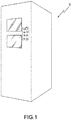
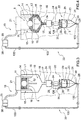
- the body 6 accommodates a tubular working compartment 8 inside it, which has a longitudinal axis 9 parallel to a direction 10 substantially vertical and perpendicular to the supporting plane ⁇ , extends downwards starting from the plane P and has a substantially square transversal section.
- the compartment 8 is delimited by a side wall 11 engaged in a sliding manner by a platform 12, which extends perpendicularly to the direction 10, and is movable along the compartment 8 in the direction 10 itself activated by a known actuating device which is not shown.
- the platform 12 is movable from a working position L1 (shown in Figure 3 ) to a discharge position L2 of the powder material 3 (shown in Figure 4 ) and vice versa.
- the platform 12 is connected with a known vibrating device, which is not shown, adapted to impart vibrations to the platform 12 itself according to a given law.
- the compartment 8 is located inside a collection chamber 13, which extends downwards starting from the plane P, further extends around the wall 11 and is delimited by a side wall 14.
- the walls 11, 14 define an annular channel 15 between them.
- the compartment 8 communicates with the chamber 13 through a lower opening 16.
- the wall 11 has one or more openings disposed in an intermediate part of the wall 11 and distributed around the axis 9.
- the chamber 13 comprises a bottom wall 18 that has an outlet 17 of the material 3.
- the wall 18 is configured to make the material 3 slide towards the outlet 17, in particular it slopes downwards.
- the printer 1 further comprises a feeding assembly 19 to feed the powder material 3 onto the platform 12.
- the feeding assembly 19 comprises a distribution tank 20 mounted above the body 7, and a dosing and distribution unit 21 mounted above the plane P and connected to the distribution tank 20.
- the printer 1 comprises a recirculation system 22 of the powder material 3 collected in the chamber 13 and fed to the outlet 17.
- the recirculation system 22 comprises a collection tank 23 disposed underneath the outlet 17; a conduit 24 extending between the outlet 17 and the tank 23.
- the recirculation system 22 further comprises a filter 25 mounted at the entrance of the conduit 24, in particular a sieve filter 25.
- the recirculation system 22 further comprises a valve 26 installed along the conduit 24 and interposed between the filter 25 and the tank 23.
- the valve 26 comprises an automatic actuator 126.
- the valve 26 is a pneumatically actuated ball valve.
- the tank 23 is a hopper which is fluidly connected to the valve 26 and disposed below the valve 26 to receive the powder material 3 that exits from the valve 26 itself.
- the hopper 23 has a longitudinal axis 28 substantially parallel to the direction 10 and perpendicular to the plane P.
- the hopper 23 has a cavity 29 and an outlet 30 of the material 3.
- the hopper 23 has a bottom wall 31 that delimits the cavity 29 inferiorly and delimits the outlet 30.
- the bottom wall 31 is configured to make the material 3 slide towards the outlet 30.
- the bottom wall 31 slopes downwards.
- the hopper 23 is made with a plurality of interconnected pieces, to be easily dismantled.
- the hopper 23 comprises a level sensor 32 configured to detect the filling level of the cavity 29.
- the hopper 23 has a maximum filling level.
- the recirculation system 22 further comprises a conduit 33 that connects the outlet 30 of the hopper 23 to the distribution tank 20.
- the conduit 33 is made with a plurality of interconnected portions 133. Thereby, the conduit 33 can be dismantled to allow maintenance activities inside each single portion 133.
- the recirculation system 22 comprises a gas ⁇ feeding system 34 configured to feed pressurised gas ⁇ into the cavity 29.
- the feeding system 34 comprises a source 35 of pressurised gas ⁇ , a nozzle 36 that is fixed to the hopper 23 and is configured to inject pressurised gas ⁇ into the cavity 29 in a position higher than the maximum level.
- the feeding system 34 comprises a tube 42, which connects the source 35 to the nozzle 36.
- the feeding system 34 comprises a regulation unit 37 interposed between the source 35 and the nozzle 36, to regulate the gas ⁇ flow fed to the nozzle 36.
- the regulation unit 37 comprises some solenoid valves configured to regulate, in a known manner, the pressure of the gas ⁇ fed by the hopper 23.
- the gas ⁇ is chosen amongst a group of different gases including for example air or inert gases such as nitrogen or argon.
- the gas ⁇ is nitrogen.
- the recirculation system 22 further comprises a gas filter 38 interposed between the conduit 33 and the distribution tank 20.
- the filter 38 is configured to allow the discharge of the gas ⁇ from the recirculation system 22, to allow only the feeding of the powder material 3 inside the distribution tank 20.
- the printer 1 further comprises a control unit 39, which is connected to the actuator 126 of the valve 26, to the level sensor 32 and to the regulation unit 37.
- the control unit 39 is also possibly connected to the source 35.
- control unit 39 comprises a memory unit 40, in which association data are stored for the association between processing parameters of the recirculation of the powder material 3 to be performed and operating parameters for performing the recirculation.
- control unit 39 further comprises a processing unit 41, which determines, in use, the operating parameters according to the detected processing parameters and the association data.
- the processing data comprise the filling level of the hopper 23 detected by the level sensor 32.
- the operating data comprise the pressure of the gas ⁇ discharged from the regulation unit 37 and the open/closed status of the valve 26.
- the control unit 39 further comprises a user interface 42 to exchange data externally, for example with an operator.
- the user interface 42 is a display, alternatively the user interface 42 is capable of exchanging data with a remote unit, for example a PC or a mobile device.
- a remote unit for example a PC or a mobile device.
- pneumatic transport can occur by thrusting or by suction.
- the recirculation system 22 is a thrusting and dense phase pneumatic transport system.
- the control unit 39 regulates the gas feeding system 34 to carry out a dense phase pneumatic transport of the powder material 3 along the conduit 33.
- the dosing and distribution unit 20 cyclically distributes the powder material 3 onto the platform 12.
- the platform 12 is always disposed in a working position (L1), which is above said lower opening 16 and that can vary between cycles.
- L1 working position
- the platform 12 is lowered underneath the lower opening 16, in a discharge position L2, and caused to vibrate to enable the material 3 to: exit from the compartment 8, enter into the chamber 13 and move towards the outlet 17.
- the non-sintered powder material 3 can fall also during processing on the side of the platform and through the lower opening. In this case the platform cannot be taken to a discharge position.
- the material 3 that goes through the outlet 17 is moved forward from the outlet 17 through the sieve filter 25, along the conduit 24, and into the tank 23, and is finally fed again into the distribution tank 20 by the recirculation system 22.
- the printer 1 has the advantage that the powder material 3 is partly used in order to make the object 2 and partly taken back by means of the recirculation system 22 into the tank 20, without being dispersed in the surroundings of the compartment 8 and without requiring retrieval operations of the residual material 3 by the responsible staff.
- the fact that the recirculation of the powder material 3 occurs with a pneumatic system allows to eliminate friction and wear compared to the known mechanical recirculation systems.
- the recirculation system 22 of the type described above is simpler and more economical to make, is more compact and is simpler and more economical to maintain.
- the valve 26 is closed to prevent the gas ⁇ and possibly some powder material 3 from going up into the compartment 8, through the outlet 17 and the chamber 13.
- valve 26 When the valve 26 is closed it allows to isolate the recirculation system 22 from the compartment 8. In other words, the recirculation system 22 is independent (stand alone). This entails a plurality of advantages:
- the transport of the powder material 3 occurs as dense phase pneumatic conveying allows to completely eliminate the risk of explosion, such as for example in the case of transport of metal powders.
- dense phase pneumatic conveying allows to use a conduit 33 with a small diameter. This allows to obtain a recirculation system of the powder material 3 which is safe and space-saving.
- the recirculation system 22 of the type described above can be dismantled easily and quickly, hence it is possible to carry out maintenance activities rapidly and simply also when the printer 1 is in operation, i.e. a processing in the compartment 8 is taking place.
Landscapes
- Engineering & Computer Science (AREA)
- Chemical & Material Sciences (AREA)
- Materials Engineering (AREA)
- Manufacturing & Machinery (AREA)
- Mechanical Engineering (AREA)
- Physics & Mathematics (AREA)
- Optics & Photonics (AREA)
- Life Sciences & Earth Sciences (AREA)
- Sustainable Development (AREA)
- Powder Metallurgy (AREA)
Claims (8)
- 3D-Laserdrucker, umfassend: ein Fach (8), das eine Längsachse (9) aufweist, die in Bezug auf eine Stütz- bzw. Trägerebene (π) im Wesentlichen vertikal ist, und das durch eine Seitenwand (11) begrenzt ist, die sich um die Längsachse (9) erstreckt; eine Plattform (12), die in dem Fach (8) auf gleitende Weise in Eingriff ist; eine Zuführanordnung (21) zum Zuführen eines Pulvermaterials (3) auf die Plattform (12); und einen Laserdruckkopf (4) zum Sintern des auf der Plattform (12) angeordneten Pulvermaterials (3); eine Kammer (13), die konfiguriert ist, in Gebrauch das nicht gesinterte Pulvermaterial (3) zu sammeln, das von der Plattform (12) fällt; wobei der Drucker (1) ein pneumatisches Rezirkulationssystem (22) umfasst, das konfiguriert ist, das pulverförmige Material (3) pneumatisch von der Kammer (13) zu der Zuführanordnung (21) zu transportieren; einen Trichter (23) und eine erste Leitung (24), welche die Kammer (13) mit dem Trichter (23) verbindet; wobei der Drucker dadurch gekennzeichnet ist, dass er ferner ein Ventil (26), das entlang der ersten Leitung (24) angeordnet und zwischen die Kammer (13) und den Trichter (23) geschaltet ist; eine zweite Leitung (33), die den Trichter (23) mit der Zuführanordnung (21) verbindet; eine Quelle (35) von Gas (ϕ), eine Düse (36) und ein Rohr (42) umfasst, das die Quelle (35) mit der Düse (36) verbindet; wobei der Trichter (23) einen Hohlraum (29) aufweist; die Düse (36) an dem Trichter (23) installiert ist, um das Gas (ϕ) in den Hohlraum (29) einzuspritzen und das pulverförmige Material (3) entlang der zweiten Leitung (33) zu drücken.
- 3D-Laserdrucker nach Anspruch 1 und umfassend einen Filter (38), der zwischen die zweite Leitung (33) und die Zuführanordnung (21) geschaltet ist; wobei der Filter (38) konfiguriert ist, das Gas nach außen auszustoßen und den Durchtritt zu der Zuführanordnung (21) hin nur dem pulverförmigen Material (3) zu erlauben.
- 3D-Laserdrucker nach einem der vorhergehenden Ansprüche und umfassend:
eine Regulierungseinheit (37), insbesondere ein Magnetventil, die entlang des Rohrs (42) stromaufwärts von der Düse (36) angeordnet ist; einen Aktor (126), der das Ventil (26) steuert bzw. regelt; einen Niveau- bzw. Füllstandsensor (32), der konfiguriert ist, Signale in Abhängigkeit von dem Füllstand des Hohlraums (29) zu erzeugen; und eine Steuer- bzw. Regeleinheit (39), die Daten austauscht mit: der Regulierungseinheit (37), dem Aktor (126) und dem Füllstandsensor (32). - 3D-Laserdrucker nach Anspruch 3, wobei die Steuer- bzw. Regeleinheit (39) umfasst: eine Speichereinheit (40), in der Assoziationsdaten für die Assoziation zwischen Verarbeitungsparametern der Rezirkulation des Pulvermaterials (3), die durchzuführen ist, und Betriebsparameter für die Rezirkulation gespeichert sind; und eine Verarbeitungseinheit (41), welche die Betriebsparameter in Abhängigkeit von den erfassten Verarbeitungsparametern und den Assoziationsdaten bestimmt; wobei die Verarbeitungsparameter den Füllstand des Hohlraums (29) umfassen; und die Betriebsparameter das Öffnen/Schließen des Ventils (26) und den der Düse (36) zugeführten Gasdruck (ϕ) umfassen, um den Transport als dichtphasiges pneumatisches Befördern des Pulvermaterials (3) zu erlauben.
- 3D-Laserdrucker nach einem der vorhergehenden Ansprüche, bei dem sich das Fach (8) innerhalb der Kammer (13) befindet, um einen ringförmigen Kanal (15) zu begrenzen; das Fach (8) mit der Kammer (13) durch eine untere Öffnung (16) kommuniziert; wobei die Plattform (12) von einer Arbeitsposition (L1) oberhalb der Öffnung (16) zu einer Ausstoßposition (L2) unterhalb der Öffnung (16) und umgekehrt bewegbar ist.
- 3D-Laserdrucker nach einem der vorhergehenden Ansprüche, wobei die zweite Leitung (33) eine Mehrzahl von Abschnitten (133) umfasst, die demontiert werden können.
- 3D-Laserdrucker nach den vorhergehenden Ansprüchen, in dem der Trichter (23) demontiert werden kann.
- 3D-Laserdrucker nach einem der vorhergehenden Ansprüche, bei dem das Ventil (26) ein Kugelhahn bzw. -ventil ist.
Applications Claiming Priority (1)
| Application Number | Priority Date | Filing Date | Title |
|---|---|---|---|
| IT201700141586 | 2017-12-07 |
Publications (2)
| Publication Number | Publication Date |
|---|---|
| EP3495115A1 EP3495115A1 (de) | 2019-06-12 |
| EP3495115B1 true EP3495115B1 (de) | 2020-08-05 |
Family
ID=61868621
Family Applications (1)
| Application Number | Title | Priority Date | Filing Date |
|---|---|---|---|
| EP18210566.8A Active EP3495115B1 (de) | 2017-12-07 | 2018-12-05 | 3d-laserdrucker |
Country Status (2)
| Country | Link |
|---|---|
| US (1) | US11135652B2 (de) |
| EP (1) | EP3495115B1 (de) |
Families Citing this family (4)
| Publication number | Priority date | Publication date | Assignee | Title |
|---|---|---|---|---|
| CN110860690A (zh) * | 2019-11-09 | 2020-03-06 | 上海航天设备制造总厂有限公司 | 一种用于金属增材制造设备的电气防爆系统及其选型方法 |
| DE102020120779A1 (de) * | 2020-08-06 | 2022-02-10 | Ossberger Gmbh + Co Kg | Trichterförmige Fördervorrichtung sowie ein Förder-Trenn-Verfahren für eine Bauteil-Partikelmaterial-Mischung |
| CN114905052B (zh) * | 2022-04-08 | 2024-03-19 | 江苏科技大学 | 一种激光3d打印多金属材料成型装置及其工作方法 |
| CN116117168B (zh) * | 2023-03-02 | 2025-01-21 | 南京铖联激光科技有限公司 | 一种金属铺粉3d打印机粉料自动处理系统 |
Family Cites Families (4)
| Publication number | Priority date | Publication date | Assignee | Title |
|---|---|---|---|---|
| CN103996394B (zh) | 2014-04-02 | 2017-06-16 | 黄锦坤 | 拨弦演奏数据产生装置 |
| TWI510279B (zh) * | 2014-04-22 | 2015-12-01 | 研能科技股份有限公司 | 粉末回收系統 |
| SE540662C2 (en) | 2015-02-19 | 2018-10-09 | Wematter Ab | System for manufacturing three-dimensional objects |
| JP6132962B1 (ja) * | 2016-06-01 | 2017-05-24 | 株式会社ソディック | 積層造形装置および積層造形装置の材料粉体の再利用方法 |
-
2018
- 2018-12-05 EP EP18210566.8A patent/EP3495115B1/de active Active
- 2018-12-05 US US16/210,616 patent/US11135652B2/en active Active
Non-Patent Citations (1)
| Title |
|---|
| None * |
Also Published As
| Publication number | Publication date |
|---|---|
| US11135652B2 (en) | 2021-10-05 |
| EP3495115A1 (de) | 2019-06-12 |
| US20190193157A1 (en) | 2019-06-27 |
Similar Documents
| Publication | Publication Date | Title |
|---|---|---|
| EP3495115B1 (de) | 3d-laserdrucker | |
| EP3473360B1 (de) | Pulverbettfusionsvorrichtung | |
| KR102340466B1 (ko) | 공압식 이송 장치 | |
| EP3431258B1 (de) | Vorrichtung zur generativen fertigung dreidimensionaler objekte | |
| US11396135B2 (en) | Powder reclamation and cleaning system for an additive manufacturing machine | |
| JP5073443B2 (ja) | 回転式粉末圧縮成型方法及びその装置 | |
| US20160129502A1 (en) | Powder dispenser for making a component by additive manufacturing | |
| KR20190002741U (ko) | 입자 블라스트 장치 | |
| EP2805782B1 (de) | Vorrichtung und verfahren zur kernherstellung | |
| US10179696B2 (en) | Variable opening slide gate for regulating material flow into airstream | |
| US9185933B2 (en) | Valve unit for filling angular transport channels with mass flow of rod like articles | |
| CN109573623A (zh) | 固体制剂的配料系统及其工作方式 | |
| CN109219559A (zh) | 用于吸烟制品有序群组的传送装置、包括上述传送装置的供给和形成吸烟制品有序群组的设备以及方法 | |
| US20220176454A1 (en) | Additive manufacturing powder recirculation system | |
| EP2799375B1 (de) | Pneumatisches Transportsystem, insbesondere für zerbrechliche Gegenstände | |
| JPH02191117A (ja) | タバコをパケツテイング機械のラツピングラインに供給する装置 | |
| KR20220100680A (ko) | 분말을 건조할 수 있는 적층 제조 분말 공급용 모듈 | |
| EP3509443B1 (de) | Zuführsystem, zuführeinheit, zuführvorrichtung und verfahren zum zuführen von stabförmigen elementen | |
| KR101808458B1 (ko) | 분체 공급장치 | |
| CN114746197B (zh) | 能够在惰性气氛下将粉末转移到容器中的增材制造粉末供应模块 | |
| EP2936084B1 (de) | Vorrichtung zum befördern eines betriebsstoffes | |
| JP2013001550A (ja) | 粉粒体の通過制御装置 | |
| EP2617524B1 (de) | Einspeisegeschwindigkeitssteuerung für granulierte Materialien | |
| JP2025031674A (ja) | ロッド状の物品を取り扱う装置及びこのような装置を初期充填する方法 | |
| KR102096755B1 (ko) | 파쇄노즐을 내부에 포함하여 수송 효율을 높일 수 있는 기송 장치 |
Legal Events
| Date | Code | Title | Description |
|---|---|---|---|
| PUAI | Public reference made under article 153(3) epc to a published international application that has entered the european phase |
Free format text: ORIGINAL CODE: 0009012 |
|
| STAA | Information on the status of an ep patent application or granted ep patent |
Free format text: STATUS: THE APPLICATION HAS BEEN PUBLISHED |
|
| AK | Designated contracting states |
Kind code of ref document: A1 Designated state(s): AL AT BE BG CH CY CZ DE DK EE ES FI FR GB GR HR HU IE IS IT LI LT LU LV MC MK MT NL NO PL PT RO RS SE SI SK SM TR |
|
| AX | Request for extension of the european patent |
Extension state: BA ME |
|
| STAA | Information on the status of an ep patent application or granted ep patent |
Free format text: STATUS: REQUEST FOR EXAMINATION WAS MADE |
|
| 17P | Request for examination filed |
Effective date: 20191211 |
|
| RBV | Designated contracting states (corrected) |
Designated state(s): AL AT BE BG CH CY CZ DE DK EE ES FI FR GB GR HR HU IE IS IT LI LT LU LV MC MK MT NL NO PL PT RO RS SE SI SK SM TR |
|
| GRAP | Despatch of communication of intention to grant a patent |
Free format text: ORIGINAL CODE: EPIDOSNIGR1 |
|
| STAA | Information on the status of an ep patent application or granted ep patent |
Free format text: STATUS: GRANT OF PATENT IS INTENDED |
|
| INTG | Intention to grant announced |
Effective date: 20200220 |
|
| GRAS | Grant fee paid |
Free format text: ORIGINAL CODE: EPIDOSNIGR3 |
|
| GRAA | (expected) grant |
Free format text: ORIGINAL CODE: 0009210 |
|
| STAA | Information on the status of an ep patent application or granted ep patent |
Free format text: STATUS: THE PATENT HAS BEEN GRANTED |
|
| AK | Designated contracting states |
Kind code of ref document: B1 Designated state(s): AL AT BE BG CH CY CZ DE DK EE ES FI FR GB GR HR HU IE IS IT LI LT LU LV MC MK MT NL NO PL PT RO RS SE SI SK SM TR |
|
| REG | Reference to a national code |
Ref country code: GB Ref legal event code: FG4D |
|
| REG | Reference to a national code |
Ref country code: CH Ref legal event code: EP |
|
| REG | Reference to a national code |
Ref country code: AT Ref legal event code: REF Ref document number: 1298115 Country of ref document: AT Kind code of ref document: T Effective date: 20200815 |
|
| REG | Reference to a national code |
Ref country code: DE Ref legal event code: R096 Ref document number: 602018006670 Country of ref document: DE |
|
| REG | Reference to a national code |
Ref country code: IE Ref legal event code: FG4D |
|
| REG | Reference to a national code |
Ref country code: CH Ref legal event code: NV Representative=s name: HEPP WENGER RYFFEL AG, CH |
|
| REG | Reference to a national code |
Ref country code: LT Ref legal event code: MG4D |
|
| REG | Reference to a national code |
Ref country code: NL Ref legal event code: MP Effective date: 20200805 |
|
| REG | Reference to a national code |
Ref country code: AT Ref legal event code: MK05 Ref document number: 1298115 Country of ref document: AT Kind code of ref document: T Effective date: 20200805 |
|
| PG25 | Lapsed in a contracting state [announced via postgrant information from national office to epo] |
Ref country code: FI Free format text: LAPSE BECAUSE OF FAILURE TO SUBMIT A TRANSLATION OF THE DESCRIPTION OR TO PAY THE FEE WITHIN THE PRESCRIBED TIME-LIMIT Effective date: 20200805 Ref country code: GR Free format text: LAPSE BECAUSE OF FAILURE TO SUBMIT A TRANSLATION OF THE DESCRIPTION OR TO PAY THE FEE WITHIN THE PRESCRIBED TIME-LIMIT Effective date: 20201106 Ref country code: SE Free format text: LAPSE BECAUSE OF FAILURE TO SUBMIT A TRANSLATION OF THE DESCRIPTION OR TO PAY THE FEE WITHIN THE PRESCRIBED TIME-LIMIT Effective date: 20200805 Ref country code: PT Free format text: LAPSE BECAUSE OF FAILURE TO SUBMIT A TRANSLATION OF THE DESCRIPTION OR TO PAY THE FEE WITHIN THE PRESCRIBED TIME-LIMIT Effective date: 20201207 Ref country code: NO Free format text: LAPSE BECAUSE OF FAILURE TO SUBMIT A TRANSLATION OF THE DESCRIPTION OR TO PAY THE FEE WITHIN THE PRESCRIBED TIME-LIMIT Effective date: 20201105 Ref country code: BG Free format text: LAPSE BECAUSE OF FAILURE TO SUBMIT A TRANSLATION OF THE DESCRIPTION OR TO PAY THE FEE WITHIN THE PRESCRIBED TIME-LIMIT Effective date: 20201105 Ref country code: ES Free format text: LAPSE BECAUSE OF FAILURE TO SUBMIT A TRANSLATION OF THE DESCRIPTION OR TO PAY THE FEE WITHIN THE PRESCRIBED TIME-LIMIT Effective date: 20200805 Ref country code: HR Free format text: LAPSE BECAUSE OF FAILURE TO SUBMIT A TRANSLATION OF THE DESCRIPTION OR TO PAY THE FEE WITHIN THE PRESCRIBED TIME-LIMIT Effective date: 20200805 Ref country code: AT Free format text: LAPSE BECAUSE OF FAILURE TO SUBMIT A TRANSLATION OF THE DESCRIPTION OR TO PAY THE FEE WITHIN THE PRESCRIBED TIME-LIMIT Effective date: 20200805 Ref country code: LT Free format text: LAPSE BECAUSE OF FAILURE TO SUBMIT A TRANSLATION OF THE DESCRIPTION OR TO PAY THE FEE WITHIN THE PRESCRIBED TIME-LIMIT Effective date: 20200805 |
|
| PG25 | Lapsed in a contracting state [announced via postgrant information from national office to epo] |
Ref country code: IS Free format text: LAPSE BECAUSE OF FAILURE TO SUBMIT A TRANSLATION OF THE DESCRIPTION OR TO PAY THE FEE WITHIN THE PRESCRIBED TIME-LIMIT Effective date: 20201205 Ref country code: LV Free format text: LAPSE BECAUSE OF FAILURE TO SUBMIT A TRANSLATION OF THE DESCRIPTION OR TO PAY THE FEE WITHIN THE PRESCRIBED TIME-LIMIT Effective date: 20200805 Ref country code: PL Free format text: LAPSE BECAUSE OF FAILURE TO SUBMIT A TRANSLATION OF THE DESCRIPTION OR TO PAY THE FEE WITHIN THE PRESCRIBED TIME-LIMIT Effective date: 20200805 Ref country code: NL Free format text: LAPSE BECAUSE OF FAILURE TO SUBMIT A TRANSLATION OF THE DESCRIPTION OR TO PAY THE FEE WITHIN THE PRESCRIBED TIME-LIMIT Effective date: 20200805 Ref country code: RS Free format text: LAPSE BECAUSE OF FAILURE TO SUBMIT A TRANSLATION OF THE DESCRIPTION OR TO PAY THE FEE WITHIN THE PRESCRIBED TIME-LIMIT Effective date: 20200805 |
|
| PG25 | Lapsed in a contracting state [announced via postgrant information from national office to epo] |
Ref country code: EE Free format text: LAPSE BECAUSE OF FAILURE TO SUBMIT A TRANSLATION OF THE DESCRIPTION OR TO PAY THE FEE WITHIN THE PRESCRIBED TIME-LIMIT Effective date: 20200805 Ref country code: RO Free format text: LAPSE BECAUSE OF FAILURE TO SUBMIT A TRANSLATION OF THE DESCRIPTION OR TO PAY THE FEE WITHIN THE PRESCRIBED TIME-LIMIT Effective date: 20200805 Ref country code: CZ Free format text: LAPSE BECAUSE OF FAILURE TO SUBMIT A TRANSLATION OF THE DESCRIPTION OR TO PAY THE FEE WITHIN THE PRESCRIBED TIME-LIMIT Effective date: 20200805 Ref country code: DK Free format text: LAPSE BECAUSE OF FAILURE TO SUBMIT A TRANSLATION OF THE DESCRIPTION OR TO PAY THE FEE WITHIN THE PRESCRIBED TIME-LIMIT Effective date: 20200805 Ref country code: SM Free format text: LAPSE BECAUSE OF FAILURE TO SUBMIT A TRANSLATION OF THE DESCRIPTION OR TO PAY THE FEE WITHIN THE PRESCRIBED TIME-LIMIT Effective date: 20200805 |
|
| REG | Reference to a national code |
Ref country code: DE Ref legal event code: R097 Ref document number: 602018006670 Country of ref document: DE |
|
| PG25 | Lapsed in a contracting state [announced via postgrant information from national office to epo] |
Ref country code: AL Free format text: LAPSE BECAUSE OF FAILURE TO SUBMIT A TRANSLATION OF THE DESCRIPTION OR TO PAY THE FEE WITHIN THE PRESCRIBED TIME-LIMIT Effective date: 20200805 |
|
| PLBE | No opposition filed within time limit |
Free format text: ORIGINAL CODE: 0009261 |
|
| STAA | Information on the status of an ep patent application or granted ep patent |
Free format text: STATUS: NO OPPOSITION FILED WITHIN TIME LIMIT |
|
| PG25 | Lapsed in a contracting state [announced via postgrant information from national office to epo] |
Ref country code: SK Free format text: LAPSE BECAUSE OF FAILURE TO SUBMIT A TRANSLATION OF THE DESCRIPTION OR TO PAY THE FEE WITHIN THE PRESCRIBED TIME-LIMIT Effective date: 20200805 |
|
| 26N | No opposition filed |
Effective date: 20210507 |
|
| PG25 | Lapsed in a contracting state [announced via postgrant information from national office to epo] |
Ref country code: MC Free format text: LAPSE BECAUSE OF FAILURE TO SUBMIT A TRANSLATION OF THE DESCRIPTION OR TO PAY THE FEE WITHIN THE PRESCRIBED TIME-LIMIT Effective date: 20200805 Ref country code: SI Free format text: LAPSE BECAUSE OF FAILURE TO SUBMIT A TRANSLATION OF THE DESCRIPTION OR TO PAY THE FEE WITHIN THE PRESCRIBED TIME-LIMIT Effective date: 20200805 |
|
| REG | Reference to a national code |
Ref country code: BE Ref legal event code: MM Effective date: 20201231 |
|
| PG25 | Lapsed in a contracting state [announced via postgrant information from national office to epo] |
Ref country code: IE Free format text: LAPSE BECAUSE OF NON-PAYMENT OF DUE FEES Effective date: 20201205 Ref country code: LU Free format text: LAPSE BECAUSE OF NON-PAYMENT OF DUE FEES Effective date: 20201205 |
|
| PG25 | Lapsed in a contracting state [announced via postgrant information from national office to epo] |
Ref country code: TR Free format text: LAPSE BECAUSE OF FAILURE TO SUBMIT A TRANSLATION OF THE DESCRIPTION OR TO PAY THE FEE WITHIN THE PRESCRIBED TIME-LIMIT Effective date: 20200805 Ref country code: MT Free format text: LAPSE BECAUSE OF FAILURE TO SUBMIT A TRANSLATION OF THE DESCRIPTION OR TO PAY THE FEE WITHIN THE PRESCRIBED TIME-LIMIT Effective date: 20200805 Ref country code: CY Free format text: LAPSE BECAUSE OF FAILURE TO SUBMIT A TRANSLATION OF THE DESCRIPTION OR TO PAY THE FEE WITHIN THE PRESCRIBED TIME-LIMIT Effective date: 20200805 |
|
| PG25 | Lapsed in a contracting state [announced via postgrant information from national office to epo] |
Ref country code: MK Free format text: LAPSE BECAUSE OF FAILURE TO SUBMIT A TRANSLATION OF THE DESCRIPTION OR TO PAY THE FEE WITHIN THE PRESCRIBED TIME-LIMIT Effective date: 20200805 |
|
| PG25 | Lapsed in a contracting state [announced via postgrant information from national office to epo] |
Ref country code: BE Free format text: LAPSE BECAUSE OF NON-PAYMENT OF DUE FEES Effective date: 20201231 |
|
| P01 | Opt-out of the competence of the unified patent court (upc) registered |
Effective date: 20230516 |
|
| PGFP | Annual fee paid to national office [announced via postgrant information from national office to epo] |
Ref country code: GB Payment date: 20241217 Year of fee payment: 7 |
|
| PGFP | Annual fee paid to national office [announced via postgrant information from national office to epo] |
Ref country code: FR Payment date: 20241227 Year of fee payment: 7 |
|
| PGFP | Annual fee paid to national office [announced via postgrant information from national office to epo] |
Ref country code: IT Payment date: 20241121 Year of fee payment: 7 |
|
| PGFP | Annual fee paid to national office [announced via postgrant information from national office to epo] |
Ref country code: DE Payment date: 20241227 Year of fee payment: 7 |
|
| PGFP | Annual fee paid to national office [announced via postgrant information from national office to epo] |
Ref country code: CH Payment date: 20250101 Year of fee payment: 7 |