EP3495046A1 - A shower - Google Patents
A shower Download PDFInfo
- Publication number
- EP3495046A1 EP3495046A1 EP18000685.0A EP18000685A EP3495046A1 EP 3495046 A1 EP3495046 A1 EP 3495046A1 EP 18000685 A EP18000685 A EP 18000685A EP 3495046 A1 EP3495046 A1 EP 3495046A1
- Authority
- EP
- European Patent Office
- Prior art keywords
- movable
- spout
- water outlet
- protruding
- outlet chamber
- Prior art date
- Legal status (The legal status is an assumption and is not a legal conclusion. Google has not performed a legal analysis and makes no representation as to the accuracy of the status listed.)
- Granted
Links
Images


Classifications
-
- B—PERFORMING OPERATIONS; TRANSPORTING
- B05—SPRAYING OR ATOMISING IN GENERAL; APPLYING FLUENT MATERIALS TO SURFACES, IN GENERAL
- B05B—SPRAYING APPARATUS; ATOMISING APPARATUS; NOZZLES
- B05B1/00—Nozzles, spray heads or other outlets, with or without auxiliary devices such as valves, heating means
- B05B1/14—Nozzles, spray heads or other outlets, with or without auxiliary devices such as valves, heating means with multiple outlet openings; with strainers in or outside the outlet opening
- B05B1/18—Roses; Shower heads
- B05B1/185—Roses; Shower heads characterised by their outlet element; Mounting arrangements therefor
-
- B—PERFORMING OPERATIONS; TRANSPORTING
- B05—SPRAYING OR ATOMISING IN GENERAL; APPLYING FLUENT MATERIALS TO SURFACES, IN GENERAL
- B05B—SPRAYING APPARATUS; ATOMISING APPARATUS; NOZZLES
- B05B1/00—Nozzles, spray heads or other outlets, with or without auxiliary devices such as valves, heating means
- B05B1/14—Nozzles, spray heads or other outlets, with or without auxiliary devices such as valves, heating means with multiple outlet openings; with strainers in or outside the outlet opening
- B05B1/18—Roses; Shower heads
-
- B—PERFORMING OPERATIONS; TRANSPORTING
- B05—SPRAYING OR ATOMISING IN GENERAL; APPLYING FLUENT MATERIALS TO SURFACES, IN GENERAL
- B05B—SPRAYING APPARATUS; ATOMISING APPARATUS; NOZZLES
- B05B15/00—Details of spraying plant or spraying apparatus not otherwise provided for; Accessories
- B05B15/50—Arrangements for cleaning; Arrangements for preventing deposits, drying-out or blockage; Arrangements for detecting improper discharge caused by the presence of foreign matter
- B05B15/52—Arrangements for cleaning; Arrangements for preventing deposits, drying-out or blockage; Arrangements for detecting improper discharge caused by the presence of foreign matter for removal of clogging particles
- B05B15/522—Arrangements for cleaning; Arrangements for preventing deposits, drying-out or blockage; Arrangements for detecting improper discharge caused by the presence of foreign matter for removal of clogging particles using cleaning elements penetrating the discharge openings
- B05B15/5223—Arrangements for cleaning; Arrangements for preventing deposits, drying-out or blockage; Arrangements for detecting improper discharge caused by the presence of foreign matter for removal of clogging particles using cleaning elements penetrating the discharge openings the cleaning element, e.g. a needle, and the discharge opening being movable relative to each other in a direction substantially parallel to the flow of liquid or other fluent material through said opening
- B05B15/5225—Arrangements for cleaning; Arrangements for preventing deposits, drying-out or blockage; Arrangements for detecting improper discharge caused by the presence of foreign matter for removal of clogging particles using cleaning elements penetrating the discharge openings the cleaning element, e.g. a needle, and the discharge opening being movable relative to each other in a direction substantially parallel to the flow of liquid or other fluent material through said opening the cleaning element being located upstream of the discharge opening or being actuated upstream therefrom
-
- E—FIXED CONSTRUCTIONS
- E03—WATER SUPPLY; SEWERAGE
- E03C—DOMESTIC PLUMBING INSTALLATIONS FOR FRESH WATER OR WASTE WATER; SINKS
- E03C1/00—Domestic plumbing installations for fresh water or waste water; Sinks
- E03C1/02—Plumbing installations for fresh water
- E03C1/04—Water-basin installations specially adapted to wash-basins or baths
- E03C1/0408—Water installations especially for showers
-
- B—PERFORMING OPERATIONS; TRANSPORTING
- B05—SPRAYING OR ATOMISING IN GENERAL; APPLYING FLUENT MATERIALS TO SURFACES, IN GENERAL
- B05B—SPRAYING APPARATUS; ATOMISING APPARATUS; NOZZLES
- B05B1/00—Nozzles, spray heads or other outlets, with or without auxiliary devices such as valves, heating means
- B05B1/02—Nozzles, spray heads or other outlets, with or without auxiliary devices such as valves, heating means designed to produce a jet, spray, or other discharge of particular shape or nature, e.g. in single drops, or having an outlet of particular shape
- B05B1/08—Nozzles, spray heads or other outlets, with or without auxiliary devices such as valves, heating means designed to produce a jet, spray, or other discharge of particular shape or nature, e.g. in single drops, or having an outlet of particular shape of pulsating nature, e.g. delivering liquid in successive separate quantities
- B05B1/083—Nozzles, spray heads or other outlets, with or without auxiliary devices such as valves, heating means designed to produce a jet, spray, or other discharge of particular shape or nature, e.g. in single drops, or having an outlet of particular shape of pulsating nature, e.g. delivering liquid in successive separate quantities the pulsating mechanism comprising movable parts
-
- B—PERFORMING OPERATIONS; TRANSPORTING
- B05—SPRAYING OR ATOMISING IN GENERAL; APPLYING FLUENT MATERIALS TO SURFACES, IN GENERAL
- B05B—SPRAYING APPARATUS; ATOMISING APPARATUS; NOZZLES
- B05B1/00—Nozzles, spray heads or other outlets, with or without auxiliary devices such as valves, heating means
- B05B1/02—Nozzles, spray heads or other outlets, with or without auxiliary devices such as valves, heating means designed to produce a jet, spray, or other discharge of particular shape or nature, e.g. in single drops, or having an outlet of particular shape
- B05B1/08—Nozzles, spray heads or other outlets, with or without auxiliary devices such as valves, heating means designed to produce a jet, spray, or other discharge of particular shape or nature, e.g. in single drops, or having an outlet of particular shape of pulsating nature, e.g. delivering liquid in successive separate quantities
- B05B1/083—Nozzles, spray heads or other outlets, with or without auxiliary devices such as valves, heating means designed to produce a jet, spray, or other discharge of particular shape or nature, e.g. in single drops, or having an outlet of particular shape of pulsating nature, e.g. delivering liquid in successive separate quantities the pulsating mechanism comprising movable parts
- B05B1/085—Nozzles, spray heads or other outlets, with or without auxiliary devices such as valves, heating means designed to produce a jet, spray, or other discharge of particular shape or nature, e.g. in single drops, or having an outlet of particular shape of pulsating nature, e.g. delivering liquid in successive separate quantities the pulsating mechanism comprising movable parts rotated by the liquid or other fluent material discharged, e.g. liquid rotated turbines
-
- B—PERFORMING OPERATIONS; TRANSPORTING
- B05—SPRAYING OR ATOMISING IN GENERAL; APPLYING FLUENT MATERIALS TO SURFACES, IN GENERAL
- B05B—SPRAYING APPARATUS; ATOMISING APPARATUS; NOZZLES
- B05B3/00—Spraying or sprinkling apparatus with moving outlet elements or moving deflecting elements
- B05B3/02—Spraying or sprinkling apparatus with moving outlet elements or moving deflecting elements with rotating elements
- B05B3/04—Spraying or sprinkling apparatus with moving outlet elements or moving deflecting elements with rotating elements driven by the liquid or other fluent material discharged, e.g. the liquid actuating a motor before passing to the outlet
Definitions
- the present invention relates to a sanitary product, and more particularly to a shower.
- a conventional shower includes a fixing portion provided with a water outlet chamber and a plurality of water diversion chambers, and a switching mechanism is disposed between the water diversion chambers and the water outlet chamber.
- the fixing portion has a cover portion.
- the cover portion has a plurality of water spouts which can be connected with the water outlet chamber, all the water spouts are divided into a plurality of regions, the plurality of regions and the plurality of water diversion chambers are corresponded to each other, and the different water outlet chambers generally discharge different functional water.
- the water chamber, a plurality of water diversion chamber and switching mechanism are all arranged, resulting in a complex internal structure ;
- the spout corresponding to different regions discharge different functional water, only the spout of the corresponding area discharge water, the spout of other area does not discharge water, the discharge water area is small..
- the present invention provides a shower that overcomes the deficiencies present in the shower of the background art.
- a shower comprising a fixed portion having a water outlet chamber, said fixed portion has a cover portion having a plurality of spouts for connecting to said water outlet chamber, comprising a movable portion, an operating member and a driving mechanism , the driving mechanism is in driving connection with the movable portion and drives the movable portion to circulate, the movable portion is movably arranged in the fixed portion and comprises a movable plate and a plurality of protruding portion protruding on the movable plate, the protruding portion is inserted into the spout and there is a gap between the protruding portion and the spout, the operating member is drivingly connected with the movable portion and the movable portion is driven by the operating member to move at least between the first position and the second position, and when the movable portion is in the first position or the second position, the spout discharges different functional water.
- the circulatory activity of the movable portion at least comprises rotational movement of the movable portion around an eccentric position, and the protruding portion rotates relative to a midline of the spout.
- the driving mechanism comprises a cam rotatable relative to the fixed portion, the movable plate is provided with a matching hole adapted to be sleeved on the cam, the operating member drives the movable portion to slide up and down along the cam between the first position and the second position.
- the protruding portion is narrowed in a tapered or conical manner toward to the outflow side.
- the spout has a peripheral wall protruding from the back surface of the cover portion, an upper port of the peripheral wall forms a first water inlet for connecting the water outlet chamber, the peripheral wall is provided with a second water inlet connecting to the water outlet chamber ; the protruding portion is inserted into the peripheral wall, and the movable plate at the first position covers the first water inlet.
- the upper port of the spout forms a first water inlet connecting to the water outlet chamber, and the spout is provided with a second water inlet which is oblique water hole capable of connecting to the water outlet chamber; the protruding portion is inserted into the peripheral wall, and the movable plate in the first position covers the first water inlet.
- the driving mechanism adopts a hydraulically driven driving mechanism.
- the fixing portion is provided with a water inlet passage for connecting the water outlet chamber, and the driving mechanism is connected between the water inlet passage and the water outlet chamber.
- the operating member comprises a button slidably connected to the fixed portion, and an automatic ballpoint pen mechanism is disposed between the button and the movable portion.
- the button is disposed at the center of the cover portion.
- the fixing portion further comprises a back cover portion, the back cover portion and the cover portion are relatively tightly fixed to each other, and the back cover portion and the cover portion form the above-mentioned water outlet chamber.
- a shower comprising a fixed portion having a water outlet chamber, said fixed portion has a cover portion having a plurality of spouts for connecting to said water outlet chamber, wherein comprising a movable portion and an operating member, the movable portion is movably disposed in the fixed portion and includes a movable plate and a plurality of protruding portion protruding from the movable plate, the protruding portion is inserted into the spout and there is a gap between the spout and the protruding portion, and the operating member and the movable portion are drivingly connected and the movable portion is driven by the operating member to move at least between the first position and the second position; the spout has a peripheral wall protruding from the back of the cover portion, an upper port of the peripheral wall forms a first water inlet for connecting water outlet chamber, a second water inlet which can be connected with the water outlet chamber is arranged on the
- a shower comprising a fixed portion having a water outlet chamber, the fixed portion has a cover portion having a plurality of water spouts capable of connecting to the water outlet chamber, wherein comprising a movable portion and an operating member, the movable portion is movably disposed in the fixed portion and includes a movable plate and a plurality of protruding portion protruding from the movable plate, the protruding portion is inserted into the spout and there is a gap between the spout and the protruding portion, and the operating member and the movable portion are drivingly connected and the movable portion is driven by the operating member to move at least between the first position and the second position; the upper port of the spout constitutes a first water inlet connected to the water outlet chamber, and the spout is provided with a second water inlet which is oblique water hole capable of connecting to the water outlet chamber; the protrud
- a shower comprising a fixed portion having a water outlet chamber
- the fixed portion has a cover portion having a plurality of spouts which are capable of being connected to a water outlet chamber
- the movable portion is movably disposed in the fixed portion and includes a movable plate and a plurality of protruding portion protruding from the movable plate
- the protruding portion is inserted into the spout and there is a gap between the spout and the protruding portion
- the driving mechanism is drivingly connected to the movable portion and drives the movable portion to circulate
- the circulatory activity of the movable portion at least comprises rotational movement of the movable portion around an eccentric position
- the protruding portion rotates relative to a midline of the spout.
- the utility model also comprises an movable portion, an operating member and a driving mechanism.
- the driving mechanism is in driving connection with the movable portion and drives the movable portion to circulate.
- the movable portion is arranged in the fixed portion and comprises a movable plate and a plurality of protruding portion protruding on the movable plate,
- the spout is inserted into the spout and there is a gap between the spout and the protruding portion
- the operating member is drivingly connected with the movable portion and the movable portion is driven by the operating member to move at least between the first position and the second position,when in the first position or the second, the movable portion discharge different functional water, when both in the first position and in the second position, the movable portion discharge water, the water area is large.
- the protruding portion of the movable portion moves regularly inside the spout to prevent fouling of the spout.
- the cyclic activity of the movable portion includes at least the rotational movement of the movable portion about the eccentric position, the protruding portion rotates relative to the middle of the spout, the protruding portion can agitate the water flow, and the discharge water massage effect is good so as to prevent the fouling and clogging of the spout.
- the protruding portion has a tapered structure with a large tail and a small tail , the discharge water massage is better.
- the operating element comprises a button which can be slidably connected with the fixed portion, an automatic ballpoint pen mechanism is arranged between the button and the movable portion, the structure is simple and compact.
- Button is located in the middle portion of the cover, it is easy to press.
- the peripheral wall is provided with a second water inlet which can be connected with the water outlet chamber, the protruding portion is inserted into the peripheral wall and the movable plate at the first position covers the first water inlet, or the spout is provided with a second water inlet which is oblique water hole connecting to the water outlet chamber, the protruding portion is inserted into the peripheral wall and the movable plate located at the first position covers the first water inlet, and the shower can generate granular water or shake the shower water.
- the cyclic activity of the movable portion includes at least the rotational movement of the movable portion about the eccentric position, and the protruding portion rotates relative to the middle of the spout.
- the protruding portion can agitate the flow of water. The effect of the discharge water massage is good and prevents fouling and clogging of the spout.
- the shower includes a fixed portion 10, a movable portion 20, an operating member 30 and a driving mechanism 40.
- the fixing portion 10 includes a cover portion 11 and a back cover portion 12.
- the cover portion 11 and the back cover portion 12 are relatively tightly fixedly connected with each other, and a water chamber 13 is formed between the cover portion 11 and the back cover portion 12.
- the cover portion 11 has a plurality of spout 111 capable of connecting with the water outlet chamber 13.
- the cover portion 11 includes a water outlet cover 112 and a decorative cover 113 stacked on the front surface of the water outlet cover 112.
- the stack-up fixture uses, for example, an adhesive structure or other fixed structure that is not removable or detachable; the water outlet cover 112 is provided with the spout 111, the decorative cover 113 is provided with a plurality of through holes penetrating up and down, and the water outlet cover 112 of the plurality of spout 111 is adapted to extend into the through hole and extend the front surface of the decorative cover 113.
- the back cover portion 12 includes a back cover 121 and a body 122 stacked on the back of the back cover 121.
- the back cover portion 12 is provided with a water inlet passage 128.
- the water surface cover 112 and the back cover 121 are fixedly connected by a screw, and a sealing ring is arranged between the water outlet cover 112 and the back cover 121.
- the main body 122 is convexly provided with a ring, the ring and the back cover 121 are fixedly connected by a buckle structure; the back cover portion 12 can be connected to the water supply source through the ball joint 123, the bushing 124 and the nut 125 and lead the water of the water supply source into the shower, and the water inlet passage 128 connects the water supply Source and the water outlet chambers 13; a water-stop 126 and a filter spacer 127 may also be provided in the ball joint 123 as required.
- the movable portion 20 is movably disposed in the water outlet chamber 13 of the fixing portion 10 and includes a movable plate 21 and a plurality of protruding portion 22 protruding from the front surface of the movable plate 21.
- the protruding portion 22 is narrowed in a tapered or conical manner toward the outflow side.
- the operating member 30 is movably disposed on the fixed portion 10, and the operating member 30 drivingly connects to the movable portion 20, and the operating member 30 drives the movable portion 20 to move between the first position and the second position.
- the driving mechanism 40 adopts a hydraulically driven driving mechanism 40 mounted between the water inlet passage 128 and the water outlet chamber 13.
- the driving mechanism 40 drivingly connects to the movable portion 20 and drives the movable portion 20 to move in cycle.
- the circulating movement includes at least the rotational movement of the movable portion 20 about the eccentric position, and the protruding portion 22 rotates relative to the midline of the spout 111, for example, the axis of spout 111.
- the movable portion 20 is drivingly connected to the driving mechanism 40 regardless of whether the movable plate 20 is in the first position or the second position, and the shower discharges different functional water when the movable portion 20 is in the first position and the second position.
- the operating member 30 includes a button 31 slidably connected to the fixing portion 10.
- An automatic ball-point pen mechanism is disposed between the button 31 and the movable portion 20.
- the button 31 is disposed at a middle position of the cover portion 11, for example.
- a concave groove 114 is recessed in the center of the front surface of the water outlet cover 112, and the decorative cover 113 is provided with a through hole and the through hole is aligned with the notch of the concave groove 114 to form a sliding groove.
- the button 31 is adapted to connected to the sliding groove to slide up and down relative to the cover portion 11.
- the automatic ballpoint pen mechanism comprises a first spring 32, a guide sliding shell 33, a ratchet shaft 34 and a second spring 35, and the guide sliding shell 33 is fixedly connected to the water outlet cover 112.
- the ratchet shaft 34 is arranged in the guide sliding shell 33.
- the first spring 32 abuts against between the ratchet shaft 34 and the button 31.
- the second spring 35 abuts against between the ratchet shaft 34 and the bottom of the groove 114.
- the back of the button 31, the guide sliding shell 33, the ratchet shaft 34 are provided with ratchet teeth and cooperate with each other so that they cooperate to form an automatic ballpoint pen mechanism;
- the ratchet shaft 34 is provided with an abutting column 36, which extends into water outlet chamber 13 from top to bottom and is drivingly connected with the movable plate 21, a sealing ring is arranged between the abutting column 36 and the water outlet cover 112, a abutting spring 23 is provided between the movable plate 20 and the back cover portion 12, the abutting spring 23, for example, against between the back of the movable plate and oblique water body 42.
- the driving connection may not need to use the abutting structure in the embodiment,other structures may be used directly.
- Pressing the button 31 causes the abutting column 36 to move upwards by an automatic ballpoint pen mechanism.
- the upward abutment of the abutting column 36 against the movable plate 20 moves the movable plate 20 upward from the first position to the second position, and the pushing spring 23 is in a compressed state; when the button 31 is pressed again, the button 31 is moved downward by the automatic ball-point pen mechanism to reset, the movable plate 20 moves downwards from the second position to the first position under the elastic force of the abutting spring 23.
- the driving mechanism 40 includes a cam 41 capable of rotating relative to the fixed portion 10.
- the movable plate 20 is provided with a mating hole 24.
- the mating hole 24 is adapted to be sleeved on the cam 41 ,and the rotation of the cam 41 drives the movable portion 20 to move about the eccentricity position.
- it can also use other structures to achieve the above trajectory, such as eccentric shaft mechanism.
- the first position and the second position of the movable portion 20 are spaced up and down along the rotation axis of the cam 41 and the cam can not only drive the movable portion to circulate but also guide the moving of the movable portion between the first position and the second position .
- the specific structure of the driving mechanism 40 is, for example, further includes a oblique water body 42 and an eccentric impeller 43.
- the oblique water body 42 includes a cup body 421 and a ring flange 422 extending outwardly from the upper periphery of the cup body 421.
- the cup wall of the cup body 421 is provided with a oblique water hole 423 .
- the ring flange 422 is fixedly connected with the back cover portion 12, and the oblique water body 42 is connected with the water inlet passage 128 and the water outlet chamber 13.
- the eccentric impeller 43 comprises an eccentric impeller portion 431 and a cam 41 fixed below the eccentric impeller 431.
- the eccentric impeller 43 is sleeved outside the cup body of the oblique water body 42; when the water inlet passage 128 enters the water, the water flows out of the oblique water hole to impact the eccentric impeller to rotate the eccentric impeller 43 , Which drives the rotation of the cam 41; wherein: a fixed shaft 424 is convexly arranged under the oblique water body, and the cam is adapted to rotate and be sleeved outside the fixed shaft.
- the spout 111 has a peripheral wall 115 protruding from the back of the water cover 112.
- An upper port of the peripheral wall 115 forms a first water inlet 116 for connecting the water outlet chamber 13, and the peripheral wall 115 is provided with a second water inlet 117 connecting to the water outlet chamber 13, the second water inlet is an oblique water hole; the protruding portion 22 is inserted into the peripheral wall 115, and the movable plate 21 located at the first position covers the first water inlet 116.
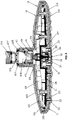
- the movable portion 20 is in the first position, the movable plate 21 covers the first water inlet 116, the water in the water outlet chamber 13 enters the water outlet spout 111 through the second water inlet 117, and the protruding portion 22 is inserted into the spout 111 and forms a ring-shaped chamber between the protruding portion 22 and the spout 111.
- the water flow in the annular chamber is swirled at a high speed to realize a vortex flow to generate a discrete effect, the shower water state is granular water. 2 As shown in FIG.
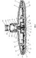
- pressing the button 31 lifts the movable portion 20 up to a second position.
- the movable plate 21 move away from the first water inlet 116, at this time, the first water inlet 116 of the end surface of the water spout 111 and the second water inlet 117 of the peripheral wall simultaneously feed water, and the influent water of the first water inlet interferes with the swirl of the water from the second inlet, so that the water flow out of the spout 111 form a columnar spray, under the action of the rotation of the protruding portion 22 around the axis of the spout 111, the shower water state is a shaking columnar spary.
- the movable portions are in different positions, and different water sprays can achieve different massage effects to suit different requirements of use. Moreover, different water sprays are discharged from the same spout, different functional water sprays have a same large outlet area.
- the movable portion is in different position, the water flow is unequal, it can achieve flow regulation.
- the setting of the movable portion avoids the problem of the residual water of the previous state when the function of the ordinary multi-function shower is switched, and the regular movement of the protruding portion 22 in the spout also removes the deposit of the spout.
- the invention may be summarized as follows:
- the invention disclosed a shower comprising a fixed portion having a water outlet chamber, the fixed portion having a cover portion having a plurality of spouts for connecting to the water outlet chamber, and a movable portion including an operating member and a driving mechanism .
- the driving mechanism is drivingly connected to the movable portion and drives the movable portion to circulate
- the movable portion is movably arranged in the fixed portion and comprises a movable plate and a plurality of protruding portion protruding on the movable plate, the protruding portion is inserted into the spout and there is a gap between the protruding portion and the spout
- the operating member is drivingly connected with the movable portion and is driven by the operating member to move at least between the first position and the second position
- the movable portion discharge different functional water when in the first position and the second position water.
- the utility model has the advantages that when the movable portion is in
Landscapes
- Health & Medical Sciences (AREA)
- Life Sciences & Earth Sciences (AREA)
- Engineering & Computer Science (AREA)
- Hydrology & Water Resources (AREA)
- Public Health (AREA)
- Water Supply & Treatment (AREA)
- Nozzles (AREA)
- Bathtubs, Showers, And Their Attachments (AREA)
Abstract
Description
- The present invention relates to a sanitary product, and more particularly to a shower.
- A conventional shower includes a fixing portion provided with a water outlet chamber and a plurality of water diversion chambers, and a switching mechanism is disposed between the water diversion chambers and the water outlet chamber. The fixing portion has a cover portion. The cover portion has a plurality of water spouts which can be connected with the water outlet chamber, all the water spouts are divided into a plurality of regions, the plurality of regions and the plurality of water diversion chambers are corresponded to each other, and the different water outlet chambers generally discharge different functional water. By switching the switching mechanism to make different water diversion chamber connect to the water outlet chamber, so that the spout of the area corresponding to the water diversion chamber discharge water , in order to achieve water switching function. It has the following deficiencies: First, the water chamber, a plurality of water diversion chamber and switching mechanism are all arranged, resulting in a complex internal structure ; Second, the spout corresponding to different regions discharge different functional water, only the spout of the corresponding area discharge water, the spout of other area does not discharge water, the discharge water area is small..
- The present invention provides a shower that overcomes the deficiencies present in the shower of the background art.
- The first technical solution adopted by the present invention for solving the technical problem is that:
A shower comprising a fixed portion having a water outlet chamber, said fixed portion has a cover portion having a plurality of spouts for connecting to said water outlet chamber, comprising a movable portion, an operating member and a driving mechanism , the driving mechanism is in driving connection with the movable portion and drives the movable portion to circulate, the movable portion is movably arranged in the fixed portion and comprises a movable plate and a plurality of protruding portion protruding on the movable plate, the protruding portion is inserted into the spout and there is a gap between the protruding portion and the spout, the operating member is drivingly connected with the movable portion and the movable portion is driven by the operating member to move at least between the first position and the second position, and when the movable portion is in the first position or the second position, the spout discharges different functional water. - In an embodiment, the circulatory activity of the movable portion at least comprises rotational movement of the movable portion around an eccentric position, and the protruding portion rotates relative to a midline of the spout.
- In an embodiment, the driving mechanism comprises a cam rotatable relative to the fixed portion, the movable plate is provided with a matching hole adapted to be sleeved on the cam, the operating member drives the movable portion to slide up and down along the cam between the first position and the second position.
- In an embodiment, the protruding portionis narrowed in a tapered or conical manner toward to the outflow side..
- In an embodiment, the spout has a peripheral wall protruding from the back surface of the cover portion, an upper port of the peripheral wall forms a first water inlet for connecting the water outlet chamber, the peripheral wall is provided with a second water inlet connecting to the water outlet chamber ; the protruding portion is inserted into the peripheral wall, and the movable plate at the first position covers the first water inlet.
- In an embodiment, the upper port of the spout forms a first water inlet connecting to the water outlet chamber, and the spout is provided with a second water inlet which is oblique water hole capable of connecting to the water outlet chamber; the protruding portion is inserted into the peripheral wall, and the movable plate in the first position covers the first water inlet.
- In an embodiment, the driving mechanism adopts a hydraulically driven driving mechanism.
- In an embodiment, the fixing portion is provided with a water inlet passage for connecting the water outlet chamber, and the driving mechanism is connected between the water inlet passage and the water outlet chamber.
- In an embodiment, the operating member comprises a button slidably connected to the fixed portion, and an automatic ballpoint pen mechanism is disposed between the button and the movable portion.
- In an embodiment, the button is disposed at the center of the cover portion.
- In an embodiment, the fixing portion further comprises a back cover portion, the back cover portion and the cover portion are relatively tightly fixed to each other, and the back cover portion and the cover portion form the above-mentioned water outlet chamber.
- The second technical solution adopted by the present invention for solving the technical problem is that:
A shower comprising a fixed portion having a water outlet chamber, said fixed portion has a cover portion having a plurality of spouts for connecting to said water outlet chamber, wherein comprising a movable portion and an operating member, the movable portion is movably disposed in the fixed portion and includes a movable plate and a plurality of protruding portion protruding from the movable plate, the protruding portion is inserted into the spout and there is a gap between the spout and the protruding portion, and the operating member and the movable portion are drivingly connected and the movable portion is driven by the operating member to move at least between the first position and the second position; the spout has a peripheral wall protruding from the back of the cover portion, an upper port of the peripheral wall forms a first water inlet for connecting water outlet chamber, a second water inlet which can be connected with the water outlet chamber is arranged on the peripheral wall, the protruding portion is inserted into the peripheral wall, and the movable plate in the first position covers the first water inlet. - The third technical solution adopted by the present invention for solving the technical problem is that:
A shower comprising a fixed portion having a water outlet chamber, the fixed portion has a cover portion having a plurality of water spouts capable of connecting to the water outlet chamber, wherein comprising a movable portion and an operating member, the movable portion is movably disposed in the fixed portion and includes a movable plate and a plurality of protruding portion protruding from the movable plate, the protruding portion is inserted into the spout and there is a gap between the spout and the protruding portion, and the operating member and the movable portion are drivingly connected and the movable portion is driven by the operating member to move at least between the first position and the second position; the upper port of the spout constitutes a first water inlet connected to the water outlet chamber, and the spout is provided with a second water inlet which is oblique water hole capable of connecting to the water outlet chamber; the protruding portion is inserted into the peripheral wall, and the movable plate located at the first position covers the first water Inlet. - The forth technical solution adopted by the present invention for solving the technical problem is that:
A shower, comprising a fixed portion having a water outlet chamber, the fixed portion has a cover portion having a plurality of spouts which are capable of being connected to a water outlet chamber, and wherein comprising a movable portion and a driving mechanism, the movable portion is movably disposed in the fixed portion and includes a movable plate and a plurality of protruding portion protruding from the movable plate,the protruding portion is inserted into the spout and there is a gap between the spout and the protruding portion,the driving mechanism is drivingly connected to the movable portion and drives the movable portion to circulate, the circulatory activity of the movable portion at least comprises rotational movement of the movable portion around an eccentric position, and the protruding portion rotates relative to a midline of the spout. - Compared with the background art, the technical solutions have the following advantages:
The utility model also comprises an movable portion, an operating member and a driving mechanism. The driving mechanism is in driving connection with the movable portion and drives the movable portion to circulate. The movable portion is arranged in the fixed portion and comprises a movable plate and a plurality of protruding portion protruding on the movable plate, The spout is inserted into the spout and there is a gap between the spout and the protruding portion, the operating member is drivingly connected with the movable portion and the movable portion is driven by the operating member to move at least between the first position and the second position,when in the first position or the second, the movable portion discharge different functional water, when both in the first position and in the second position, the movable portion discharge water, the water area is large. The protruding portion of the movable portion moves regularly inside the spout to prevent fouling of the spout. - The cyclic activity of the movable portion includes at least the rotational movement of the movable portion about the eccentric position, the protruding portion rotates relative to the middle of the spout, the protruding portion can agitate the water flow, and the discharge water massage effect is good so as to prevent the fouling and clogging of the spout.
- The protruding portion has a tapered structure with a large tail and a small tail , the discharge water massage is better.
- The operating element comprises a button which can be slidably connected with the fixed portion, an automatic ballpoint pen mechanism is arranged between the button and the movable portion, the structure is simple and compact.
- Button is located in the middle portion of the cover, it is easy to press.
- The peripheral wall is provided with a second water inlet which can be connected with the water outlet chamber, the protruding portion is inserted into the peripheral wall and the movable plate at the first position covers the first water inlet, or the spout is provided with a second water inlet which is oblique water hole connecting to the water outlet chamber, the protruding portion is inserted into the peripheral wall and the movable plate located at the first position covers the first water inlet, and the shower can generate granular water or shake the shower water.
- The cyclic activity of the movable portion includes at least the rotational movement of the movable portion about the eccentric position, and the protruding portion rotates relative to the middle of the spout. The protruding portion can agitate the flow of water. The effect of the discharge water massage is good and prevents fouling and clogging of the spout.
- The present invention will be further described below with reference to the accompanying drawings and embodiments.
-
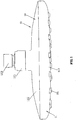
Figure 1 is a three-dimensional schematic view of the shower. -
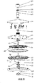
Figure 2 is a three-dimensional exploded view of the shower. -
Figure 3 is a cross-sectional view of the shower, when the movable portion is in the first position. -
Figure 4 is a cross-sectional view of the shower, when the movable portion in the second position. -
Figure 5 is the three-dimensional schematic view of the oblique water body. -
Figure 6 is the three-dimensional schematic view of the eccentric impeller. -
Figure 7 is the three-dimensional schematic view of the movable portion. -
Figure 8 is a three-dimensional schematic view of the water outlet cover. -
Figure 9 is an enlarged schematic view of A ofFigure 4 . - Please refer to
FIG. 1 to FIG. 9 , the shower includes a fixedportion 10, amovable portion 20, anoperating member 30 and adriving mechanism 40. - The
fixing portion 10 includes acover portion 11 and aback cover portion 12. Thecover portion 11 and theback cover portion 12 are relatively tightly fixedly connected with each other, and awater chamber 13 is formed between thecover portion 11 and theback cover portion 12. Thecover portion 11 has a plurality ofspout 111 capable of connecting with thewater outlet chamber 13. Thecover portion 11 includes awater outlet cover 112 and adecorative cover 113 stacked on the front surface of thewater outlet cover 112. The stack-up fixture uses, for example, an adhesive structure or other fixed structure that is not removable or detachable; thewater outlet cover 112 is provided with thespout 111, thedecorative cover 113 is provided with a plurality of through holes penetrating up and down, and thewater outlet cover 112 of the plurality ofspout 111 is adapted to extend into the through hole and extend the front surface of thedecorative cover 113. Theback cover portion 12 includes aback cover 121 and abody 122 stacked on the back of theback cover 121. Theback cover portion 12 is provided with awater inlet passage 128. In the present embodiment, thewater surface cover 112 and theback cover 121 are fixedly connected by a screw, and a sealing ring is arranged between thewater outlet cover 112 and theback cover 121. Themain body 122 is convexly provided with a ring, the ring and theback cover 121 are fixedly connected by a buckle structure; theback cover portion 12 can be connected to the water supply source through theball joint 123, thebushing 124 and thenut 125 and lead the water of the water supply source into the shower, and thewater inlet passage 128 connects the water supply Source and thewater outlet chambers 13; a water-stop 126 and afilter spacer 127 may also be provided in theball joint 123 as required. - The
movable portion 20 is movably disposed in thewater outlet chamber 13 of thefixing portion 10 and includes amovable plate 21 and a plurality of protrudingportion 22 protruding from the front surface of themovable plate 21. Theprotruding portion 22 is narrowed in a tapered or conical manner toward the outflow side. The operatingmember 30 is movably disposed on the fixedportion 10, and the operatingmember 30 drivingly connects to themovable portion 20, and the operatingmember 30 drives themovable portion 20 to move between the first position and the second position. Whether in the first position Position or the second position, the protrudingportion 22 are inserted into thespout 111 and there is a gap between thespout 111 and the protrudingportion 22 for the flow of water. Thedriving mechanism 40 adopts a hydraulically driven drivingmechanism 40 mounted between thewater inlet passage 128 and thewater outlet chamber 13. Thedriving mechanism 40 drivingly connects to themovable portion 20 and drives themovable portion 20 to move in cycle. The circulating movement includes at least the rotational movement of themovable portion 20 about the eccentric position, and the protrudingportion 22 rotates relative to the midline of thespout 111, for example, the axis ofspout 111. Themovable portion 20 is drivingly connected to thedriving mechanism 40 regardless of whether themovable plate 20 is in the first position or the second position, and the shower discharges different functional water when themovable portion 20 is in the first position and the second position. - The operating
member 30 includes abutton 31 slidably connected to the fixingportion 10. An automatic ball-point pen mechanism is disposed between thebutton 31 and themovable portion 20. Thebutton 31 is disposed at a middle position of thecover portion 11, for example. In the specific structure, aconcave groove 114 is recessed in the center of the front surface of thewater outlet cover 112, and thedecorative cover 113 is provided with a through hole and the through hole is aligned with the notch of theconcave groove 114 to form a sliding groove. Thebutton 31 is adapted to connected to the sliding groove to slide up and down relative to thecover portion 11. The automatic ballpoint pen mechanism comprises afirst spring 32, aguide sliding shell 33, aratchet shaft 34 and asecond spring 35, and theguide sliding shell 33 is fixedly connected to thewater outlet cover 112. Theratchet shaft 34 is arranged in theguide sliding shell 33. Thefirst spring 32 abuts against between theratchet shaft 34 and thebutton 31. Thesecond spring 35 abuts against between theratchet shaft 34 and the bottom of thegroove 114. The back of thebutton 31, theguide sliding shell 33, theratchet shaft 34 are provided with ratchet teeth and cooperate with each other so that they cooperate to form an automatic ballpoint pen mechanism; theratchet shaft 34 is provided with an abuttingcolumn 36, which extends intowater outlet chamber 13 from top to bottom and is drivingly connected with themovable plate 21, a sealing ring is arranged between the abuttingcolumn 36 and thewater outlet cover 112, a abuttingspring 23 is provided between themovable plate 20 and theback cover portion 12, the abuttingspring 23, for example, against between the back of the movable plate and oblique water body 42.The driving connection may not need to use the abutting structure in the embodiment,other structures may be used directly. Other structures may save the abutting spring . Pressing thebutton 31 causes the abuttingcolumn 36 to move upwards by an automatic ballpoint pen mechanism. The upward abutment of the abuttingcolumn 36 against themovable plate 20 moves themovable plate 20 upward from the first position to the second position, and the pushingspring 23 is in a compressed state; when thebutton 31 is pressed again, thebutton 31 is moved downward by the automatic ball-point pen mechanism to reset, themovable plate 20 moves downwards from the second position to the first position under the elastic force of the abuttingspring 23. - The
driving mechanism 40 includes acam 41 capable of rotating relative to the fixedportion 10. Themovable plate 20 is provided with amating hole 24. Themating hole 24 is adapted to be sleeved on thecam 41 ,and the rotation of thecam 41 drives themovable portion 20 to move about the eccentricity position. According to the need, it can also use other structures to achieve the above trajectory, such as eccentric shaft mechanism. Wherein the first position and the second position of themovable portion 20 are spaced up and down along the rotation axis of thecam 41 and the cam can not only drive the movable portion to circulate but also guide the moving of the movable portion between the first position and the second position . The specific structure of thedriving mechanism 40 is, for example, further includes aoblique water body 42 and aneccentric impeller 43. Theoblique water body 42 includes acup body 421 and aring flange 422 extending outwardly from the upper periphery of thecup body 421. The cup wall of thecup body 421 is provided with aoblique water hole 423 .Thering flange 422 is fixedly connected with theback cover portion 12, and theoblique water body 42 is connected with thewater inlet passage 128 and thewater outlet chamber 13. Theeccentric impeller 43 comprises aneccentric impeller portion 431 and acam 41 fixed below theeccentric impeller 431. Theeccentric impeller 43 is sleeved outside the cup body of theoblique water body 42; when thewater inlet passage 128 enters the water, the water flows out of the oblique water hole to impact the eccentric impeller to rotate theeccentric impeller 43 , Which drives the rotation of thecam 41; wherein: a fixedshaft 424 is convexly arranged under the oblique water body, and the cam is adapted to rotate and be sleeved outside the fixed shaft. - In this embodiment, the
spout 111 has aperipheral wall 115 protruding from the back of thewater cover 112. An upper port of theperipheral wall 115 forms afirst water inlet 116 for connecting thewater outlet chamber 13, and theperipheral wall 115 is provided with asecond water inlet 117 connecting to thewater outlet chamber 13, the second water inlet is an oblique water hole; the protrudingportion 22 is inserted into theperipheral wall 115, and themovable plate 21 located at the first position covers thefirst water inlet 116. wherein :1.as showed inFig.3 , themovable portion 20 is in the first position, themovable plate 21 covers thefirst water inlet 116, the water in thewater outlet chamber 13 enters thewater outlet spout 111 through thesecond water inlet 117, and the protrudingportion 22 is inserted into thespout 111 and forms a ring-shaped chamber between the protrudingportion 22 and thespout 111. Under the action of the rotation of the protrudingportion 22 around the axis of thespout 111, the water flow in the annular chamber is swirled at a high speed to realize a vortex flow to generate a discrete effect, the shower water state is granular water. 2, As shown inFIG. 4 , pressing thebutton 31 lifts themovable portion 20 up to a second position. Themovable plate 21 move away from thefirst water inlet 116, at this time, thefirst water inlet 116 of the end surface of thewater spout 111 and thesecond water inlet 117 of the peripheral wall simultaneously feed water, and the influent water of the first water inlet interferes with the swirl of the water from the second inlet, so that the water flow out of thespout 111 form a columnar spray, under the action of the rotation of the protrudingportion 22 around the axis of thespout 111, the shower water state is a shaking columnar spary. - In this embodiment, the movable portions are in different positions, and different water sprays can achieve different massage effects to suit different requirements of use. Moreover, different water sprays are discharged from the same spout, different functional water sprays have a same large outlet area. The movable portion is in different position, the water flow is unequal, it can achieve flow regulation. The setting of the movable portion avoids the problem of the residual water of the previous state when the function of the ordinary multi-function shower is switched, and the regular movement of the protruding
portion 22 in the spout also removes the deposit of the spout. - The invention may be summarized as follows: The invention disclosed a shower comprising a fixed portion having a water outlet chamber, the fixed portion having a cover portion having a plurality of spouts for connecting to the water outlet chamber, and a movable portion including an operating member and a driving mechanism .The driving mechanism is drivingly connected to the movable portion and drives the movable portion to circulate, the movable portion is movably arranged in the fixed portion and comprises a movable plate and a plurality of protruding portion protruding on the movable plate, the protruding portion is inserted into the spout and there is a gap between the protruding portion and the spout, the operating member is drivingly connected with the movable portion and is driven by the operating member to move at least between the first position and the second position, and the movable portion discharge different functional water when in the first position and the second position water. The utility model has the advantages that when the movable portion is in the first position or the second position, the spout discharge water and the water outlet area is large.
- The foregoing descriptions are merely exemplary embodiments of the present invention, and therefore, should not be taken as limitations on the scope of the present invention, ie, equivalent changes and modifications based on the scope of the patent and the contents of the specification should be covered by the present invention Range.
Claims (14)
- A shower comprising a fixed portion having a water outlet chamber, said fixed portion has a cover portion having a plurality of spouts for connecting to said water outlet chamber, wherein comprising a movable portion, an operating member and a driving mechanism , the driving mechanism is in driving connection with the movable portion and drives the movable portion to circulate, the movable portion is movably arranged in the fixed portion and comprises a movable plate and a plurality of protruding portion protruding on the movable plate, the protruding portion is inserted into the spout and there is a gap between the protruding portion and the spout, the operating member is drivingly connected with the movable portion and the movable portion is driven by the operating member to move at least between the first position and the second position, and when the movable portion is in the first position or the second position, the spout discharges different functional water.
- The shower according to claim 1, wherein the circulatory activity of the movable portion at least comprises rotational movement of the movable portion around an eccentric position, and the protruding portion rotates relative to a midline of the spout.
- The shower according to claim 1 and/or 2, wherein the driving mechanism comprises a cam rotatable relative to the fixed portion, the movable plate is provided with a matching hole adapted to be sleeved on the cam, the operating member drives the movable portion to slide up and down along the cam between the first position and the second position.
- The shower according to any one or more of claims 1 to 3, wherein the protruding portion is narrowed in a tapered or conical manner toward to the outflow side.
- The shower according to any one or more of claims 1 to 4, wherein the spout has a peripheral wall protruding from the back surface of the cover portion, an upper port of the peripheral wall forms a first water inlet for connecting the water outlet chamber, the peripheral wall is provided with a second water inlet connecting to the water outlet chamber; the protruding portion is inserted into the peripheral wall, and the movable plate at the first position covers the first water inlet.
- The shower according to any one or more of claims 1 to 5, wherein the upper port of the spout forms a first water inlet connecting to the water outlet chamber, and the spout is provided with a second water inlet which is oblique water hole capable of connecting to the water outlet chamber; the protruding portion is inserted into the peripheral wall, and the movable plate in the first position covers the first water inlet.
- The shower according to any one or more of claims 1 to 6, wherein the driving mechanism adopts a hydraulically driven driving mechanism.
- The shower according to any one or more of claims 1 to 7, wherein the fixing portion is provided with a water inlet passage for connecting the water outlet chamber, and the driving mechanism is connected between the water inlet passage and the water outlet chamber.
- The shower according to any one or more of claims 1 to 8, wherein the operating member comprises a button slidably connected to the fixed portion, and an automatic ballpoint pen mechanism is disposed between the button and the movable portion.
- The shower according to any one or more of claims 1 to 9, wherein the button is disposed at the center of the cover portion.
- The shower according to any one or more of claims 1 to 10, wherein the fixing portion further comprises a back cover portion, the back cover portion and the cover portion are relatively tightly fixed to each other, and the back cover portion and the cover portion form the above-mentioned water outlet chamber.
- A shower comprising a fixed portion having a water outlet chamber, said fixed portion has a cover portion having a plurality of spouts for connecting to said water outlet chamber, wherein comprising a movable portion and an operating member, the movable portion is movably disposed in the fixed portion and includes a movable plate and a plurality of protruding portion protruding from the movable plate, the protruding portion is inserted into the spout and there is a gap between the spout and the protruding portion, and the operating member and the movable portion are drivingly connected and the movable portion is driven by the operating member to move at least between the first position and the second position; the spout has a peripheral wall protruding from the back of the cover portion, an upper port of the peripheral wall forms a first water inlet for connecting water outlet chamber, a second water inlet which can be connected with the water outlet chamber is arranged on the peripheral wall, the protruding portion is inserted into the peripheral wall, and the movable plate in the first position covers the first water inlet.
- A shower comprising a fixed portion having a water outlet chamber, the fixed portion has a cover portion having a plurality of water spouts capable of connecting to the water outlet chamber, wherein comprising a movable portion and an operating member, the movable portion is movably disposed in the fixed portion and includes a movable plate and a plurality of protruding portion protruding from the movable plate, the protruding portion is inserted into the spout and there is a gap between the spout and the protruding portion, and the operating member and the movable portion are drivingly connected and the movable portion is driven by the operating member to move at least between the first position and the second position; the upper port of the spout constitutes a first water inlet connected to the water outlet chamber, and the spout is provided with a second water inlet which is oblique water hole capable of connecting to the water outlet chamber; the protruding portion is inserted into the peripheral wall, and the movable plate located at the first position covers the first water inlet.
- A shower, comprising a fixed portion having a water outlet chamber, the fixed portion has a cover portion having a plurality of spouts which are capable of being connected to a water outlet chamber, and wherein comprising a movable portion and a driving mechanism, the movable portion is movably disposed in the fixed portion and includes a movable plate and a plurality of protruding portion protruding from the movable plate, the protruding portion is inserted into the spout and there is a gap between the spout and the protruding portion, the driving mechanism is drivingly connected to the movable portion and drives the movable portion to circulate, the circulatory activity of the movable portion at least comprises rotational movement of the movable portion around an eccentric position, and the protruding portion rotates relative to a midline of the spout.
Applications Claiming Priority (1)
| Application Number | Priority Date | Filing Date | Title |
|---|---|---|---|
| CN201711306567.1A CN109894289B (en) | 2017-12-11 | 2017-12-11 | Shower |
Publications (2)
| Publication Number | Publication Date |
|---|---|
| EP3495046A1 true EP3495046A1 (en) | 2019-06-12 |
| EP3495046B1 EP3495046B1 (en) | 2020-07-15 |
Family
ID=63311751
Family Applications (1)
| Application Number | Title | Priority Date | Filing Date |
|---|---|---|---|
| EP18000685.0A Active EP3495046B1 (en) | 2017-12-11 | 2018-08-17 | A shower |
Country Status (3)
| Country | Link |
|---|---|
| US (1) | US11014101B2 (en) |
| EP (1) | EP3495046B1 (en) |
| CN (1) | CN109894289B (en) |
Families Citing this family (13)
| Publication number | Priority date | Publication date | Assignee | Title |
|---|---|---|---|---|
| DE102018201183B3 (en) * | 2018-01-25 | 2019-01-31 | Hansgrohe Se | Shower jet generating device with pressure relief valve |
| US11192125B2 (en) | 2018-09-11 | 2021-12-07 | Kohler Co. | Showerhead with pin plate |
| GB2578593B (en) * | 2018-10-31 | 2020-11-25 | Kohler Mira Ltd | Spray head |
| CN110180690B (en) * | 2019-03-25 | 2024-04-02 | 路达(厦门)工业有限公司 | Water outlet device capable of adjusting spray intensity |
| CN110124889B (en) * | 2019-06-26 | 2024-07-09 | 九牧厨卫股份有限公司 | A descaling shower head |
| CN111135964B (en) * | 2019-06-26 | 2024-10-11 | 开平市汉顺洁具实业有限公司 | Self-adaptive pressure shower head |
| CN118988589A (en) | 2019-10-25 | 2024-11-22 | 厦门松霖科技股份有限公司 | Water outlet device for discharging different water flowers from same nozzle |
| CN110732417A (en) * | 2019-11-01 | 2020-01-31 | 沛乐迪(厦门)卫浴有限公司 | An eccentric granular water outlet structure |
| USD960304S1 (en) * | 2020-01-15 | 2022-08-09 | Grohe Ag | Shower head |
| USD971377S1 (en) * | 2021-01-29 | 2022-11-29 | As America, Inc. | Showerhead |
| CN215465292U (en) | 2021-06-22 | 2022-01-11 | 南昌科勒有限公司 | Water outlet structure assembly |
| CN114160322B (en) * | 2021-12-13 | 2022-10-14 | 江苏师范大学 | Easy-to-clean shower nozzle |
| CN114160323B (en) * | 2021-12-29 | 2025-12-05 | 厦门水大卫浴洁具有限公司 | A water outlet structure with different water spray patterns at the same nozzle and a water outlet device using the same structure. |
Citations (2)
| Publication number | Priority date | Publication date | Assignee | Title |
|---|---|---|---|---|
| CN203408811U (en) * | 2013-07-18 | 2014-01-29 | 厦门英仕卫浴有限公司 | Push type shower head switching structure |
| WO2014063339A1 (en) * | 2012-10-26 | 2014-05-01 | 厦门凯美欧卫浴科技有限公司 | Top spray shower head with rocker switching function |
Family Cites Families (14)
| Publication number | Priority date | Publication date | Assignee | Title |
|---|---|---|---|---|
| US2878066A (en) * | 1956-06-12 | 1959-03-17 | Weldon C Erwin | Shower head |
| US3806033A (en) * | 1970-02-04 | 1974-04-23 | J Daugherty | Pulse jet pressure nozzle |
| US3801019A (en) * | 1972-06-21 | 1974-04-02 | Teledyne Ind | Spray nozzle |
| US3762648A (en) * | 1972-06-21 | 1973-10-02 | Teledyne Ind | Spray nozzle |
| US7278591B2 (en) * | 2004-08-13 | 2007-10-09 | Clearman Joseph H | Spray apparatus |
| WO2012045268A1 (en) * | 2010-10-08 | 2012-04-12 | 厦门松霖科技有限公司 | Multifunctional water-outlet mechanism |
| CN104971832A (en) * | 2014-07-11 | 2015-10-14 | 厦门松霖科技有限公司 | Switching valve set and sprinkler applying switching valve set |
| WO2016061723A1 (en) * | 2014-10-20 | 2016-04-28 | 沛乐迪(厦门)卫浴有限公司 | Shower head waterway switching apparatus |
| CN104549802B (en) * | 2014-12-26 | 2018-05-08 | 厦门松霖科技股份有限公司 | Discharging device and the shower including the discharging device |
| CN105498997B (en) * | 2015-10-15 | 2019-05-28 | 厦门倍杰特科技股份公司 | Shower with automatic water stopping and self-cleaning function |
| CN105327796B (en) * | 2015-10-16 | 2018-01-26 | 福建省艺根新型装饰材料股份有限公司 | Shower structure |
| WO2017190278A1 (en) * | 2016-05-03 | 2017-11-09 | 厦门建霖工业有限公司 | Water path switching mechanism and button shower head using same |
| CN106076678B (en) * | 2016-07-22 | 2018-06-12 | 九牧厨卫股份有限公司 | A kind of automatic descaling shower head and shower are from descaling method |
| CN208066568U (en) * | 2017-12-11 | 2018-11-09 | 厦门松霖科技股份有限公司 | A kind of shower |
-
2017
- 2017-12-11 CN CN201711306567.1A patent/CN109894289B/en active Active
-
2018
- 2018-08-17 EP EP18000685.0A patent/EP3495046B1/en active Active
- 2018-08-22 US US16/109,104 patent/US11014101B2/en active Active
Patent Citations (2)
| Publication number | Priority date | Publication date | Assignee | Title |
|---|---|---|---|---|
| WO2014063339A1 (en) * | 2012-10-26 | 2014-05-01 | 厦门凯美欧卫浴科技有限公司 | Top spray shower head with rocker switching function |
| CN203408811U (en) * | 2013-07-18 | 2014-01-29 | 厦门英仕卫浴有限公司 | Push type shower head switching structure |
Also Published As
| Publication number | Publication date |
|---|---|
| US20190176169A1 (en) | 2019-06-13 |
| US11014101B2 (en) | 2021-05-25 |
| EP3495046B1 (en) | 2020-07-15 |
| CN109894289B (en) | 2024-09-10 |
| CN109894289A (en) | 2019-06-18 |
Similar Documents
| Publication | Publication Date | Title |
|---|---|---|
| EP3495046B1 (en) | A shower | |
| US11639597B2 (en) | Multifunctional water outlet device | |
| AU2017100140A4 (en) | Water jet device for rotary massage | |
| JP3231624U (en) | Water spouting device | |
| US8418935B2 (en) | Rotary-sprinkling shower | |
| CN211026753U (en) | An adjustable sprinkler | |
| CN103249492A (en) | Device for spraying a liquid under pressure | |
| EP3578268A1 (en) | Shower which can produce different sprays from same water outflow port | |
| CN111804448B (en) | Multifunctional water outlet device | |
| CN208800272U (en) | A kind of water outlet automatic cycle is shower head switched | |
| US9283575B2 (en) | Shower | |
| CN208800273U (en) | A kind of automatic cycle is shower head switched | |
| EP4094840A1 (en) | Water outlet device and shower | |
| CN104138813B (en) | Sprinkler with multiple water-outlet functions | |
| CN203108679U (en) | Automatic circulatory switching water outlet sprinkler structure | |
| CN207325102U (en) | A kind of pressure-adjustable shower | |
| CN209348858U (en) | A kind of discharging device and water unit | |
| CN208066568U (en) | A kind of shower | |
| US11833530B2 (en) | Water outlet device and shower | |
| US20200038885A1 (en) | Water outlet device | |
| CN213062245U (en) | Water outlet device | |
| CN216715318U (en) | Press mutual segmentation style and wash a tap | |
| CN216715317U (en) | Mutual split type cup washing faucet | |
| CN212596482U (en) | A multifunctional water outlet | |
| CN112012285A (en) | Platformization effluent switching device |
Legal Events
| Date | Code | Title | Description |
|---|---|---|---|
| PUAI | Public reference made under article 153(3) epc to a published international application that has entered the european phase |
Free format text: ORIGINAL CODE: 0009012 |
|
| STAA | Information on the status of an ep patent application or granted ep patent |
Free format text: STATUS: THE APPLICATION HAS BEEN PUBLISHED |
|
| AK | Designated contracting states |
Kind code of ref document: A1 Designated state(s): AL AT BE BG CH CY CZ DE DK EE ES FI FR GB GR HR HU IE IS IT LI LT LU LV MC MK MT NL NO PL PT RO RS SE SI SK SM TR |
|
| AX | Request for extension of the european patent |
Extension state: BA ME |
|
| STAA | Information on the status of an ep patent application or granted ep patent |
Free format text: STATUS: REQUEST FOR EXAMINATION WAS MADE |
|
| 17P | Request for examination filed |
Effective date: 20190927 |
|
| RBV | Designated contracting states (corrected) |
Designated state(s): AL AT BE BG CH CY CZ DE DK EE ES FI FR GB GR HR HU IE IS IT LI LT LU LV MC MK MT NL NO PL PT RO RS SE SI SK SM TR |
|
| GRAP | Despatch of communication of intention to grant a patent |
Free format text: ORIGINAL CODE: EPIDOSNIGR1 |
|
| STAA | Information on the status of an ep patent application or granted ep patent |
Free format text: STATUS: GRANT OF PATENT IS INTENDED |
|
| RIC1 | Information provided on ipc code assigned before grant |
Ipc: B05B 1/08 20060101ALN20200106BHEP Ipc: B05B 3/04 20060101ALN20200106BHEP Ipc: B05B 15/522 20180101ALI20200106BHEP Ipc: B05B 1/18 20060101AFI20200106BHEP |
|
| RIC1 | Information provided on ipc code assigned before grant |
Ipc: B05B 1/08 20060101ALN20200113BHEP Ipc: B05B 3/04 20060101ALN20200113BHEP Ipc: B05B 15/522 20180101ALI20200113BHEP Ipc: B05B 1/18 20060101AFI20200113BHEP |
|
| INTG | Intention to grant announced |
Effective date: 20200127 |
|
| GRAS | Grant fee paid |
Free format text: ORIGINAL CODE: EPIDOSNIGR3 |
|
| GRAA | (expected) grant |
Free format text: ORIGINAL CODE: 0009210 |
|
| STAA | Information on the status of an ep patent application or granted ep patent |
Free format text: STATUS: THE PATENT HAS BEEN GRANTED |
|
| AK | Designated contracting states |
Kind code of ref document: B1 Designated state(s): AL AT BE BG CH CY CZ DE DK EE ES FI FR GB GR HR HU IE IS IT LI LT LU LV MC MK MT NL NO PL PT RO RS SE SI SK SM TR |
|
| REG | Reference to a national code |
Ref country code: CH Ref legal event code: EP Ref country code: GB Ref legal event code: FG4D |
|
| REG | Reference to a national code |
Ref country code: DE Ref legal event code: R096 Ref document number: 602018005935 Country of ref document: DE |
|
| REG | Reference to a national code |
Ref country code: IE Ref legal event code: FG4D |
|
| REG | Reference to a national code |
Ref country code: AT Ref legal event code: REF Ref document number: 1290390 Country of ref document: AT Kind code of ref document: T Effective date: 20200815 |
|
| REG | Reference to a national code |
Ref country code: LT Ref legal event code: MG4D |
|
| REG | Reference to a national code |
Ref country code: AT Ref legal event code: MK05 Ref document number: 1290390 Country of ref document: AT Kind code of ref document: T Effective date: 20200715 |
|
| REG | Reference to a national code |
Ref country code: NL Ref legal event code: MP Effective date: 20200715 |
|
| PG25 | Lapsed in a contracting state [announced via postgrant information from national office to epo] |
Ref country code: AT Free format text: LAPSE BECAUSE OF FAILURE TO SUBMIT A TRANSLATION OF THE DESCRIPTION OR TO PAY THE FEE WITHIN THE PRESCRIBED TIME-LIMIT Effective date: 20200715 Ref country code: NO Free format text: LAPSE BECAUSE OF FAILURE TO SUBMIT A TRANSLATION OF THE DESCRIPTION OR TO PAY THE FEE WITHIN THE PRESCRIBED TIME-LIMIT Effective date: 20201015 Ref country code: SE Free format text: LAPSE BECAUSE OF FAILURE TO SUBMIT A TRANSLATION OF THE DESCRIPTION OR TO PAY THE FEE WITHIN THE PRESCRIBED TIME-LIMIT Effective date: 20200715 Ref country code: ES Free format text: LAPSE BECAUSE OF FAILURE TO SUBMIT A TRANSLATION OF THE DESCRIPTION OR TO PAY THE FEE WITHIN THE PRESCRIBED TIME-LIMIT Effective date: 20200715 Ref country code: GR Free format text: LAPSE BECAUSE OF FAILURE TO SUBMIT A TRANSLATION OF THE DESCRIPTION OR TO PAY THE FEE WITHIN THE PRESCRIBED TIME-LIMIT Effective date: 20201016 Ref country code: BG Free format text: LAPSE BECAUSE OF FAILURE TO SUBMIT A TRANSLATION OF THE DESCRIPTION OR TO PAY THE FEE WITHIN THE PRESCRIBED TIME-LIMIT Effective date: 20201015 Ref country code: PT Free format text: LAPSE BECAUSE OF FAILURE TO SUBMIT A TRANSLATION OF THE DESCRIPTION OR TO PAY THE FEE WITHIN THE PRESCRIBED TIME-LIMIT Effective date: 20201116 Ref country code: LT Free format text: LAPSE BECAUSE OF FAILURE TO SUBMIT A TRANSLATION OF THE DESCRIPTION OR TO PAY THE FEE WITHIN THE PRESCRIBED TIME-LIMIT Effective date: 20200715 Ref country code: HR Free format text: LAPSE BECAUSE OF FAILURE TO SUBMIT A TRANSLATION OF THE DESCRIPTION OR TO PAY THE FEE WITHIN THE PRESCRIBED TIME-LIMIT Effective date: 20200715 Ref country code: FI Free format text: LAPSE BECAUSE OF FAILURE TO SUBMIT A TRANSLATION OF THE DESCRIPTION OR TO PAY THE FEE WITHIN THE PRESCRIBED TIME-LIMIT Effective date: 20200715 |
|
| PG25 | Lapsed in a contracting state [announced via postgrant information from national office to epo] |
Ref country code: RS Free format text: LAPSE BECAUSE OF FAILURE TO SUBMIT A TRANSLATION OF THE DESCRIPTION OR TO PAY THE FEE WITHIN THE PRESCRIBED TIME-LIMIT Effective date: 20200715 Ref country code: PL Free format text: LAPSE BECAUSE OF FAILURE TO SUBMIT A TRANSLATION OF THE DESCRIPTION OR TO PAY THE FEE WITHIN THE PRESCRIBED TIME-LIMIT Effective date: 20200715 Ref country code: LV Free format text: LAPSE BECAUSE OF FAILURE TO SUBMIT A TRANSLATION OF THE DESCRIPTION OR TO PAY THE FEE WITHIN THE PRESCRIBED TIME-LIMIT Effective date: 20200715 Ref country code: IS Free format text: LAPSE BECAUSE OF FAILURE TO SUBMIT A TRANSLATION OF THE DESCRIPTION OR TO PAY THE FEE WITHIN THE PRESCRIBED TIME-LIMIT Effective date: 20201115 |
|
| REG | Reference to a national code |
Ref country code: DE Ref legal event code: R119 Ref document number: 602018005935 Country of ref document: DE |
|
| PG25 | Lapsed in a contracting state [announced via postgrant information from national office to epo] |
Ref country code: NL Free format text: LAPSE BECAUSE OF FAILURE TO SUBMIT A TRANSLATION OF THE DESCRIPTION OR TO PAY THE FEE WITHIN THE PRESCRIBED TIME-LIMIT Effective date: 20200715 |
|
| PG25 | Lapsed in a contracting state [announced via postgrant information from national office to epo] |
Ref country code: EE Free format text: LAPSE BECAUSE OF FAILURE TO SUBMIT A TRANSLATION OF THE DESCRIPTION OR TO PAY THE FEE WITHIN THE PRESCRIBED TIME-LIMIT Effective date: 20200715 Ref country code: RO Free format text: LAPSE BECAUSE OF FAILURE TO SUBMIT A TRANSLATION OF THE DESCRIPTION OR TO PAY THE FEE WITHIN THE PRESCRIBED TIME-LIMIT Effective date: 20200715 Ref country code: CZ Free format text: LAPSE BECAUSE OF FAILURE TO SUBMIT A TRANSLATION OF THE DESCRIPTION OR TO PAY THE FEE WITHIN THE PRESCRIBED TIME-LIMIT Effective date: 20200715 Ref country code: DK Free format text: LAPSE BECAUSE OF FAILURE TO SUBMIT A TRANSLATION OF THE DESCRIPTION OR TO PAY THE FEE WITHIN THE PRESCRIBED TIME-LIMIT Effective date: 20200715 Ref country code: SM Free format text: LAPSE BECAUSE OF FAILURE TO SUBMIT A TRANSLATION OF THE DESCRIPTION OR TO PAY THE FEE WITHIN THE PRESCRIBED TIME-LIMIT Effective date: 20200715 Ref country code: LU Free format text: LAPSE BECAUSE OF NON-PAYMENT OF DUE FEES Effective date: 20200817 Ref country code: IT Free format text: LAPSE BECAUSE OF FAILURE TO SUBMIT A TRANSLATION OF THE DESCRIPTION OR TO PAY THE FEE WITHIN THE PRESCRIBED TIME-LIMIT Effective date: 20200715 |
|
| PLBE | No opposition filed within time limit |
Free format text: ORIGINAL CODE: 0009261 |
|
| STAA | Information on the status of an ep patent application or granted ep patent |
Free format text: STATUS: NO OPPOSITION FILED WITHIN TIME LIMIT |
|
| REG | Reference to a national code |
Ref country code: BE Ref legal event code: MM Effective date: 20200831 |
|
| PG25 | Lapsed in a contracting state [announced via postgrant information from national office to epo] |
Ref country code: AL Free format text: LAPSE BECAUSE OF FAILURE TO SUBMIT A TRANSLATION OF THE DESCRIPTION OR TO PAY THE FEE WITHIN THE PRESCRIBED TIME-LIMIT Effective date: 20200715 |
|
| 26N | No opposition filed |
Effective date: 20210416 |
|
| PG25 | Lapsed in a contracting state [announced via postgrant information from national office to epo] |
Ref country code: SK Free format text: LAPSE BECAUSE OF FAILURE TO SUBMIT A TRANSLATION OF THE DESCRIPTION OR TO PAY THE FEE WITHIN THE PRESCRIBED TIME-LIMIT Effective date: 20200715 |
|
| PG25 | Lapsed in a contracting state [announced via postgrant information from national office to epo] |
Ref country code: DE Free format text: LAPSE BECAUSE OF NON-PAYMENT OF DUE FEES Effective date: 20210302 |
|
| PG25 | Lapsed in a contracting state [announced via postgrant information from national office to epo] |
Ref country code: BE Free format text: LAPSE BECAUSE OF NON-PAYMENT OF DUE FEES Effective date: 20200831 Ref country code: SI Free format text: LAPSE BECAUSE OF FAILURE TO SUBMIT A TRANSLATION OF THE DESCRIPTION OR TO PAY THE FEE WITHIN THE PRESCRIBED TIME-LIMIT Effective date: 20200715 Ref country code: IE Free format text: LAPSE BECAUSE OF NON-PAYMENT OF DUE FEES Effective date: 20200817 |
|
| REG | Reference to a national code |
Ref country code: CH Ref legal event code: PL |
|
| PG25 | Lapsed in a contracting state [announced via postgrant information from national office to epo] |
Ref country code: LI Free format text: LAPSE BECAUSE OF NON-PAYMENT OF DUE FEES Effective date: 20210831 Ref country code: CH Free format text: LAPSE BECAUSE OF NON-PAYMENT OF DUE FEES Effective date: 20210831 |
|
| PG25 | Lapsed in a contracting state [announced via postgrant information from national office to epo] |
Ref country code: TR Free format text: LAPSE BECAUSE OF FAILURE TO SUBMIT A TRANSLATION OF THE DESCRIPTION OR TO PAY THE FEE WITHIN THE PRESCRIBED TIME-LIMIT Effective date: 20200715 Ref country code: MT Free format text: LAPSE BECAUSE OF FAILURE TO SUBMIT A TRANSLATION OF THE DESCRIPTION OR TO PAY THE FEE WITHIN THE PRESCRIBED TIME-LIMIT Effective date: 20200715 Ref country code: CY Free format text: LAPSE BECAUSE OF FAILURE TO SUBMIT A TRANSLATION OF THE DESCRIPTION OR TO PAY THE FEE WITHIN THE PRESCRIBED TIME-LIMIT Effective date: 20200715 |
|
| PG25 | Lapsed in a contracting state [announced via postgrant information from national office to epo] |
Ref country code: MK Free format text: LAPSE BECAUSE OF FAILURE TO SUBMIT A TRANSLATION OF THE DESCRIPTION OR TO PAY THE FEE WITHIN THE PRESCRIBED TIME-LIMIT Effective date: 20200715 Ref country code: MC Free format text: LAPSE BECAUSE OF FAILURE TO SUBMIT A TRANSLATION OF THE DESCRIPTION OR TO PAY THE FEE WITHIN THE PRESCRIBED TIME-LIMIT Effective date: 20200715 |
|
| GBPC | Gb: european patent ceased through non-payment of renewal fee |
Effective date: 20220817 |
|
| PG25 | Lapsed in a contracting state [announced via postgrant information from national office to epo] |
Ref country code: GB Free format text: LAPSE BECAUSE OF NON-PAYMENT OF DUE FEES Effective date: 20220817 |
|
| PGFP | Annual fee paid to national office [announced via postgrant information from national office to epo] |
Ref country code: FR Payment date: 20250821 Year of fee payment: 8 |