EP3494872A1 - Persönliches physiologisches warnsystem - Google Patents
Persönliches physiologisches warnsystem Download PDFInfo
- Publication number
- EP3494872A1 EP3494872A1 EP18210290.5A EP18210290A EP3494872A1 EP 3494872 A1 EP3494872 A1 EP 3494872A1 EP 18210290 A EP18210290 A EP 18210290A EP 3494872 A1 EP3494872 A1 EP 3494872A1
- Authority
- EP
- European Patent Office
- Prior art keywords
- sensors
- pair
- glasses
- spectacles
- electrodes
- Prior art date
- Legal status (The legal status is an assumption and is not a legal conclusion. Google has not performed a legal analysis and makes no representation as to the accuracy of the status listed.)
- Pending
Links
- 239000011521 glass Substances 0.000 claims abstract description 96
- 238000012545 processing Methods 0.000 claims abstract description 48
- 238000004364 calculation method Methods 0.000 claims abstract description 37
- 238000004458 analytical method Methods 0.000 claims abstract description 11
- 238000004590 computer program Methods 0.000 claims abstract description 6
- 239000002131 composite material Substances 0.000 claims description 23
- 238000007405 data analysis Methods 0.000 abstract 1
- 238000001514 detection method Methods 0.000 description 59
- 238000005259 measurement Methods 0.000 description 29
- 230000001133 acceleration Effects 0.000 description 28
- 208000005156 Dehydration Diseases 0.000 description 25
- 230000018044 dehydration Effects 0.000 description 25
- 238000006297 dehydration reaction Methods 0.000 description 25
- 230000036626 alertness Effects 0.000 description 21
- 210000000744 eyelid Anatomy 0.000 description 19
- 238000012360 testing method Methods 0.000 description 19
- 230000006870 function Effects 0.000 description 18
- 210000003128 head Anatomy 0.000 description 18
- 230000007423 decrease Effects 0.000 description 15
- 230000004397 blinking Effects 0.000 description 14
- 230000000694 effects Effects 0.000 description 14
- 230000002269 spontaneous effect Effects 0.000 description 14
- 210000001508 eye Anatomy 0.000 description 13
- 230000005484 gravity Effects 0.000 description 11
- 238000011282 treatment Methods 0.000 description 11
- 238000011084 recovery Methods 0.000 description 9
- 210000004087 cornea Anatomy 0.000 description 8
- 230000005540 biological transmission Effects 0.000 description 7
- 238000011156 evaluation Methods 0.000 description 7
- 238000001914 filtration Methods 0.000 description 7
- 230000036571 hydration Effects 0.000 description 7
- 238000006703 hydration reaction Methods 0.000 description 7
- 208000003443 Unconsciousness Diseases 0.000 description 6
- 230000001419 dependent effect Effects 0.000 description 6
- 230000005284 excitation Effects 0.000 description 6
- 238000000034 method Methods 0.000 description 6
- 230000002747 voluntary effect Effects 0.000 description 5
- XLYOFNOQVPJJNP-UHFFFAOYSA-N water Substances O XLYOFNOQVPJJNP-UHFFFAOYSA-N 0.000 description 5
- 238000010521 absorption reaction Methods 0.000 description 4
- 230000009471 action Effects 0.000 description 4
- 239000008280 blood Substances 0.000 description 4
- 210000004369 blood Anatomy 0.000 description 4
- 238000004422 calculation algorithm Methods 0.000 description 4
- 238000000605 extraction Methods 0.000 description 4
- 230000002618 waking effect Effects 0.000 description 4
- 230000006978 adaptation Effects 0.000 description 3
- 230000008901 benefit Effects 0.000 description 3
- 238000004891 communication Methods 0.000 description 3
- 230000000295 complement effect Effects 0.000 description 3
- 230000003203 everyday effect Effects 0.000 description 3
- 206010016256 fatigue Diseases 0.000 description 3
- 230000007246 mechanism Effects 0.000 description 3
- 230000000750 progressive effect Effects 0.000 description 3
- 230000001960 triggered effect Effects 0.000 description 3
- LFQSCWFLJHTTHZ-UHFFFAOYSA-N Ethanol Chemical compound CCO LFQSCWFLJHTTHZ-UHFFFAOYSA-N 0.000 description 2
- 230000003213 activating effect Effects 0.000 description 2
- 238000004026 adhesive bonding Methods 0.000 description 2
- 230000006399 behavior Effects 0.000 description 2
- 230000015556 catabolic process Effects 0.000 description 2
- 230000001413 cellular effect Effects 0.000 description 2
- 230000008859 change Effects 0.000 description 2
- 238000012512 characterization method Methods 0.000 description 2
- 230000003247 decreasing effect Effects 0.000 description 2
- 238000006731 degradation reaction Methods 0.000 description 2
- 239000003814 drug Substances 0.000 description 2
- 229940079593 drug Drugs 0.000 description 2
- 210000005069 ears Anatomy 0.000 description 2
- 238000002474 experimental method Methods 0.000 description 2
- 238000010438 heat treatment Methods 0.000 description 2
- 238000009434 installation Methods 0.000 description 2
- 239000011159 matrix material Substances 0.000 description 2
- 238000012544 monitoring process Methods 0.000 description 2
- 239000004033 plastic Substances 0.000 description 2
- 239000000523 sample Substances 0.000 description 2
- 210000003786 sclera Anatomy 0.000 description 2
- 230000007958 sleep Effects 0.000 description 2
- QTBSBXVTEAMEQO-UHFFFAOYSA-M Acetate Chemical compound CC([O-])=O QTBSBXVTEAMEQO-UHFFFAOYSA-M 0.000 description 1
- 235000017166 Bambusa arundinacea Nutrition 0.000 description 1
- 235000017491 Bambusa tulda Nutrition 0.000 description 1
- 241001330002 Bambuseae Species 0.000 description 1
- OKTJSMMVPCPJKN-UHFFFAOYSA-N Carbon Chemical compound [C] OKTJSMMVPCPJKN-UHFFFAOYSA-N 0.000 description 1
- 206010010305 Confusional state Diseases 0.000 description 1
- 206010013496 Disturbance in attention Diseases 0.000 description 1
- 235000015334 Phyllostachys viridis Nutrition 0.000 description 1
- 239000004952 Polyamide Substances 0.000 description 1
- 206010039203 Road traffic accident Diseases 0.000 description 1
- 208000032140 Sleepiness Diseases 0.000 description 1
- 206010041349 Somnolence Diseases 0.000 description 1
- 241001639412 Verres Species 0.000 description 1
- 230000002159 abnormal effect Effects 0.000 description 1
- 230000004913 activation Effects 0.000 description 1
- 238000013473 artificial intelligence Methods 0.000 description 1
- 239000011425 bamboo Substances 0.000 description 1
- 210000004204 blood vessel Anatomy 0.000 description 1
- 229910052799 carbon Inorganic materials 0.000 description 1
- 239000003086 colorant Substances 0.000 description 1
- 230000001143 conditioned effect Effects 0.000 description 1
- 238000007796 conventional method Methods 0.000 description 1
- 238000012937 correction Methods 0.000 description 1
- 230000001186 cumulative effect Effects 0.000 description 1
- 230000001351 cycling effect Effects 0.000 description 1
- 230000034994 death Effects 0.000 description 1
- 231100000517 death Toxicity 0.000 description 1
- 230000007812 deficiency Effects 0.000 description 1
- 238000009795 derivation Methods 0.000 description 1
- 208000037265 diseases, disorders, signs and symptoms Diseases 0.000 description 1
- 208000035475 disorder Diseases 0.000 description 1
- 239000006185 dispersion Substances 0.000 description 1
- 238000006073 displacement reaction Methods 0.000 description 1
- 238000009826 distribution Methods 0.000 description 1
- 208000002173 dizziness Diseases 0.000 description 1
- 230000035622 drinking Effects 0.000 description 1
- 238000001035 drying Methods 0.000 description 1
- 230000002996 emotional effect Effects 0.000 description 1
- 208000028327 extreme fatigue Diseases 0.000 description 1
- 230000000193 eyeblink Effects 0.000 description 1
- 239000012765 fibrous filler Substances 0.000 description 1
- 239000012530 fluid Substances 0.000 description 1
- 230000036449 good health Effects 0.000 description 1
- 238000009499 grossing Methods 0.000 description 1
- 230000036541 health Effects 0.000 description 1
- 238000005286 illumination Methods 0.000 description 1
- 230000001771 impaired effect Effects 0.000 description 1
- 238000002847 impedance measurement Methods 0.000 description 1
- 230000006872 improvement Effects 0.000 description 1
- 230000000977 initiatory effect Effects 0.000 description 1
- 239000000463 material Substances 0.000 description 1
- 230000008520 organization Effects 0.000 description 1
- 230000007170 pathology Effects 0.000 description 1
- 230000035515 penetration Effects 0.000 description 1
- 230000000737 periodic effect Effects 0.000 description 1
- 230000035479 physiological effects, processes and functions Effects 0.000 description 1
- 229920002647 polyamide Polymers 0.000 description 1
- 230000008569 process Effects 0.000 description 1
- 230000000506 psychotropic effect Effects 0.000 description 1
- 230000009467 reduction Effects 0.000 description 1
- 230000004044 response Effects 0.000 description 1
- 230000037321 sleepiness Effects 0.000 description 1
- 230000005061 slumber Effects 0.000 description 1
- 238000001228 spectrum Methods 0.000 description 1
- 230000007480 spreading Effects 0.000 description 1
- 238000003892 spreading Methods 0.000 description 1
- 238000007619 statistical method Methods 0.000 description 1
- 238000003860 storage Methods 0.000 description 1
- 239000000126 substance Substances 0.000 description 1
- 208000024891 symptom Diseases 0.000 description 1
- 235000019640 taste Nutrition 0.000 description 1
- 230000002123 temporal effect Effects 0.000 description 1
- 229920001169 thermoplastic Polymers 0.000 description 1
- 229920001187 thermosetting polymer Polymers 0.000 description 1
- 239000004416 thermosoftening plastic Substances 0.000 description 1
- 238000012795 verification Methods 0.000 description 1
Images


Classifications
-
- A—HUMAN NECESSITIES
- A61—MEDICAL OR VETERINARY SCIENCE; HYGIENE
- A61B—DIAGNOSIS; SURGERY; IDENTIFICATION
- A61B5/00—Measuring for diagnostic purposes; Identification of persons
- A61B5/68—Arrangements of detecting, measuring or recording means, e.g. sensors, in relation to patient
- A61B5/6801—Arrangements of detecting, measuring or recording means, e.g. sensors, in relation to patient specially adapted to be attached to or worn on the body surface
- A61B5/6802—Sensor mounted on worn items
- A61B5/6803—Head-worn items, e.g. helmets, masks, headphones or goggles
-
- A—HUMAN NECESSITIES
- A61—MEDICAL OR VETERINARY SCIENCE; HYGIENE
- A61B—DIAGNOSIS; SURGERY; IDENTIFICATION
- A61B5/00—Measuring for diagnostic purposes; Identification of persons
- A61B5/05—Detecting, measuring or recording for diagnosis by means of electric currents or magnetic fields; Measuring using microwaves or radio waves
- A61B5/053—Measuring electrical impedance or conductance of a portion of the body
- A61B5/0537—Measuring body composition by impedance, e.g. tissue hydration or fat content
-
- A—HUMAN NECESSITIES
- A61—MEDICAL OR VETERINARY SCIENCE; HYGIENE
- A61B—DIAGNOSIS; SURGERY; IDENTIFICATION
- A61B5/00—Measuring for diagnostic purposes; Identification of persons
- A61B5/103—Detecting, measuring or recording devices for testing the shape, pattern, colour, size or movement of the body or parts thereof, for diagnostic purposes
- A61B5/11—Measuring movement of the entire body or parts thereof, e.g. head or hand tremor, mobility of a limb
- A61B5/1116—Determining posture transitions
- A61B5/1117—Fall detection
-
- A—HUMAN NECESSITIES
- A61—MEDICAL OR VETERINARY SCIENCE; HYGIENE
- A61B—DIAGNOSIS; SURGERY; IDENTIFICATION
- A61B5/00—Measuring for diagnostic purposes; Identification of persons
- A61B5/48—Other medical applications
- A61B5/4869—Determining body composition
- A61B5/4875—Hydration status, fluid retention of the body
-
- A—HUMAN NECESSITIES
- A61—MEDICAL OR VETERINARY SCIENCE; HYGIENE
- A61B—DIAGNOSIS; SURGERY; IDENTIFICATION
- A61B2562/00—Details of sensors; Constructional details of sensor housings or probes; Accessories for sensors
- A61B2562/02—Details of sensors specially adapted for in-vivo measurements
- A61B2562/0219—Inertial sensors, e.g. accelerometers, gyroscopes, tilt switches
-
- A—HUMAN NECESSITIES
- A61—MEDICAL OR VETERINARY SCIENCE; HYGIENE
- A61B—DIAGNOSIS; SURGERY; IDENTIFICATION
- A61B2562/00—Details of sensors; Constructional details of sensor housings or probes; Accessories for sensors
- A61B2562/02—Details of sensors specially adapted for in-vivo measurements
- A61B2562/0233—Special features of optical sensors or probes classified in A61B5/00
Definitions
- the present invention is an improvement of the device described in the patent application EP17206054 filed on December 7, 2017 having for title personal system for the detection of a situation at risk and alert.
- the invention belongs to the field of portable devices able to measure physiological data of an individual and to detect through these measurements a situation of risk or danger relating to the physiology of said individual.
- Such risk situations occur, for example, in the event of a decrease in alertness, as a result of falling asleep, a loss of consciousness, a state of dehydration or even a fall, without these examples being limiting.
- Such a risk situation is likely to have dramatic consequences, for example when the person undergoing it is driving a vehicle or a machine, the risk extending to the occupants of the vehicle or to the facilities and persons in the vicinity of the machine.
- a person especially an elderly person, can reach a state of advanced dehydration without feeling thirsty. Such a state leads to a decrease of vigilance, a loss of knowledge or even more severe symptoms.
- the driver of a vehicle easily overestimates his state of alertness, to the point of being surprised by a real slumber.
- a simple alarm for him or for the passengers of the vehicle makes him aware of his condition and encourage him to stop driving.
- Dehydration can lead to functional disturbances, for example, preventing the elderly from drinking or communicating fluid need, causing mental confusion, poor concentration, impaired memory, and general difficulty in performing tasks, thereby increasing the risk of accident for the driver, or the risk of getting lost for the hiker.
- Falls are the number one killer of people over 65. In France, 12,000 people per year die as a result of a fall. With the exception of deaths, falls cause loss of autonomy and loss of self-esteem, which also have significant consequences.
- Vigilance disorders are also causes of falls, they are caused by extreme fatigue, or more commonly by taking drugs or alcohol intake.
- the detection of a loss of vigilance and the warning of the person who is the object or of a loved one also allows in certain circumstances to prevent a fall.
- Dehydration loss of alertness and falling are thus linked in many cases. Dehydration can cause dizziness and loss of alertness, or even loss of consciousness eventually leading to a fall.
- the invention aims at solving the disadvantages of the prior art by proposing a system based on a sensor support aesthetic, autonomous and lightweight, specifically adapted to its user.
- system object of the invention can be specifically used by an individual at risk, such as an elderly person, this system is suitable for any individual, including a person in perfect health.
- the system object of the invention detects a risk situation from its initiation, including in cases where the subject is not yet aware, and up to advanced cases and assesses the severity of the situation, generating different levels alarm according to this severity.
- 3 or 4 of the cited sensors are used according to the range of risk situations whose detection is targeted.
- the installation of the sensors in a pair of glasses makes it possible to ensure a quasi-continuous port of the sensors by their user in his hours of activity, accustomed to wear your glasses when you wake up.
- the calculation unit of the system which is the subject of the invention evaluates this situation. situation from a composite index.
- a risk situation and its severity level are detected and evaluated by the computer program from a first parameter derived from a pattern. specific detected in the signal transmitted by at least one of the sensors, and a second parameter from another specific pattern detected in the signal transmitted by at least one of the sensors, the two parameters being combined in a composite index whose level defines the degree of severity of the situation and the triggering of an alarm level.
- the two parameters are calculated from the signal emitted by the same sensor but by applying a different treatment or by looking for a different pattern, or are calculated from the signals from two different sensors.
- the composite index is calculated, according to some embodiments, from more than two parameters.
- the computation of the composite index implements at least two parameters in which the first parameter is specifically adapted to the user of the device and the second parameter is indicative of the risk whatever the user.
- the measurement and evaluation of the first parameter are calibrated and allow early detection of the situation at risk, while the measurement and evaluation of the second parameter are statistical data and can detect a situation. at proven risk.
- the treatment and calculation unit is also worn by the pair of spectacles object of the invention.
- the device is autonomous and does not require additional accessory to operate.
- the pair of spectacles comprises wireless connection means able to exchange information with a remote reception unit.
- This embodiment thus makes it possible to move all or part of the processing and calculation means as well as the alerting means to an independent object.
- the pair of glasses of the system object of the invention is then said connected.
- the remote unit is a smart phone.
- the latter is able to communicate via different networks to remote servers or recipients, whether for the purpose to exchange with them measured data or to trigger alerts and appropriate actions for a given situation.
- the processing and computing unit of the system which is the subject of the invention comprises means of connection to the Internet and said system comprises a central server able to exchange information with said processing and calculation unit.
- the data collected by the central server makes it possible, by an appropriate processing of these data, to change the processing algorithms and, by communication between the central server and the processing unit, to update the computer program of the unit of processing and calculation.
- the glasses of the spectacles are mounted in circles separated by a bridge, the transmitter and the infrared receiver being positioned on the edge of the circles so as to be directed towards the eye, the transmitter being positioned in position. lower part of the part of the distal circle of the bridge, and the receiver on the upper part near the hinge of this same part.
- This assembly makes it possible to benefit from the most reliable detection of eye blinks and eyelid closing whatever the direction of the gaze.
- this same device is reproduced on each of the holding circles of the glasses.
- the pair of spectacles comprises an electronic card housed in each of the branches and a wired connection between each electronic card, said wired link extending over the upper part of the circles and the bridge.
- the lower part and the inner amount of the circles are free of any electronic device which allows to mount glasses according to the conventional techniques of opticians.
- the branches of the pair of spectacles comprise a rear part mechanically connected to the front part of said branches and devoid of electronic means to be adapted to the morphology of the individual.
- the hinges of the branches of the pair of glasses of the system object of the invention comprise a passage for the wire connection.
- the triaxial accelerometer is placed substantially in the middle of a branch.
- it is positioned substantially centered relative to the wearer's head and allows a more reliable detection of its movements.
- the pair of glasses includes a battery pack mounted in one of the branches, and the electronic cards, the computing and processing unit, the battery and the sensors are positioned in the front part of the glasses.
- the front part is between the frame of glasses and the part of the branches positioned in front of the ears when wearing glasses.
- the sensors of the system which is the subject of the invention are supported by a pair of spectacles (100), which pair of spectacles comprises two articulated limbs (110), two circles (120) serving as frames for lenses , correctors or not, said circles (120) being connected by a bridge (130) adapted to rest on the nose of the user.
- the branches comprise two parts. A first portion (111), said anterior extends from the hinge (140) of the branch (110) about half the length of said branch.
- the second part (112) called the posterior branch is connected to the first part (111) for example by clipping. This second part is intended to rest on the user's ear, and includes or not a camber according to different styles of glasses.
- the front part of the branch encloses electronic modules, while the second part (112) does not include any electronics.
- this second part is adaptable to the morphology of the user as any conventional pair of glasses, using a second portion (112) longer or shorter, or even deforming by heating.
- the outer portion (121) of the circles extending substantially between the hinge and the base of the circles, supports sensors, including a transmitter (151) and a receiver (152) of light infrared.
- sensors including a transmitter (151) and a receiver (152) of light infrared.
- the lower part and the inner part of the circles (120), up to the bridge (130), are free from any electronics so as to facilitate assembly of any type of glass.
- the circles are made of plastic and surround the glass.
- the glass is for example mounted by heating the lower part of the circles and their connection relative to the bridge.
- the configuration of the glasses of the system object of the invention allows the use of other types of circles between the outer portion (121) thereof and the bridge (130).
- the plates are integrated in the circles and the bridge.
- the configuration of the bezel in the same way that it allows the mounting of other types of circles, also allows the assembly of articulated plates, which are then adjustable in the same manner as for a conventional pair of glasses.
- the glasses of the system object of the invention adapt as a pair of conventional glasses to the morphology of the user for optimal wearing, comfort and stability.
- the glasses are thus adapted to any type of glass, corrector or not, single, double focus or progressive, or even without any correction. They also allow different style variants to adapt their aesthetics to the tastes of users.
- the mounting of the glasses and the mechanical adjustments of the pair of glasses are preferably made by a professional, for example an optician, according to controlled techniques, because identical to the techniques used on simple eyeglasses.
- the electronic modules are distributed between the front portions (111) of the right and left branches, and are connected by a flexible bus running in the upper parts of the circles and the bridge (130).
- the pair of spectacles of the system which is the subject of the invention comprises a plurality of electronic cards (211, 212, 221, 222) comprising printed circuits, on which are welded or snapped, in particular, the various sensors, the acquisition and calculation means as well as the means of data transmission.
- Said electronic cards are, according to this embodiment, housed inside the front part of the branches and inside the outer part of the circles.
- Said parts of the branches and circles are for example made of a plastic material such as a polyamide or an acetate or a composite material comprising a thermosetting or thermoplastic matrix reinforced with a fibrous filler for example glass, carbon, linen or bamboo for more lightness and strength.
- a plastic material such as a polyamide or an acetate or a composite material comprising a thermosetting or thermoplastic matrix reinforced with a fibrous filler for example glass, carbon, linen or bamboo for more lightness and strength.
- envelopes provide mechanical protection and vis-à-vis the climatic conditions of electronics, and are available in different aspects and colors.
- the electronic boards (211, 212, 221, 222) are interconnected by flexible buses (241, 242, 230).
- a central bus (230) connecting the right side and the left side of the pair of spectacles and running inside the upper part of the circles and the bridge, and side buses (241, 242) connecting the cards (211); , 212) included in the front parts of the branches and the cards (221, 222) included in the outer parts of the circles.
- the lateral buses (241, 242) run through the hinges (140) of the branches, which hinges are specially designed for this purpose.
- the measurement, signal processing, calculation, data transmission and power supply functions are essentially distributed between the two branches, so as to distribute substantially the weight between the two sides of the frame.
- the sensors used are ultraminiaturized sensors also called “MEMS” acronym for " Micro-Electro-Mechanical-Systems”.
- the number of sensors used depends on the types of events whose detection and evaluation are targeted. According to exemplary embodiments, only a portion of the following sensors are mounted, and in this case the pair of spectacles and the system which is the subject of the invention are intended for the detection of one or two defined risk situations, or all the sensors described are initially mounted in the pair of glasses, which offers the possibility of potentially detecting all the identified risk situations, or only a part, the system being able to evolve by activating or not the corresponding electronic modules.
- the pair of spectacles comprises a transmitter (151) and a receiver (152) of infrared light, placed on the electronic card (222) included in the outer part of a circle. This transmitter and receiver are directed to the user's eye.
- the infrared transmitter-receiver pair is used to measure the palpebral movement in order to determine the vigilance of the subject wearing the pair of glasses but also to measure the state of hydration of said subject.
- the same device is reproduced in the left outer circle and the right outer circle.
- the doubling of the device makes it possible to obtain measurements on each eye in order to examine the coherence of the signals obtained, and to use the signals coming from only one or the other pair of transceivers, in the case of failure. from one of these couples.
- a triaxial accelerometer (251) is placed on one of the electronic cards included in the branches, on the electronic card (211) of the right branch according to the embodiment shown figure 2 .
- the accelerometer is advantageously of the triaxial type and measures acceleration along three axes ( x , y, z ).
- said triaxial accelerometer is mounted so that the acceleration of gravity, is oriented along the positive y- axis during the wearing of the pair of glasses by the user, without this provision being limiting.
- the accelerometry sensor is included in an inertial MEMS sensor, comprising a triaxial accelerometer and a gyro sensor.
- the accelerometer is comprised in a MEMS sensor comprising a triaxial accelerometer, a gyro sensor and an integrated magnetic compass.
- the senor comprising the accelerometer comprises an integrated temperature probe, making it possible to correct the signal in gain and in linearity as a function of the temperature of the sensor.
- the accelerometer used in the system object of the invention has a measurement amplitude of ⁇ 6 g ( ⁇ 58.86 ms -2 ) on each axis.
- a triaxial accelerometer is also mounted on the electronic board (212) of the left arm of the pair of spectacles.
- the second accelerometer is thus placed symmetrically to the first on the other branch.
- a barometric sensor (252) is installed here on the electronic board (211) of the right branch, but alternatively on the electronic board (212) of the left branch.
- Such a MEMS sensor is currently able to detect a pressure variation of the order of 6 Pa, which corresponds to an altitude variation of about 50 cm.
- the signal processing of such a sensor makes it possible for example to detect the passage from a standing position to a sitting or lying position and vice versa, the wearer of the pair of glasses of the system object of the invention.
- a pair of electrodes (161, 162) is placed on one of the branches of the glasses, here the right arm, these electrodes coming into contact with the skin of the wearer in an area close to the temples.
- Said electrodes are here shown juxtaposed and circular in shape, but, according to variants, are arranged superimposed and in the form of strips.
- Said electrodes are powered by an alternating current at low voltage (less than 5 volts) and high frequency between 1 kHz and 100 kHz, preferably around 50 kHz.
- measuring means make it possible to measure the impedance of said electrical circuit between the two electrodes.
- this impedance is a function of the resistance and capacitance of the circuit thus created.
- the resistance is typically between 200 and 500 ohms, typically around 300 ohms, the capacitance of the circuit being between 80 nF and 100 nF.
- the impedance variation is, according to an exemplary embodiment, measured by the voltage between the two electrodes (161, 162) a voltage drop of the order of 10% compared to the nominal case of a well hydrated subject corresponds to a situation of dehydration.
- each device uses a different excitation frequency, for example one of the device uses an excitation frequency of the order of 5 kHz, the voltage variations will then be more influenced by the variation of capacitance of the skin, the other uses an excitation frequency of the order of 50 kHz, the voltage variations will then be more influenced by the electrical resistance of the skin.
- the processing and calculation unit is advantageously distributed between two modules (261, 262) respectively on the electronic cards of the right and left branches.
- the module (261) of the right branch comprises a microprocessor and memory means, comprising an acquisition and processing program, and provides the processing of the signals from the various sensors, the extraction relevant parameters, while the module (262) of the left branch, acquires the signals of the sensors placed on the same branch and their transmission to the module of the right branch, the management of power and load battery (270) and communications, wireless or wired to other devices, including a smartphone, computer, or WiFi® gateway box.
- the pair of spectacles finally comprises alarm means distributed between the branches, for example a light emitting diode (282) of color and a vibrator (281).
- alarm means distributed between the branches, for example a light emitting diode (282) of color and a vibrator (281).
- a miniature connector (not shown), for example of the type micro-USB (" Universal Serial Bus ”) is integrated in one of the branches and allows the exchange of data with other devices via a link wired and recharging the battery (270).
- the glasses of the system object of the invention comprise foldable branches, in order to be used, transported and stored like conventional eyeglasses, more particularly to allow their storage in a case to protect the glasses when the user does not wear said glasses.
- the distribution of the electronic modules between the right branch and the left branch of the glasses involves the passage of a transmission bus between the two branches and the passage of this bus by the hinges of said branches.
- the glasses of the device object of the invention comprise specific hinges for the articulation of the branches, which hinges ensure the folding of said transmission bus with a radius of curvature sufficient to prevent any degradation thereof.
- FIG 3 an embodiment of the hinge of the right branch of the glasses of the system object of the invention is shown in a position corresponding to the unfolded branch.
- the branch is supported by a bearing surface (340) shoulder at the end of the circle, which ensures its precise vertical positioning along the axis of articulation (300).
- the articulation is made between a hub (342) connected to the branch and an axle (341) housed in the fixed part of the frame forming the bearing surface (340).
- the axle (341) comprises two parts, a first part (3411) which is housed in a bore (3401) of complementary shape, made in the fixed part, and a second part (3412), of smaller diameter, around which is articulated hub (342).
- the first part of the axle is rotatably indexed in the bore, for example, by means of tenon and mortise and held therein, for example by clipping or gluing.
- the bus (241) comprises a recess (345) so that it travels in the branch and down into bore (3401) receiving the axle (341) to join the circle of glasses.
- the first portion (3411) of the axle comprises for this purpose a slot (3413) for the passage of said bus (241).
- This first portion (3411) of the axle extends about 3/4 of a circle to allow movement of the bus (341) in the bore (3401) during the folding and opening of the branches, this movement representing a movement equal to or slightly greater than 90 °.
- the hub (342) mounted in the branch also has a slot (3423), for the passage of the bus (241) in the branch-side portion of said bus and before the recess (345) for its penetration into the bore, said slot (3423) being substantially diametrically opposed to the slot (3413) of the axle when the branch is unfolded.
- Said hub is mounted in a bore of complementary shape made in the branch, indexed in rotation in the latter, for example by means of tenon and mortise, and held in it, for example, by clipping or gluing.
- the second portion (3412) of the axle comprises a zone (3415) of diameter smaller than the diameter for guiding the hub in rotation, an area on which the recess (345) of the bus slides during rotation.
- the radius of this zone defines the radius of curvature imposed on the bus (241) during folding and unfolding of the branches.
- the assembly is held in position by a rivet (343).
- an indexing mechanism is included in the pin of the axle making the rotation stop of said axle in its bore (3401).
- the hub comprises a pin (3425) cooperating with this indexing mechanism to index the branch in the open position and prevent the degradation of the bus (241) by a too large opening angle, the position of the infrared receiver (152) not allowing not to limit this angular displacement by a stop of the branch on the circle, as is commonly done for a conventional pair of glasses.
- the pair of spectacles of the system that is the subject of the invention functions completely autonomously, by determining the parameters relating to a risk situation and by generating alerts towards its own alert means by interpreting these parameters at from the microprogram contained in the processing and calculation unit.
- Figure 4 according to another embodiment of the system which is the subject of the invention, the pair of spectacles (100) is said to be connected, and able to communicate either permanently or periodically with another object (400) via a link (491), said link being wireless type Bluetooth® low energy, or Zigbee®, or by wired means.
- said object (400) is a smart phone, a microcomputer or a WiFi® gateway box.
- This object is in turn connected to one or more networks, and to other objects (401) or servers (411, 412), for example via the Internet (490), a telephony network (492) or a wireless link Proximity (493) Bluetooth® type.
- This embodiment makes it possible to increase the functionality of the system.
- the connected object (400) is able to retrieve firmware updates included in the spectacle processing unit from an update server (412) and load this update into the eyeglass treatment unit when paired with it.
- Said connected object advantageously comprises its own calculation means and a specific program for analyzing the data collected in the memory means of the glasses, then by analyzing these data, to adjust their operation to the user, in particular the triggering thresholds of the glasses. alerts, or the parameters for calculating these thresholds.
- the same program included in the connected object (400) is also able to conduct tests to verify the proper operation of the connected glasses or to detect or treat faults.
- said pair of spectacles comprising an infrared transmitter-receiver pair on each circle, if an abnormal or suspect operation of one of the couples is detected, to limit the calculation of the vigilance or the estimation of the degree of hydration of the nobody on the signals of the couple working properly.
- Said connected object (400) is also capable, according to particular embodiments, of transmitting alerts, via different connection modes, such as the internet, proximity network or cellular network, to other actors. For example, in the event of a serious fall detection, transmit an alert to a rescue center (420), also transmitting the location coordinates of the person.
- different connection modes such as the internet, proximity network or cellular network
- the connected object (400) communicates an alertness decrease of the wearer of the glasses (100) to the smart phones (401) of people in the vicinity.
- the passengers of a vehicle driven by said carrier are notified of his condition and encourage him to stop driving.
- this vigilance alert is communicated, for example, via a cellular telephone network or a DECT wireless telephone network, to the remote supervisor of a machine operator or industrial equipment.
- the detection of an event such as that a decrease of vigilance or a fall of critical severity, are transmitted to a support center, via internet or via a mobile telephone network, advantageously with the geolocation of the pair of glasses.
- This geolocation is, according to embodiments, obtained from the glasses themselves if they include a geolocation chip, or from a smart phone paired with said pair of glasses including their own GPS system, or telephone terminal).
- the help desk Upon receipt of this information, the help desk contacts the user by voice communication or text to assess the situation of the user, and for example, in the case of a decline in alertness helps keep him awake and guide him to a nearest rest area.
- Each pair of glasses (100) is associated with a unique identification number (UUID) and according to one embodiment, is associated, in the application present on the object connected to information relating to the wearer, such as his age. , possible pathologies or updated information from the acquisitions made from said pair of glasses, such as its average frequency of spontaneous blinking of the eyes or its average specific water content.
- UUID unique identification number
- This information is transmitted periodically, for example once a day, and anonymously to a server (411) collecting all of these data.
- this server has a large database, on which statistical studies or implementing an artificial intelligence, commonly referred to as the " Big Data ", are performed and that make it possible to evolve the system and propose personalized updates.
- Big Data an artificial intelligence
- This adaptation comprises two levels.
- a first level is achieved at the level of the device itself, by implementing its own calculation means, and makes it possible to adapt the alert conditions to the specific characteristics of the user without modifying the processing algorithms.
- a second level is reached by the analysis of the populations and makes it possible to refine the algorithms of treatment by category of detection and by phenotype.
- This second level is implemented in a remote server (411).
- Figure 5 the generation of an alarm related to a given risk situation, takes into account the acquisition of signals (501, 502) from one or more sensors.
- the signal from each sensor is subject to a step (511, 512) filtering specific to each type of sensor in order to eliminate the noise and irrelevant influences.
- a processing step (521, 522) a series of parameters (5211, 5212, 5221, 5222) is extracted from each signal. These parameters are combined during a calculation step (530) to define a composite index (531) relating to the monitored state.
- This composite index (531) is then compared (540) with a value (550) stored in memory and if it differs from this value by a significant level, an alarm is generated (560).
- the processing (521, 522), calculation (530) and comparison (540, 520) stages implement constant values recorded in the memory means of the processing and calculation unit. Several of these constants are specific to the wearer of the device. Also in parallel with the processing of the alarms, during a learning step (570), the signals and the parameters calculated during the processing steps (521, 522) are analyzed and the processing and calculation constants modified in proportions authorized, in order to adapt to the individual wearing glasses, this mechanism corresponding to the first level of learning and customization of the system object of the invention.
- the measure of vigilance and the generation of alerts relating to the decrease in alertness is essentially based on the analysis of spontaneous blinking of the eyelid completed by the detection of micro-falls of the head.
- the blinking of the eyelid is measured from the signals from the infrared receiver.
- FIG 6A when the eye is open, the incident light beam (651) generated by the infrared emitter is reflected into a light spot (650) on the cornea, the infrared receiver measures the intensity of the reflected beam (652).
- FIG. 6B when the eyelid is closed, the incident beam (651) is reflected on the eyelid.
- the reflectance of the eyelid being different from that of the cornea, the luminous intensity of the reflected beam (652) is different.
- the intensity of the reflected signal (652) varies depending on the proportion of eyelid in the light spot of the incident beam (651). If the eyelid reflectance is greater than that of the cornea, so that the more the eyelid is closed and the greater the intensity of the reflected signal (652), measured by the infrared receiver, increases.
- the figure 7 shows an example of the intensity (702) of the signal received by the infrared receiver as a function of time (701). Each peak reflects a more or less complete closure of the eyelid. This reading allows to distinguish palpebral movements corresponding to voluntary blinks, corresponding to peaks of higher intensity, and more numerous peaks, of lower intensity, corresponding to spontaneous blinks.
- Spontaneous blinking is a quick movement of the eyelid that is unaware of the person and whose physiological role is to avoid drying the surface of the eye by collecting and excreting tears and spreading tear film. These movements occur at a frequency of the order of 20 blinks per minute, variable depending on the individual. The frequency and speed of these blinks are influenced by factors such as emotional stress, fatigue or the consumption of psychotropic substances, and are therefore indicators adapted to the measure of vigilance.
- a threshold intensity (730) is determined for a given individual when adjusting and calibrating glasses.
- voluntary blinks or winks are used to control functions, in particular of the object connected to the glasses, in this case, only peaks with an intensity greater than the threshold intensity are considered ( 730) and of a duration greater than a defined duration.
- the beginning of a peak is easily detected on the time derivative of the signal.
- the bypass operation is however sensitive to the noise present in the signal.
- the signal from the infrared receiver is first filtered so as to eliminate the influence of the ambient light that it is natural or artificial.
- the part of the spectrum of this illumination lying in the measuring range of the infrared receiver influences the response of the sensor by adding noise and additional frequencies.
- the influence of the ambient lighting is thus eliminated from the signal by applying to it a polynomial smoothing with a sliding window or Savitsky-Golay filter, followed by a filtering of the signal thus smoothed by a band pass filter, a 10 Hz width, Butterworth type, centered on the average frequency of spontaneous blinking.
- the various stages of fatigue are characterized by an increase in the closing time of the eyelids on a given interpolation time, due to the increase in the frequency of spontaneous blinks or the duration of these blinks.
- this effect is entered by the ratio of the cumulative time spent with the closed eyelid more than 80% (812) over the duration of interpolation, a parameter referred to in the PERCLOS 80 suite.
- this parameter is calculated over an interpolation duration of 20 seconds.
- this parameter is less than 3%.
- the increase in this proportion denotes an appearance of fatigue or a decrease of vigilance.
- This proportion of 3% is independent of the individual so that it makes it possible to reliably define a waking state, and to calculate for this waking state, parameters that are more sensitive to the state of vigilance but dependent on the state of alertness. 'individual.
- an indicator is calculated taking into account the proportion of blinks having a closing duration greater than a given value. For example, if this threshold value is set to 0.3 seconds, and if, over 10 successive blinking peaks, this duration (811) measured by the width of the blinking peak, more than 6 blinks have a duration greater than this threshold, then the indicator takes the scalar value of 0.6 (6/10). This duration of 0.3 seconds and this proportion of 0.6 are high values, corresponding to a loss of vigilance shortly preceding a falling asleep whatever the individual.
- this parameter PERCLOS 80 makes it possible to define, when it is less than 3%, a standby state reliably, this parameter named DURATION 50 allows, when it reaches a level of 0.6 to reliably detect a state of loss of alertness.
- the detection of these two extreme values makes it possible to define, by learning, thresholds relating to other parameters more sensitive to vigilance but more dependent on the individual.
- the AVR parameter is defined by the ratio between the amplitude (814) of the wink peak and the maximum closing speed (813) of the eyelid. This parameter is evaluated for each peak of spontaneous blinking over a given measurement period, for example 3 minutes.
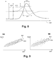
- Figure 9A by plotting the successive values (902) of this parameter as a function of time for a subject in the waking state, these are substantially aligned on a straight line (903). From the cloud of points thus acquired a forecast interval (904) is estimated, 90% of the measurement points being around this line (903) being within this range for a subject in the sleep state. The slope of this line and the width of the forecast interval, are functions of the subject, and for the same subject are likely to vary in time.
- Figure 9B when the same subject shows signs of decreased alertness, the variance of the AVR parameter increases, resulting in an increased number of points outside the forecast range corresponding to the fully awake subject.
- a scalar vigilance index is obtained by counting the number of values of the AVR out of the forecast interval defined for the awake subject, over the given measurement duration.
- Said forecast interval must be calculated for the individual.
- the line (903) and the forecast interval (904) are calculated from the last records of AVR when the subject is in a confirmed standby state, that is with a PERCLOS 80 ⁇ 3%, values recorded and updated in the memory means of the processing and calculation unit.
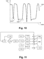
- An additional parameter derived from the accelerometer makes it possible to detect the micro-falls of the head, their frequency or their duration, these parameters being characteristic of a very advanced loss of vigilance.
- the accelerometer measures an acceleration of 1g corresponding to the gravity directed along the positive direction of the y axis.
- Figure 10 on a record showing the variation of the acceleration along the y-axis (1002) as a function of time (1002), during a significant loss of vigilance (1003, 1004) generating a micro-sleep, the head of the The individual falls forward according to the direction of the joint offering the least resistance. In the extended position, head fully bent forward, the orientation of the y axis relative to the gravity makes the projection of it on this axis is less than 1g, then again equal to 1g if the subject straight up the head. Thus, a micro-drop (1003, 1004) of the head is detected if the acceleration along the y-axis takes a value less than a threshold value (1005).
- the signal is initially filtered by a low-pass filter, with a relatively low cut-off frequency, of the order of 2 Hz in order to remove from the signal the shaking related to the activity of the individual. Only micro-drops are taken into account of significant duration, for example greater than 0.2 seconds.
- a scalar parameter is for example determined by the number of micro-falls found over a given measurement time.
- a second scalar parameter corresponds to the number of micro-drops of a greater duration (1004), for example of a duration greater than 0.5 or 1 second, counted on the same measurement interval or on a measurement interval more long.
- the principle of calculation of the composite index is similar whatever the critical situation whose detection is targeted, and some are the signals used, but uses different parameters depending on the type of detection.
- the parameters v are, according to exemplary embodiments and depending on the nature of the targeted detection, scalars or binaries, taking in the latter case the value 0 or 1 (or -1, +1) according to a pattern specific is detected or not in the signal.
- the parameters resulting from the processing of the signals of the sensors are scalar parameters, or bits, a function of time and denoted v 1 ( t ) ... v n ( t ).
- a and B are matrices of coefficients which are function of the individual and which weight the influence of each of the parameters v relatively to each other.
- V t 0 V 0 + B .
- the factors ⁇ and ⁇ as well as the combination equation of the parameters for the determination of the index evolve with the learning of the system, more particularly by the statistical analysis of the data at the server level (411, figure 4 ).
- a first alarm level corresponding, for example, to the detection of a beginning of loss of vigilance, leads to the activation of the light-emitting diode (282 ) continuously or flashing.
- a second level of alert corresponding to a more pronounced decrease of vigilance triggers the vibrator.
- a third level simultaneously triggers the diode and the buzzer, and if the system is configured in this way, sends a message to the connected devices in proximity to the object connected to the glasses.
- the method implementing the system object of the invention comprises a first step (1110) for controlling the wearing of the pair of glasses.
- This step aims to ensure the consistency of treatments performed but also to place the pair of glasses in standby mode if it is not used to reduce its power consumption.
- the port control step uses only the signals coming from the infrared receiver and applies to them a filtering and a treatment specific. If the test (1115) port is negative, the pair of glasses is put (1116) in standby mode.
- the wearing control of the glasses is made from the electrodes in contact with the skin of the user. If the glasses are worn, a finite impedance is measured between said electrodes when they are energized, an electrical circuit being established through the skin in contact with the electrodes. If the glasses are not worn, the electrical circuit is open and the impedance is infinite.
- a port test is performed regularly, for example every minute, in order to reactivate the active mode, if the wearing of glasses is detected.
- the acquisition of the signals (1120) is launched, this acquisition includes the filtering operations specific to each signal.
- the acquisition is performed at a frequency of 50 Hz and 150 Hz preferably around 70 Hz, which turns out to be a frequency to collect enough points to achieve the targeted treatments, while limiting power consumption.
- the signals thus conditioned are addressed to processing modules (1131, 1132, 1133, 1134) which extract the specific and representative scalar or binary parameters.
- one of the processing module (1131) is for example dedicated to the extraction of the parameters from the signals of the infrared receiver.
- Another processing module (1132) is for example dedicated to the extraction of the parameters resulting from the signals of the accelerometer or accelerometers,
- a third processing module (1133) is dedicated to the extraction of the parameters resulting from the signal of the barometric sensor and
- a fourth processing module (1134) is dedicated to the processing of signals from the electrodes.
- the parameters resulting from these processes are used to be combined into composite indices, during a calculation step implementing one or more modules, for example, a vigilance calculation module (1141) using the parameters defined from signal from the infrared reflector and according to one embodiment, at least one parameter derived from the processing of the accelerometer signal, a calculation module (1142) relating to the falls using the parameters derived from the processing of the accelerometer signals and according to one embodiment those from the barometric sensor, a calculation module (1143) relating to so-called soft falls, using parameters calculated from the accelerometer signals and the barometric sensor, a module of calculation (1144) relating to the recovery after fall, using the parameters resulting from the processing of the accelerometer signal, the signal of the infrared receiver and the signal coming from the barometric sensor, and a calculation module (1145) relating to the state of dehydration using the signals from the electrodes and according to one embodiment the signals from the infrared detector.
- a vigilance calculation module (1141) using the parameters defined
- Each calculation module thus defines a composite index relating to the critical situation whose detection is targeted.
- Each of these composite indices is compared with a threshold value stored in memory, namely a test (1151) for vigilance, a test (1142) for falls, a test (1153) for so-called soft falls (1153), a test (1154) for recovery after the fall and a test (1155) for the dehydration state.
- an alarm request is sent to an alarm management module (1161, 1162, 1163).
- a module (1161) for the management of alarms relating to the vigilance which according to the difference of the composite index with the threshold activates different alarm means, as described above.
- the functionalities of the system are adapted as needed by activating or loading the specific treatment modules.
- the main targeted functionality is vigilance monitoring, for example during the driving of a vehicle, and possibly the state of dehydration.
- the modules relating to the detection and treatment of the falls (1142, 1143, 1144, 1152, 1153, 1154, 1162) are not activated, although the information from the accelerometers is still used, in particular for the detection of micro-falls of the head.
- the modules triggering the alarms relating to the vigilance (1141, 1151, 1161) are not activated, which does not mean that the information from the infrared receiver is not used, they are particularly in the module of calculation (1144) of recovery after fall and in the module of evaluation of the state of dehydration.
- the detection of the wearing of glasses is obtained from the signals from the infrared receiver or signals from the electrodes.
- Figure 12A following the evolution of the intensity (1202) of the signal transmitted by the receiver as a function of time (1201) during the successive wearing and removal of the spectacles, when the spectacles are removed (1204, 1206), the Infrared beam emitted is not reflected by the eyelid or cornea and signal intensity is low. On the other hand, as soon as the glasses are worn correctly (1203, 1205, 1207), the reflection of the signal on the ocular zone very significantly increases the intensity of the signal.
- the signal from the infrared receiver is highly smoothed (1211) for example by means of a sliding average filter and exponential weighting.
- the obtained signal (1212) makes it possible to easily detect the withdrawal (1214) or reset (1213) events of the glasses.
- a threshold value (1220) is defined so that the glasses are worn correctly when the intensity of the signal (1211) thus strongly filtered takes values greater than this threshold value (1220).
- the port is considered to be incorrect when the measured impedance is greater than a defined threshold.
- This threshold depends on the frequency of the supply current, so the capacitance variations are more sensitive in a frequency range of the order of one kilohertz (ie between 1 kHz and 10 kHz) while the variations in resistance are more sensitive in a frequency range of the order of ten kilohertz (between 10 KHz and 100 KHz).
- the detection of the wearing of glasses uses a power supply of the electrodes in the kilohertz range, so as to limit the power consumption and thus measures a capacitance.
- the port detection combines the data from the infrared receiver and the data from the measurement of impedance between the electrodes.
- the glasses When the glasses are not worn, for example because they fell after a fall, or when they are not worn correctly, for example too far forward on the nose, where they do not rest on the two ears, the calculation of the parameters, not only those from the infrared receivers but also from other sensors is wrong. Also the correct wearing of glasses is important for a reliable detection and evaluation of a risk situation.
- the standby following the detection of a non-port or an incorrect port is progressive and, according to an exemplary embodiment, begins with the emission of a specific alarm on the light-emitting diode and the vibrator and possibly on the object connected to the glasses. Then, during periodic tests following the standby, a short alarm is triggered during each test if the non-port or the incorrect port are still detected, for example by a brief and simultaneous tripping of the diode and the vibrator, this during the tests carried out, for example, within 15 minutes after the standby. Beyond this time, the system goes into deeper sleep and no longer generates an alarm.
- Figure 13 for the detection of simple drops, the calculation of the parameters uses the accelerometer signals.
- the signals are initially filtered by a low-pass filter with a relatively low cut-off frequency, for example 0.1 Hz, in order to eliminate the vibration phenomena corresponding to the current activities.
- a second filtering is applied in the form of a sliding medium filter, preferably of order 3, this type of filtering makes it possible to eliminate the random noise while preserving the sharpness of the peaks.
- Figure 13A given the positioning of the accelerometer, gravity being oriented along the positive y axis, a first major effect of a fall is detected by a fall in the acceleration measured along the y axis.
- a simple accelerometer measuring the acceleration in only one direction, in this case y, would be sufficient for a fall detection.
- the phenomenon described on the y axis is also detected on the sum of the accelerations along the three axes, and the use of a triaxial accelerometer makes it possible to improve the detection while offering other advantages, in particular in the detection of so-called soft falls.
- a fall event is characterized by the appearance of a first peak (1303) directed in the negative direction of the axis (1302) and which corresponds to the phenomenon of free fall.
- This first peak is quickly followed by a second peak (1304) directed in the positive direction of the axis (1302) and which corresponds to the impact of the body on the ground or any other obstacle.
- the presence of two consecutive inverted peaks in a given time window and each exceeding a threshold value (1305, 1306) is a specific detectable pattern in the sum of the accelerations of the sensors, indicating a fall.
- the low threshold value is set at 0.6g (5.89 ms -2 ) and the high threshold value (1306), corresponding to the impact, is set at 2g (19.62 ms - 2 ).
- the Figure 13B represents the evolution of the value (1312) of the time derivative of the signal from the barometric sensor as a function of time (1301) during a fall episode followed by a recovery of the person.
- a first peak (1313) corresponds to the fall, that is to say the loss of altitude resulting in an increase in pressure. The subject then remains for some time on the ground, the pressure stabilizes, then it rises, which corresponds to a second peak (1314) of pressure reduction or increase of altitude.
- a parameter for characterizing a fall is determined in the form of a binary parameter, corresponding to the presence of a peak (1313) in the derivative of the barometric pressure whose amplitude exceeds a certain threshold.
- a fall of one meter in free fall implies a variation of pressure of 12 Pa over a duration of approximately 0.3 seconds. A fall is rarely totally free so that the threshold value is for example set between 10 Pas -1 and 20 Pas -1 .
- This parameter is a binary parameter corresponding to the detection or not of such a pattern over a given time interval.
- an additional fall characterization parameter is a binary parameter indicating the presence of a peak of recovery in a given time interval after the peak of fall on the derivative of the barometric signal.
- an additional parameter, of scalar type, corresponding to the time (1317) separating the peak of fall (1313) of the peak of bearing (1314) can also be used to characterize the severity of the fall.
- the treatment principle explained above is effective for detecting a fall involving a phenomenon, even a short one, of free fall, observed in the case of an accidental fall or in the case of sudden loss of consciousness.
- the fall may be caused, for example, by a progressive loss of knowledge, leading to a so-called soft fall, which does not make it possible to detect a phenomenon of free fall.
- a soft drop is characterized by the presence of a peak of impact detected on the sum of the accelerations with a lower threshold value than in the case of a free fall, and likewise, by a positive peak in the derivative of the barometric signal, detected for a lower threshold value.
- These two parameters are binary parameters accounting for the presence of such peaks in the measurement interval.
- Figure 14A unlike a situation of everyday life like sitting in an armchair, a fall, even a soft one, implies a loss of verticality.
- the position of the glasses, on the head is particularly advantageous for measuring such a loss of verticality.
- the loss of verticality is for example measured by the value of the resulting acceleration in plane perpendicular to gravity, the axes x and z with reference to the figure 2 .
- the plot of the intensity of the acceleration (1402) in the plane perpendicular to the gravity as a function of time (1401) during a soft fall episode clearly shows one or more peaks (1403) greater than a threshold value (1404) which are thus detectable and whose detection over the acquisition period is captured in a binary parameter. These parameters are combined in a composite index to detect a soft drop and generate an alert.
- the combination of these parameters does not allow to detect and characterize a soft fall in which the head remains substantially vertical, this is the case for example in the case of a fall while the subject is backed against a wall, or other complex situations, and can lead to false negatives.
- the complete algorithm for the detection and characterization of falls takes into account parameters determined in the moments following the fall and which in general attest to the recovery, or not, of the subject.
- the determination of the posture of the person is determined for example by the values of accelerometry on the various axes.
- the accelerometer is only subjected to the action of gravity, which when the head is straight is projected along the y axis of the figure 2 .
- the orientation of the head is determined.
- This orientation is for example defined by an angle opposite the theoretical vertical position.
- the value of this angle is a scalar parameter, symptomatic of the posture and activity of the person after the fall.
- the activity of the person is, for example, also measured by the accelerometer. If the person moves, acceleration variations are observed.
- the amplitude of variation of the accelerations over a given time interval measured for example by the variance of the acceleration signal on this interpolation time, is a symptomatic scalar parameter of the activity of the person.
- the pair of glasses falls from the face of the person or is in an incorrect position on the latter following the fall.
- the parameters making it possible to characterize the fall by the behavior of the subject in the moments following the fall are not measurable, or are measured in error.
- the generation of an alarm based on the parameters evaluated after the incident includes a verification of the wearing of glasses. If the non-port or an incorrect port is detected, an alarm is generated and repeated for a defined time, as long as the glasses are not delivered correctly. If after this set time, despite the alarms, the glasses are not given, then it is possible that the person is not able to put them back and an alarm is triggered.
- the dehydration state of an individual is determined by his rate of hydration, which gives the amount of water contained in his body in relation to his body mass.
- the system object of the invention When the rate of water mass falls below a certain value, which depends on the individual, the system object of the invention generates an alarm indicating that the person is in critical conditions vis-à-vis the dehydration.
- the transmitter and the infrared receiver are useful for assessing the water mass ratio by measuring the absorption of infrared light from circulating blood in the blood vessels of the eyelid or ocular sclera.
- the transmission power of the infrared transmitter is increased at regular time intervals, for example every 10 minutes, so as to measure the infrared absorption of the blood by means of the infrared receiver and thus to evaluate the level of dehydration of the person wearing the glasses of the system object of the invention.
- the reflectance of the cornea is also a function of the hydration of the eye which is itself dependent on the state of hydration of the individual.
- a composite index based on the combination of parameters calculated from the infrared absorption of the blood and the reflectance of the cornea is calculated to determine the hydric mass or the state of dehydration of the individual.
- infrared absorption of the blood and reflectance of the cornea which are measurable by the emitter and the infrared reflector in an embodiment where the glasses of the system object of the invention are provided, are strongly dependent on the individual. and require a calibration procedure.
- the impedance of the skin when it is traversed by an alternating current of low voltage and high frequency is also representative of the hydration state of an individual. These variations of impedance with the rate of water mass are reflected in capacitance variations and resistance variations.
- the impedance is in a range between 200 and 500 Ohms, depending on the characteristics of the current (voltage and frequency) but are not very dependent on the individual.
- an impedance threshold independent of the individual, and which serves for example to measure a relatively advanced state of dehydration, is defined and stored in memory.
- the impedance is measured for different frequencies, so in the range of the kilohertz it is essentially capacitance variations that are detected, whereas in the range of about ten kilohertz it is essentially variations in resistance that are detected.
- a composite index calculated from the impedance measurements made in the two frequency ranges allows detection of a dehydration state more reliably than using a single measurement.
- a composite index calculated according to the principles described above is calculated by combining the measurements from the infrared receiver and measurements of impedance between the electrodes.
- this composite index combines measures whose representative threshold is dependent on the individual, which require calibration, and measures whose representative threshold is independent of the individual.
- the glasses of the object system of the invention are preferably adapted and calibrated for their user.
- This adaptation comprises a mechanical adaptation, including branches and a calibration of the sensors, more particularly the accelerometer, the transmitter and the infrared receiver according to the sensors and modules which are equipped with the glasses.
- Calibration is performed by a professional, for example an optician, or by the user himself, guided for example by an application implanted in the smart phone connected to the glasses.
- the calibration of the accelerometer aims to accurately determine the gain on each of the axes and the rotation matrix so that the acceleration of gravity is oriented along the y axis when the user wears the glasses in a position considered as corresponding to verticality. According to an exemplary embodiment, this calibration is carried out from 3 acquisitions under defined conditions.
- the glasses are placed perfectly horizontal in the wearing position, for example in a mounting specially adapted for this purpose. Under these conditions, the y- axis is supposed to measure an acceleration of 1g positive.
- the glasses are placed perfectly horizontal, in a position returned with respect to the wearing position, for example in a suitable support. In this configuration, the y- axis is supposed to measure an acceleration of -1g.
- the glasses are worn by their user in the right head position. The analysis of the three measurements made under these conditions makes it possible to calibrate the accelerometer.
- the calibration of the infrared receiver makes it possible to fix the parameters, in particular the threshold value in the signal intensity, making it possible to differentiate the voluntary blinks from the spontaneous blinks.
- the user wears the glasses for a predetermined period, for example 1 minute, during which he performs a voluntary blinking of the two eyes at defined intervals for example every 10 seconds.
- the system adjusts these parameters, which must lead to the detection of 6 voluntary blinking peaks and between 10 and 20 spontaneous blinking peaks.
- the subject To calibrate the transmitter and infrared receiver vis-à-vis the measurement of the dehydration, the subject must be well hydrated which can be verified via the measurement of the impedance between the electrodes, in order to validate the conditions.
- the transmitting power of the infrared transmitter for the purpose of measurement on the ocular sclera or on the eyelid is set, within safe limits, and the value received on the infrared receiver is stored in memory.
- the value of the reflectance on the cornea is also set, but for a nominal power of emission of the infrared transmitter, corresponding to the transmission power used for the detection of the palpebral movements and the value is also stored in memory.
Applications Claiming Priority (3)
| Application Number | Priority Date | Filing Date | Title |
|---|---|---|---|
| FR1771325A FR3074675B3 (fr) | 2017-12-07 | 2017-12-07 | Systeme personnel pour la detection d’une situation a risque et d’alerte |
| US201862667515P | 2018-05-05 | 2018-05-05 | |
| US16/178,365 US10964190B2 (en) | 2016-05-31 | 2018-11-01 | Personal system for the detection of a risky situation and alert |
Publications (1)
| Publication Number | Publication Date |
|---|---|
| EP3494872A1 true EP3494872A1 (de) | 2019-06-12 |
Family
ID=64661067
Family Applications (1)
| Application Number | Title | Priority Date | Filing Date |
|---|---|---|---|
| EP18210290.5A Pending EP3494872A1 (de) | 2017-12-07 | 2018-12-05 | Persönliches physiologisches warnsystem |
Country Status (1)
| Country | Link |
|---|---|
| EP (1) | EP3494872A1 (de) |
Cited By (1)
| Publication number | Priority date | Publication date | Assignee | Title |
|---|---|---|---|---|
| WO2022243640A1 (fr) * | 2021-05-20 | 2022-11-24 | Didier Jacquet | Procede et dispositif d'aide a l'analyse de posture d'un cavalier et/ou d'une monture |
Citations (8)
| Publication number | Priority date | Publication date | Assignee | Title |
|---|---|---|---|---|
| FR12000E (fr) | 1909-02-08 | 1910-06-10 | Schneider & Cie | Lunette à objectif tournant |
| US20010028309A1 (en) * | 1996-08-19 | 2001-10-11 | Torch William C. | System and method for monitoring eye movement |
| US20090105605A1 (en) * | 2003-04-22 | 2009-04-23 | Marcio Marc Abreu | Apparatus and method for measuring biologic parameters |
| EP2061026A1 (de) * | 2006-09-08 | 2009-05-20 | Sony Corporation | Anzeigeeinrichtung und anzeigeverfahren |
| US20100134761A1 (en) * | 2005-08-11 | 2010-06-03 | Sleep Diagnostics Pty Ltd | Alertness sensing spectacles |
| US20130197856A1 (en) * | 2011-06-17 | 2013-08-01 | James R. Barfield | Method and system for discerning a false positive in a fall detection signal |
| US20170231490A1 (en) * | 2014-08-10 | 2017-08-17 | Autonomix Medical, Inc. | Ans assessment systems, kits, and methods |
| FR3051656A1 (fr) * | 2016-05-31 | 2017-12-01 | Ellcie Healthy | Dispositif connecte de suivi comportemental d'un individu et permettant la detection et/ou la prevention d'une anomalie |
-
2018
- 2018-12-05 EP EP18210290.5A patent/EP3494872A1/de active Pending
Patent Citations (9)
| Publication number | Priority date | Publication date | Assignee | Title |
|---|---|---|---|---|
| FR12000E (fr) | 1909-02-08 | 1910-06-10 | Schneider & Cie | Lunette à objectif tournant |
| US20010028309A1 (en) * | 1996-08-19 | 2001-10-11 | Torch William C. | System and method for monitoring eye movement |
| US20090105605A1 (en) * | 2003-04-22 | 2009-04-23 | Marcio Marc Abreu | Apparatus and method for measuring biologic parameters |
| US20100134761A1 (en) * | 2005-08-11 | 2010-06-03 | Sleep Diagnostics Pty Ltd | Alertness sensing spectacles |
| EP2061026A1 (de) * | 2006-09-08 | 2009-05-20 | Sony Corporation | Anzeigeeinrichtung und anzeigeverfahren |
| US20130197856A1 (en) * | 2011-06-17 | 2013-08-01 | James R. Barfield | Method and system for discerning a false positive in a fall detection signal |
| US20170231490A1 (en) * | 2014-08-10 | 2017-08-17 | Autonomix Medical, Inc. | Ans assessment systems, kits, and methods |
| FR3051656A1 (fr) * | 2016-05-31 | 2017-12-01 | Ellcie Healthy | Dispositif connecte de suivi comportemental d'un individu et permettant la detection et/ou la prevention d'une anomalie |
| WO2017207925A1 (fr) * | 2016-05-31 | 2017-12-07 | Ellcie-Healthy | Dispositif connecté de suivi comportemental d'un individu et permettant la détection et/ou la prévention d'une anomalie |
Cited By (2)
| Publication number | Priority date | Publication date | Assignee | Title |
|---|---|---|---|---|
| WO2022243640A1 (fr) * | 2021-05-20 | 2022-11-24 | Didier Jacquet | Procede et dispositif d'aide a l'analyse de posture d'un cavalier et/ou d'une monture |
| FR3123000A1 (fr) * | 2021-05-20 | 2022-11-25 | Didier Jacquet | Procédé et dispositif d’aide à l’analyse de posture d’un cavalier et/ou d’une monture |
Similar Documents
| Publication | Publication Date | Title |
|---|---|---|
| US10152869B2 (en) | Personal system for the detection of a risky situation and alert | |
| US10964190B2 (en) | Personal system for the detection of a risky situation and alert | |
| EP3060958B1 (de) | Vorrichtung und verfahren zur bestimmung eines schreib- oder lesemodus | |
| US10694981B2 (en) | Wearable physiology monitor computer apparatus, systems, and related methods | |
| CN107870451B (zh) | 用于眼镜架的配戴式检测模块 | |
| US11222519B2 (en) | Personal system for the detection of a risky situation, more particularly of a fall prone situation | |
| US20220139188A1 (en) | Personal system for the detection of a fall or a fall prone situation | |
| FR3048542A1 (fr) | Dispositif et methode de surveillance personnalises d'un conducteur d'un vehicule automobile | |
| US20220238220A1 (en) | Headset integrated into healthcare platform | |
| EP4003149A1 (de) | System und verfahren zur erkennung und unterstützung der korrektur von unangemessenen haltungen in echtzeit | |
| US20140088667A1 (en) | Anti-sleep glasses | |
| EP3590421A1 (de) | Verfahren und vorrichtung zur überwachung der kapazität eines crewmitglieds eines luftfahrzeugs | |
| EP3494872A1 (de) | Persönliches physiologisches warnsystem | |
| EP3409198B1 (de) | Verfahren zur detektion einer gefahren- oder alarmsituation | |
| EP2448465B1 (de) | Kennzeichnung der wahrnehmung einer unschärfe | |
| WO2009134784A2 (en) | Real time system for readiness monitoring of dismounted soldiers | |
| FR3077980A3 (fr) | Système personnel d’alerte physiologique | |
| EP3866100A1 (de) | System zur aktualisierung eines indexes einer person | |
| FR3074675A3 (fr) | Systeme personnel pour la detection d’une situation a risque et d’alerte | |
| WO2016131927A1 (en) | Method, electronic device and system for monitoring a skin surface condition | |
| WO2021234174A1 (fr) | Procédé pour la détection de la toux par mesure inertielle | |
| EP2739498A1 (de) | System und verfahren zur vorhersage der schläfrigkeit des fahrers eines fahrzeuges | |
| US20230240606A1 (en) | Monitoring Psychomotor Performance Based on Eyelid Tracking Information | |
| FR3118210A3 (fr) | Procédé et système de diagnostic de l’inadaptation d’une pièce à une caractéristique morphologique d'un utilisateur de cette pièce | |
| EP4245221A1 (de) | Elektronische vorrichtung zur überwachung eines neurophysiologischen zustands eines bedieners in einer steuerstation eines flugzeugs, überwachungsverfahren und computerprogramm dafür |
Legal Events
| Date | Code | Title | Description |
|---|---|---|---|
| PUAI | Public reference made under article 153(3) epc to a published international application that has entered the european phase |
Free format text: ORIGINAL CODE: 0009012 |
|
| STAA | Information on the status of an ep patent application or granted ep patent |
Free format text: STATUS: THE APPLICATION HAS BEEN PUBLISHED |
|
| AK | Designated contracting states |
Kind code of ref document: A1 Designated state(s): AL AT BE BG CH CY CZ DE DK EE ES FI FR GB GR HR HU IE IS IT LI LT LU LV MC MK MT NL NO PL PT RO RS SE SI SK SM TR |
|
| AX | Request for extension of the european patent |
Extension state: BA ME |
|
| STAA | Information on the status of an ep patent application or granted ep patent |
Free format text: STATUS: REQUEST FOR EXAMINATION WAS MADE |
|
| 17P | Request for examination filed |
Effective date: 20191212 |
|
| RBV | Designated contracting states (corrected) |
Designated state(s): AL AT BE BG CH CY CZ DE DK EE ES FI FR GB GR HR HU IE IS IT LI LT LU LV MC MK MT NL NO PL PT RO RS SE SI SK SM TR |
|
| STAA | Information on the status of an ep patent application or granted ep patent |
Free format text: STATUS: EXAMINATION IS IN PROGRESS |
|
| 17Q | First examination report despatched |
Effective date: 20220706 |
|
| 19U | Interruption of proceedings before grant |
Effective date: 20230210 |
|
| 19W | Proceedings resumed before grant after interruption of proceedings |
Effective date: 20240301 |
|
| RAP3 | Party data changed (applicant data changed or rights of an application transferred) |
Owner name: EURO PROTECTION SURVEILLANCE |