EP3494632B1 - Motorkomponente, primärteil und linearmotor - Google Patents
Motorkomponente, primärteil und linearmotor Download PDFInfo
- Publication number
- EP3494632B1 EP3494632B1 EP17777252.2A EP17777252A EP3494632B1 EP 3494632 B1 EP3494632 B1 EP 3494632B1 EP 17777252 A EP17777252 A EP 17777252A EP 3494632 B1 EP3494632 B1 EP 3494632B1
- Authority
- EP
- European Patent Office
- Prior art keywords
- heat sink
- laminated core
- grooves
- motor component
- motor
- Prior art date
- Legal status (The legal status is an assumption and is not a legal conclusion. Google has not performed a legal analysis and makes no representation as to the accuracy of the status listed.)
- Active
Links
Images

Classifications
-
- H—ELECTRICITY
- H02—GENERATION; CONVERSION OR DISTRIBUTION OF ELECTRIC POWER
- H02K—DYNAMO-ELECTRIC MACHINES
- H02K9/00—Arrangements for cooling or ventilating
- H02K9/14—Arrangements for cooling or ventilating wherein gaseous cooling medium circulates between the machine casing and a surrounding mantle
- H02K9/18—Arrangements for cooling or ventilating wherein gaseous cooling medium circulates between the machine casing and a surrounding mantle wherein the external part of the closed circuit comprises a heat exchanger structurally associated with the machine casing
-
- H—ELECTRICITY
- H02—GENERATION; CONVERSION OR DISTRIBUTION OF ELECTRIC POWER
- H02K—DYNAMO-ELECTRIC MACHINES
- H02K41/00—Propulsion systems in which a rigid body is moved along a path due to dynamo-electric interaction between the body and a magnetic field travelling along the path
- H02K41/02—Linear motors; Sectional motors
- H02K41/03—Synchronous motors; Motors moving step by step; Reluctance motors
-
- H—ELECTRICITY
- H02—GENERATION; CONVERSION OR DISTRIBUTION OF ELECTRIC POWER
- H02K—DYNAMO-ELECTRIC MACHINES
- H02K15/00—Processes or apparatus specially adapted for manufacturing, assembling, maintaining or repairing of dynamo-electric machines
- H02K15/02—Processes or apparatus specially adapted for manufacturing, assembling, maintaining or repairing of dynamo-electric machines of stator or rotor bodies
- H02K15/028—Fastening stator or rotor bodies to casings, supports, shafts or hubs
-
- H—ELECTRICITY
- H02—GENERATION; CONVERSION OR DISTRIBUTION OF ELECTRIC POWER
- H02K—DYNAMO-ELECTRIC MACHINES
- H02K9/00—Arrangements for cooling or ventilating
- H02K9/22—Arrangements for cooling or ventilating by solid heat conducting material embedded in, or arranged in contact with, the stator or rotor, e.g. heat bridges
- H02K9/227—Heat sinks
-
- H—ELECTRICITY
- H02—GENERATION; CONVERSION OR DISTRIBUTION OF ELECTRIC POWER
- H02K—DYNAMO-ELECTRIC MACHINES
- H02K9/00—Arrangements for cooling or ventilating
- H02K9/19—Arrangements for cooling or ventilating for machines with closed casing and closed-circuit cooling using a liquid cooling medium, e.g. oil
- H02K9/197—Arrangements for cooling or ventilating for machines with closed casing and closed-circuit cooling using a liquid cooling medium, e.g. oil in which the rotor or stator space is fluid-tight, e.g. to provide for different cooling media for rotor and stator
Definitions
- the invention relates to a motor component for a linear motor, in particular a primary part or a stator according to the preamble of claim 1, a primary part according to the preamble of claim 14 and a linear motor according to the preamble of claim 15.
- the document DE 11 2009 000359 discloses a corresponding engine component.
- the object of the invention is to be able to propose a motor component for a linear motor that can provide reliable cooling and can still be produced inexpensively.
- the task is solved, starting from a motor component, a primary part or a linear motor of the type mentioned, by the characterizing features of claim 1.
- the motor component according to the invention for a linear motor initially comprises a laminated core and a heat sink.
- a motor component can in particular be a primary valley or a stand.
- This primary part further comprises windings and/or permanent magnets for forming a magnetic field, with which a movable part of the linear motor is ultimately driven, which is present, for example, in the form of a secondary part.
- a laminated core usually consists of assembled individual sheets that are electrically insulated from each other in order to avoid eddy currents that could be generated inductively if a corresponding body, which is intended to guide the field lines and strengthen the magnetic field, were made of a ferromagnetic solid material .
- the coils or windings and/or corresponding permanent magnets are arranged in grooves in the laminated core.
- the invention is characterized in that the heat sink is connected to the laminated core and arranged parallel to the arrangement of the grooves, the laminated core and the heat sink being glued together.
- the arrangement in a plane parallel to the grooves makes it possible for the heat sink to be arranged close to the respective windings, possibly also at a constant or essentially constant distance from the windings, so that a homogeneous Cooling is made possible.
- particularly cost-effective production can be achieved because the two parts, the laminated core and the heat sink, can be manufactured as separate parts, so that corresponding cooling channels do not have to be manufactured in the material consisting of individual sheets, which is comparatively complex.
- the materials can be connected to one another in a simple manner, but still without air gaps or other circumstances that impede heat conduction.
- connection between the laminated core and the heat sink is surprisingly made possible by gluing, the gluing being carried out in particular with a very thin adhesive layer.
- the distance between the laminated core and the heat sink can be very small, which promotes good heat dissipation, and on the other hand, it enables a very stable connection between the laminated core and the heat sink to be achieved.
- it can also withstand very high forces that generally act on an active part of an engine during operation.
- air gaps between the heat sink laminated core can be avoided.
- some adhesives can also have poor thermal conductivity properties, in the present case it proves to be advantageous that the adhesive layer itself can only be made very thin and therefore the thermal resistance caused by it is rather low.
- At least one of the two, or both can be designed as a plate, so that heat sink channels and windings arranged in the grooves of the laminated core run in parallel planes as a heat source can. Furthermore, a small distance between the channels and the windings is made possible, so that overall good and uniform heat dissipation is possible.
- the laminated core and heat sink are connected to one another in a sandwich construction.
- it also makes it possible to increase mechanical rigidity because the corresponding "sandwich layers" stabilize each other and ensure a higher bending moment or area moment of inertia.
- there are further advantages over a conventional construction according to the prior art which often provides for the primary part to be fully cast; According to the prior art, it has proven to be disadvantageous that air pockets can often be found in the casting material.
- the laminated core can, in particular in an embodiment variant of the invention, be designed as a baking varnish laminated core in order to increase the mechanical rigidity.
- at least one baking varnish winding can be arranged in the grooves, which is cast, so that the mechanical rigidity can also be increased in this way.
- conventionally insulated winding wire is also used instead of wire coated with baking varnish.
- orthocyclically wound baking varnish coils are provided as windings.
- round wire is often used, which has a round cross-section; In principle, however, a square wire can also be used, for example.
- the cross section can play a role in particular when it comes to achieving the densest possible winding packing. By packing the windings as densely as possible, the highest possible fields can be achieved while requiring as little space as possible are generated, which can increase the performance of the engine.
- the heat sink has at least one channel for conducting coolant.
- Water for example, can be used as a coolant.
- such a cooling channel can advantageously be arranged in such a way that it passes through the surface of the heat sink, which is parallel to the plane in which the grooves are arranged, as evenly and densely as possible, so that heat dissipation is as uniform and uniform as possible can.
- such a cooling channel in a plate can have a meandering course. It is also conceivable that several cooling channels pass through the plate.
- corresponding heat sink is not traversed by cooling channels in a straight path, it is advantageous to mill corresponding cooling channels into the plate, for example, in particular parallel to the plane in which the notes are arranged.
- a cover In order to seal the cooling channels tightly, in such a case a cover must be provided which is attached to the side of the plate or heat sink on which the open sections of the cooling channels are located.
- the lid can be manufactured inexpensively as a single part.
- a temperature-resistant adhesive is preferably used, since relatively high temperatures can sometimes be reached during operation of the engine and it is precisely then that it is necessary that there is still good mechanical cohesion between them Heat sink and sheet metal package is present. For this reason, for example, various temperature-resistant adhesives can be used, in particular a two-component adhesive based on epoxy resin. In order to produce a stable layer that has a low thermal resistance, an adhesive layer with a maximum thickness of 0.25 mm can in particular be provided.
- the heat sink is made of aluminum according to the invention.
- this material is comparatively inexpensive.
- cooling channels are restricted in the heat sink
- this open area of the cooling channels must be covered, which can be done, for example, using a cover.
- the cover is also made of aluminum, since the cover and heat sink have the same or at least a very similar coefficient of thermal expansion when heated and accordingly both also change when heated at the same time behave the same and there are no mechanical stresses.
- a lid is a cost-effective option to cover and close all of the cooling channels.
- the lid can be made from a flat sheet of metal, for example. In this case, it may not be sufficient to simply attach the cover to the edges of the heat sink, as is often provided in the prior art.
- the cover is attached to the plate of the heat sink by friction stir welding in order to be able to increase the mechanical stability at high pressures of the coolant flowing through the channel and also the mechanical rigidity.
- the cover is fastened to the plate of the heat sink in such a way that the at least one channel is at least partially, in particular completely, surrounded by the welding path. This means that when the cooling channel sections are parallel, there is usually at least a welding path between them.
- the welding pin of the welding tool is turned or rotated and pressed into the material until the welding shoulder rests on the material. While the welding pin continues to rotate, the welding tool is guided along the welding path to be welded, whereby the material is put into a doughy state, i.e. it becomes plastic and can be processed.
- a fine-grained connection area is created between the two workpieces that are to be connected to one another.
- only a small amount of heat is introduced, so that the workpiece is protected, while excellent, very stable connection properties can be achieved.
- a primary part according to the invention or a linear motor according to the invention are characterized in that a corresponding motor component according to the invention or, in the case of a linear motor, a corresponding primary part according to the invention or according to one of the exemplary embodiments are used, so that the advantages already mentioned above can be achieved.
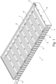
- Figure 1 shows a schematic sectional view through a primary part 1 of a linear motor with a laminated core 2 and a heat sink 3.
- Both laminated core 2 and heat sink 3 are each designed as plates that were glued to one another in a sandwich construction.
- the adhesive layer is designated by the reference number 4:
- a cooling channel 7 is milled into the heat sink 3, which has a substantially meandering course and passes through practically the entire surface of the heat sink 3.
- holes 8 are provided in the heat sink.
- the windings 6 can be provided as orthocyclically wound baked varnish coils, for example with a round wire. This measure enables high packing density.
- the sheet metal package 2 can also be designed as a baking varnish package. The use of baking varnish for the laminated core 2 and the windings 6 makes it possible to achieve a high level of mechanical rigidity.
- laminated core 2 and heat sink 3 are combined into one part, with the adhesive layer 4, through which both are connected to one another, being very thin.
- the adhesive layer 4 By applying the adhesive over a large area and therefore choosing a very large adhesive surface, a high degree of stability of this connection between the laminated core 2 and the heat sink 3 is achieved.
- the sandwich construction itself enables a high degree of mechanical stability Stiffening. Even if the corresponding engine components are exposed to high forces, the design is still particularly stable.
- there is a very compact design which, on the one hand, makes the best possible use of the available space and can therefore be integrated very well into different machines. In this case, the compact design usually also has a positive effect on mechanical rigidity and stability.
- the plane in which the grooves 5 are arranged is parallel to the plane in which the cooling channels 7 are located.
- the present sandwich construction makes it possible for cooling channels 7 and grooves 5 to be at a comparatively small distance from one another.
- the entire area above the surface in which the grooves 5 are arranged is essentially evenly penetrated by cooling channels 7. Due to this, particularly good heat dissipation can also be achieved through the adhesive layer 4, which is only very thin anyway.
- the cooling surface is, so to speak, maximized.
- the heat sink 3 out of aluminum a high level of thermal conductivity is achieved.
- the distance to the windings 6, which represent the heat source, is kept as small as possible.
- the particularly good cooling also ensures that there is no excessive heat transfer to other components of the machine in which the motor component or the corresponding linear motor is used.
- the simple gluing of heat sink 3 and laminated core 2 together enables simple assembly and cost-effective production. Furthermore, the linear motor does not have to be manufactured by hand; at least partially automated production is also possible.
- FIG. 2 shows again the same view as Figure 1 , but not as a sectional view.
- the entire course of the cooling channels 7, in particular their meandering course over the surface of the heat sink 3, is visible.
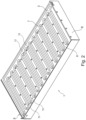
- FIG 3 Again, the same view can be seen, but here the cover 10 is attached to the heat sink 3.
- the cover 10 in turn covers the cooling channels 7 and seals them at the top in the drawing.
- the cover 10 is applied and fastened to the heat sink 3 by friction stir welding.
- the welding path can be arranged in particular between the meandering loops of the cooling channels 7.
- These areas are in Figure 2 marked with the reference number 11 as an example.
- the process of friction stir welding enables a very strong and stable cohesive connection between the cover 10 and the heat sink 3, so that the cooling channels 7 can also be under high pressure from the coolant (approximately on the order of 6 bar). In this way, a high level of bending rigidity is also achieved.
- the heat sink is connected to the laminated core and arranged parallel to the arrangement of the grooves, with the laminated core and the heat sink being glued together.
- This technical measure surprisingly enables a particularly stable structure with good heat dissipation, because it would generally be expected that with the high attractive forces that act on an active part of a linear motor and are in the order of 20 kN to 30 kN, a Adhesive connection would be too unstable, although, as it turns out in connection with the invention, the opposite is the case.
- the particularly simple assembly also enables a reduction in assembly time, which also has an advantageous effect on assembly costs.
- the invention also surprisingly enables a high degree of economy and cost savings in production, since, in contrast to the prior art, laminated cores, heat sinks, etc. can be manufactured comparatively inexpensively as individual components. This cost saving can also compensate for the higher costs that may currently be incurred (as a result of friction stir welding) even in an embodiment of the invention in which the cover is connected to the heat sink by friction stir welding.
Landscapes
- Engineering & Computer Science (AREA)
- Power Engineering (AREA)
- Physics & Mathematics (AREA)
- Chemical & Material Sciences (AREA)
- Combustion & Propulsion (AREA)
- Electromagnetism (AREA)
- Manufacturing & Machinery (AREA)
- Motor Or Generator Cooling System (AREA)
- Iron Core Of Rotating Electric Machines (AREA)
Description
- Die Erfindung betrifft eine Motorkomponente für einen Linearmotor, insbesondere ein Primärteil bzw. einen Ständer nach dem Oberbegriff des Anspruchs 1, ein Primärteil nach dem Oberbegriff des Anspruchs 14 sowie einen Linearmotor nach dem Oberbegriff des Anspruchs 15.
- Für Linearmotoren werden im Stand der Technik verschiedene Kühlungen vorgeschlagen. Aus der
DE 10 2007 020 057 A1 ist zum Beispiel ein Linearmotor mit integrierter Kühlung bekannt, wobei die Kühlung durch Kühlkanäle erreicht wird, die in das mit Nuten für die Wicklungen versehene Blechpaket eingearbeitet sind, d.h. die entsprechenden Einzelbleche des Blechpakets sind hier so ausgebildet, dass diese im zusammengefügten Zustand die entsprechenden Kühlkanäle ausbilden. - Das Dokument
DE 11 2009 000359 offenbart eine entsprechende Motorkomponente. - Aufgabe der Erfindung ist es, eine Motorkomponente für einen Linearmotor vorschlagen zu können, die eine zuverlässige Kühlung bereitstellen kann und dennoch kostengünstig herstellbar ist.
- Die Aufgabe wird, ausgehend von einer Motorkomponente, einem Primärteil bzw. einem Linearmotor der eingangs genannten Art, durch die kennzeichnenden Merkmale des Anspruchs 1 gelöst.
- Durch die in den abhängigen Ansprüchen genannten Maßnahmen sind vorteilhafte Ausführungen und Weiterbildungen der Erfindung möglich.
- Dementsprechend umfasst die erfindungsgemäße Motorkomponente für einen Linearmotor zunächst ein Blechpaket und einen Kühlkörper. Bei einer derartigen Motorkomponente kann es sich insbesondere um ein Primärtal bzw. ein Ständer handeln. Dieses Primärteil umfasst weiterhin Wicklungen und/oder Permanentmagneten zur Ausbildung eines Magnetfeldes, mit dem schließlich ein bewegliches Teil des Linearmotors angetrieben wird, welches etwa in Form eines Sekundärteils vorliegt.
- Ein Blechpaket besteht in der Regel aus zusammengeführten Einzelblechen, die gegeneinander elektrisch isoliert sind, um Wirbelströme zu vermeiden, die induktiv darin erzeugt werden könnten, wenn ein entsprechender Körper, der die Feldlinien leiten und das magnetische Feld verstärken soll, aus einem ferromagnetischen Vollmaterial ausgebildet wäre. Die Spulen bzw. Wicklungen und oder entsprechende Permanentmagneten sind in Nuten im Blechpaket angeordnet.
- Die Erfindung zeichnet sich dadurch aus, dass der Kühlkörper mit dem Blechpaket verbunden und parallel zur Anordnung der Nuten angeordnet ist, wobei das Blechpaket und der Kühlkörper miteinander verklebt sind. Durch die Anordnung in einer Ebene parallel zu den Nuten wird ermöglicht, dass der Kühlkörper nahe an den jeweiligen Wicklungen angeordnet sein kann, gegebenenfalls auch mit konstantem bzw. im Wesentlichen gleich bleibenden Abstand zu den Wicklungen, sodass eine homogene Kühlung ermöglicht wird. Darüber hinaus kann eine besonders kostengünstige Fertigung erzielt werden, weil die beiden Teile, das Blechpaket und der Kühlkörper als separate Teile gefertigt werden können, sodass entsprechende Kühlkanäle nicht in dem aus Einzelblechen bestehenden Material gefertigt werden müssen, was vergleichsweise aufwendig ist. Zum anderen sind aufgrund dieser vorgeschlagenen Bauweise die Materialien auf einfache Weise, aber dennoch ohne Luftspalte oder sonstige, die Wärmeleitung behindernde Umstände miteinander verbindbar.
- Diese Verbindung zwischen Blechpaket und Kühlkörper wird überraschenderweise durch Verkleben ermöglicht, wobei das Verkleben insbesondere mit einer sehr dünnen Klebeschicht erfolgt. Zum einen kann dadurch der Abstand zwischen Blechpaket und Kühlkörper sehr gering ausfallen, was eine gute Wärmeabfuhr begünstigt, zum anderen wird dadurch ermöglicht, dass eine sehr stabile Verbindung zwischen Blechpaket und Kühlkörper erreicht wird. In überraschender Weise kann dieser auch sehr hohen Kräften standhalten, die im Betrieb im Allgemeinen auf ein Aktivteil eines Motors wirken. Außerdem können bei dem vorgeschlagenen Aufbau Luftspalte zwischen Kühlkörper Blechpaket vermieden werden. Obgleich grundsätzlich einige Klebstoffe durchaus auch schlechte Wärmeleiteigenschaften aufweisen können, erweist es sich im vorliegenden Fall als vorteilhaft, dass die Klebeschicht selbst nur sehr dünn ausgebildet werden kann und daher der durch sie verursachte Wärmewiderstand eher gering ausfällt.
- Um eine möglichst große Kontaktfläche zwischen Blechpaket und Kühlkörper zu erreichen, kann zumindest eine von beiden, oder es können beide, jeweils als Platte ausgebildet sein, sodass Kühlkörperkanäle und in den Nuten des Blechpakets angeordnete Wicklungen als Wärmequelle in parallelen Ebenen verlaufen können. Ferner wird auch ein geringer Abstand der Kanäle und der Wicklungen zueinander ermöglicht, sodass insgesamt eine gute und gleichmäßige Wärmeabfuhr ermöglicht wird.
- Erfindungsgemäß sind Blechpaket und Kühlkörper in Sandwich-Bauweise miteinander verbunden. Neben den kurzen Abständen zwischen wärmeerzeugenden Wicklungen und wärmeabführenden Kühlkanälen wird darüber hinaus ermöglicht, dass die mechanische Steifigkeit erhöht wird, da die entsprechenden "Sandwich-Schichten" sich gegenseitig stabilisieren und für ein höheres Biegemoment bzw. Flächenträgheitsmoment sorgen. Erfindungsgemäß bieten sich weitere Vorteile gegenüber einem herkömmlichen Aufbau nach dem Stand der Technik, der oftmals einen Vollverguss des Primärteils vorsieht; gemäß dem Stand der Technik hat es sich nämlich als nachteilig erwiesen, dass oftmals in dem Vergussmaterial Lufteinschlüsse zu finden sind.
- Das Blechpaket kann insbesondere bei einer Ausführungsvariante der Erfindung als Backlackblechpaket ausgebildet sein, um die mechanische Steifigkeit zu erhöhen. Zudem kann in den Nuten wenigstens eine Backlackwicklung angeordnet sein, welche vergossen ist, sodass auch hierdurch die mechanische Steifigkeit erhöht werden kann. Darüber hinaus ist es bei der Ausführungsform denkbar, dass anstelle von mit Backlack beschichtetem Draht auch konventionell isolierter Wickeldraht verwendet wird. Bei einem bevorzugten Ausführungsbeispiel sind orthozyklisch gewickelte Backlackspulen als Wicklungen vorgesehen. Im Übrigen wird oftmals zwar Runddraht verwendet, der also einen runden Querschnitt aufweist; es kann aber grundsätzlich zum Beispiel auch ein Vierkantdraht eingesetzt werden. Der Querschnitt kann insbesondere eine Rolle spielen, wenn es darum geht, eine möglichst dichte Wicklungspackung zu erreichen. Durch möglichst dicht gepackte Wicklungen können bei möglichst geringem Platzbedarf möglichst hohe Felder erzeugt werden, wodurch die Leistung des Motors gesteigert werden kann.
- Wie bereits oben erwähnt, weist der Kühlkörper erfindungsgemäß wenigstens einen Kanal zur Leitung von Kühlflüssigkeit auf. Als Kühlflüssigkeit kann beispielsweise Wasser verwendet werden. Ein derartiger Kühlkanal kann der Ausführungsbeispiel der Erfindung in vorteilhafter Weise so angeordnet werden, dass er möglichst gleichmäßig und dicht die Fläche des Kühlkörpers, die parallel zur Ebene liegt, in der die Nuten angeordnet sind, durchsetzen, sodass eine möglichst einheitliche und gleichmäßige Wärmeabfuhr erreicht werden kann. Beispielsweise kann ein solcher Kühlkanal in einer Platte einen mäandrierenden Verlauf aufweisen. Denkbar ist auch, dass mehrere Kühlkanäle die Platte durchsetzen.
- Insbesondere dann, wenn der entsprechende Kühlkörper nicht auf geradem Weg von Kühlkanälen durchsetzt wird, ist es vorteilhaft, entsprechende Kühlkanäle in die Platte zum Beispiel hinein zu Fräsen, insbesondere parallel zu der Ebene, in der die Noten angeordnet sind. Um die Kühlkanäle wiederum dicht abzuschließen, keinen solchen Fall ein Deckel vorgesehen sein, der auf der Seite der Platte bzw. des Kühlkörpers befestigt wird, auf der sich die offenen Abschnitte der Kühlkanäle befinden. Der Deckel kann kostengünstig als Einzelteil gefertigt werden.
- Um Blechpaket und Kühlkörper miteinander zu verbinden, wird vorzugsweise ein temperaturbeständiger Kleber verwendet, da zum Teil im Betrieb des Motors relativ hohe Temperaturen erreicht werden können und es gerade dann notwendig ist, dass dennoch ein guter mechanischer Zusammenhalt zwischen Kühlkörper und Blechpaket vorhanden ist. Aus diesem Grunde können zum Beispiel verschiedene temperaturbeständige Kleber eingesetzt werden, insbesondere ein Zweikomponentenkleber auf Epoxydharzbasis. Um eine stabile Schicht, die thermisch einen geringen Widerstand bedeutet, herzustellen, kann insbesondere eine Klebeschicht mit einer Dicke von maximal 0,25 mm vorgesehen sein.
- Zur guten Abfuhr von Wärme und um gleichzeitig ein vergleichbar geringes Gewicht der Motorkomponente zu erhalten, ist der Kühlkörper erfindungsgemäß aus Aluminium gefertigt. Darüber hinaus ist dieses Material vergleichsweise kostengünstig.
- Im Zusammenhang mit einer Ausführungsform, bei der die Kühlkanäle in den Kühlkörper eingeschränkt sind, wurde bereits erläutert, dass dieser offene Bereich der Kühlkanäle abgedeckt werden muss, was zum Beispiel mithilfe eines Deckels geschehen kann. Vor allem dadurch, dass der Kühlkörper selbst aus Aluminium gefertigt ist, ist es vorteilhaft, dass der Deckel ebenfalls aus Aluminium gefertigt ist, da so Deckel und Kühlkörper bei Erwärmung den gleichen oder zumindest einen sehr ähnlichen Wärmeausdehnungskoeffizienten aufweisen und sich dementsprechend beide bei gleicher Erwärmung auch gleich verhalten und es nicht zu mechanischen Spannungen kommt. Ein Deckel stellt eine kostengünstige Variante dar, um die Gesamtheit der Kühlkanäle abzudecken und zu verschließen.
- Wenn die Kühlkanäle allerdings von einer Flüssigkeit durchströmt werden, auf die ein hoher Druck wirkt, besteht grundsätzlich die Möglichkeit, dass sich der Deckel, insbesondere, wenn es sich um ein vergleichsweise dünnes Material bezogen auf den übrigen Kühlkörper handelt, nach oben hin wölbt. In der Regel kann der Deckel zum Beispiel aus einem flachen Blech gefertigt sein. In diesem Falle reicht es gegebenenfalls nicht aus, den Deckel an den Rändern des Kühlkörpers lediglich zu befestigen, wie dies insbesondere auch oft im Stand der Technik vorgesehen ist. Erfindungsgemäß ist der Deckel auf der Platte des Kühlkörpers durch Rührreibschweißen befestigt, um die mechanische Stabilität bei hohen Drücken der den Kanal durchströmenden Kühlflüssigkeit sowie ferner die mechanische Steifigkeit erhöhen zu können. Besonders bevorzugt ist eine Variante, bei welcher der Deckel auf der Platte des Kühlkörpers derartig befestigt ist, dass der wenigstens ein Kanal wenigstens teilweise, insbesondere vollständig vom Schweißpfad eingefasst ist. Dies bedeutet, dass bei parallel liegenden Kühlkanalabschnitten zwischen diesen in der Regel wenigstens teilweise auch ein Schweißpfad liegt.
- Beim Rührreibschweißen wird im der Schweißstift des Schweißwerkzeugs gedreht bzw. in Rotation versetzt und dabei in das Material gepresst, bis die Schweißschulter auf dem Material aufsitzt. Während sich der Schweißstift weiterdreht, wird das Schweißwerkzeug entlang des zu schweißenden Schweißpfads geführt, wobei das Material in einen teigigen Zustand versetzt, also plastisch wird und bearbeitbar ist. Es entsteht ein feinkörniger Verbindungsbereich zwischen beiden Werkstücken, die miteinander zu verbinden sind. In vorteilhafter Weise erfolgt nur ein geringer Wärmeeintrag, sodass das Werkstück geschont wird, während jedoch hervorragende, sehr stabile Verbindungseigenschaften erzielt werden können.
- Dementsprechend zeichnen sich ein erfindungsgemäßes Primärteil bzw. ein erfindungsgemäßer Linearmotor dadurch aus, dass eine entsprechende Motorkomponente gemäß der Erfindung bzw. bei einem Linearmotor ein entsprechendes Primärteil gemäß der Findung bzw. gemäß einem der Ausführungsbeispiele verwendet werden, sodass die bereits vorgenannten Vorteile erreicht werden können.
- Ein Ausführungsbeispiel der Erfindung ist in den Zeichnungen dargestellt und wird nachstehend unter Angabe weiterer Einzelheiten und Vorteile näher erläutert. Im Einzelnen zeigen:
- Figur 1:
- ein schematischen Schnitt durch ein Primärteil eines Linearmotors gemäß der Erfindung (ohne Deckel),
- Figur 2:
- eine schematische Darstellung des Primärteils aus
Figur 1 (ohne Deckel), sowie - Figur 3:
- eine schematische Darstellung des Primärteils aus den
Figuren 1 ,2 mit Deckel. -
Figur 1 zeigt eine schematische Schnittdarstellung durch ein Primärteil 1 eines Linearmotors mit einem Blechpaket 2 und einem Kühlkörper 3. Beide, Blechpaket 2 und Kühlkörper 3 sind jeweils als Platten ausgebildet, die in Sandwichbauweise aufeinander geklebt wurden. Die Klebeschicht ist mit dem Bezugszeichen 4 bezeichnet: Im Blechpaket 2 befinden sich Nuten 5, welche wiederum mit Wicklungen 6 versehen sind. Im Kühlkörper 3 wiederum ist ein Kühlkanal 7 eingefräst, der einen im Wesentlichen mäandrierenden Verlauf aufweist und praktisch die gesamte Oberfläche des Kühlkörpers 3 durchsetzt. Zur Befestigung des Primärteils 1 sind im Kühlkörper Bohrungen 8 vorgesehen. An den Stirnflächen des Primärteils eins befinden sich jeweils Abschlussbleche 9, die jeweils einen Teil des Gehäuses des Motors bilden. Durch diese Bleche 9 können auch Leitungen zur Energieversorgung der Wicklungen 6 durchgeführt werden. - Die Wicklungen 6 können als orthozyklisch gewickelte Backlackspulen vorgesehen sein, beispielsweise mit einem Runddraht. Diese Maßnahme ermöglicht eine hohe Packungsdichte. Auch das Blechpaket 2 kann als Backlackpaket ausgebildet sein. Die Verwendung von Backlack für das Blechpaket 2 und die Wicklungen 6 ermöglichen es, eine hohe mechanische Steifigkeit zu erreichen.
- In vorteilhafter Weise sind Blechpaket 2 und Kühlkörper 3 zu einem Teil vereint, wobei die Klebeschicht 4, durch welche beide miteinander verbunden sind, sehr dünn ausgebildet ist. Durch den großflächigen Auftrag des Klebers und die somit auch sehr groß gewählte Klebefläche wird ein hohes Maß an Stabilität dieser Verbindung zwischen Blechpaket 2 und Kühlkörper 3 erreicht. Darüber hinaus ermöglicht die Sandwichbauweise selbst wiederum ein hohes Maß an mechanischer Versteifung. Auch dann, wenn die entsprechenden Motorkomponenten hohen Kräften ausgesetzt sind, liegt dennoch eine besonders stabile Bauweise vor. Darüber hinaus liegt eine sehr kompakte Bauweise vor, die einerseits den zur Verfügung stehenden Raum möglichst gut ausnutzt und insgesamt daher in unterschiedliche Maschinen sehr gut integriert werden kann. Im vorliegenden Fall wirkt sich die kompakte Bauweise in der Regel auch positiv auf die mechanische Steifigkeit und Stabilität aus.
- Wie ebenfalls aus
Figur 1 hervorgeht, liegt die Ebene, in der die Nuten 5 angeordnet sind, parallel zu der Ebene, in der sich die Kühlkanäle 7 befinden. Die vorliegende Sandwichbauweise ermöglicht es, dass Kühlkanäle 7 und Nuten 5 in vergleichsweise geringem Abstand zueinander liegen. Der gesamte Bereich über der Fläche, in welcher die Nuten 5 angeordnet sind, ist im Wesentlichen gleichmäßig durch Kühlkanäle 7 durchsetzt. Aufgrund dessen kann auch eine besonders gute Wärmeabfuhr, auch durch die Klebeschicht 4, die ohnehin nur sehr dünn ausgebildet ist, erreicht werden. Die Kühloberfläche wird gewissermaßen maximiert. Durch die Ausbildung des Kühlkörpers 3 aus Aluminium wird wiederum ein hohes Maß an Wärmeleitfähigkeit erzielt. Der Abstand zu den Wicklungen 6, welche die Wärmequelle darstellen, wird möglichst gering gehalten. Die besonders gute Kühlung sorgt auch dafür, dass kein zu großer Wärmeübertrag auf weitere Komponenten der Maschine erfolgt, in welcher die Motorkomponente bzw. der entsprechende Linearmotor eingesetzt wird. - Die erzielten Vorteile, dass zum einen bei dem vorliegenden Ausführungsbeispiel der Erfindung eine hohe Packungsdichte vorliegt, zum anderen aber auch eine gute Wärmeabfuhr und Kühlung erreicht werden kann, führen dazu, dass die Dauerkraft des Motors im Vergleich zu herkömmlichen Linearmotoren aus dem Stand der Technik deutlich erhöht werden kann.
- Das einfache Zusammenkleben von Kühlkörper 3 und Blechpaket 2 ermöglicht wiederum eine einfache Montage und eine kostengünstige Fertigung. Im Übrigen muss der Linearmotor nicht von Hand gefertigt werden, sondern eine zumindest teilautomatisierte Fertigung ist ebenfalls möglich.
- Die Darstellung gemäß
Figur 2 zeigt noch einmal die gleiche Ansicht wieFigur 1 , jedoch nicht als Schnittdarstellung. Hier ist der gesamte Verlauf der Kühlkanäle 7, insbesondere deren über die Oberfläche des Kühlkörpers 3 hinweg mäandrierender Verlauf sichtbar. - Auch in
Figur 3 wiederum ist die gleiche Ansicht zu sehen, hier ist jedoch der Deckel 10 auf den Kühlkörper 3 aufgebracht. Der Deckel 10 wiederum verdeckt die Kühlkanäle 7 und dichtet diese in der Zeichnung nach oben hin ab. Um einen möglichst dichten Verlauf der Kühlkanäle 7 zu erreichen, ist der Deckel 10 durch Rührreibschweißen auf den Kühlkörper 3 aufgebracht und befestigt. Der Schweißpfad kann insbesondere zwischen den mäandrierenden Schlaufen der Kühlkanäle 7 angeordnet sein. Diese Bereiche sind inFigur 2 mit dem Bezugszeichen 11 beispielhaft gekennzeichnet. Der Prozess des Rührreibschweißens ermöglicht eine sehr feste und stabile stoffschlüssige Verbindung zwischen Deckel 10 und Kühlkörper 3, sodass die Kühlkanäle 7 auch unter hohen Drücken durch die Kühlflüssigkeit stehen können (etwa in der Größenordnung von 6 bar). Auf diese Weise wird auch eine hohe Biegesteifigkeit erzielt. - Allen Ausführungsbeispielen der Erfindung ist gemeinsam, dass der Kühlkörper mit dem Blechpaket verbunden und parallel zur Anordnung der Nuten angeordnet ist, wobei das Blechpaket und der Kühlkörper miteinander verklebt sind. Durch diese technische Maßnahme wird in überraschender Weise ein besonders stabiler Aufbau mit guter Wärmeabfuhr ermöglicht, weil allgemein eher zu erwarten wäre, dass bei den hohen Anziehungskräften, die auf ein Aktivteil eines Linearmotors wirken und in der Größenordnung von 20 kN bis 30 kN liegen, eine Klebeverbindung zu instabil wäre, wobei, wie sich im Zusammenhang mit der Erfindung herausstellt, jedoch das Gegenteil der Fall ist. Die besonders einfache Montage ermöglicht insbesondere aber auch eine Reduzierung der Montagezeit, die sich ebenfalls vorteilhaft auf die Montagekosten auswirkt. Darüber hinaus ermöglicht die Erfindung auch in überraschender Weise ein hohes Maß an Wirtschaftlichkeit und Kosteneinsparung bei der Fertigung, da im Gegensatz zum Stand der Technik Blechpaket, Kühlkörper usw. als Einzelkomponenten vergleichsweise günstig gefertigt werden können. Diese Kosteneinsparung kann auch bei einem Ausführungsbeispiel der Erfindung, bei dem der Deckel durch Rührreibschweißen mit dem Kühlkörper verbunden wird, die derzeit eventuell noch (durch das Rührreibschweißen) anfallenden höheren Kosten durchaus kompensieren.
-
- 1
- Primärteil
- 2
- Blechpaket
- 3
- Kühlkörper
- 4
- Klebeschicht
- 5
- Nuten
- 6
- Wicklungen
- 7
- Kühlkanal
- 8
- Gewindebohrungen
- 9
- Abschlussbleche
- 10
- Deckel
- 11
- Zwischenbereich für Schweißpfad
Claims (9)
- Motorkomponente (1) für einen Linearmotor, insbesondere Primärteil und/oder Ständer, welche ein Blechpaket (2) und einen Kühlkörper (3) umfasst, wobei der Kühlkörper (3) eine Platte umfasst, wobei im Blechpaket (2) wenigstens zwei Nuten (5) angeordnet sind, um in den Nuten (5) angebrachten wenigstens zwei Wicklungen (6) und/oder wenigstens zwei Permanentmagneten anzubringen, wobei die Nuten (5) parallel in einer Ebene im Blechpaket (2) angeordnet sind, wobei der Kühlkörper (3) mit dem Blechpaket (2) verbunden und parallel zur Anordnung der Nuten (5) angeordnet ist, wobei das Blechpaket (2) und der Kühlkörper (3) miteinander verklebt sind, wobei das Blechpaket (2) und der Kühlkörper (3) in Sandwich-Bauweise miteinander verbunden sind, um die mechanische Steifigkeit erhöhen zu können, der Kühlkörper (3) wenigstens teilweise aus Aluminium gefertigt ist, wobei die Platte des Kühlkörpers (3) aus Aluminium gefertigt ist, wobei der Kühlkörper (3) wenigstens einen Kanal (7) zur Leitung von Kühlflüssigkeit aufweist,wobei der wenigstens eine Kanal (7) in die Platte gefräst ist, insbesondere parallel zur Ebene, in der die Nuten (5) angeordnet sind,wobei ein Deckel (10), insbesondere aus Aluminium, zur Abdeckung des wenigstens einen Kanals (7) vorgesehen ist, wobei der Deckel (10) auf der Platte des Kühlkörpers (3) durch Rührreibschweißen befestigt ist, um die mechanische Stabilität beim Durchströmen der Kühlflüssigkeit und/oder die mechanische Steifigkeit erhöhen zu können.
- Motorkomponente (1) nach einem der vorgenannten Ansprüche, dadurch gekennzeichnet, dass das Blechpaket (2) und/oder der Kühlkörper (3) als Platte ausgebildet sind.
- Motorkomponente (1) nach einem der vorgenannten Ansprüche, dadurch gekennzeichnet, dass das Blechpaket (2) als Backlackblechpaket ausgebildet ist, um die mechanische Steifigkeit erhöhen zu können.
- Motorkomponente (1) nach einem der vorgenannten Ansprüche, dadurch gekennzeichnet, dass in den Nuten (5) wenigstens eine Backlackwicklung (6) angeordnet ist, welche vergossen ist, um die mechanische Steifigkeit erhöhen zu können.
- Motorkomponente (1) nach einem der vorgenannten Ansprüche, dadurch gekennzeichnet, dass die Backlackwicklung (6) als orthozyklisch gewickelte Backlackspule mit Runddraht ausgebildet ist.
- Motorkomponente (1) nach einem der vorgenannten Ansprüche, dadurch gekennzeichnet, dass das Blechpaket (2) und der Kühlkörper (3) durch einen temperaturbeständigen Kleber miteinander verklebt sind, vorzugsweise mit 2-Komponenten-Kleber auf Epoxydharzbasis, wobei die Klebeschicht (4) besonders bevorzugt eine Dicke von maximal 0,25 mm aufweist.
- Motorkomponente (1) nach einem der vorgenannten Ansprüche, dadurch gekennzeichnet, dass der Deckel (10) auf der Platte des Kühlkörpers (3) derart befestigt ist, dass der wenigstens eine Kanal (7) wenigstens teilweise, insbesondere vollständig vom Schweißpfad eingefasst ist.
- Primärteil (1) für einen Linearmotor, insbesondere Ständer, dadurch gekennzeichnet, dass eine Motorkomponente nach einem der vorgenannten Ansprüche vorgesehen ist.
- Linearmotor mit einer Motorkomponente (1) nach einem der vorgenannten Ansprüche und/oder mit einem Primärteil nach einem der vorgenannten Ansprüche sowie einem Sekundärteil, insbesondere einem Läufer als bewegbarem Teil.
Applications Claiming Priority (2)
| Application Number | Priority Date | Filing Date | Title |
|---|---|---|---|
| DE102016122612.2A DE102016122612A1 (de) | 2016-11-23 | 2016-11-23 | Motorkomponente, Primärteil und Linearmotor |
| PCT/EP2017/074705 WO2018095618A1 (de) | 2016-11-23 | 2017-09-28 | Motorkomponente, primärteil und linearmotor |
Publications (3)
| Publication Number | Publication Date |
|---|---|
| EP3494632A1 EP3494632A1 (de) | 2019-06-12 |
| EP3494632B1 true EP3494632B1 (de) | 2023-11-01 |
| EP3494632C0 EP3494632C0 (de) | 2023-11-01 |
Family
ID=59982379
Family Applications (1)
| Application Number | Title | Priority Date | Filing Date |
|---|---|---|---|
| EP17777252.2A Active EP3494632B1 (de) | 2016-11-23 | 2017-09-28 | Motorkomponente, primärteil und linearmotor |
Country Status (5)
| Country | Link |
|---|---|
| US (1) | US11139721B2 (de) |
| EP (1) | EP3494632B1 (de) |
| CN (1) | CN110024274A (de) |
| DE (1) | DE102016122612A1 (de) |
| WO (1) | WO2018095618A1 (de) |
Families Citing this family (9)
| Publication number | Priority date | Publication date | Assignee | Title |
|---|---|---|---|---|
| EP3324521B1 (de) * | 2016-11-16 | 2020-04-15 | Etel S. A.. | Kühlplatte für einen linearmotor |
| EP3853972A1 (de) * | 2018-09-19 | 2021-07-28 | Hyperloop Technologies, Inc. | Homopolare lineare synchronmaschine |
| EP3629450A1 (de) * | 2018-09-28 | 2020-04-01 | Siemens Aktiengesellschaft | Elektromotor mit flüssigkeitskühlung |
| EP3741717A1 (de) * | 2019-05-20 | 2020-11-25 | Tetra Laval Holdings & Finance S.A. | Fördervorrichtung, verpackungsmaschine mit solch einer fördervorrichtung und verfahren zum kühlen solch einer fördervorrichtung |
| DE102021112412A1 (de) | 2021-05-12 | 2022-11-17 | Erwin Quarder Systemtechnik Gmbh | Kühlkörper aus Metall sowie Verfahren zur Herstellung desselben |
| CN113922591B (zh) * | 2021-10-11 | 2022-10-11 | 深圳市宽田科技有限公司 | 一种带有保护结构的精密线性模组 |
| US12627209B2 (en) * | 2022-07-06 | 2026-05-12 | Nti Ag | Constant force generator |
| DE102024101457A1 (de) * | 2024-01-18 | 2025-07-24 | Schaeffler Technologies AG & Co. KG | Kühlrohranordnung für L7 Linearmotor |
| CN119727208A (zh) * | 2025-02-26 | 2025-03-28 | 武汉格蓝若精密技术有限公司 | 一种冷却电机及其制作方法 |
Citations (3)
| Publication number | Priority date | Publication date | Assignee | Title |
|---|---|---|---|---|
| US6278203B1 (en) * | 1999-11-22 | 2001-08-21 | Nikon Corporation | Cooling structure for a linear motor |
| DE112009000359T5 (de) * | 2008-02-14 | 2011-01-20 | Thk Co., Ltd. | Linearmotor |
| US20120170016A1 (en) * | 2011-01-04 | 2012-07-05 | Asml Netherlands B.V. | System and Method for Design of Linear Motor for Vacuum Environment |
Family Cites Families (17)
| Publication number | Priority date | Publication date | Assignee | Title |
|---|---|---|---|---|
| US3846824A (en) * | 1973-06-13 | 1974-11-05 | Gen Electric | Improved thermally conductive and electrically insulative mounting systems for heat sinks |
| US5006765A (en) * | 1986-03-06 | 1991-04-09 | Papst-Motoren Gmbh & Co. Kg | DC motor with coreless coil installation |
| DE19604642A1 (de) * | 1996-02-08 | 1997-08-14 | Krauss Maffei Ag | Linearmotor |
| KR100261814B1 (ko) * | 1997-12-30 | 2000-07-15 | 구자홍 | 선형유도전동기의 냉각장치 |
| JP3523143B2 (ja) * | 1999-08-13 | 2004-04-26 | ミラエ・コーポレーション | 改善された冷却構造を有するリニアモーター |
| TW465165B (en) * | 2000-03-03 | 2001-11-21 | Hiwin Mikrosystem Corp | A motor with heat pipe |
| DE112007003031A5 (de) * | 2006-12-14 | 2009-09-10 | Luk Lamellen Und Kupplungsbau Beteiligungs Kg | Elektrische Maschine und Verfahren zum Herstellen einer solchen |
| US20080164773A1 (en) * | 2007-01-06 | 2008-07-10 | Chih-Yu Wang | Stator for a Liquid Cooling Type Direct Drive Motor |
| DE102007020057A1 (de) * | 2007-04-27 | 2008-11-13 | Siemens Ag | Linearmotor mit integrierter Kühlung |
| JP5423392B2 (ja) * | 2007-06-13 | 2014-02-19 | 株式会社安川電機 | キャンド・リニアモータ電機子およびキャンド・リニアモータ |
| KR101065613B1 (ko) * | 2009-04-13 | 2011-09-20 | 한국전기연구원 | 선형 및 회전형 전기기기 구조 |
| JP5598757B2 (ja) * | 2010-01-26 | 2014-10-01 | 株式会社安川電機 | 冷媒冷却リニアモータ |
| CN202713114U (zh) * | 2012-07-20 | 2013-01-30 | 上海微电子装备有限公司 | 一种磁浮直线电机 |
| EP2720351B1 (de) * | 2012-10-12 | 2017-04-26 | Siemens Aktiengesellschaft | Vorrichtung zur Entwärmung eines Bauteils einer elektrischen Maschine mittels mehrerer Kühlschlangen |
| JP6327890B2 (ja) * | 2014-03-13 | 2018-05-23 | 住友重機械工業株式会社 | リニアモータ用電機子及び冷却管の固定方法 |
| TW201616793A (zh) * | 2014-10-22 | 2016-05-01 | 鴻海精密工業股份有限公司 | 線性馬達 |
| CN104967276A (zh) * | 2015-07-16 | 2015-10-07 | 哈尔滨工业大学 | 液体冷却无铁心永磁直线电机 |
-
2016
- 2016-11-23 DE DE102016122612.2A patent/DE102016122612A1/de active Pending
-
2017
- 2017-09-28 WO PCT/EP2017/074705 patent/WO2018095618A1/de not_active Ceased
- 2017-09-28 EP EP17777252.2A patent/EP3494632B1/de active Active
- 2017-09-28 CN CN201780072192.9A patent/CN110024274A/zh active Pending
-
2019
- 2019-04-24 US US16/393,034 patent/US11139721B2/en active Active
Patent Citations (3)
| Publication number | Priority date | Publication date | Assignee | Title |
|---|---|---|---|---|
| US6278203B1 (en) * | 1999-11-22 | 2001-08-21 | Nikon Corporation | Cooling structure for a linear motor |
| DE112009000359T5 (de) * | 2008-02-14 | 2011-01-20 | Thk Co., Ltd. | Linearmotor |
| US20120170016A1 (en) * | 2011-01-04 | 2012-07-05 | Asml Netherlands B.V. | System and Method for Design of Linear Motor for Vacuum Environment |
Also Published As
| Publication number | Publication date |
|---|---|
| WO2018095618A1 (de) | 2018-05-31 |
| US20190312489A1 (en) | 2019-10-10 |
| CN110024274A (zh) | 2019-07-16 |
| US11139721B2 (en) | 2021-10-05 |
| EP3494632C0 (de) | 2023-11-01 |
| EP3494632A1 (de) | 2019-06-12 |
| DE102016122612A1 (de) | 2018-05-24 |
Similar Documents
| Publication | Publication Date | Title |
|---|---|---|
| DE102016122612A1 (de) | Motorkomponente, Primärteil und Linearmotor | |
| DE2166608C3 (de) | Elektromagnet mit einem in einem Führungsrohr verschiebbaren Anker | |
| DE69503521T3 (de) | Synchronmotor mit dauermagneten | |
| EP0762444B1 (de) | Blechpaket für Magnetkerne zum Einsatz in induktiven Bauelementen mit einer Längsöffnung | |
| EP0913912A1 (de) | Verfahren zur Reparatur von Blechpaketen einer elektrischen Maschine | |
| DE102007020057A1 (de) | Linearmotor mit integrierter Kühlung | |
| DE102010053284A1 (de) | Verfahren und Induktionsheizer zum Erwärmen eines Billets | |
| DE102023102021A1 (de) | Verfahren zur Herstellung eines Stators und Stator | |
| EP2882077A1 (de) | Statorpaket mit Fliesswegbarriere | |
| EP2003764A2 (de) | Schienenfahrzeug-Direktantrieb mit Statorkühlung sowie dessen Herstellungsverfahren | |
| EP3622615B1 (de) | Motorkomponente für einen linearmotor | |
| DE102014111239A1 (de) | Blechpaket eines Stators oder eines Läufers sowie eine elektrische Maschine | |
| EP3193431A1 (de) | Elektroblech mit gedrucktem steg | |
| EP2206126B1 (de) | Transformatorkern mit streufeldschirmung | |
| DE112010006100T5 (de) | Spulenblock, Spulenblockanordnung und diese enthaltende elektrische Maschine | |
| DE102015208341A1 (de) | Verfahren zur Herstellung eines Blechpaketes | |
| DE102010002003A1 (de) | Elektromotorkörper und Verfahren zur Herstellung eines Elektromotorkörpers | |
| EP2975618B1 (de) | Kern für eine elektrische Induktionseinrichtung | |
| EP3021332B1 (de) | Induktivität sowie herstellungsverfahren hierfür | |
| EP2626989B1 (de) | Verfahren zur Herstellung eines Rotors sowie Rotor | |
| EP1070198B1 (de) | Elektromagnetischer aktuator mit geblechtem anker | |
| EP1163687B1 (de) | Elektromagnet | |
| EP1748532A2 (de) | Gehäuse für eine elektrische Kleinmaschine | |
| DE102022130450A1 (de) | Lamellenpaket aus elektroblechen mit kühlmittelanschluss und verfahren zur herstellung desselben | |
| DE2743148A1 (de) | Aus blechpaketen zu bildender kern fuer transformatoren, drosselspulen o.dgl. |
Legal Events
| Date | Code | Title | Description |
|---|---|---|---|
| STAA | Information on the status of an ep patent application or granted ep patent |
Free format text: STATUS: UNKNOWN |
|
| STAA | Information on the status of an ep patent application or granted ep patent |
Free format text: STATUS: THE INTERNATIONAL PUBLICATION HAS BEEN MADE |
|
| PUAI | Public reference made under article 153(3) epc to a published international application that has entered the european phase |
Free format text: ORIGINAL CODE: 0009012 |
|
| STAA | Information on the status of an ep patent application or granted ep patent |
Free format text: STATUS: REQUEST FOR EXAMINATION WAS MADE |
|
| 17P | Request for examination filed |
Effective date: 20190308 |
|
| AK | Designated contracting states |
Kind code of ref document: A1 Designated state(s): AL AT BE BG CH CY CZ DE DK EE ES FI FR GB GR HR HU IE IS IT LI LT LU LV MC MK MT NL NO PL PT RO RS SE SI SK SM TR |
|
| AX | Request for extension of the european patent |
Extension state: BA ME |
|
| RIN1 | Information on inventor provided before grant (corrected) |
Inventor name: MENZ, MARKUS Inventor name: BORST, DANIEL Inventor name: ZEUMER, CHRISTOPH Inventor name: TROLLIET, PATRICK Inventor name: SINNER, MARKUS |
|
| STAA | Information on the status of an ep patent application or granted ep patent |
Free format text: STATUS: EXAMINATION IS IN PROGRESS |
|
| DAV | Request for validation of the european patent (deleted) | ||
| DAX | Request for extension of the european patent (deleted) | ||
| 17Q | First examination report despatched |
Effective date: 20200203 |
|
| RIC1 | Information provided on ipc code assigned before grant |
Ipc: H02K 9/197 20060101ALN20230223BHEP Ipc: H02K 9/22 20060101ALI20230223BHEP Ipc: H02K 41/03 20060101AFI20230223BHEP |
|
| RIC1 | Information provided on ipc code assigned before grant |
Ipc: H02K 9/197 20060101ALN20230301BHEP Ipc: H02K 9/22 20060101ALI20230301BHEP Ipc: H02K 41/03 20060101AFI20230301BHEP |
|
| RIC1 | Information provided on ipc code assigned before grant |
Ipc: H02K 9/197 20060101ALN20230314BHEP Ipc: H02K 9/22 20060101ALI20230314BHEP Ipc: H02K 41/03 20060101AFI20230314BHEP |
|
| RIC1 | Information provided on ipc code assigned before grant |
Ipc: H02K 9/197 20060101ALN20230329BHEP Ipc: H02K 9/22 20060101ALI20230329BHEP Ipc: H02K 41/03 20060101AFI20230329BHEP |
|
| GRAP | Despatch of communication of intention to grant a patent |
Free format text: ORIGINAL CODE: EPIDOSNIGR1 |
|
| STAA | Information on the status of an ep patent application or granted ep patent |
Free format text: STATUS: GRANT OF PATENT IS INTENDED |
|
| RIC1 | Information provided on ipc code assigned before grant |
Ipc: H02K 9/197 20060101ALN20230331BHEP Ipc: H02K 9/22 20060101ALI20230331BHEP Ipc: H02K 41/03 20060101AFI20230331BHEP |
|
| RIC1 | Information provided on ipc code assigned before grant |
Ipc: H02K 9/197 20060101ALN20230413BHEP Ipc: H02K 9/22 20060101ALI20230413BHEP Ipc: H02K 41/03 20060101AFI20230413BHEP |
|
| INTG | Intention to grant announced |
Effective date: 20230508 |
|
| GRAS | Grant fee paid |
Free format text: ORIGINAL CODE: EPIDOSNIGR3 |
|
| GRAA | (expected) grant |
Free format text: ORIGINAL CODE: 0009210 |
|
| STAA | Information on the status of an ep patent application or granted ep patent |
Free format text: STATUS: THE PATENT HAS BEEN GRANTED |
|
| AK | Designated contracting states |
Kind code of ref document: B1 Designated state(s): AL AT BE BG CH CY CZ DE DK EE ES FI FR GB GR HR HU IE IS IT LI LT LU LV MC MK MT NL NO PL PT RO RS SE SI SK SM TR |
|
| REG | Reference to a national code |
Ref country code: GB Ref legal event code: FG4D Free format text: NOT ENGLISH |
|
| REG | Reference to a national code |
Ref country code: CH Ref legal event code: EP |
|
| REG | Reference to a national code |
Ref country code: DE Ref legal event code: R096 Ref document number: 502017015561 Country of ref document: DE |
|
| REG | Reference to a national code |
Ref country code: IE Ref legal event code: FG4D Free format text: LANGUAGE OF EP DOCUMENT: GERMAN |
|
| U01 | Request for unitary effect filed |
Effective date: 20231129 |
|
| U07 | Unitary effect registered |
Designated state(s): AT BE BG DE DK EE FI FR IT LT LU LV MT NL PT SE SI Effective date: 20231205 |
|
| PG25 | Lapsed in a contracting state [announced via postgrant information from national office to epo] |
Ref country code: GR Free format text: LAPSE BECAUSE OF FAILURE TO SUBMIT A TRANSLATION OF THE DESCRIPTION OR TO PAY THE FEE WITHIN THE PRESCRIBED TIME-LIMIT Effective date: 20240202 |
|
| PG25 | Lapsed in a contracting state [announced via postgrant information from national office to epo] |
Ref country code: IS Free format text: LAPSE BECAUSE OF FAILURE TO SUBMIT A TRANSLATION OF THE DESCRIPTION OR TO PAY THE FEE WITHIN THE PRESCRIBED TIME-LIMIT Effective date: 20240301 |
|
| PG25 | Lapsed in a contracting state [announced via postgrant information from national office to epo] |
Ref country code: ES Free format text: LAPSE BECAUSE OF FAILURE TO SUBMIT A TRANSLATION OF THE DESCRIPTION OR TO PAY THE FEE WITHIN THE PRESCRIBED TIME-LIMIT Effective date: 20231101 |
|
| PG25 | Lapsed in a contracting state [announced via postgrant information from national office to epo] |
Ref country code: IS Free format text: LAPSE BECAUSE OF FAILURE TO SUBMIT A TRANSLATION OF THE DESCRIPTION OR TO PAY THE FEE WITHIN THE PRESCRIBED TIME-LIMIT Effective date: 20240301 Ref country code: GR Free format text: LAPSE BECAUSE OF FAILURE TO SUBMIT A TRANSLATION OF THE DESCRIPTION OR TO PAY THE FEE WITHIN THE PRESCRIBED TIME-LIMIT Effective date: 20240202 Ref country code: ES Free format text: LAPSE BECAUSE OF FAILURE TO SUBMIT A TRANSLATION OF THE DESCRIPTION OR TO PAY THE FEE WITHIN THE PRESCRIBED TIME-LIMIT Effective date: 20231101 |
|
| PG25 | Lapsed in a contracting state [announced via postgrant information from national office to epo] |
Ref country code: RS Free format text: LAPSE BECAUSE OF FAILURE TO SUBMIT A TRANSLATION OF THE DESCRIPTION OR TO PAY THE FEE WITHIN THE PRESCRIBED TIME-LIMIT Effective date: 20231101 Ref country code: PL Free format text: LAPSE BECAUSE OF FAILURE TO SUBMIT A TRANSLATION OF THE DESCRIPTION OR TO PAY THE FEE WITHIN THE PRESCRIBED TIME-LIMIT Effective date: 20231101 Ref country code: NO Free format text: LAPSE BECAUSE OF FAILURE TO SUBMIT A TRANSLATION OF THE DESCRIPTION OR TO PAY THE FEE WITHIN THE PRESCRIBED TIME-LIMIT Effective date: 20240201 Ref country code: HR Free format text: LAPSE BECAUSE OF FAILURE TO SUBMIT A TRANSLATION OF THE DESCRIPTION OR TO PAY THE FEE WITHIN THE PRESCRIBED TIME-LIMIT Effective date: 20231101 |
|
| PG25 | Lapsed in a contracting state [announced via postgrant information from national office to epo] |
Ref country code: CZ Free format text: LAPSE BECAUSE OF FAILURE TO SUBMIT A TRANSLATION OF THE DESCRIPTION OR TO PAY THE FEE WITHIN THE PRESCRIBED TIME-LIMIT Effective date: 20231101 |
|
| PG25 | Lapsed in a contracting state [announced via postgrant information from national office to epo] |
Ref country code: SK Free format text: LAPSE BECAUSE OF FAILURE TO SUBMIT A TRANSLATION OF THE DESCRIPTION OR TO PAY THE FEE WITHIN THE PRESCRIBED TIME-LIMIT Effective date: 20231101 |
|
| PG25 | Lapsed in a contracting state [announced via postgrant information from national office to epo] |
Ref country code: SM Free format text: LAPSE BECAUSE OF FAILURE TO SUBMIT A TRANSLATION OF THE DESCRIPTION OR TO PAY THE FEE WITHIN THE PRESCRIBED TIME-LIMIT Effective date: 20231101 Ref country code: SK Free format text: LAPSE BECAUSE OF FAILURE TO SUBMIT A TRANSLATION OF THE DESCRIPTION OR TO PAY THE FEE WITHIN THE PRESCRIBED TIME-LIMIT Effective date: 20231101 Ref country code: CZ Free format text: LAPSE BECAUSE OF FAILURE TO SUBMIT A TRANSLATION OF THE DESCRIPTION OR TO PAY THE FEE WITHIN THE PRESCRIBED TIME-LIMIT Effective date: 20231101 |
|
| REG | Reference to a national code |
Ref country code: DE Ref legal event code: R097 Ref document number: 502017015561 Country of ref document: DE |
|
| PLBE | No opposition filed within time limit |
Free format text: ORIGINAL CODE: 0009261 |
|
| STAA | Information on the status of an ep patent application or granted ep patent |
Free format text: STATUS: NO OPPOSITION FILED WITHIN TIME LIMIT |
|
| 26N | No opposition filed |
Effective date: 20240802 |
|
| U20 | Renewal fee for the european patent with unitary effect paid |
Year of fee payment: 8 Effective date: 20240925 |
|
| PG25 | Lapsed in a contracting state [announced via postgrant information from national office to epo] |
Ref country code: MC Free format text: LAPSE BECAUSE OF FAILURE TO SUBMIT A TRANSLATION OF THE DESCRIPTION OR TO PAY THE FEE WITHIN THE PRESCRIBED TIME-LIMIT Effective date: 20231101 |
|
| REG | Reference to a national code |
Ref country code: CH Ref legal event code: PL |
|
| GBPC | Gb: european patent ceased through non-payment of renewal fee |
Effective date: 20240928 |
|
| PG25 | Lapsed in a contracting state [announced via postgrant information from national office to epo] |
Ref country code: GB Free format text: LAPSE BECAUSE OF NON-PAYMENT OF DUE FEES Effective date: 20240928 |
|
| PG25 | Lapsed in a contracting state [announced via postgrant information from national office to epo] |
Ref country code: CH Free format text: LAPSE BECAUSE OF NON-PAYMENT OF DUE FEES Effective date: 20240930 |
|
| PG25 | Lapsed in a contracting state [announced via postgrant information from national office to epo] |
Ref country code: IE Free format text: LAPSE BECAUSE OF NON-PAYMENT OF DUE FEES Effective date: 20240928 |
|
| U20 | Renewal fee for the european patent with unitary effect paid |
Year of fee payment: 9 Effective date: 20250923 |
|
| PG25 | Lapsed in a contracting state [announced via postgrant information from national office to epo] |
Ref country code: RO Free format text: LAPSE BECAUSE OF FAILURE TO SUBMIT A TRANSLATION OF THE DESCRIPTION OR TO PAY THE FEE WITHIN THE PRESCRIBED TIME-LIMIT Effective date: 20231101 |
|
| PG25 | Lapsed in a contracting state [announced via postgrant information from national office to epo] |
Ref country code: CY Free format text: LAPSE BECAUSE OF FAILURE TO SUBMIT A TRANSLATION OF THE DESCRIPTION OR TO PAY THE FEE WITHIN THE PRESCRIBED TIME-LIMIT; INVALID AB INITIO Effective date: 20170928 |
|
| PG25 | Lapsed in a contracting state [announced via postgrant information from national office to epo] |
Ref country code: HU Free format text: LAPSE BECAUSE OF FAILURE TO SUBMIT A TRANSLATION OF THE DESCRIPTION OR TO PAY THE FEE WITHIN THE PRESCRIBED TIME-LIMIT; INVALID AB INITIO Effective date: 20170928 |