EP3494395B1 - Device, system and method for emission and reception of ultrasonic signals to and from a test material - Google Patents
Device, system and method for emission and reception of ultrasonic signals to and from a test material Download PDFInfo
- Publication number
- EP3494395B1 EP3494395B1 EP17813662.8A EP17813662A EP3494395B1 EP 3494395 B1 EP3494395 B1 EP 3494395B1 EP 17813662 A EP17813662 A EP 17813662A EP 3494395 B1 EP3494395 B1 EP 3494395B1
- Authority
- EP
- European Patent Office
- Prior art keywords
- transducers
- test material
- wheel
- orbital
- outer ring
- Prior art date
- Legal status (The legal status is an assumption and is not a legal conclusion. Google has not performed a legal analysis and makes no representation as to the accuracy of the status listed.)
- Active
Links
Images


Classifications
-
- G—PHYSICS
- G01—MEASURING; TESTING
- G01N—INVESTIGATING OR ANALYSING MATERIALS BY DETERMINING THEIR CHEMICAL OR PHYSICAL PROPERTIES
- G01N29/00—Investigating or analysing materials by the use of ultrasonic, sonic or infrasonic waves; Visualisation of the interior of objects by transmitting ultrasonic or sonic waves through the object
- G01N29/22—Details, e.g. general constructional or apparatus details
- G01N29/28—Details, e.g. general constructional or apparatus details providing acoustic coupling, e.g. water
-
- G—PHYSICS
- G01—MEASURING; TESTING
- G01N—INVESTIGATING OR ANALYSING MATERIALS BY DETERMINING THEIR CHEMICAL OR PHYSICAL PROPERTIES
- G01N29/00—Investigating or analysing materials by the use of ultrasonic, sonic or infrasonic waves; Visualisation of the interior of objects by transmitting ultrasonic or sonic waves through the object
- G01N29/04—Analysing solids
- G01N29/043—Analysing solids in the interior, e.g. by shear waves
-
- G—PHYSICS
- G01—MEASURING; TESTING
- G01N—INVESTIGATING OR ANALYSING MATERIALS BY DETERMINING THEIR CHEMICAL OR PHYSICAL PROPERTIES
- G01N29/00—Investigating or analysing materials by the use of ultrasonic, sonic or infrasonic waves; Visualisation of the interior of objects by transmitting ultrasonic or sonic waves through the object
- G01N29/22—Details, e.g. general constructional or apparatus details
- G01N29/225—Supports, positioning or alignment in moving situation
- G01N29/226—Handheld or portable devices
-
- G—PHYSICS
- G01—MEASURING; TESTING
- G01N—INVESTIGATING OR ANALYSING MATERIALS BY DETERMINING THEIR CHEMICAL OR PHYSICAL PROPERTIES
- G01N29/00—Investigating or analysing materials by the use of ultrasonic, sonic or infrasonic waves; Visualisation of the interior of objects by transmitting ultrasonic or sonic waves through the object
- G01N29/22—Details, e.g. general constructional or apparatus details
- G01N29/24—Probes
- G01N29/2475—Embedded probes, i.e. probes incorporated in objects to be inspected
-
- G—PHYSICS
- G01—MEASURING; TESTING
- G01N—INVESTIGATING OR ANALYSING MATERIALS BY DETERMINING THEIR CHEMICAL OR PHYSICAL PROPERTIES
- G01N29/00—Investigating or analysing materials by the use of ultrasonic, sonic or infrasonic waves; Visualisation of the interior of objects by transmitting ultrasonic or sonic waves through the object
- G01N29/22—Details, e.g. general constructional or apparatus details
- G01N29/24—Probes
- G01N29/2493—Wheel shaped probes
-
- G—PHYSICS
- G01—MEASURING; TESTING
- G01N—INVESTIGATING OR ANALYSING MATERIALS BY DETERMINING THEIR CHEMICAL OR PHYSICAL PROPERTIES
- G01N29/00—Investigating or analysing materials by the use of ultrasonic, sonic or infrasonic waves; Visualisation of the interior of objects by transmitting ultrasonic or sonic waves through the object
- G01N29/22—Details, e.g. general constructional or apparatus details
- G01N29/26—Arrangements for orientation or scanning by relative movement of the head and the sensor
- G01N29/265—Arrangements for orientation or scanning by relative movement of the head and the sensor by moving the sensor relative to a stationary material
-
- G—PHYSICS
- G01—MEASURING; TESTING
- G01N—INVESTIGATING OR ANALYSING MATERIALS BY DETERMINING THEIR CHEMICAL OR PHYSICAL PROPERTIES
- G01N2291/00—Indexing codes associated with group G01N29/00
- G01N2291/02—Indexing codes associated with the analysed material
- G01N2291/023—Solids
- G01N2291/0231—Composite or layered materials
-
- G—PHYSICS
- G01—MEASURING; TESTING
- G01N—INVESTIGATING OR ANALYSING MATERIALS BY DETERMINING THEIR CHEMICAL OR PHYSICAL PROPERTIES
- G01N2291/00—Indexing codes associated with group G01N29/00
- G01N2291/02—Indexing codes associated with the analysed material
- G01N2291/023—Solids
- G01N2291/0232—Glass, ceramics, concrete or stone
-
- G—PHYSICS
- G01—MEASURING; TESTING
- G01N—INVESTIGATING OR ANALYSING MATERIALS BY DETERMINING THEIR CHEMICAL OR PHYSICAL PROPERTIES
- G01N2291/00—Indexing codes associated with group G01N29/00
- G01N2291/02—Indexing codes associated with the analysed material
- G01N2291/023—Solids
- G01N2291/0234—Metals, e.g. steel
-
- G—PHYSICS
- G01—MEASURING; TESTING
- G01N—INVESTIGATING OR ANALYSING MATERIALS BY DETERMINING THEIR CHEMICAL OR PHYSICAL PROPERTIES
- G01N2291/00—Indexing codes associated with group G01N29/00
- G01N2291/02—Indexing codes associated with the analysed material
- G01N2291/023—Solids
- G01N2291/0237—Thin materials, e.g. paper, membranes, thin films
-
- G—PHYSICS
- G01—MEASURING; TESTING
- G01N—INVESTIGATING OR ANALYSING MATERIALS BY DETERMINING THEIR CHEMICAL OR PHYSICAL PROPERTIES
- G01N2291/00—Indexing codes associated with group G01N29/00
- G01N2291/04—Wave modes and trajectories
- G01N2291/044—Internal reflections (echoes), e.g. on walls or defects
-
- G—PHYSICS
- G01—MEASURING; TESTING
- G01N—INVESTIGATING OR ANALYSING MATERIALS BY DETERMINING THEIR CHEMICAL OR PHYSICAL PROPERTIES
- G01N2291/00—Indexing codes associated with group G01N29/00
- G01N2291/10—Number of transducers
- G01N2291/106—Number of transducers one or more transducer arrays
-
- G—PHYSICS
- G01—MEASURING; TESTING
- G01N—INVESTIGATING OR ANALYSING MATERIALS BY DETERMINING THEIR CHEMICAL OR PHYSICAL PROPERTIES
- G01N2291/00—Indexing codes associated with group G01N29/00
- G01N2291/26—Scanned objects
- G01N2291/267—Welds
- G01N2291/2675—Seam, butt welding
Definitions
- the present invention relates to a module based device for ultrasonic signal emission and reception of reflected ultrasonic signal enabling non-destructive analysis of solid material such as in roads, bridges, constructions, pipelines, tanks, off- and on-shore, aerospace, space and sub-sea.
- EP 0 001 674 A1 , US 6 604 421 B1 , US 2014/150557 A1 , and GB 1 294 404 A disclose wheel probes filled with a coupling liquid.
- GB 1 118 141 discloses an ultrasonic transmitting or receiving device comprises a ceramic disc transducer supported on an inner flat face of an aluminium hub.
- the hub is housed within a rim of polymethyl methacrylate, an intermediate oil film acting as a lubricant and acoustic coupling.
- an air-filled or deformable plastics tyre is held in contact with the specimen.
- the present invention provides a device for emission and reception of ultrasonic signal for analysis of large constructions of test material, including test material with uneven surfaces, and ultrasonic data collection.
- the present invention is flexible and customizable in that it can be adapted to the topology of the surface to be surveyed, amount of simultaneous data collection requirements, low maintenance and high coverage characteristics insensitive of surface structure.
- the device is suitable for use analyzing the underground at various depths, the depth range also comprising the layer ranging from the surface and up to 15 - 20 cm into the test material, but not excluding other further buried layers.
- the depth range of the test material analysis can be varied substantially.
- the aim is to enable identification of weak spots and faults in the underground of the construction/test material, such as faulty or deteriorated reinforcements in a concrete construction, weak spots due to hidden branches or rotten parts in a wood construction, or other faulty parameters in such constructions or the likes.
- the present invention provides efficient collection of data using ultrasonic transducer technology, with the ability to utilize low frequency emission in the lower frequency ultrasound kHz range, preferably between 25 kHz and 500 kHz, or more preferably between 75 kHz and 225 kHz, for better performance in test material such as concrete and wood or the like.
- the present invention may further be used for emission of ultrasonic signals in higher frequency ranges up to multi MHz range, preferably between 0,5 MHz - 10 MHz.
- the device may also be used for ultrasonic data collection from more compact test material, such as steel, carbon fiber, glass fiber or the like.
- Claim 1 describes a device comprising two or more wheel assemblies comprising an inner backing/partial or complete orbital ring and an outer rotatable orbital ring, wherein the inner backing/orbital ring is non-rotating, the wheel assembly further comprising one or more ultrasonic transducers for emission and/or reception of reflected signal, the wheel assembly further comprising a low friction dry material embedded in at least one of the orbital outer ring or the partial or complete inner ring to decrease movement friction between the outer orbital ring and the partial or complete inner ring, the low friction dry material having an acoustic impedance as substantially the same as that of the orbital outer ring, where the one or more transducers are arranged on or integrated in the orbital inner ring.
- the wheel assembly provides in some embodiments connecting means for connecting more than one wheel assembly together in a wheel module mounted on a carriage, such as an instrument carriage.
- One or more groups of connected wheel modules may be integrated in a larger group of wheel modules, wherein all transducers are controlled by a central controller, either mounted together with the larger group of wheel modules, or remotely connected via wired/wireless communication.
- the wheel modules may be mounted on a custom adapted axle, or the connecting means may provide an axle function where the outer connection means of a wheel module, consisting of one or more wheel assemblies, on either side constitutes a connection point for the instrument carriage.
- connection point both between the wheel assemblies and between wheel module and instrument carriage may comprise electrical/signal connections via wire, slip ring contacts, wireless communication, induction contacts and other for transmission of control signals, power, survey data and similar.
- the instrument carriage may comprise a motor function for moving the instrument carriage, by transferring a rotating force to one or more of the wheel modules or to a wheel assembly (not shown) dedicated for driving the carriage in a desired direction.
- the wheel assembly comprises one transducer module 20, the transducer module 20 comprising one or more transducers, with backing and shaft / axle 22 that will be stationary while an outer ring/ orbital outer ring 23 with a solid or viscoelastic coupling medium, such as an elastomer, is arranged radially outside the transducer module 20 with backing / orbital inner ring 21 and is rotating when the wheel assembly 1 is rolled along a surface under survey.
- a solid or viscoelastic coupling medium such as an elastomer
- the transducers in the transducer module can be of any one of or combination of shapes such as: circular, square, concave, convex, single and double curved to achieve different transducer beam focus/defocus.
- the one or more transducers 20 are completely or partially embedded in the orbital inner ring 21 such that the surface of the transducers 20 are in direct contact with the orbital inner ring 21.
- the orbital inner ring is connected to the axle 22 in the sense that it is not rotating with the orbital outer ring 23 when the wheel assembly 1 is rolled along a test surface.
- the interface 24 between the inward facing surface 26 of the orbital outer ring 23 and/or the outward facing surface 25 of the orbital inner ring 21 comprises a low friction material or fluid 24 having an acoustic impedance in the same order as that of the orbital outer ring 23.
- the low friction material 25, 26 may be one of, but not limited to a polymer or polytetrafluoroethylene (PTFE), Graphite, hexagonal boron nitride, molybdenum disulfide, tungsten disulfide, metal alloys, PVDF or strongly hydrated brush polymers.
- PTFE polytetrafluoroethylene
- Graphite hexagonal boron nitride
- molybdenum disulfide tungsten disulfide
- metal alloys PVDF or strongly hydrated brush polymers.
- the intention is to provide a dry interfaces providing a low friction bearing or contact.
- the wheel 1 will in most cases be used in a slow rolling speed action, and therefore the interfaces will not generate a lot of heat, or resistance against the rotational forces.
- the low friction material 25, 26 may be attached to the inward facing surface 26 of the orbital outer ring 23 and/or the outward facing surface 25 of the orbital inner ring 21 as a separate layer material, or the layer material may be deposited by sputtering to the inward facing surface 26 of the orbital outer ring 23 and/or the outward facing surface 25 of the orbital inner ring 21.
- Other known methods for production of the layering may be applied for achieving the same result.
- a wet interface wherein either or both inward facing surface 26 and/or outward facing surface 25 has an applied film of a low friction fluid, or where the interface 24 between the inward facing surface 26 of the orbital outer ring 23 and/or the outward facing surface 25 is defined by a sealed off space 24 which is occupied by a low friction fluid which completely fills an enclosed space and provides a low friction bearing function.
- Such fluids may be selected from the low friction fluid like one of the following, but not limited to: silicon based fluid, mineral or vegetable based oil, synthetic oil, or water alone or in combination with one of the other base oils.
- the wheel assembly 1' comprises a backing 21' where one or more transducers 20' are mounted on the outward facing surface of the backing 21' protruding radially from the backing 21' .
- a stationary shaft part 22' and a slip ring connector 27 (multifunctional) transmit signals and power to and from the transducers 20'.
- a solid or viscoelastic coupling medium such as an elastomer layer/ orbital outer ring 23' is arranged radially outside the transducer modules 20' with backing 21' and is rotating when the wheel 1' assembly is rolled along a surface to be surveyed.
- the transduces 20', the orbital inner ring 21' and the orbital outer ring 23' rotates together when the wheel 1' 1 is rolled along a surface under survey.
- the orbital inner ring 21' and/or the orbital outer ring 23' may comprise one or more sensors (not shown) for detecting which part of the wheel assembly is in contact with the surface under test.
- the wheel may further comprise a controller (not shown) for controlling which transducer to activate, either as a transmitter or receiver or both.
- the controller may receive signals from the one or more sensors for detecting which part of the wheel assembly is in contact with the surface under test in order to activate only a limited number of transducers 20' which are most optimal oriented towards the surface of the material under test.
- the sensors detecting which part of the wheel assembly is in contact with the surface under test may be gyro based, pressure based, radar based, sonar based, conductivity based or other.
- the inward facing surface of the orbital inner ring 21' may comprise a circular contact field for connection with an electrical brush connector/slip ring connector 27 to an electrical wiring being comprised in the axle.
- An alternative embodiment of the pattern of the circular contact field 41 is shown in figure 4 , wherein the pattern ensures that the slip ring connector 27 is in contact with only a portion of the transducers at the same time.
- Each transducer is in electrical contact with the circular contact field 41 at a point radially arranged in line with the transducer position on the orbital inner ring.
- a portion of the transducers may be a single transducer or more, adapted to how many transducers will be able to transmit and receive signals from the material under test.
- a patterned circular contact field may simply be to save energy by not activating a number of transducers not able to contribute with meaningful information in the information collection process. Typically only transducers pointing towards the surface of the material under test will contribute to such information collection.
- the orbital outer ring 23, 23' is typically configured to have acoustic impedance in the same order as that of the test material such that as little as possible of the out signal is lost when entering the material under test. If the acoustic impedance is too different, a lot of the signal energy will be lost when transmitting from the orbital outer ring 23, 23' and into the material under test.
- the material of the orbital outer ring and/or orbital inner ring may further be configured with an elasticity coefficient adapted to the unevenness of the surface of the test material.
- the purpose of this is to enable, when more wheels are arranged on the same axle as illustrated in figure 1 and figure 3 , and an obstacle is encountered on the surface of the material under test, that only the wheels rolling over the unevenness will be affected of the unevenness.
- the elasticity of the orbital rings 21, 21', 23, 23' will adapt to the unevenness, and thereby only the actual wheel encountering unevenness will be affected when information is collected from the underground.
- transducer there are no limitations to the size parameters of the present invention. Any type of transducer may be used, and wheel sizes such as diameter and width is dictated by the required topography of the test material, the transducer types used for operating in the required frequency range, as well as required impedance in the material of the orbital rings.
- a further mechanism for adapting to the unevenness of the surface of the material under test is provided in yet another embodiment of the invention wherein a suspension feature 51 is integrated in the wheel assembly.
- a suspension feature 51 is integrated in the wheel assembly.
- this is pictured in a wheel configuration as shown in figure 2A .
- Other integrated suspension mechanisms may be used.
- the independency of the suspension feature 51 adapted to the individual wheel 1, 1' provides a further improved characteristics for a system insensitive to obstacles in the path of the wheel modules. Letting the obstacle be avoided by a suspension device 51 instead of the more elastic material of the wheels as discussed above may improve the acoustic capabilities of the wheels.
- the latter suspension mechanism may be used to reduce limitation of material impedance compared with material under test as a result of a trade-off due to requirements to elasticity to enable testing rough test material.
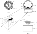
- the wheel assembly may be comprised of a partial inner ring 52 having a smaller diameter than the inner diameter of the outer ring 23, 26 as described in figure 5B and 5C .
- the partial inner ring 52 may just be a fraction of a ring.
- the transducer 20 may be attached to the inside of the partial inner ring 52 or may be fully or partially embedded in the partial inner ring 52.
- the smaller outer diameter of the partial inner ring 52 controls the area 54 of contact between the partial inner ring and the inside of the outer ring 23, 26.
- transducer(s) 20 and the coupling medium/ partial inner ring 52 than the fraction of an inner ring, for example a cylinder, spherical or coned form presenting a defined contact/coupling area between the coupling medium/ partial inner ring 52and the inside 26 of the outer ring 23.
- the shape of the orbital outer ring 23 may be provided in a form ideal for transmitting the acoustic signals from the transducers 20 to the material under test 15, including but not limited to round, rectangle, coned, or pyramid shaped as illustrated in fig. 5D .
- the material, design and contact areas in the interfaces between the transducers 20 and the partial inner ring 52, between the partial inner ring 52 and the inside of the outer ring 23, 26, and between the outer ring 23 and the material under test 15 defines the acoustic fields in the material under test 15 emitted from the transducers .
- the coupling medium/ partial inner ring 52 and the outer ring 23, 26 may be suspended in a similar way as discussed above, wherein the suspension feature 51 is coupled to the outer ring 23, 26, and the wheel assembly holds the transducer 20 and the coupling medium/the partial inner ring 52 at a constant radial position directed towards the material under test 15 whilst the outer ring 23, 26 rotates as the wheel assembly is moved along the surface of the material under test 15.
- Each wheel assembly of an instrument rig may be individually suspended, such that contact to the surface is maximized irrespective of unevenness in the surface of the material under test 15.
- the two contact areas being comprised of the interface between the inside 26 of the outer ring and the outside of the coupling medium/outside of the partial inner ring 52, and the outside of the outer ring 23 and the test material 15, may present different acoustic properties varying with the area of the contact interfaces, the material of the outer ring 23 and the coupling medium/the partial inner ring 52. Smaller contact areas give larger spread of the emitted signal from the transducer 20. The requirement to acoustic spread may be governed by the state of the surface of the material under test 15. A smooth surface of the test material 15, may allow for wider contact area of the contact interfaces.
- Figure 5D illustrates a coned form of the interface between the outer ring 23 and the material under test 15.
- the inside 26 of the outer ring and/or the outside of the coupling medium/outside of the partial inner ring 52 may comprise a lubricating formula, or be of a low friction dry material having required acoustic properties.
- a low friction dry material having required acoustic properties.
- Such material may for example be ROBALON ® , or any type of polymer or polytetrafluoroethylene (PTFE), graphite, hexagonal boron nitride, molybdenum disulfide, tungsten disulfide, metal alloys, PVDF or strongly hydrated brush polymers, or others.
- PTFE polytetrafluoroethylene
- the acoustic properties of the wheel assembly should be adapted to the composition of the test material 15.
- the coupling medium/the partial inner ring 52 and the outer ring 23, 26 enables adequate signal transmission through the wheel assembly into the material under test 15 without requiring any coupling fluid, and hence no need for advanced sealing features to hold the coupling fluid.
- test instruments can therefore be made much lighter and compact, with a simpler design that is easier to mount and dismount, and parts and materials of the wheel assembly and transducers may be altered to fit the material to be inspected 15 more readily.
- FIG. 6A, and 6B and 6C A further example of a wheel assembly is shown in figure 6A, and 6B and 6C .
- the transducers 20' are mounted radially partially or completely embedded in a single orbital ring 61, wherein the transducer outer surface represents the orbital outer ring as discussed in the above embodiments.
- the latter embodiment facilitates for a simpler implementation of production and adding the signal and electrical cabling 63 and contact pads 62, and a slip ring contact 65.
- the wheel may further be implemented without an axle and attached to a bearing wheel 64 via for example a ball bearing unit 66.
- the bearing wheel 64 may further have connecting means 67, such as bolt conduits for fastening to a chassis or a second wheel assembly.
- the wheel assembly may have recesses 68 for each transducer 20', which completely “buries” the transducer 20' into the single orbital ring 61,
- the transducer comprising an outer "capsule” 69 having an endurable material with a known acoustic impedance and such present an even outer surface and constitute the orbital outer ring 23'.
- the transducers may have a physical form such that when mounted around the wheel assembly they will touch the neighbour transducer on both sides, and thus represent a continuous track.
- a wide variety of survey tasks ranging from detecting corrosion areas on steel plates, pipes and structures, detecting cracks, flaws and detecting voids and delamination in composite materials, for example Carbone sheets or frames, or even woven fiberglass and glass reinforced plastic as used in light weight boat and airplane constructions.
- detecting corrosion areas on steel plates, pipes and structures detecting cracks, flaws and detecting voids and delamination in composite materials, for example Carbone sheets or frames, or even woven fiberglass and glass reinforced plastic as used in light weight boat and airplane constructions.
- the present invention provides a solution to this in that the design of the wheel assemblies can be very flexibly arranged in modules of single wheel assembly to a multiple wheel assemblies arranged in an array mounted on an axle or on individual adapted frame connection arrangements.
- wheel assemblies of the type discussed in figure 6 is individually arranged on corresponding ball bearing connectors 72 to a frame 71, the wheels being arranged as three modules 73, 74, 75 having different wheel characteristics, and thus enabling a survey that can span several depth ranges simultaneously.
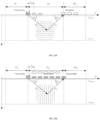
- present invention would be arranged with a number of wheel assemblies arranged perpendicularly on each side of the welding seam 140 as described in figure 14 , and rolled in a direction 141 along the path of the welding seam 140.
- wheel assemblies arranged perpendicularly on each side of the welding seam 140 as described in figure 14 , and rolled in a direction 141 along the path of the welding seam 140.
- number of wheels and individual characteristic of the wheel assemblies it is possible to cover a wide depth range analysis.
- the transducer design will also contribute to the total characteristic of the wheel assemblies.
- wave guiding characteristics such as shear waves and
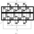
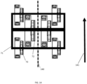
- Figure 8 illustrates how two arrays of wheel assemblies constituting two wheel modules arranged on two axles 22, 22' coupled to a frame element 71.
- One or more wheel assemblies 1, 1' of the invention described above may be mounted in a frame 70 as shown in figure 7 - 8 .
- Figure 8 show how two wheel modules 1, 1', 100 are mounted in brackets/ frame 71.
- the signaling cables 74 are lead through the frame 70.
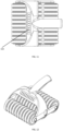
- FIG 9-12 Another embodiment of the invention is illustrated in figure 9-12 showing three wheel modules 1, 1', 100 of the innovation mounted in a handheld frame 120, where a handle 121 is mounted to the frame 120.
- the handheld device of the invention may be operated to store received signals together with positional information calculated out from a predefined starting pint by registering the movement over the test material by the rolling motion of the wheels of the invention or other mechanisms such as for example a computer mouse device (not show) or infrared measuring means or the like (not shown).
- the handheld device may have on board or attachable, via cable, induction or wireless communication access to: energy source, memory, control logic, input and output control ports, display and audio.
- Indication lights 150 may be arranged on the frame for purposes such as indicating contact status between the device and the test material, alarm status if preset signal pattern is received, or if received signal in a specific position is not valid.
- Indication lights may be color-coded, such as for example red light if no contact or green light when contact is detected between the device and test material. Other colors and switching pattern may be use for different purposes. One such purpose may be as a self-test indicator to be run prior to each job. It is also possible to use lights in a calibration routine where for example the device may be rolled over a known test material with a known surface with a known expected test result when transducers emit signals in line with a preset test pattern and frequencies. If expected received signal is verified the device is cleared for operation. Verified device may be identified by a preset light pattern displayed by the indication lights 150.
- a connected computer may also be used for purposes of storing, calibration, test and evaluation of test results.
- Computer may be connected by cable, wireless communication or by transfer of data via a storage memory device.
- a storage memory device may be detachably mounted to the electronic circuits in the device, or may be connectable via an interface at the time of transfer operation.
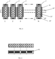
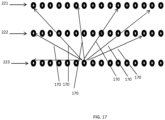
- the array of transducers may be used in different modes. Two different modes are shown in figure 13A and 13B . Other modes can be utilized.
- FIG 13A it is shown a mode for along-track inspection.
- One array of transducers e.g. the trailing wheel modules 1, 1', 100 of the invention, are used for emitting signals into the underground of the test material, and one array of transducers, e.g. the leading wheel modules 1, 1', 100 of the invention is used as receiving means for receiving the emitted signals that has traveled into and through the test material and reflected from this.
- FIG 13B it is shown a mode for cross-track inspection. This is achieved by allocating a number of transducers in one array of transducers for emitting the ultrasonic signal, and a number of transducers of the same array of transducers to receive the signal when reflected from the test material.
- One transducer may both emit and receive.
- a transducer in the peripheral section of the array of transducers is emitting signals into the underground of the test material and one or more transducers in the mid-section of the array of transducers receives the reflected signals.
- a transducer in the trailing array of transducers may emit, whilst the two leading arrays of transducers receive, or even all arrays of transducers may be set up to be receiving arrays of transducers were one or more arrays of transducers also emit.
- One likely configuration in a system comprising 3 arrays of transducers/ wheel modules 1, 1', 100 such as in the handheld example above is to use the transducers in the middle array of transducers for emission of ultrasonic signals, and the two outer arrays of transducers/ wheel modules 1, 1', 100 for receiving the reflected signal from the test material.
- Transducers may be used for emission or reception only, and both emission and reception, of ultrasonic signals and reflections.
- a transducer serving as both emitting and receiving transducer for the same ultrasonic signal i.e. the transducer emit an ultrasonic signal and then wait for the reflections of the signal and then receive the reflected signal, will only receive and detect reflections from objects or the like or material in the path of the emitted signal. If the object is a small vertical crack below the transducer, the reflected signal may be very weak and difficult to detect.
- each transducer either emit or receive an ultrasonic signal, not only measure reflected signals, but also measure the signal transmitted through the test material, and thus be able to measure the lack of reflection, or for example the time-of-flight diffraction.
- These types of measurements will provide for better S/N ratio in the measurement data.
- Such configuration will be able to detect the omission of a reflected signal.
- the receiving transducer will detect that the signal is not received as expected, and a conclusion may then indicate that there is a blocking medium between the emitting and receiving transducer, such as a crack, hole, non-relaying medium or other.
- the above additional ability to detect omission of a reflection may be utilized by a single wheel transducer setup of the invention as explained for figure 13B above. Enhancing the analyzing effect further may be achieved with the present invention by combining the feature explained in Figure 13B with the features of using more than one wheel module 1, 1', 100 as, one example of which is explained for the transducer setup in Figure 13A above.
- the different transducer setups may be optimized further to detect along track oriented cracks, air pockets, obstructions, with the cross track inspection feature as explained for figure 13B above, or across track oriented cracks, air pockets, obstructions, with the along track inspection feature as explained for figure 13A .
- the invention may be used to find welding flaws, and delamination/air pockets in sandwich structures, such as used in ships or wings (planes, wind turbines).
- sandwich structures may be constructed of multiple layers of different materials. All with potentially different response features relative ultrasonic signals of specific frequencies.
- the present invention may be controlled in a manner to optimize the response at the specific depth of the test material where a specific sandwich layer interface is located.
- Another example of embodiment is to use the invention to detect detachments/air pockets under building tiles, such as in a bathroom floor, where the outer layer is ceramic, and the inner layer is of concrete or wood, possibly with a water tight membrane structure in between.
- One possible regime of pattern is to let all transducers in turn be the emitting transducer, and let all transducers act as receivers for all the reflections of an emitted signal. This way it is possible to map all test material from all angles, sideways, forwards, backwards, angled in all directions and directly below. Using the motion of the device of the invention as another parameter it is possible to make several such measurements when moving over the test material. For example an air pocket in the concrete would then be thoroughly exploited from many directions several times, and no "hidden" weaknesses will be omitted.
- a different regime is to allocate one or more wheel modules as transmitting transducers, and other wheel modules as receiving transducers, and then activate several transmitting transducers simultaneously, and receive all reflected signals with the remaining transducers operating in receiving mode.
- the transducers may be selected for being used with multiple and variable frequencies.
- execution regimes may include, but is not limited to, different beam-forming techniques.
- One example of an execution regime may be SAFT (Synthetic Aperture Focusing Technique).
- Analysis of the data received from the test material may provide for the compilation of detailed 2D and/or 3D images of the test material at various depths below the surface of the test material, typically 0 - 15 cm below the surface of the test material.
- Figure 15 show a system where three pairs of wheel modules 1, 1', 100 of the invention is combined to provide a system for inspection of large volumes of test material.
- Each pair of wheel modules 1, 1', 100 is mounted to an individual bracket 70, and the three brackets are mounted to a carriage 200.
- the carriage further comprises a computing/controlling means 204, a laser measuring device 202, and a display unit 201.
- Each pair of wheels are individually adapting to the surface, as each section 12 of each wheel is individually adapting to the surface.
- the device in Figure 15 may have on board or attachable, via cable, induction or wireless communication access to: energy source, data storage, control logic, input and output control ports, display and audio.
- Indication lights as described for the handheld device above may be comprised in this system as well as in all versions of embodiments of the invention, and for the same purposes as discussed above.
- the carriage may comprise means for driving the carriage, e.g. an electromotor (not shown), remote controller features, and further comprise energy source or sources, handles 205 for manually pushing and/or steering the carriage and means for wireless communication with an external control unit (not shown).
- the control unit may be preprogrammed to guide the carriage to cover all segments of the test material as illustrated in figure 16 .
- a real life representation show the carriage position 200, the direction of movement 211, and the areas that have 212, 213, 214/ have not yet 215 been inspected. It may even be possible to distinguish between previous track of inspection 212, current track of inspection 213, and the overlap 214 of current track 213 of inspection relative to the previous 212 track of inspection.
- the laser unit may be used for measurement of distance in order to define the carriage position on the test material.
- Another embodiment example is to use a device of the present invention to sample a painted steel construction.
- the present invention is able to collect samples of reflected ultrasonic signals that enable the data analysis to uncover cracks and defects in an unparalleled manner without the need to remove paint or other protection layer fixed to the surface of the steel construction.
- Using the ability to compose an instrument having wheel modules 1, 1', 100 with different characteristics may detect flaws and irregularities on a much wider depth range on any material, or combination of material, wherein the different wheel modules 1, 1', 100 may be optimized for use on a specific lever of the test material, whether if that is a thickness measurement of a pipe, deterioration of a hull or tank, a bridge road armoring, a plane wing, radio mast bracket welding or other.
Landscapes
- Physics & Mathematics (AREA)
- Health & Medical Sciences (AREA)
- Life Sciences & Earth Sciences (AREA)
- Chemical & Material Sciences (AREA)
- Analytical Chemistry (AREA)
- Biochemistry (AREA)
- General Health & Medical Sciences (AREA)
- General Physics & Mathematics (AREA)
- Immunology (AREA)
- Pathology (AREA)
- Acoustics & Sound (AREA)
- Investigating Or Analyzing Materials By The Use Of Ultrasonic Waves (AREA)
Applications Claiming Priority (2)
| Application Number | Priority Date | Filing Date | Title |
|---|---|---|---|
| NO20160998 | 2016-06-13 | ||
| PCT/NO2017/050156 WO2017217862A1 (en) | 2016-06-13 | 2017-06-13 | Device, system and method for emission and reception of ultrasonic signals to and from a test material |
Publications (4)
| Publication Number | Publication Date |
|---|---|
| EP3494395A1 EP3494395A1 (en) | 2019-06-12 |
| EP3494395A4 EP3494395A4 (en) | 2020-06-17 |
| EP3494395C0 EP3494395C0 (en) | 2024-09-18 |
| EP3494395B1 true EP3494395B1 (en) | 2024-09-18 |
Family
ID=60664176
Family Applications (1)
| Application Number | Title | Priority Date | Filing Date |
|---|---|---|---|
| EP17813662.8A Active EP3494395B1 (en) | 2016-06-13 | 2017-06-13 | Device, system and method for emission and reception of ultrasonic signals to and from a test material |
Country Status (7)
| Country | Link |
|---|---|
| US (2) | US11378553B2 (enExample) |
| EP (1) | EP3494395B1 (enExample) |
| JP (2) | JP7411329B2 (enExample) |
| CN (1) | CN109564196B (enExample) |
| BR (1) | BR112018075848B1 (enExample) |
| CA (1) | CA3046176A1 (enExample) |
| WO (1) | WO2017217862A1 (enExample) |
Families Citing this family (11)
| Publication number | Priority date | Publication date | Assignee | Title |
|---|---|---|---|---|
| US12358141B2 (en) | 2016-12-23 | 2025-07-15 | Gecko Robotics, Inc. | Systems, methods, and apparatus for providing interactive inspection map for inspection robot |
| JP7547128B2 (ja) * | 2020-09-11 | 2024-09-09 | キヤノンメディカルシステムズ株式会社 | 検査装置、検査システム、超音波診断装置、音響結合材装置、及びプログラム |
| CN112305075B (zh) * | 2020-10-28 | 2023-02-03 | 济南大学 | 压电超声传感器的布设方法及在水泥混凝土水化进程全方位在线监测中的应用 |
| CN113008982B (zh) * | 2021-02-08 | 2024-04-26 | 中科传启(苏州)科技有限公司 | 一种地面材质识别方法、装置及智能清洁装置 |
| CN113009819B (zh) * | 2021-02-09 | 2022-04-05 | 南京航空航天大学 | 一种基于力控制的椭圆振动切削加工方法 |
| US11865698B2 (en) | 2021-04-20 | 2024-01-09 | Gecko Robotics, Inc. | Inspection robot with removeable interface plates and method for configuring payload interfaces |
| US11971389B2 (en) | 2021-04-22 | 2024-04-30 | Gecko Robotics, Inc. | Systems, methods, and apparatus for ultra-sonic inspection of a surface |
| JP7693577B2 (ja) * | 2021-09-16 | 2025-06-17 | 株式会社東芝 | 音波検査装置、音波検査方法、及び接触部材 |
| WO2023085093A1 (ja) * | 2021-11-12 | 2023-05-19 | Jfeスチール株式会社 | 案内装置、案内方法、計測装置、物体の製造設備、計測方法、物体の製造方法、及び物体の品質管理方法 |
| NO348147B1 (en) * | 2023-02-06 | 2024-09-02 | Elop Tech As | A device, system and method for acoustic impedance adaptation |
| WO2024259133A2 (en) * | 2023-06-13 | 2024-12-19 | Gecko Robotics, Inc. | Systems, methods, and apparatus for concrete quality inspection |
Citations (1)
| Publication number | Priority date | Publication date | Assignee | Title |
|---|---|---|---|---|
| EP0023125A1 (en) * | 1979-07-19 | 1981-01-28 | British Gas Corporation | Inspection device and vehicle for ultrasonically inspecting pipelines |
Family Cites Families (30)
| Publication number | Priority date | Publication date | Assignee | Title |
|---|---|---|---|---|
| GB1118141A (en) * | 1965-03-26 | 1968-06-26 | Nat Res Dev | Improvements in ultrasonic transmitting or receiving devices |
| US3732444A (en) | 1969-06-12 | 1973-05-08 | Rockwell International Corp | Tubular transducer and dry couplant therefor |
| GB1294404A (en) * | 1970-03-03 | 1972-10-25 | Secr Defence | Improvements in ultrasonic inspection devices |
| US3612920A (en) * | 1970-10-05 | 1971-10-12 | Branson Instr | Wheel-type transducer probe |
| EP0001674B1 (en) * | 1977-08-23 | 1981-08-12 | British Gas Corporation | Wheel probe for ultrasonic inspection of pipelines |
| FR2580813B1 (fr) * | 1985-04-17 | 1987-07-03 | Aerospatiale | Dispositif de controle par ultra-sons pourvu d'un organe de roulement |
| US4986119A (en) * | 1988-05-06 | 1991-01-22 | Gicewicz Gerald P | Vehicle diagnostic device |
| JPH03269360A (ja) | 1990-03-20 | 1991-11-29 | Tokimec Inc | 回転型探触子 |
| US5404755A (en) | 1992-04-10 | 1995-04-11 | Olson Engineering, Inc. | Scanning apparatus and method for non-destructive materials evaluation and mapping through use of acoustic waves |
| US6055862A (en) * | 1996-06-10 | 2000-05-02 | Herzog Services, Inc. | Method of and an apparatus for detecting, identifying and recording the location of defects in a railway rail |
| JPH1151917A (ja) | 1997-08-07 | 1999-02-26 | Nkk Corp | タイヤ型アレイ探触子および測定装置 |
| US6317387B1 (en) * | 1997-11-20 | 2001-11-13 | D'amaddio Eugene R. | Method and apparatus for inspecting a submerged structure |
| GB9820119D0 (en) * | 1998-09-15 | 1998-11-11 | Univ Cranfield | Ultrasound couplant |
| CN1103449C (zh) * | 1998-10-23 | 2003-03-19 | 李钢 | 钢轨超声探轮和探伤装置 |
| US6536553B1 (en) | 2000-04-25 | 2003-03-25 | The United States Of America As Represented By The Secretary Of The Army | Method and apparatus using acoustic sensor for sub-surface object detection and visualization |
| US6688178B1 (en) * | 2001-03-02 | 2004-02-10 | Materials Systems, Inc. | Roller transducer apparatus |
| US7305885B2 (en) * | 2004-09-30 | 2007-12-11 | General Electric Company | Method and apparatus for phased array based ultrasonic evaluation of rail |
| US7758524B2 (en) * | 2004-10-06 | 2010-07-20 | Guided Therapy Systems, L.L.C. | Method and system for ultra-high frequency ultrasound treatment |
| DE102004061870B3 (de) * | 2004-12-22 | 2006-06-14 | Siemens Ag | Sensorrad zur akustischen Untersuchung eines Messobjektes und Verwendung des Sensorrades |
| US7908923B2 (en) * | 2006-12-07 | 2011-03-22 | Siemens Aktiengesellschaft | Method of non-destructively testing a work piece and non-destructive testing arrangement |
| US20100324418A1 (en) * | 2009-06-23 | 2010-12-23 | Essa El-Aklouk | Ultrasound transducer |
| US8264126B2 (en) * | 2009-09-01 | 2012-09-11 | Measurement Specialties, Inc. | Multilayer acoustic impedance converter for ultrasonic transducers |
| JP2012068230A (ja) | 2010-08-25 | 2012-04-05 | Nippon Soken Inc | 触媒のクラック発生検知装置 |
| US9027406B2 (en) * | 2011-05-16 | 2015-05-12 | General Electric Company | Transducer apparatus and method for assembling a transducer apparatus |
| US8418563B2 (en) * | 2011-08-22 | 2013-04-16 | Herzog Services, Inc. | Apparatus for detecting defects |
| EP2610432B8 (en) * | 2011-12-26 | 2016-08-03 | Services Pétroliers Schlumberger | Downhole ultrasonic transducer and method of making same |
| GB201214273D0 (en) * | 2012-08-09 | 2012-09-26 | Airbus Uk Ltd | .Improvements to radius inspection tools |
| EP2738553B1 (en) * | 2012-12-03 | 2020-10-28 | Airbus Operations S.L. | Ultrasound inspection system and ultrasonic quality control method |
| NO337942B1 (no) * | 2014-09-19 | 2016-07-18 | Elop As | Ultralydanordning |
| CN105548352B (zh) * | 2015-11-17 | 2018-02-06 | 苏州博昇科技有限公司 | 一种无端部检测盲区的电磁超声波换能器 |
-
2017
- 2017-06-13 CN CN201780047399.0A patent/CN109564196B/zh active Active
- 2017-06-13 CA CA3046176A patent/CA3046176A1/en active Pending
- 2017-06-13 WO PCT/NO2017/050156 patent/WO2017217862A1/en not_active Ceased
- 2017-06-13 JP JP2018565028A patent/JP7411329B2/ja active Active
- 2017-06-13 EP EP17813662.8A patent/EP3494395B1/en active Active
- 2017-06-13 US US16/309,392 patent/US11378553B2/en active Active
- 2017-06-13 BR BR112018075848-5A patent/BR112018075848B1/pt active IP Right Grant
-
2022
- 2022-06-14 US US17/806,757 patent/US11815495B2/en active Active
- 2022-11-02 JP JP2022176406A patent/JP2023017901A/ja active Pending
Patent Citations (1)
| Publication number | Priority date | Publication date | Assignee | Title |
|---|---|---|---|---|
| EP0023125A1 (en) * | 1979-07-19 | 1981-01-28 | British Gas Corporation | Inspection device and vehicle for ultrasonically inspecting pipelines |
Also Published As
| Publication number | Publication date |
|---|---|
| US20190162703A1 (en) | 2019-05-30 |
| WO2017217862A1 (en) | 2017-12-21 |
| CA3046176A1 (en) | 2017-12-21 |
| EP3494395A1 (en) | 2019-06-12 |
| EP3494395C0 (en) | 2024-09-18 |
| BR112018075848B1 (pt) | 2023-01-10 |
| JP2019518216A (ja) | 2019-06-27 |
| US11378553B2 (en) | 2022-07-05 |
| BR112018075848A2 (pt) | 2019-03-19 |
| CN109564196A (zh) | 2019-04-02 |
| JP7411329B2 (ja) | 2024-01-11 |
| US20220341893A1 (en) | 2022-10-27 |
| EP3494395A4 (en) | 2020-06-17 |
| JP2023017901A (ja) | 2023-02-07 |
| CN109564196B (zh) | 2022-11-29 |
| US11815495B2 (en) | 2023-11-14 |
Similar Documents
| Publication | Publication Date | Title |
|---|---|---|
| US11815495B2 (en) | Device, system and method for emission and reception of ultrasonic signals to and from a test material | |
| JP6549716B2 (ja) | 超音波信号変換器のための装置、方法およびシステム | |
| US10557831B2 (en) | Pipeline crack detection | |
| CN103776499B (zh) | 海底冷泉天然气渗漏流量原位超声波测量系统 | |
| US11420692B2 (en) | Surface wave detection of surface defects | |
| US20250060065A1 (en) | Inspection robot | |
| US11085899B2 (en) | Methods and apparatus for acoustic assessment from the interior of fluid conduits | |
| US20210255150A1 (en) | Device for examining the interior of a pipe using multi-element ultrasound | |
| EP2984479B1 (en) | Ultrasonic inspection using incidence angles | |
| WO2024167415A1 (en) | A device, system and method for acoustic impedance adaptation | |
| Dobie et al. | P0-8 Robotic Based Reconfigurable Lamb Wave Scanner for Non-Destructive Evaluation |
Legal Events
| Date | Code | Title | Description |
|---|---|---|---|
| STAA | Information on the status of an ep patent application or granted ep patent |
Free format text: STATUS: THE INTERNATIONAL PUBLICATION HAS BEEN MADE |
|
| PUAI | Public reference made under article 153(3) epc to a published international application that has entered the european phase |
Free format text: ORIGINAL CODE: 0009012 |
|
| STAA | Information on the status of an ep patent application or granted ep patent |
Free format text: STATUS: REQUEST FOR EXAMINATION WAS MADE |
|
| 17P | Request for examination filed |
Effective date: 20190111 |
|
| AK | Designated contracting states |
Kind code of ref document: A1 Designated state(s): AL AT BE BG CH CY CZ DE DK EE ES FI FR GB GR HR HU IE IS IT LI LT LU LV MC MK MT NL NO PL PT RO RS SE SI SK SM TR |
|
| AX | Request for extension of the european patent |
Extension state: BA ME |
|
| DAV | Request for validation of the european patent (deleted) | ||
| DAX | Request for extension of the european patent (deleted) | ||
| RIC1 | Information provided on ipc code assigned before grant |
Ipc: G01N 29/22 20060101ALI20200507BHEP Ipc: G01N 29/26 20060101ALI20200507BHEP Ipc: G01N 29/24 20060101AFI20200507BHEP Ipc: G01N 29/04 20060101ALI20200507BHEP Ipc: G01N 29/28 20060101ALI20200507BHEP |
|
| A4 | Supplementary search report drawn up and despatched |
Effective date: 20200515 |
|
| RAP1 | Party data changed (applicant data changed or rights of an application transferred) |
Owner name: ELOP TECHNOLOGY AS |
|
| STAA | Information on the status of an ep patent application or granted ep patent |
Free format text: STATUS: EXAMINATION IS IN PROGRESS |
|
| 17Q | First examination report despatched |
Effective date: 20220512 |
|
| GRAP | Despatch of communication of intention to grant a patent |
Free format text: ORIGINAL CODE: EPIDOSNIGR1 |
|
| STAA | Information on the status of an ep patent application or granted ep patent |
Free format text: STATUS: GRANT OF PATENT IS INTENDED |
|
| RIC1 | Information provided on ipc code assigned before grant |
Ipc: G01N 29/28 20060101ALI20240411BHEP Ipc: G01N 29/04 20060101ALI20240411BHEP Ipc: G01N 29/22 20060101ALI20240411BHEP Ipc: G01N 29/265 20060101ALI20240411BHEP Ipc: G01N 29/24 20060101AFI20240411BHEP |
|
| INTG | Intention to grant announced |
Effective date: 20240513 |
|
| GRAS | Grant fee paid |
Free format text: ORIGINAL CODE: EPIDOSNIGR3 |
|
| GRAA | (expected) grant |
Free format text: ORIGINAL CODE: 0009210 |
|
| STAA | Information on the status of an ep patent application or granted ep patent |
Free format text: STATUS: THE PATENT HAS BEEN GRANTED |
|
| RIN1 | Information on inventor provided before grant (corrected) |
Inventor name: WAGLE, SANAT Inventor name: CHAPAGAIN, KAMAL RAJ Inventor name: MELANDSOE, FRANK Inventor name: BJERKE, WERNER Inventor name: MELANDSOE, TERJE |
|
| AK | Designated contracting states |
Kind code of ref document: B1 Designated state(s): AL AT BE BG CH CY CZ DE DK EE ES FI FR GB GR HR HU IE IS IT LI LT LU LV MC MK MT NL NO PL PT RO RS SE SI SK SM TR |
|
| REG | Reference to a national code |
Ref country code: GB Ref legal event code: FG4D |
|
| REG | Reference to a national code |
Ref country code: CH Ref legal event code: EP |
|
| REG | Reference to a national code |
Ref country code: DE Ref legal event code: R096 Ref document number: 602017084945 Country of ref document: DE |
|
| REG | Reference to a national code |
Ref country code: IE Ref legal event code: FG4D |
|
| U01 | Request for unitary effect filed |
Effective date: 20241014 |
|
| U07 | Unitary effect registered |
Designated state(s): AT BE BG DE DK EE FI FR IT LT LU LV MT NL PT RO SE SI Effective date: 20241030 |
|
| PG25 | Lapsed in a contracting state [announced via postgrant information from national office to epo] |
Ref country code: NO Free format text: LAPSE BECAUSE OF FAILURE TO SUBMIT A TRANSLATION OF THE DESCRIPTION OR TO PAY THE FEE WITHIN THE PRESCRIBED TIME-LIMIT Effective date: 20241218 |
|
| PG25 | Lapsed in a contracting state [announced via postgrant information from national office to epo] |
Ref country code: GR Free format text: LAPSE BECAUSE OF FAILURE TO SUBMIT A TRANSLATION OF THE DESCRIPTION OR TO PAY THE FEE WITHIN THE PRESCRIBED TIME-LIMIT Effective date: 20241219 |
|
| PG25 | Lapsed in a contracting state [announced via postgrant information from national office to epo] |
Ref country code: HR Free format text: LAPSE BECAUSE OF FAILURE TO SUBMIT A TRANSLATION OF THE DESCRIPTION OR TO PAY THE FEE WITHIN THE PRESCRIBED TIME-LIMIT Effective date: 20240918 |
|
| PG25 | Lapsed in a contracting state [announced via postgrant information from national office to epo] |
Ref country code: RS Free format text: LAPSE BECAUSE OF FAILURE TO SUBMIT A TRANSLATION OF THE DESCRIPTION OR TO PAY THE FEE WITHIN THE PRESCRIBED TIME-LIMIT Effective date: 20241218 |
|
| PG25 | Lapsed in a contracting state [announced via postgrant information from national office to epo] |
Ref country code: RS Free format text: LAPSE BECAUSE OF FAILURE TO SUBMIT A TRANSLATION OF THE DESCRIPTION OR TO PAY THE FEE WITHIN THE PRESCRIBED TIME-LIMIT Effective date: 20241218 Ref country code: NO Free format text: LAPSE BECAUSE OF FAILURE TO SUBMIT A TRANSLATION OF THE DESCRIPTION OR TO PAY THE FEE WITHIN THE PRESCRIBED TIME-LIMIT Effective date: 20241218 Ref country code: HR Free format text: LAPSE BECAUSE OF FAILURE TO SUBMIT A TRANSLATION OF THE DESCRIPTION OR TO PAY THE FEE WITHIN THE PRESCRIBED TIME-LIMIT Effective date: 20240918 Ref country code: GR Free format text: LAPSE BECAUSE OF FAILURE TO SUBMIT A TRANSLATION OF THE DESCRIPTION OR TO PAY THE FEE WITHIN THE PRESCRIBED TIME-LIMIT Effective date: 20241219 |
|
| PG25 | Lapsed in a contracting state [announced via postgrant information from national office to epo] |
Ref country code: IS Free format text: LAPSE BECAUSE OF FAILURE TO SUBMIT A TRANSLATION OF THE DESCRIPTION OR TO PAY THE FEE WITHIN THE PRESCRIBED TIME-LIMIT Effective date: 20250118 |
|
| PG25 | Lapsed in a contracting state [announced via postgrant information from national office to epo] |
Ref country code: SM Free format text: LAPSE BECAUSE OF FAILURE TO SUBMIT A TRANSLATION OF THE DESCRIPTION OR TO PAY THE FEE WITHIN THE PRESCRIBED TIME-LIMIT Effective date: 20240918 |
|
| PG25 | Lapsed in a contracting state [announced via postgrant information from national office to epo] |
Ref country code: ES Free format text: LAPSE BECAUSE OF FAILURE TO SUBMIT A TRANSLATION OF THE DESCRIPTION OR TO PAY THE FEE WITHIN THE PRESCRIBED TIME-LIMIT Effective date: 20240918 |
|
| PG25 | Lapsed in a contracting state [announced via postgrant information from national office to epo] |
Ref country code: CZ Free format text: LAPSE BECAUSE OF FAILURE TO SUBMIT A TRANSLATION OF THE DESCRIPTION OR TO PAY THE FEE WITHIN THE PRESCRIBED TIME-LIMIT Effective date: 20240918 Ref country code: PL Free format text: LAPSE BECAUSE OF FAILURE TO SUBMIT A TRANSLATION OF THE DESCRIPTION OR TO PAY THE FEE WITHIN THE PRESCRIBED TIME-LIMIT Effective date: 20240918 |
|
| PG25 | Lapsed in a contracting state [announced via postgrant information from national office to epo] |
Ref country code: SK Free format text: LAPSE BECAUSE OF FAILURE TO SUBMIT A TRANSLATION OF THE DESCRIPTION OR TO PAY THE FEE WITHIN THE PRESCRIBED TIME-LIMIT Effective date: 20240918 |
|
| U20 | Renewal fee for the european patent with unitary effect paid |
Year of fee payment: 9 Effective date: 20250425 |
|
| PLBE | No opposition filed within time limit |
Free format text: ORIGINAL CODE: 0009261 |
|
| STAA | Information on the status of an ep patent application or granted ep patent |
Free format text: STATUS: NO OPPOSITION FILED WITHIN TIME LIMIT |
|
| 26N | No opposition filed |
Effective date: 20250619 |
|
| PGFP | Annual fee paid to national office [announced via postgrant information from national office to epo] |
Ref country code: GB Payment date: 20250731 Year of fee payment: 9 |